

Page 1
TFC Group LLP, Tower House,
Vale Rise, Tonbridge, Kent TN9 1TB
http://www.tfc-group.co.uk
ET3
RF Thermostat
INSTRUCTION MANUAL
TABLE OF CONTENTS
A. Installation and mounting
1, Installation
2, Wiring
3, Mounting
B, Start/Reset
C, Normal Operation
D, Setting Temperature
E, Jumper Selection
F, Jumper location
G, Comms Address Setting
H, Specification
I, Terminal Connecting Block Label
1
A, Installation & Mounting:
Caution:
Turn off the ET3 and any electrical devices that are to be
connected after installation. The installation must be carried
out by a qualified electrician and conform to current IEE
regulations.
1, Installation Location:
The thermostat (Transmitter) should be mounted on an inner wall 1.5m
above the floor in a position where it is readily affected by changes in the
ambient room temperature. Prevent direct exposure sunlight and moisture.
Do not place this unit where air circulation is low, or where it is susceptible
to rapid temperature changes (e.g. near a door or window). Do not position
near heating/cooling appliances.
3
Page
3
3
4
4
6
6
7
7
8/9
10
11
12
ET3 RF Thermostat
1, The system includes one wireless thermostat controller (Tx) plus one RF
receiver (Rx).
2, Transmits up to 20 meters indoors.
3, Communicates at 433.92MHz(USA/European Standard) and is designed
for unlicensed operation under FCC Part 15.
Warning:
1, There may be a dead zone in the RF communication. That means the
receiver may not be able to receive the message from the transmitter.
Before the installation, check the communication first. If the
communication fails, relocate the wireless thermostat.
2, If there is interference in communication, Follow the set-up procedure to
change the coding between the RF thermostat and receiver.
3, It is recommended that the RF thermostat and Receiver are mounted at
least 2 meters from electrical devices such as, radio, TV, PC etc. Do not
mount the RF thermostat or receiver on metal wall boxes as this will
interfere with the RF signal and reduce the range.
2
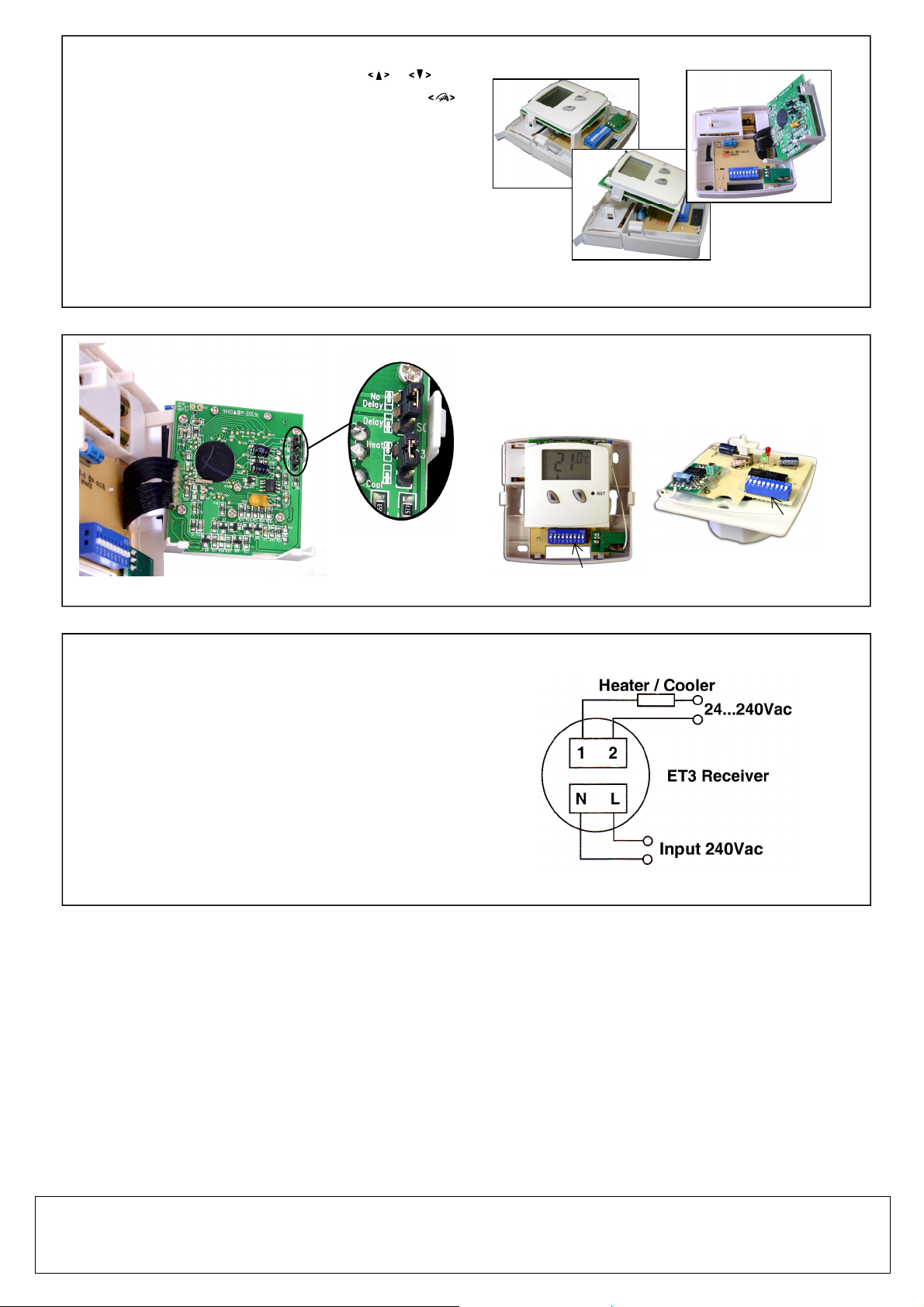
2, Wiring:
There are four terminals on the receiver. L , N , 1 & 2.
Volt free connection:
If connecting to a volt free system 220-240 VAC should be connected to
L & N and the switched pair into terminals 1 & 2. If the circuit has a send
and return, the send should be connected to terminal 2 and the return to
terminal 1.
Mains switching:
Connect 220-240 VAC to L & N, Link Live (L) to terminal 2. Terminal 1
gives a 230V AC switched live output when heating is in demand.
• Refer to the circuit diagram printed on rating label on the back of the
product.
• Push all wiring into wall prior to mounting to avoid trapping wires.
The thermostat should be protected by a fuse with a current rating no
larger than 10A.
3, Mounting:
Mount the ET3 Thermostat using the screw accessories provided through
slots/holes on rear face of the unit. Mount the receiver into back-box
provided.
4
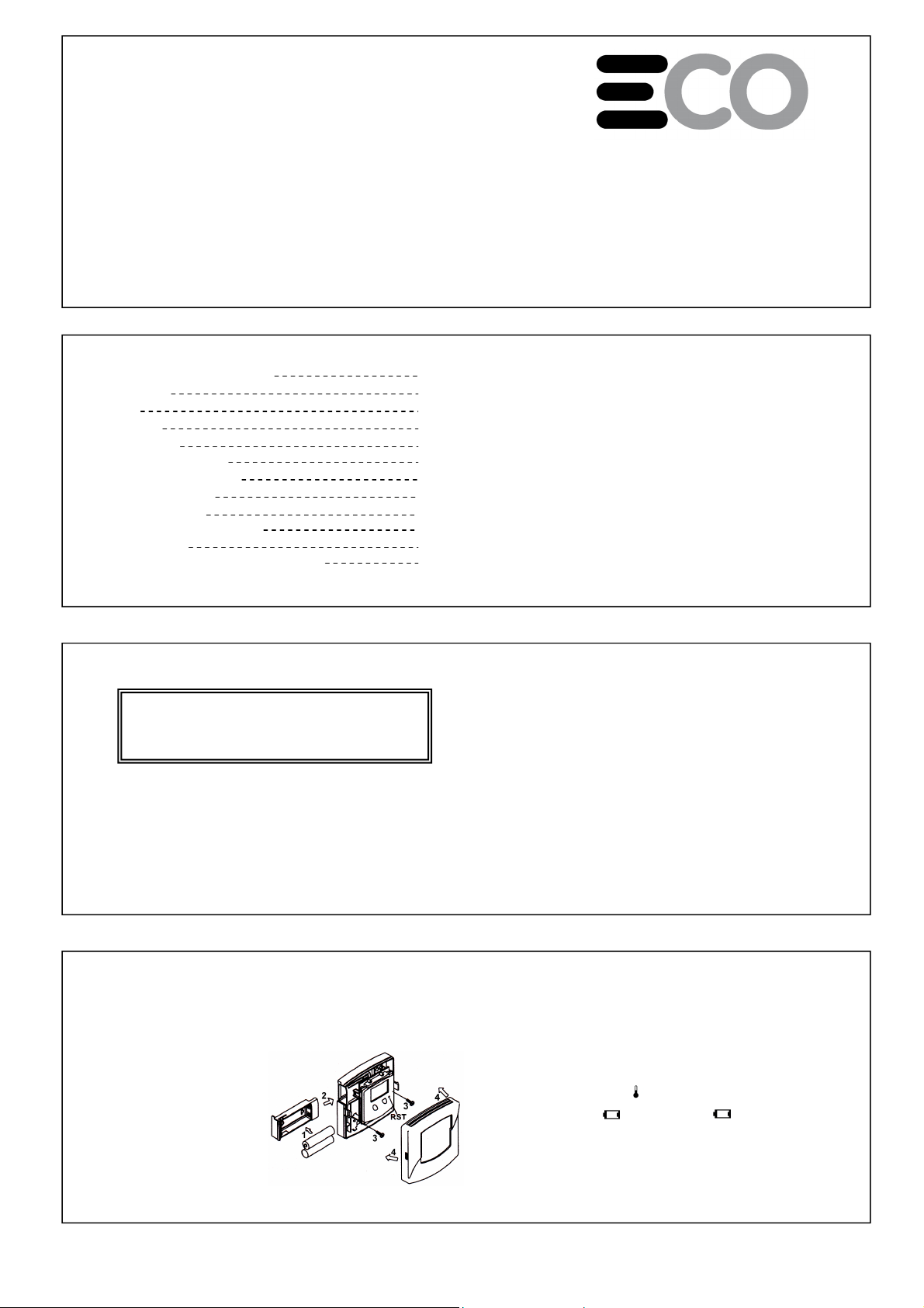
Transmitter Battery Installation / Replacement:
Caution: Turn off electrical devices and disconnect the supply to any
connected appliances before installing or replacing batteries. Replace only
with the same (AAA Alkaline) or equivalent batteries. Do not dispose of use d
batteries with household waste. Refer to your local area for correct disposal
method.
1, Pull out the battery draw.
2, Place new batteries taking note of
orientation of +/- on battery drawer.
3, Dispose old batteries properly.
4, Slide battery draw into position.
5, Check operation and press reset
(RST) if not functioning correctly.
(Figure 1)
5
B, Start/Reset:
1, After wiring and mounting, switch off all connected devices. Place 2 new
AAA 1.5V alkaline batteries ensuring correct orientation of battery
polarity. LCD display will show.
2, Press ‘RST’ to reset. The ET3 is now ready to control the heater/cooler.
3, Switch on the heater/cooler. The heater/cooler will remain off until the
ET3 activates the output
C, Normal Operation:
1, Temperature detection starts and LCD displays the room temperature.
The temperature indicator Will flash when heating is in demand and
will stop flashing once the set-point has been achieved.
2, If the battery is low, will be flashing. If has been flashing for 48
hours and the batteries have not been replaced, the ET3 will stop
measuring the room temperature and the LCD will go blank. The ET3 will
turn off the output and the heater/cooler will cease to operate. The
system will only function once the discharged batteries are removed and
new batteries are fitted.
6
Page 2
D, Setting Temperature:
- Adjust the temperature to your chosen set-point using the or
buttons.
- Ambient room temperature display will resume after 8 seconds and the
icon will disappear.
E, Jumper Selection:
Delay / No Delay Jumper:
Heater Cooler
No Delay 10sec 4mins
Delay 4mins 4mins
Choose the delay option if compressor heat is connected.
Heater/Cooler Jumper:
Select the heater option (default) when a heater is connected to the
receiver. Select the Cooler option when using the ET3 for a cooling
application, fan cooling etc. Press “reset” (RST) after modifying jumper
selections.
F, Jumper Locations:
1
3
2
7
Default jumper setting:
No Delay & Heating
9 10
H, Specification:
1, Temperature Measurement: 00C - 40C
(0.1
2, Accuracy: ± 0.50C
3, Temperature Control Range: 50C - 350C
(0.5
4, Terminals: 2.5mm2 Cable
5, Electronic Control: Type 2.B action
6, Transmitter Batteries: 2 x 1.5V AAA
Alkaline batteries
7, Receiver Input Voltage: 240V AC
8, Receiver Output Voltage: 24..240V AC
50/60Hz
10(3)A Max
9, Operating Temperature: 00C - 500C
10, Storage Temperature: 0
11, Sensing Element: NTC Thermistor
0
C/step)
0
C/step)
0
C - 600C
8
G, Comms Address Setting:
Inside the transmitter and receiver there is a bank of 9 dip switches for
setting a unique address (pairing). The receiver will ignore
communications from transmitters set to a different address. To access
the dip switches it is necessary to open the thermostat and remove the
front cover from the receiver by removing the two crosshead screws on
the rear cover.
Receiver
dip switches
Transmitter dip switches
I, Terminal Connecting Block Label:
The dip switches on both units must
be set identically to communicate.
11 12
TFC Group LLP, Tower House, Vale Rise, Tonbridge, Kent TN9 1TB
tel: 01732 351680 email: sales@tfc.uk.com web:tfc-group.co.uk
 Loading...