

Page 1

TFC Group LLP, Tower House,
Vale Rise, Tonbridge, Kent TN9 1TB
http://www.tfc-group.co.uk
ET2
Digital Programmable Thermostat
For
Weekday/Weekend Setting
INSTRUCTION MANUAL
TABLE OF CONTENTS
A. Installation and mounting
1, Installation
2, Wiring
3, Mounting
B, Start/Reset
C, Normal Time Mode
D, Normal Time Setting
E, Factory Defined Programs
F, Set Own Program
G, Temporary/Permanent Override Mode
H, Control Off/Sleep Mode
I, Jumper Selection
J, Specification
1
2, Wiring:
There are three terminals at the bottom of the ET2, labelled as
“Com” (Common), “NO” (normally open) and “NC” (normally closed).
Connect the appliance to the “NO” and “Com” terminals. Leaving the “NC”
terminal empty.
• Refer to the circuit diagram printed on rating label on the back of the
product.
• Push all wiring into wall prior to mounting to avoid trapping wires.
• The thermostat should be protected by the fused spur supplying the
heating system using a fuse with a current rating no larger than 5A.
3, Mounting:
Mount the ET2 using the screw accessories provided through slots/holes on
rear face of the unit.
Mains
Switching
3
Page
2
2
3
3
5
5
6
7
8
10
12
13
14
ET 2 LCD Programmable Thermostat
A, Installation & Mounting:
Caution:
Turn off the ET2 and any electrical devices that are to be
connected after installation. The installation must be carried
out by a qualified electrician and conform to current IEE
regulations.
1, Installation Location:
The thermostat should be mounted on an inner wall 1.5m above the floor in
a position where it is readily affected by changes in the ambient room
temperature. Prevent direct exposure sunlight and moisture. Do not place
this unit where air circulation is low, or where it is susceptible to rapid
temperature changes (e.g. near a door or window). Do not position near
heating/cooling appliances.
2
Battery installation / Replacement:
Caution: Turn off electrical devices and disconnect the supply to any
connected appliances before installing or replacing batteries. Replace only
with the same (AAA Alkaline) or equivalent batteries. Do not dispose of use d
batteries with household waste. Refer to your local area for correct disposal
method.
1, Pull out the battery draw.
2, Place new batteries taking note of
orientation of +/- on battery drawer.
3, Dispose old batteries properly.
4, Slide battery draw into position.
5, Check operation and press reset
if not functioning correctly.
(Figure 1)
4
B, Start/Reset:
1, After wiring and mounting, switch off all connected devices. Place 2
new AAA 1.5V alkaline batteries ensuring correct orientation of battery
polarity. LCD display will show.
2, Press ‘RST’ to reset. The ET2 is now ready to control the heater/cooler.
3, Switch on the heater/cooler. The heater/cooler will remain off until the
ET2 activates the output, with or displayed depending on
configuration for a heating or cooling application.
C, Normal Time Mode:
1, Temperature detection starts and LCD displays the room temperature.
2, If the battery is low, will be flashing. If has been flashing for 48
hours and the batteries have not been replaced, the ET2 will stop
measuring the room temperature and the LCD will go blank. The ET2 will
turn off the output and the heater/cooler will cease to operate. The
system will only function once the discharged batteries are removed and
new batteries are fitted.
5
3, In heating mode frost protection is activated automatically if the ambient
temperature falls below 50C. Will show in the display and the output
will be forced ON for heating or OFF if the ET2 is configured for cooling.
4, If the ambient temperature is below 00C “LO” will show in the display.
5, Above 400C “HI” will show in the display.
D. Setting the real-time clock:
1, Press , the day of week (1-7) will flash 1=Monday. Press ,
To select the current day of the week.
2, Press , the hour will flash, press , to set the hour.
3, Press , the minute will flash, press , to set the minute.
4, Pressing will return back to step 1 (day setting).
5, Press to confirm settings and return to the default screen.
Note: If no buttons are pressed within 10 seconds the ET2 will return to the
default screen
6
Page 2
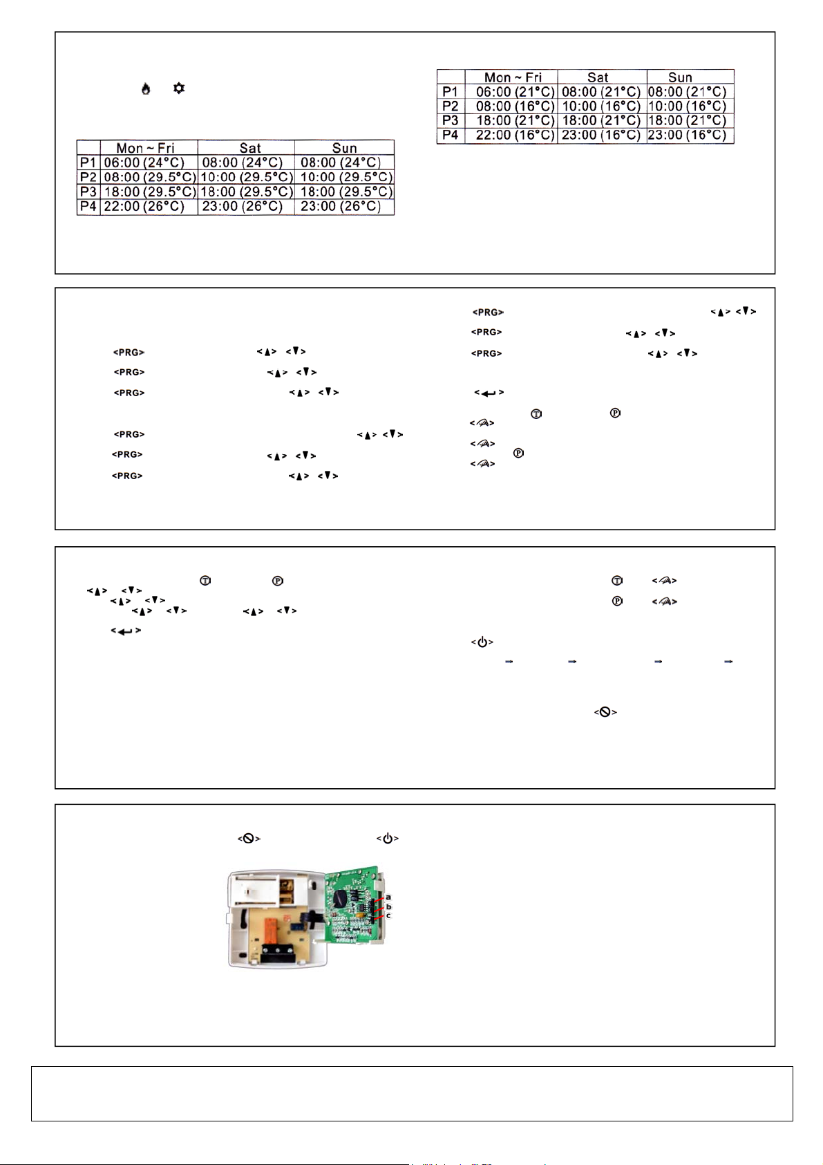
E, Factory Defined Programs:
The heater/cooler turns on according to the activated program and the
control temperature setting. When the heater/cooler is ON, the program
number and or will appear in the display.
The pre-defined programs are as below:
Cooler mode:
7
Heater mode:
F, Setting Your Own Program:
Mon to Fri, Sat and Sun are divided into four periods P1 to P4. The time set
for each period is the start time for that period. To set your own program
you should set the period start time and the temperature to be achieved
during that period.
e.g. In the table above P1 starts at 6am Monday and will hold the
temperature at 210C until period 2 (P2) starts at 8am, when the
temperature will be lowered to 160C until period 3 (P3) & the temperature
8
will raise to 210C until period 4 (P4). P4 will hold the temperature at 160C
until period 1 (P1) 6am. You can edit the preset times/temperature values
by following the steps below.
1, Press , the hour will flash, Press , to change the hour
setting.
2, Press , the minute will flash, Press , to change the
minute setting.
3, Press , the temperature will flash, Press , to change
the temperature set-point.
Repeat this sequence for P2, P3 & P4 (Mon-Fri)
4, Press , the hour will flash for P1 day 6 (Saturday), Press ,
to change the hour setting.
5, Press , the minute will flash, Press , to change the
minute setting.
6, Press , the temperature will flash, Press , to change
the temperature set-point.
Repeat this sequence for P2, P3 & P4 (Saturday)
Review and adjust the Override temperature:
1, With the ET2 in Temporary or Permanent override, press
or to display the Override temperature.
2, Press or for 2 seconds, the Override temperature will flash.
3, Release or and then use or to adjust the Override
temperature .
3, Press to exit Override temperature setting.
The ET2 will return to the default screen if no buttons are pressed after
10 seconds.
G, Temporary Override mode:
The Temporary Override mode is maintained until the start of the next
timed period.
Permanent Override mode:
The room temperature will be maintained at the Override temperature
set-point until the Override mode is released.
9
11
7, Press , the hour will flash for P1 day 7 (Sunday), Press ,
to change the hour setting.
8, Press , the minute will flash, Press , to change the
minute setting.
9, Press , the temperature will flash, Press , to change
the temperature set-point.
Repeat this sequence for P2, P3 & P4 (Sunday)
10, Press to confirm changes and return to default screen.
Selecting Temporary or Permanent Override Mode:
1, Press to change the mode from normal to Temporary Override.
The icon will be displayed.
2, Press again and the mode changes from Temporary to Permanent
Override mode. Icon will be displayed.
3, Press once more and the mode changes from Permanent Override
to normal timed operation.
10
Releasing Override mode:
1, When the ET2 is in Temporary Override Press twice to return to
normal timed operation.
2, When the ET2 is in Permanent Override Press once to return to
normal timed operation.
H, Control Off / Sleep Mode:
1, Press to select the sleep mode and control off mode. The sequence
is as below:
Normal mode Sleep mode Control Off mode Normal mode ….
2, Press any other button to exit the Control Off / Sleep mode and return to
normal operation.
Sleep Mode:
When the ET2 is in sleep mode the icon is displayed. The ET2 stops
measuring and controlling the temperature. The heater/cooler is turned
off, irrespective of the current setting temperature.
12
Control Off mode:
When the ET2 is in Sleep mode and icon is displayed, pressing
will put the ET2 into Control Off mode. The LCD display and the
heater / cooler are turned off, irrespective of the current control
temperature setting.
I, Jumper Selection:
Delay / No Delay Jumper
Heater Cooler
No Delay 10sec 4mins
Delay 4mins 4mins
Choose the Delay option if
compressor heat is connected.
12-hour / 24-hour mode jumper:
When the 12-hour option is selected, the time is shown in 12 hour mode.
Otherwise the time is displayed in-24 hour mode.
Heater / Cooler Jumper:
The ET2 can be set for a heating or cooling configuration via internal
a = 12/24 hours
b = Delay / No delay
c = Heater / Cooler
13
J. Specification:
1, Temperature measurement: 00C to 400C
(0.1
2, Accuracy: ± 0.50C
3, Temperature control range: 50C to 350C
(0.50C/step)
4, Switching: 24..250V AC 50/60Hz
5(3.5)A max
5, Terminals: 2.5mm2 cable
6, Electronic control: Type 2.B action
7, Battery: 2 x 1.5V AAA Alkaline battery
8, Operating temperature: 00C to 500C
9, Storage temperature: -100C to 600C
10, Sensing element: NTC thermister
0
C/step)
14
TFC Group LLP, Tower House, Vale Rise, Tonbridge, Kent TN9 1TB
tel: 01732 351680 email: sales@tfc.uk.com web:tfc-group.co.uk
 Loading...