

Texecom Odyssey X, Odyssey X-B, Odyssey X-E, Odyssey X Series, Odyssey X-W Installation Manual
...
Installation Manual
Odyssey X Series
INS627-2
Odyssey X Installation Manual
Introduction
Odyssey X is a new range of modular external warning d evices available in standard or backlit variants. The modular design allows for a choice of
front covers to be installed on the common backplate. Please see the specification table for full details of each model. Features include: -
• Modular design - Common backplate
• Backlit variants available
• High Intensity White Comfort LED's
• Single or twin piezo versions (Grade 2 or 3 respectively)
• Integral spirit level
• Clip on hinged lid with two "park" positions for easier
installation
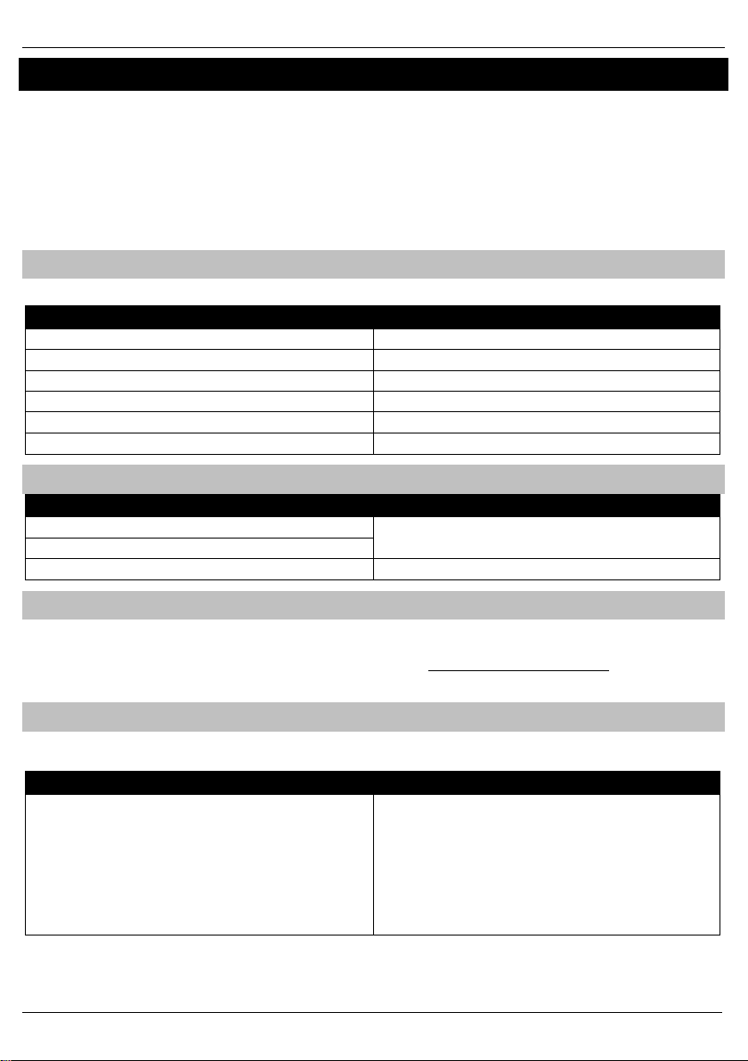
Backplate Variants
Several models are available, all are the same size and use the same covers.
Model Features
Odyssey X Grade 3 Sounder & Str obe Unit Twin Piezo
Odyssey X-B Grade 3 Sounder & Str obe Unit with Backlight Twin Piezo
Odyssey X-E Grade 2 Sounder & Strob e Unit Single Piezo
Odyssey X-BE Grade 2 Sounder & Str obe Unit with Backlight Single Pi ezo
Odyssey X-W (Premier Elite V2.11 or later) Grade 2 Wireless Sounder & Strobe Unit Single Piezo
Odyssey X-D Decoy backplate without electronics
Covers Options
Outer Colour & Infill Lens Colour
Black Frame+ White Insert
White Frame + White Inser t
Compatible covers X1 Cover or X3 Cover
• Combined inner lid and removal from mounting tamp er with
adjustable sensitivity
• Adjustable mount ing plates allowing "In situ" drilling
• Choice of Odyssey X1 or X3 front covers
• Backlight may be wired to panel outputs for increased
functionality
• Optional Graphic inserts for company branding
Blue, Red, Opaque White & Gr een
Graphic Inserts
Odyssey X sounders can accommodate a graphic insert, rather than traditional screen printed lids. Graphic inserts can be ordered directly from
Texecom.
Simply follow the instructions and submit your artwork at the following web address. http://www.texe.com/uk/branding.php
Once you have approved and paid for the artwork, inserts will be delivered directly to you.
Installation Workflow
Wired and Wireless O dyssey X have slightly different installation procedures, please make sure to adhere to the following workflow to ensure
trouble free installation and commissioning of your new sounder.
Wired Wireless
1. Select the desired location for the sounder
2. Install 8 core alarm cable from the sounder location back to
the control panel or expander.
3. Install the sounder
4. Commission system
2 INS627-2
1. Install control panel and/or wireless receiver
2. Learn all other wireless devices, and install them in their
desired location
3. Learn wireless sounder
4. Install wireless sounder in desired location
5. Commission system
6. Check signal security of a ll wireless devices
 Loading...