

Texecom Azura 360, Tempest, Odyssey 1, Odyssey 2, Odyssey 3 Installation Manual
...

2 INS154-4
Contents
Section Page
1. Installation 3
1.1 Mounting the Unit 3
1.2 Patented Engineer Hold-Off Mode 3
1.3 Installing the Unit 3
1.3.1 Optional “Battery First” Connection Method 4
1.4 Installing Multiple Units 5
1.4.1 SCB Mode 5
1.5 Commissioning 6
2. Servicing 6
3. Safety 7
4. Technical Specification 8
5. Warranty 10
6. Registered Installer Application Form 11

INS154-4 3
1. Installation
1.1 Mounting the Unit
Select a suitable position to mount the unit, which satisfies the following criteria:
• Highly prominent for maximum deterrence
• Additional shelter (e.g. under the eaves) is an advantage
• High enough to be out of normal reach to deter tampering
• Safe ladder access
• Good cable access
In addition to the corner screw fixing points, the unit also has a central keyhole to
simplify mounting and aid levelling.
Four screws and wall plugs are required for mounting the backplate to an even
surface. An additional screw may be required to provide wall tamper by fitting
through the screw hole next to the dual tamper microswitch. In doing so, care must
be taken to leave the screw head slightly proud to ensure that the microswitch
remains level and closes correctly when the outer cover is fitted.
For safety reasons the unit must be mounted securely on a suitable wall.
For maximum weatherproofing the unit should be flat to the wall.
For brick walls, BS 4737 specifies a minimum of three No. 10 steel screws
penetrating the brick (not the mortar or facing) by at least 40mm into suitable wall
plugs.
1.2 Patented Engineer Hold-Off Mode
For safety reasons, each Texecom sounder and strobe unit incorporates a unique
patented engineer Hold-Off mode. This mode prevents the unit from self-activating
during installation and maintenance, thereby allowing only bona fide engineers
access to the unit without any loss of tamper protection.
1.3 Installing the Unit
Connect the unit to the control panel as follows:
A (12V ) Permanent Positive Supply
B (BELL) Negative Applied Output to Activate Siren
C (TAMP) Negative Removed on Tamper Input
D (0V) Permanent Negative Supply
S (STRB) Negative Applied Output to Activate Strobe
Although the unit has been designed to be compatible with a wide range of control
panels, for optimum performance, it is highly recommended that the unit should be used
with Texecom's ran
g
e of control panels.
4 INS154-4
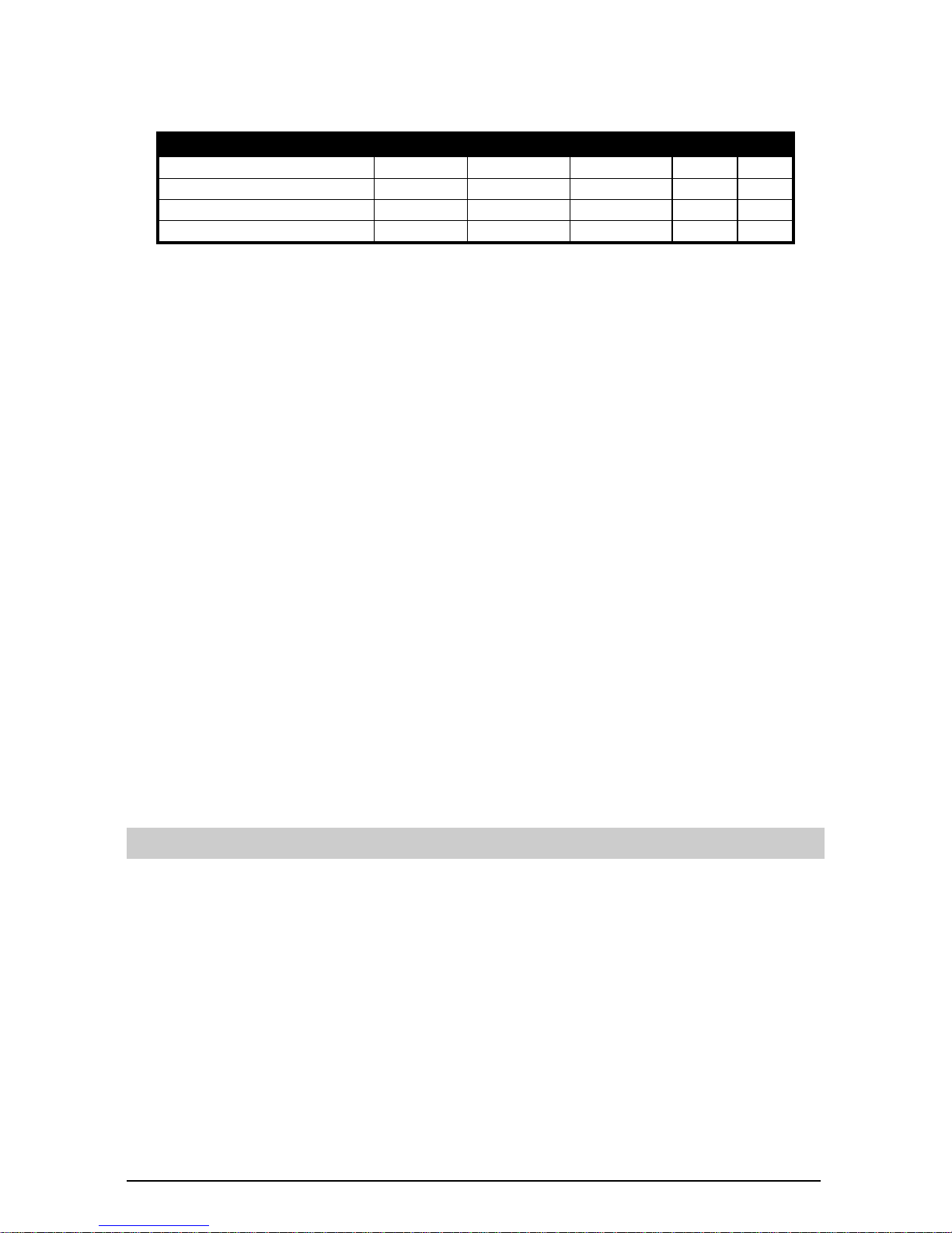
The following table illustrates how to connect the unit to the Texecom range and
other control panels:
A B C D S
Texecom Control Panel A B C D S
C&K Active 5, Securit BELL + S - 24 TAMPER AUX - ST Menvier TS510, 700, 800 BELL 12V BELL TRIG BELL TMP 0V STB
Scantronic 9448 to 9800 +12V BELL TR 0V STR
When connecting the unit to the control panel, it is recommended that wiring should
be connected to the unit first and the control panel second. The unit should then be
initially powered from the control panel. If the tamper circuit is open the siren will
sound for 5 seconds after which it will automatically enter Hold-Off mode and disable
Self-Activate (S/A) on tamper. This will prevent the unit from self-activating as long as
the tamper circuit remains open. An open tamper circuit is indicated by only the
left-hand side LED flashing. Connect the battery by moving the red battery wire from
the “N/C” (No Connect) terminal to the “Battery +” terminal. Fit the outer cover and
secure with the M6 screw(s) provided.
When the outer cover is replaced and the tamper circuit is closed, the LEDs will
alternate rapidly, confirming that the tamper circuit is secure and signalling that S/A
on tamper will be re-enabled within 2 minutes, after which the LEDs will alternate
slowly to signal normal operation. If the tamper circuit is re-opened within the 2
minute period, then Hold-Off mode will be restored.
If the unit is powered up with the tamper circuit closed it will NOT sound for 5
seconds and will NOT enter Hold-Off mode. In order to disable the S/A function,
before the cover is removed, Hold-Off mode should be invoked as for servicing (see
Section 2).
For safety reasons the strobe is disabled during Hold-Off mode.
Hold-Off mode is immediately cancelled when the sounder is activated from the
control panel.
1.3.1 Optional “Battery First” Connection Method
Hold-Off mode automatically cancels when both the tamper circuit is closed and
power is supplied from the control panel. This allows installation engineers to power
the unit from the internal battery and fit the outer cover, knowing that the unit cannot
self-activate until after power has been supplied from the control panel.
If the tamper circuit is closed and the unit is powered by the battery only, the right
LED will flash quickly to signal that the unit cannot self-activate until power has been
supplied from the control panel.
Prolonged “battery first” connection without power from the control panel may cause
permanent damage to the internal battery. Texecom recommend that the unit is
initially powered on battery only for no longer than 24 hours.
 Loading...