

Texecom Mirage DT Petwise Installation Instructions Manual
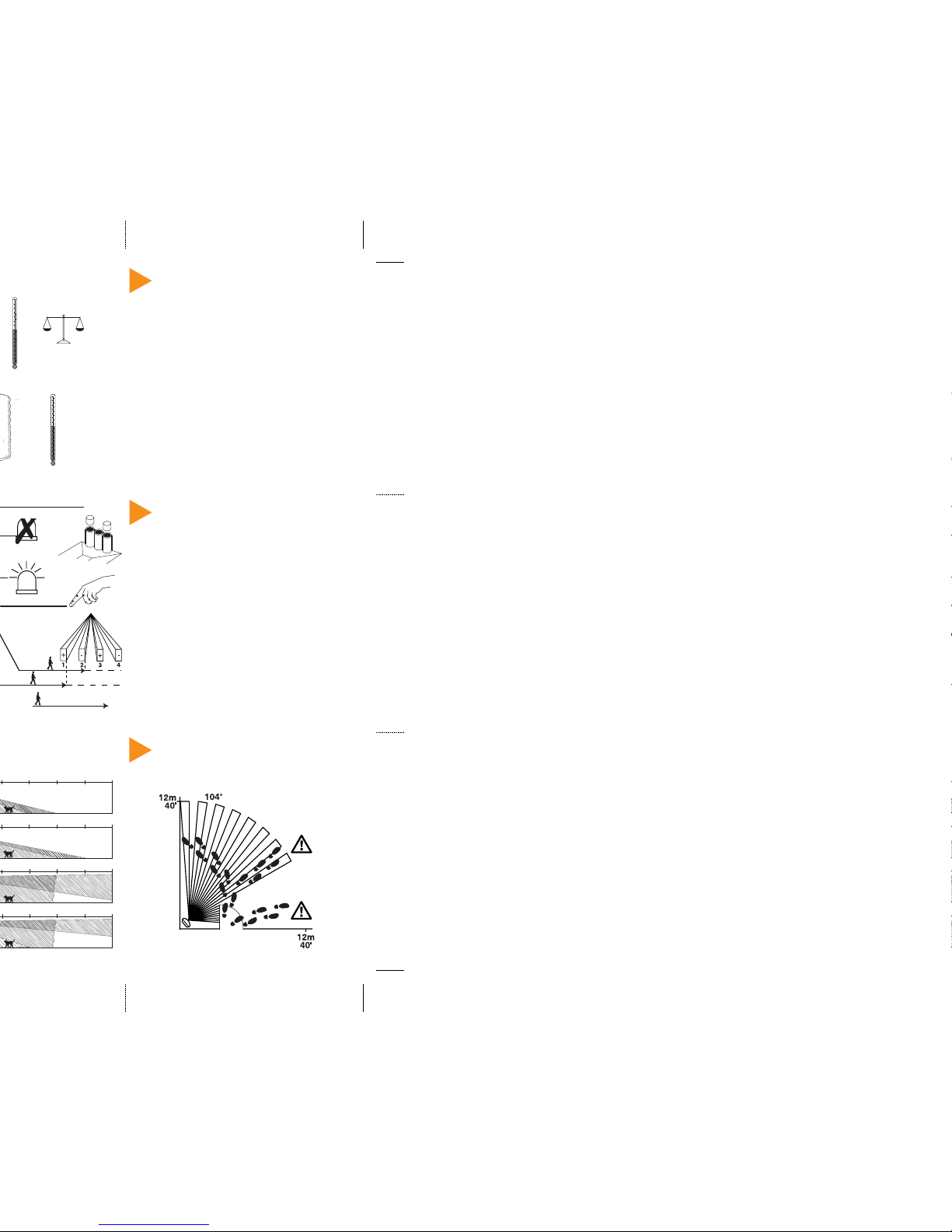
9 BEWARE OF OBSTRUCTIONS
✓
6m
19'8"8m26'2"
10m
32'9"
12m
40'0"
6m
19'8"8m26'2"
10m
32'9"
12m
40'0"
6m
19'8"8m26'2"
10m
32'9"
12m
40'0"
6m
19'8"8m26'2"
10m
32'9"
12m
40'0"
)
190g (7oz) approx.
3 STANDARDS & APPROVALS
System Standard: Suggested use: within a BS EN 50131-1 Grade 2 system.
Environmental Class II.
EMC: Independently certified to EN 50130-4 : 1996.
RF Immunity: No false alarm from 80MHz to 1GHz at 50V/m modulated,
equivalent to a 700W uniform transmittor at 3m (10ft).
Complies with BS EN 61000-4-3 : 1997.
Electrostatic Discharge: No false alarm up to 8kV
Complies with BS EN 61000-4-2 : 1995.
Fast Transient Immunity: No false alarm up to ±4kV.
Complies with BS EN 61000-4-4 : 1995.
High Energy Transient
Immunity: No false alarm up to ±2kV.
Complies with BS EN 61000-4-5 : 1995.
Conducted RF Susceptibility: No false alarm at 10Vrms.
Complies with BS EN 61000-4-6 : 1995.
Conducted Emissions: Complies with EN 55022 Class B.
Radiated Emissions: Complies with EN 55022 Class B.
Microwave Range: Internal pot to adjust.
Type Approvals: Complies with: MPT 1349, I-ETS 300 440, FCC Part 15.
0.3 - 3.0m/s
✗
5 REMOTE LED & LATCH INPUT
FUNCTIONS
The latch terminal (see Section 4) can perform several different functions
depending on how it is connected:
Latch connected to Set Positive (SW+, Set+): The LEDs will be disabled while
the system is set. Any detectors triggered while the system is set will indicate
this by permanently lighting the Alarm LED (upon unsetting the system).
Detectors can be reset by taking the latch line high and then low again.
Latch connected to Alarm Positive (AL+, A+ve): The first detector activated
while the system is set will indicate this with a slowly flashing Alarm LED
(upon unsetting the system). Detectors which activated subsequently will
indicate this by permanently lighting the Alarm LED. Detectors can be
reset by taking the latch line high and then low again.
The latch input is not suitable for use on entry/exit or walk through zones.
Remote LED: Connect RL to12V to disable the walk test LEDs.
Connect RL to 0V or leave unconnected to enable the walk test LEDs.
➞
➞
PULSE COUNT
LED OFF
LED ON
1 - 10ft/s
✗
✗
✓
✗
8
8
✓
✗
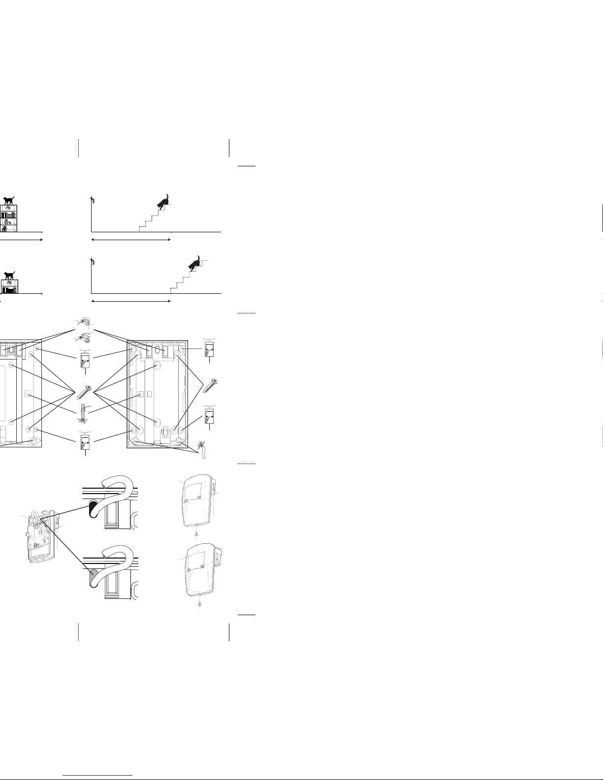
Seal all holes
7
4m
13'1"
A
B
C
4m
13'1"
✓
2m
6'7"
2m
6'7"
3m
9'10"
3m
9'10"
✗
✓
✗
 Loading...