

Texecom Medusa Installation Instructions Manual
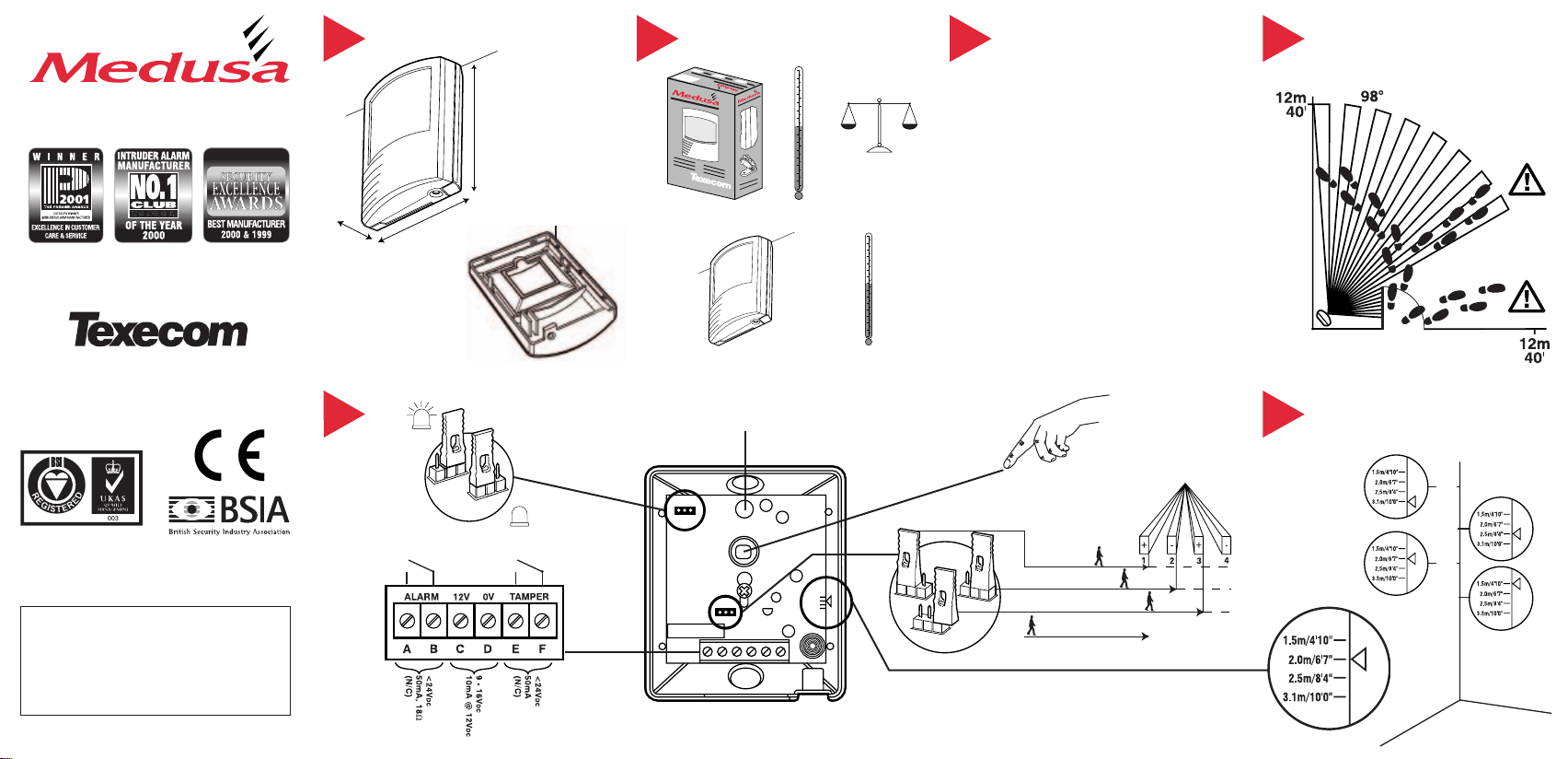
1 PHYSICAL
www.texe.com
www.texe.com
WINNER
✗
1.5m
(4'10")
2.5m
(8'4")
3.1m
(10'0")
2.0m
(6'7")
ukpanels.com
2 ENVIRONMENTAL 3 FALSE ALARM PROTECTION
4 COVERAGE AND PICK-UP
Passive Infrared Detector
INSTALLATION INSTRUCTIONS
THANK YOU FOR VOTING TEXECOM
Ask your distributor today for the new Texecom full colour
INS 001-5
Product Guide.
QUALITY ASSURANCE
Certificate Number: FM 35285
WARRANTY
5 year replacement warranty.
The Medusa is designed to detect the movement of an intruder
and activate an alarm control panel. As the Medusa is not a complete
alarm system, but only a part thereof, Texecom cannot accept
responsibility or liability for any damages whatsoever based on a claim
that the Medusa failed to function correctly.
Due to our policy of continuous improvement Texecom reserves
the right to change specification without prior notice. All specifications
are measured at 20˚C (68˚F).
Document Ref: M/EU/1.0-5
©1994 - 2004 Texecom Ltd
38mm
(1.5”)
5
67mm
(2.6”)
LED ON
79mm
(3.0”)
2.5mm (0.1”) ABS
LED OFF
-35°C (-31°F) to +60°C (+140°F)
-35°C (-31°F) to +55°C (+131°F)
WALK TEST LED
90g (3oz) approx.
PULSE COUNT
1
Design: Noise reduction circuits with maximum
RF Immunity: No false alarms from 80MHz to 1GHz at
Electrostatic Discharge: No false alarm up to 8kV.
Fast Transient Immunity: No false alarms up to ±1kV.
High Energy Transient
Immunity: No false alarm up to ±1kV. Complies with
Conducted RF
Susceptibility: No false alarms at 10Vrms. Complies with
EMC: Independently certified to EN 50130-4 : 1996.
Pulse Count: Adjustable Pulse Count. Internal link to select.
ground plane.
50V/m, equivalent to a 700W uniform
transmitter at 3m (10ft).
Complies with BS EN 61000-4-3 : 1997.
Complies with BS EN 61000-4-2 : 1995.
Complies with BS EN 61000-4-4 : 1995.
BS EN 61000-4-5 : 1995.
BS EN 61000-4-6 : 1996.
✗
DO NOT TOUCH
2
FAST
NORMAL
SLOW
0.3 - 3.0m/s
3
1 - 10ft/s
✓
6 MOUNTING HEIGHT AND
SETTINGS
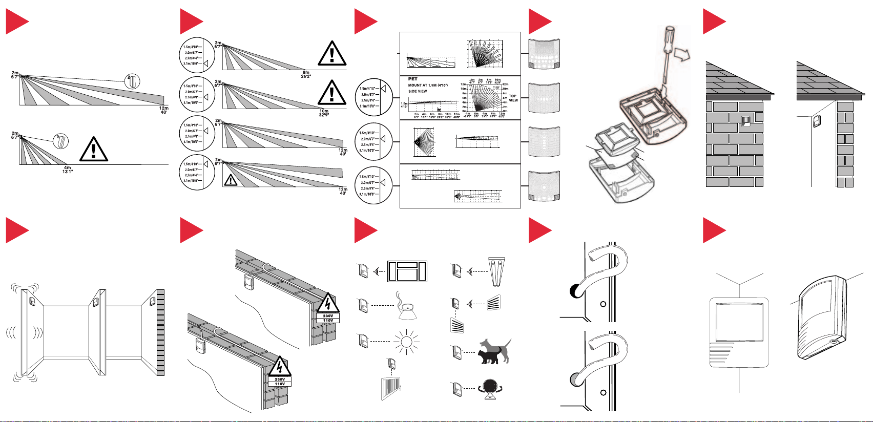
CURTAIN
TOP
VIEW
6°
SIDE
VIEW
12m
40'0"
2m
6'7"
0m
0'0"
4m
13'1"
12m
40'0"
6m
19'8"
4m
13'1"
10m
32'9"
8m
26'2"
2m
6'7"
6m
19'8"
10m
32'9"
2m
6'7"
4m
13'1"8m26'2"
2m
6'7"
0m
0'0"
LONG RANGE
SIDE
VIEW
TOP
VIEW
2m
6'7"
4m
13'1"
0m
0'0"
8°
12m
40'0"
16m
52'5"
20m
65'6"
24m
78'9"
28m
91'9"
32m
104'11"
6m
19'8"
4m
13'1"
10m
32'9"
14m
45'11"
18m
59'0"
22m
72'1"
26m
85'3"
30m
98'4"
34m
111'5"
8m
26'2"
2m
6'7"
2m
6'7"
4m
13'1"
0m
0'0"
12m
40'0"
16m
52'5"
20m
65'6"
24m
78'9"
28m
91'9"
32m
104'11"
6m
19'8"
4m
13'1"
10m
32'9"
14m
45'11"
18m
59'0"
22m
72'1"
26m
85'3"
30m
98'4"
34m
111'5"
8m
26'2"
2m
6'7"
VOLUMETRIC
TOP
VIEW
12m
40'0"
SIDE VIEW
2m
6'7"
12m
40'0"
6m
19'8"4m13'1"
10m
32'9"8m26'2"
2m
6'7"
4m
13'1"
0m
0'0"
-4m
-13'1"
8m
26'2"
6m
19'8"
10m
32'9"
2m
6'7"
-2m
-6'7"
2m
4m
6m
8m
10m
12m
2m
0m 0m
4m
6m
8m
10m
12m
98°
7 ANGLING THE DETECTOR 11 MOUNTING THE MEDUSA
✗
✗
✗
✗
✗
✗
✗
✗
ukpanels.com
8 COVERAGE AT 2m
9 LENS SELECTION
10 CHANGING LENSES
For indoor use only
See Mounting
Height Diagram
✓
(Section 6)
12 MOUNTING THE MEDUSA
Mount on a stable surface
✗
INS 001-5
✓
✓
13 WIRING
Do not run cable parallel to mains wiring
✓
✗
✓
14 CHOOSING A LOCATION
Avoid common false alarm sources
✗
LENS
LENS RETAINER
FACETS
15 SEAL ALL HOLES 16 MOUNTING WITHOUT
BRACKETS
✓
✗
✓
 Loading...