


Texecom LAIA5000 User Manual
Installation Manual
Premier Elite 32XPH-W
INS732

Premier Elite 32XPH-W Installation Instructions
2 INS732
1. Contents
1. Contents ............................................... 2
2. Premier Elite 32XPH-W ........................ 3
System Requirements .................................... 3
System Design Considerations ..................... 4
Multiple Expander Systems .............................. 4
Learning Devices ............................................. 4
Placing Devices ............................................... 4
3. Quick Start Guide ................................ 4
4. System Overview ................................. 5
Mounting the Expander.................................. 6
Wiring ............................................................. 6
Selecting an Address ..................................... 6
Ricochet Expander Addressing ..................... 7
Introduction ..................................................... 7
Example: Totally wireless system(s) ................. 7
5. Programming ....................................... 7
Premier Elite™ V2.10> 12/24/48/88/168
Ricochet Learn Menu ..................................... 7
Auto Zone Type & Area .................................. 8
Deleting Devices ............................................ 9
Summary of Keys used .................................. 9
Premier EliteV2.00 - V2.09 24/48/88/168 & 640
+ Ricochet V2.xx ............................................ 9
Introduction ..................................................... 9
Deleting Devices ............................................ 10
Device Modes of Operation............................ 10
Zone Types & Attributes................................. 11
Standalone Mode ......................................... 12
Standalone Operation .................................. 12
This table shows two example systems. ..... 13
6. Ricochet Diagnostics ......................... 13
Premier Elite V2.XX ...................................... 13
Devices .......................................................... 13
Interpreting Keypad Displays ......................... 13
Ricochet Diagnostics Menu ........................... 15
Premier Elite V3.XX ...................................... 16
Low signal security ........................................ 16
7. Modes of Operation ........................... 16
Commission Mode ....................................... 16
Expander ....................................................... 16
Device Commission Mode ............................. 16
8. System Attributes .............................. 17
Polling .......................................................... 17
System Devices ............................................ 17
Auto Mode ................................ ..................... 17
Always Awake ................................................ 17
Device Specific .............................................. 17
Hybrid Mode (V2.xx) ...................................... 17
Premier Elite 32XPH-W Power Loss ............ 18
9. Specifications .................................... 18
Electrical ........................................................ 18
Physical.......................................................... 18
Standards & Directives ................................... 18
Standards ...................................................... 18
FCC ID: MYJLAIA5000 .................................... 18
FCC warning statement: ................................. 18
Warranty......................................................... 19

Premier Elite 32XPH-W Installation Instructions
INS732 3
2. Premier Elite 32XPH-W
Texecom has developed a new method of wireless security signalling based on the concept of mesh
networking. Mesh-networking is the process whereby every single wireless device is capable of receiving and
retransmitting any signal from any other wireless device o n the network. The size, scalability and range of the
entire system are extended as wireless signalling is no longer limited by point-to point communications. The
range of a Ricochet® enabled wireless system is greater than previous systems, with multiple devices capable
of relaying messages to and from even the most remote locations in a building. Each Ricochet enabled
device provides signalling routes to and from control panels. If the wireless communication between devices
weakens, the Ricochet network ‘self-heals’ and automatically re-routes communications via alternate Ricochet
enabled devices. The reliability of the wireless system increases as more Ricochet devices are installed.
SignalSecurity™ further enhances network reliability with each device already aware of the number of
communication paths available to it.
Firmware versions prior to those listed are NOT compatible.
Control Panel
Premier Elite 32XPH-W
Legacy
Ricochet
Ricochet V2.xx
** V2.10 > Premier Elite
12/24/48/88/168 & 640*
See Section 3
N/A
V2.10>
V2.10>
Multiple Expander Support
It is now possible to add multiple expanders to the system allowing for greater flexibility in system design, and
also taking wireless capability to new levels.
Control Panel Capacity
The table below details the maximum number of expanders and devices that may be used on the different
control panels.
Panel
32XPH-W
Expanders
Devices
Premier Elite 12-W & Live™
N/A
N/A
Premier Elite 24™
1
16
Premier Elite 48™
1
32
Premier Elite 48-W™
N/A
32
Premier Elite 88™
2
64
Premier Elite 168™
4
128
Premier Elite 640™
16
512
Premier Elite 32XPH-W take 4 address slots on the network.
System Requirements
To enable all of the advanced functionality and diagnostics capability Ricochet the following are minimum
requirements:-
Wintex™ Version 6 Build 16 or later
Ricochet Monitor™ 0.2.15.00 or later
Premier Elite™ Series V2.xx or later
Premier Elite™ 32XPH-W Expanders V2.xx or later
Expander firmware version can be found on the round green sticker located on the RH side of the PCB.

Premier Elite 32XPH-W Installation Instructions
4 INS732
System Design Considerations
To ensure correct setup and operation of the Wireless Network it is important that the following procedures
are used when learning and placing devices.
Multiple Expander Systems
When using multiple expanders great care should be taken when designing the system. Each expander
should be treated as its own wireless network; it is not possible for devices to hop from o ne wireless network
to the other, it is also not possible for expanders to pass wireless signals from devices not assigned to them
and nor can the expanders talk to each other.
Learning Devices
All devices should be learnt before they are placed in their final location. The expander should be in
commission mode, please see page 16.This will ensure that they are registered on the receiver or control
panel, and that Mesh Networks and routing are established correctly. Please refer to the relevant section in
this document to Learn Devices to the system.
Devices should be at least 1Mtr away but ideally 10m from the receiver when being learned.
Placing Devices
Once all of the devices have been learnt, they will need placing in their desired location, this should be done
by installing devices closest to the expander first and then working outwards so that the last devices installed
are those furthest away from the expander.
Make sure to install devices with the expander in Commission mode. See page 16.
Devices also have a commission mode which will indicate a secure and valid path of communication to the
receiver. See page 16.
You should wait at least 20 minutes after installing the last device to make sure routing has been correctly
established between all system devices.
For maximum reliability and system integrity avoid long and thin s et-ups. Do not mount devices on or near metal.
Keep devices away from mains electricity supplies.
Devices are capable of hopping through up to two other devices, or a maximum of three hops.
3. Quick Start Guide
1. Connect Receiver to Control Panel Network & Leave Tamper Circuit Open. See Page 6
2. Ensure all Option Switches are off. See Page 5
3. Learn Devices to Control Panel. See Page 7 Onwards
4. set attributes. See Page 7 Onwards
5. Change Device Attributes according to application. See page 10
6. Place Devices in desired location, use LED to indicate Signal Security. See Page 4 & 16
7. Wait 20 Minutes for Mesh Network to establish
8. Walk Test System.
Premier Elite 32XPH-W Installation Instructions
INS732 5
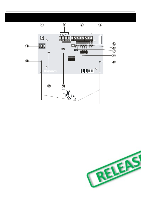
4. System Overview
1 2 3 4 5 6 7 8
1ON2 4
3
TX RX
NETWORK
ADDRESS
45 4 2 5 6 3 9 12581
TAMPER
DISABLE
1: Function Switch
Used to Learn devices in Standalone mode, and
to clear latched outputs.
2: Network Connection
The + and – terminals provide power whilst the T
and R terminals are transmit and receive data.
3: Outputs 1-8
Eight transistor outputs which can indicate the
status of nodes 1-16. See page 12 for details.
4: Comm. Port Connection
Serial communications port for connecting the
32XPH-W to a PC via PC Com/USB Com or Com
IP/WiFi for use with Ricochet Monitor Software.
5: Lid Tamper
When open puts the system into commission
mode and digitally attenuates the receiver signal
by 15Db.
6: Programming LED’s
Allows programming of devices directly to the
receiver, in conjunction with the learn switch
(Standalone mode only).
7: Tamper Disable
Disables the lid and rear tamper
8: RF LED
Flashes when transmitting or receiving RF data
9: Antenna
RF Antenna
10: Network LED’s
Green LED = Data received by the expander
from the panel Red LED = Data transmitted by
the expander to the panel. (The flash rate
depends on the mode and RF activity)
11: Heartbeat LED
Flashes steadily to indicate that the receiver is
functioning correctly. If the light is ON or OFF all
the time, then there could be a hardware
problem.
12: Address Switch/Option Switch (Standalone
Mode Only)
Used to assign the address of the receiver on the
network when connected to a control panel.
Options switches when used in Standalone
Mode.

Premier Elite 32XPH-W Installation Instructions
6 INS732
Mounting the Expander
Remove each screw cap by inserting a flat bladed screwdriver into the slot and turning anti-clockwise,
excessive force is NOT required. Remove both of the cover screws and put them in a safe place along with
the screw caps. Gently pull the cover away from the base applying slight pressure to the sides at the top of
the expander if required. The front cover should now be off. Mount the expander using at least two
appropriate countersunk screws (no larger than No. 8). A keyhole slot has been provided to assis t mounting
and aid levelling. If required a screw should be placed into the knockout on the rear of the expander to enable
the rear/wall tamper.
Do not mount near metal or mains supplies. When using with metal control panels a minimum of 50cm g ap is
required. Do not mount near aerials of any description, or other wireless equipment.
Wiring
It is strongly recommended that the system is completely powered down (mains and battery) before wiring
the expander. Connect the expander to the control panel using 4-core cable as follows:
Expander
Control Panel
Description + +
+12V Supply - -
0V Supply T T
Transmit Data R R
Receive Data
The networks are made up of four terminals incorporating power and data. To ensure correct operation, all
four terminals on the device must be connected to the corresponding terminals on the control panel or
previous device. Expanders can be connected using 4-core cable. However, it is recommended that 6 or 8core cable is used as the spare cores can be used to ‘Double Up’ on the power connections if needed.
Standard 7/0.2 alarm cable can be used for most installations. However, under certain conditions it may be
necessary to use screened cable.
Selecting an Address
Each expander must be assigned a different address using the D IL switches located on the PCB. The table
below shows the expander addressing:
Address
DIL 1
DIL 2
DIL 3
DIL 4
1
On or Off
Off
Off
Off
2 4 3
1
2
Off
On
Off
Off
2 4 3
1
3
Off
Off
On
Off
2 4 3
1
4
Off
Off
Off
On
2 4 3
1
5
On
Off
Off
On
2 4 3
1
6
Off
On
Off
On
2 4 3
1
7
Off
Off
On
On
2 4 3
1
8
On
Off
On
On
2 4 3
1
Never set two expanders on the same network to the same address. Expanders are factory set to address 1.