

Texecom LAHA5002, LAHA5001 User Manual
Installation Guide
Digital Transmitter Module
Ricochet® High Power Node
LAHA5001 - Integrated antenna
LAHA5002 - External antenna
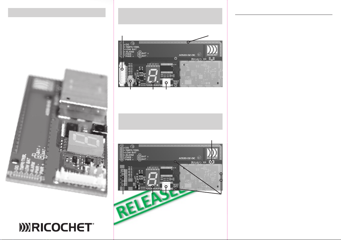
Digital Transmitter Module with
Integrated Antenna (DTM)
Wire Loom Connector
Battery
Connector
Test
Display
Test
Switch
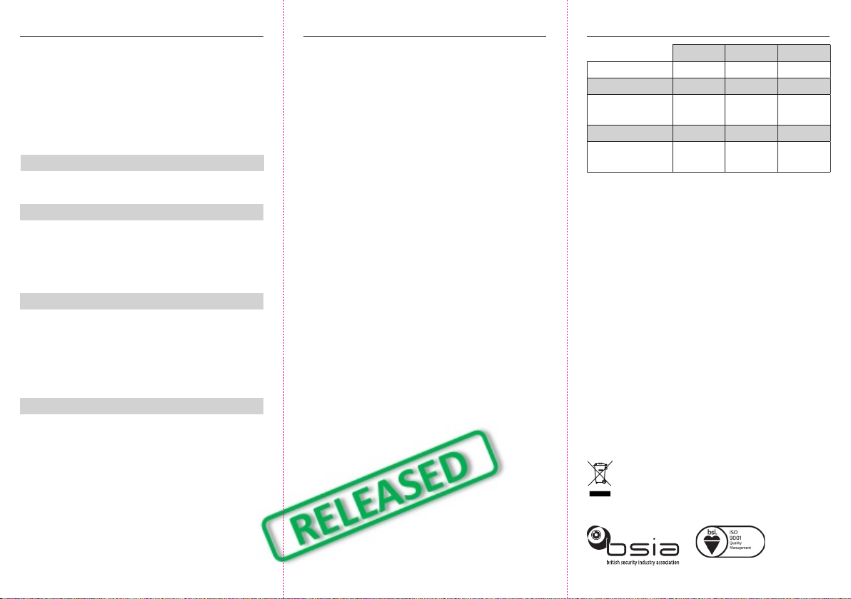
Digital Transmitter Module with
External Antenna (DTMA)
Connector for External Antenna
Integrated Antenna
Installation
• Install the unit and battery holder (if required)
inside the host unit using appropriate xings.
• Connect the required inputs from the host unit
using either the 10 way connector or the input
pin connections.
• For the DTMA, the antenna should be connected
and positioned away from metal obstacles and
the SMA connection must be secured with shrink
wrap sleaving or epoxy glue.
• To congure the device, insert the AA batteries
whilst holding down the test switch. The LED
display will ash showing the type of unit
currently congured.
• Using the test button, select the number for the
unit which the module has been installed in and
then hold the button down to select. The unit will
now attempt to learn to a Premier Elite 32XPH-W.
• The above selection will be retained when
changing the battery. To re-congure the unit,
repeat the above step. If changing the device
number, the device will need re-learning.
• When not changing the conguration, the learn
process is initiated by inserting the battery into
INS733
Input Pin
Connections
Test
Display
Test
Switch
Mounting
Points
Testing
To test the wireless link from the DTM back to the
Premier Elite 32XPH-W, install the module and press
the test button. The display will alternate top and
bottom segments while it attempts to communicate
with the Premier Elite 32XPH-W. If it is successful, it
will display the signal strengths (1-9) for each hop. If
it is unsuccessful, it will display an “F”.
Examples:
Display ashes 7, -, -
DTM has direct connection with the Premier Elite
32XPH-W, of strength 7.
Display ashes 8, 7, -
DTM is connected to the Premier Elite 32XPH-W
through 1 other device. The strength of the signal
between the DTM and the forwarding device is 8,
and between the forwarding device and Premier
Elite 32XPH-W is 7.
Display ashes 5, 8, 3
DTM is connected to the Premier Elite 32XPH-W
through 2 other devices. The strength of the
signal between the DTM and the rst device is 5,
between the rst device and the second device is
8, and between the second device and Premier Elite
32XPH-W is 3.
Display ashes F
DTM has no connection to the Premier Elite
32XPH-W.
When assembling a system, DTMs should be placed
and tested in order working outwards from the
Premier Elite 32XPH-W.
Note: Devices are unable to communicate when
they are less than 10m apart.
Approvals
This product is tested and approved to Federal
regulation 47 1A Part 15 Sub Part C as a modular
transmitter.
DTM : FCC ID: MYJLAHA5001
DTMA : FCC ID: MYJLAHA5002
The DTMA is ApproveD wiTh The use of The fMAG35153-sM-3K AnTennA AnD ufL
To sMA ADApTor. The sMA ADApTor when connecTeD shALL be shrinK wrAppeD or
GLueD wiTh epoxy To AvoiD The enD user connecTinG ALTernATive AnTennA Types.
Warning: Any Changes or modications not
expressly approved by the party responsible for
compliance could void the user’s authority to
operate the equipment.
When this product is installed within another
product and the module labelling is not visible then
the Product label must include:-
“Contains Transmitter Module FCC
ID:MYJLAHA500x”
Operation is subject to the following two conditions:
(1) This device may not cause harmful interference,
and (2) This device must accept any interference
received, including interference that may cause
undesired operation.
This equipment complies with FCC radiation
exposure limits set forth for an uncontrolled
environment. End users must follow the specic
operating instructions for satisfying RF exposure
compliance. This transmitter must not be
co-located or operating in conjunction with any
other antenna or transmitter.
The following warning notice must be included in
any product installation or user manual that the
module is a part of:-
“Any Changes or modications not expressly
approved by the party responsible for compliance
could void the user’s authority to operate the
equipment.”
Note: The device should not be used within 20cm
of the human body when the RF is enabled.
Specications
Min Nominal Max
Supply Voltage 2.5V 3.0V 3.6V
Current Draw 100uA 350mA
Operating
Frequency
920MHz 925MHz
Power Output 250mW
Max External
Antenna Gain
2.0dBi
Device Safety
• Do not expose any of the inputs or the power
supply to voltages above 3.6V.
• Do not install the unit outside unless it is inside a
detector or weatherproof enclosure.
• Ensure the product and battery holder are
securely installed inside host unit.
Battery Safety
• Do not throw into a re.
• Do not heat.
• Do not charge.
• Do not short circuit.
• Do not disassemble.
• Replace only with the same or equivalent type.
• Observe local regulations when disposing of
batteries.
Regulatory information
Supplier: Texecom Ltd, St. Crispin Way, Haslingden, Lancashire, BB4 4PW, UK.
Weee Directive: 2012/19/EU (WEEE directive): Products marked with this symbol
cannot be disposed of as unsorted municipal waste in the European
Union. For proper recycling, return this product to your local supplier
upon the purchase of equivalent new equipment, or dispose of it
at designated collection points. For more information see: www.
recyclethis.info.
Warranty: 1 year replacement warranty
FM 35285
© 2016 Texecom Ltd. www.te xe.com INS733
 Loading...