

Texecom GSM MODULE Installation Manual

GSM Module Installation Manual
GSM MODULE
Installation Manual
THANK YOU FOR VOTING TEXECOM
GSM Module Installation Manual
2 INS227
Introduction
The GSM module can be connected to the Premier 48/88/168 control panels to provide
the following facilities:
• Report system events (alarms, arm, disarm etc.) via text messaging to mobile
telephones
• Remotely arm, disarm and obtain current status of the alarm system via text
messaging
• High-speed modem communication for upload/download
•
Backup signalling path for Com300/2400 digital communicator
The GSM module is only supported on control panels fitted with software
version 3.0 or above.
The GSM module can only be used as a modem if the data service is
enabled by your network provider. Pay as you go tariffs generally do not
provide this feature.
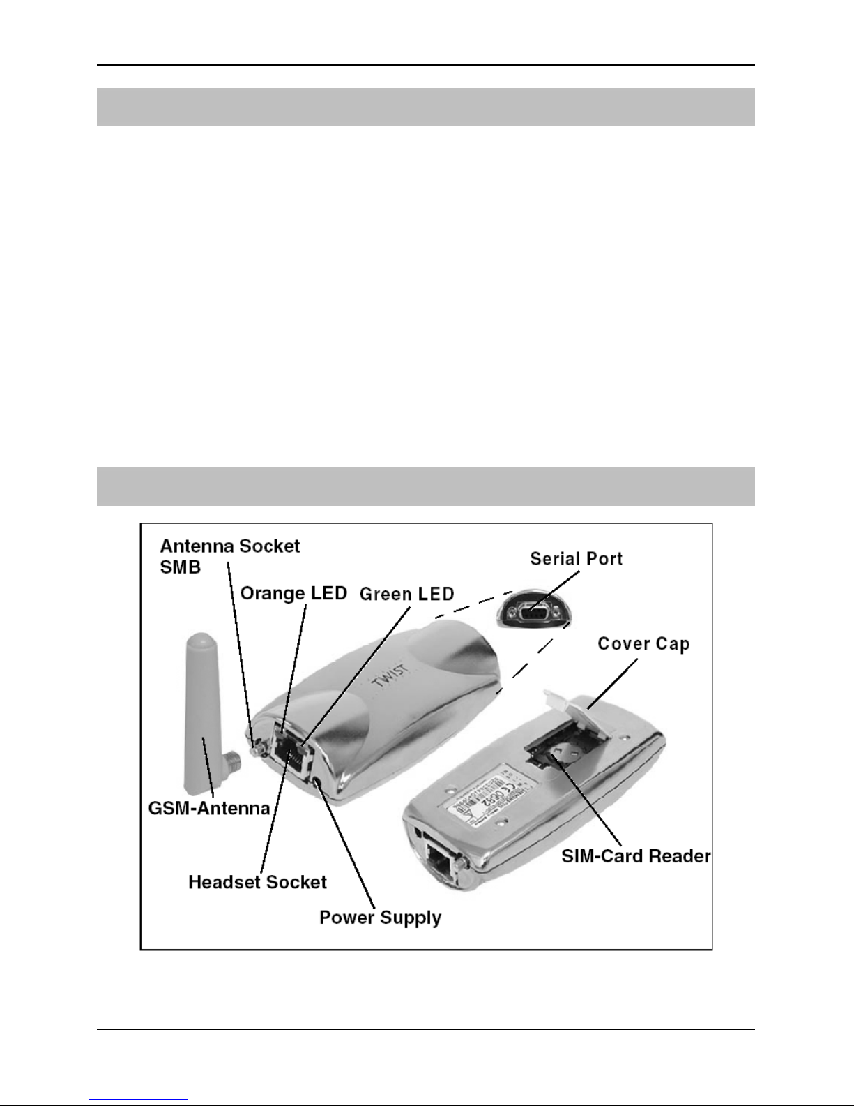
GSM Module Parts and Layout

GSM Module Installation Manual
INS227 3
GSM-Com Connectors and Layout
Connector Description
CON 1
This 2.1mm power plug should be plugged into the power socket on the GSM
module.
CON 2
This RJ45 type connector should be plugged into the RJ45 Headset socket on
the GSM module.
CON 3
This 7-way Molex type connector should be plugged onto Com 2 on the
Premier48/88/168 control panel.
CON 4
This 5-way Molex type connector should be plugged onto the AUDIO port on
the Premier Com300/2400 communicator (this is only required if you want to
use the GSM Module as a backup for the Com300/2400).
Installation
1. Insert the GSM antenna in the SMB socket of the GSM module.
2. Connect the RJ45 connector of the GSM-Com (CON 2) to the Headset socket of
the GSM module.
3. Open the cover cap on the underside of the GSM module:
 Loading...