

Texecom ComGSM Installation Manual

ComGSM Module Installation Manual
INSTALLATION
MANUAL
GSM Communicator Module
Issue 1
THANK YOU FOR VOTING TEXECOM
ComGSM Module Installation Manual
2 INS315
Introduction
The ComGSM module can be connected to the Premier 24/48/88/168/640 control
panels to provide the following facilities:
• Report system events (alarms, arm, disarm etc.) via text messaging to mobile
telephones
• Remotely arm, disarm and obtain current status of the alarm system via text
messaging
• High-speed modem communication for upload/download
The GSM module can only be used as a modem if the data service is
enabled by your network provider. Pay as you go tariffs generally do not
provide this feature.
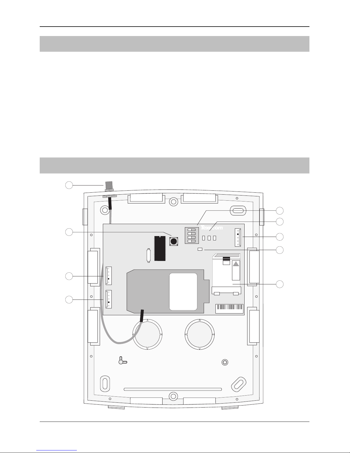
ComGSM Layout
1
PCG0123456
1
ON
2
3
4
3
Com1Engineer Keypad
4
Options
Audio
LOCK
123
5
2
6
7
9
8
ComGSM Module Installation Manual
INS315 3
Antenna connection
Tamper switch
Com1 data connection to Premier control panel
Engineer keypad connector (for future use)
Option switches (see table below)
Status LED’s (see table below)
Audio connector (for future use)
Heartbeat LED
SIM card socket
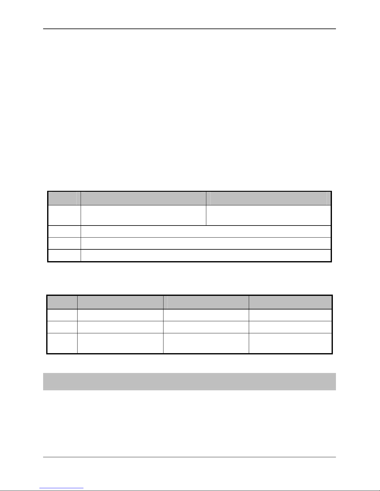
Option Switches
The option switches () function as follows:
Switch Off On
1
When the tamper is open, the GSM
signal is reported as NO signal
GSM signal level is reported as normal
2 For future use – leave in OFF position
3 For future use – leave in OFF position
4 Toggle to perform a Reset
Status LEDs
The three status LED’s () indicate the following:
LED Off On Flashing
1 GSM NOT Ready GSM Ready GSM Communicating
2 Panel NOT Ready Panel Ready Panel Communicating
3 No GSM Signal
Dim = Low Signal
Bright = Good Signal
N/A
Installation
The ComGSM module should be installed as close to the control panel as possible, so
that the harness lead supplied with the unit is able to plug onto the control panel
communication port.
1. Route the harness lead into the module housing using the top left cable
entry and plug the connector onto COM1 (
).
 Loading...