

Page 1

User’s Guide
UCC3817 BiCMOS Power Factor
Preregulator Evaluation Board
User’ s Gu ide
1
Page 2

SLUU077C – September 2000 – Revised November 2002
UCC3817 BiCMOS Power Factor Preregulator
Evaluation Board
Mike O’Loughlin Power Supply Control Products
Contents
1 Introduction 1. . . . . . . . . . . . . . . . . . . . . . . . . . . . . . . . . . . . . . . . . . . . . . . . . . . . . . . . . . . . . . . . . . . . . . . . .
1.1 Features 2. . . . . . . . . . . . . . . . . . . . . . . . . . . . . . . . . . . . . . . . . . . . . . . . . . . . . . . . . . . . . . . . . . . . . .
1.2 Description 2. . . . . . . . . . . . . . . . . . . . . . . . . . . . . . . . . . . . . . . . . . . . . . . . . . . . . . . . . . . . . . . . . . . . . .
2 Operating Guidelines 3. . . . . . . . . . . . . . . . . . . . . . . . . . . . . . . . . . . . . . . . . . . . . . . . . . . . . . . . . . . . . . . .
2.1 Step 1: Load Connections 4. . . . . . . . . . . . . . . . . . . . . . . . . . . . . . . . . . . . . . . . . . . . . . . . . . . . . . . . .
2.2 Step 2: Applying Input Power 4. . . . . . . . . . . . . . . . . . . . . . . . . . . . . . . . . . . . . . . . . . . . . . . . . . . . . .
2.3 Step 3: Measuring the Evaluation Board’s Performance 4. . . . . . . . . . . . . . . . . . . . . . . . . . . . . . .
3 Evaluation Board Layouts 4. . . . . . . . . . . . . . . . . . . . . . . . . . . . . . . . . . . . . . . . . . . . . . . . . . . . . . . . . . . .
4 Evaluation Board Components 5. . . . . . . . . . . . . . . . . . . . . . . . . . . . . . . . . . . . . . . . . . . . . . . . . . . . . . .
5 Typical Performance 6. . . . . . . . . . . . . . . . . . . . . . . . . . . . . . . . . . . . . . . . . . . . . . . . . . . . . . . . . . . . . . . . .
6 Additional Information 7. . . . . . . . . . . . . . . . . . . . . . . . . . . . . . . . . . . . . . . . . . . . . . . . . . . . . . . . . . . . . . .
2
UCC3817 BiCMOS Power Factor Preregulator
Page 3

SLUU077C – September 2000 – Revised November 2002
1 Introduction
This user’s guide details the Texas Instruments (TI) UCC3817–EVM BiCMOS Power Factor Preregulator
Evaluation Module (EVM) SLUU077. It includes a list of EVM features, a brief description of the module
illustrated with pictorial and schematic diagrams and EVM specifications.
The UCC3817 evaluation board is designed to illustrate the performance of the controller in a 250 W boost
converter with power factor correction. The board is designed to handle a universal input operating voltage
range (i.e. 85–265 V ac) with a regulated 385 V dc output.
Proper precautions must be taken
when working with the board
CAUTION:
D High voltage levels are present on the evaluation board whenever it is energized.
D The output capacitor has high levels of energy storage and it must be discharged before the load is removed.
Improper handling of the evaluation board could cause serious injury.
D It is important to maintain the ambient temperature around the evaluation board to below 40°C during
operation
1.1 Evaluation Module Features
D
Designed for Compliance with IEC 1000-3-2 (Low Total Harmonic Distortion)
D Worldwide Line Operation 85 V
RMS
to 265 V
RMS
D Regulated 385-V, 250-W(max), dc Output
D Accurate Power Limiting
D Accurate Overvoltage Protection
1.2 Description
The UCCx817 provides all the functions necessary for active power-factor-corrected preregulators. The
controller achieves near-unity power factor by shaping the ac input-line current waveform to correspond to that
of the ac input-line voltage. Average current-mode control maintains stable, low-distortion, sinusoidal line
current.
The controller’s operation is similar to previously designed Unitrode preregulators with an added feature to
reduce the RMS-current in the boost capacitor. The controller uses leading-edge modulation that, when
synchronized properly with a downstream dc-to-dc converter, reduces the RMS current in the boost capacitor.
UCC3817 BiCMOS Power Factor Preregulator
3
Page 4
SLUU077C – September 2000 – Revised November 2002
V
LINE
85–265
V
RMS
AC2
AC1
IAC
F1
C14
1.5µF
400 V
R21
383
k
R16
Ω
R8 12
Ω
k
D6
100
C13
0.47µF
600 V
R14
0.25Ω5
W
R9
4.02
Ω
k
C8 270 pF
R15
51
Ω
k
R10
4.02
Ω
k
(OPTIONAL)
C9 1.2 nF
C7 150 nF
R7
100
Ω
k
C6 2.2µF
R6 30
C15
3.3µF
Ω
k
SEE EVM WARNINGS
AND RESTRICTIONS
VCC
R13
383
Ω
Ω
k
D3
6 A
600 V
R12
2
Ω
k
R11
10
Ω
k
V
REF
(OPTIONAL)
C10
1µF
D7
D8
L1
1 mH
HIGH VOLTAGE –
1
2
IAC
3
4
5
6
7
8
PKLIMIT
CAOUT
CAI
MOUT
IAC
VAOUT
VFF
D5
C11
1µF
D2
8 A, 600 V
UCC3817
VCC
CT
SS
RT
VSENSE
OVP/EN
VREF
HIGH TEMPERATURE –
SEE EVM WARNINGS
AND RESTRICTIONS
Q1
R17
D4
R3 20
Ω
k
VREF
20
C5 1µF
16GND DRVOUT
15
14
13
12
11
10
9
NOTE: High-Voltage component. See EVM Warnings and Restrictions at the back of this document.
NOTE: High-Temperature component. See EVM Warnings and Restrictions at the back of this document.
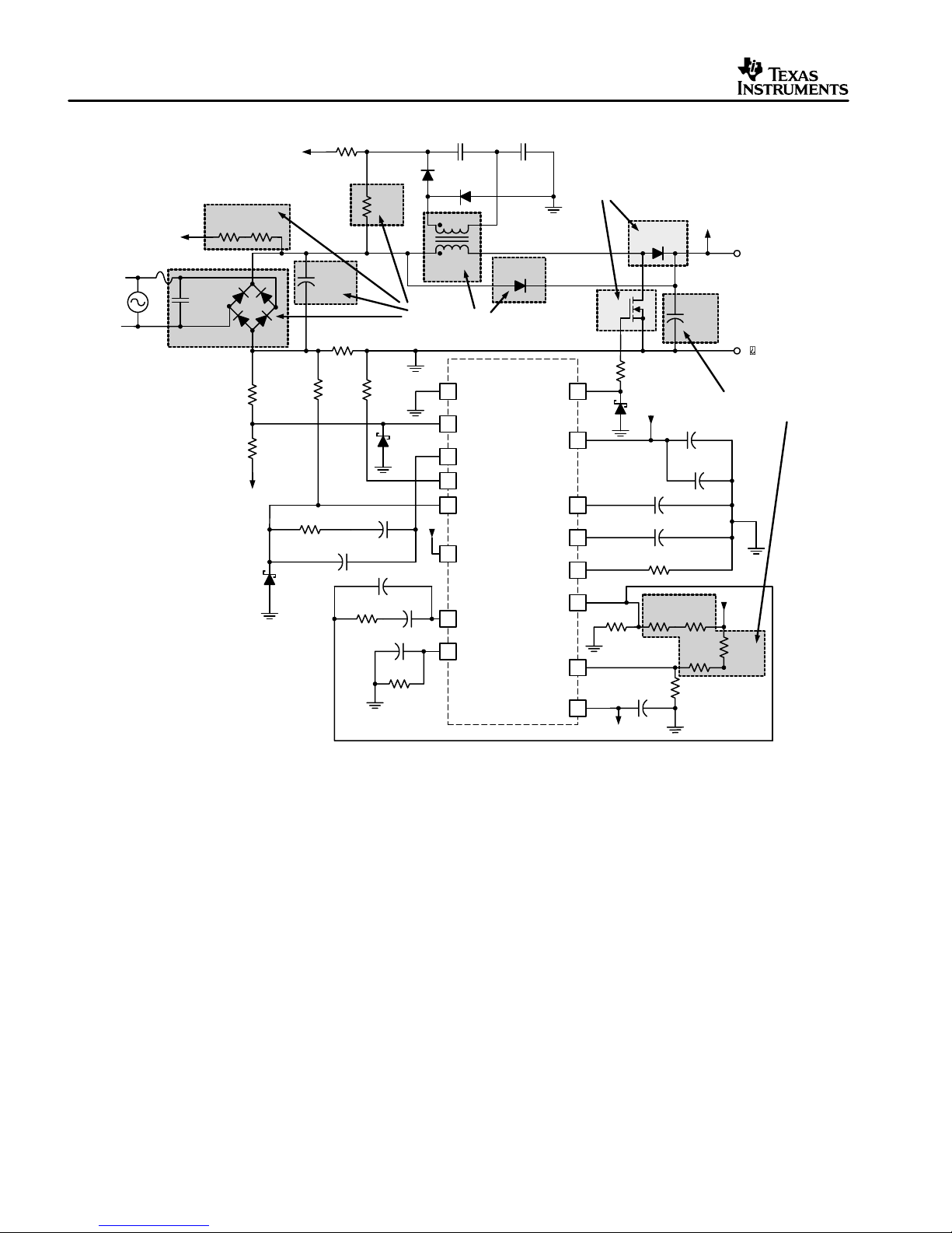
Figure 1. Evaluation Board Schematic
D1
6 A, 600 V
Ω
VCC
C1 560 pF
C4 0.01µF
R1 12
Ω
k
R2
499
Ω
k
V
C12
220µF
450 V
C3
1µF CER
C2
100µF AI EI
R19
499
Ω
k
R20
274
Ω
k
R5 10
Ω
k
O
V
O
+
V
OUT
385V
DC
GND
HIGH VOLTAGE –
SEE EVM WARNINGS
AND RESTRICTIONS
V
O
R4
249
Ω
k
UDG-01001
2 Operating Guidelines
The operating guidelines for the evaluation board are provided with reference to the schematic in Figure 1.
NOTE: In order for the output voltage to regulate, a load of 10 W must be applied to the evaluation
board’s output. In order to maintain power factor near unity , the voltage loop is designed with a slow
frequency response. Large transient steps in output current can cause the evaluation module to go
out of regulation.
4
UCC3817 BiCMOS Power Factor Preregulator
Page 5

SLUU077C – September 2000 – Revised November 2002
2.1 Step 1. Load Connections
A resistive or electronic load should be applied to the output connections of VO and GND.
NOTE: For safety reasons the load should be connected before power is supplied to the evaluation
board.
2.2 Step 2. Applying Input Power
A 50- or 60-Hz ac power source not exceeding 265 V
needs be applied across terminals AC1 and AC2 for
RMS
proper operation.
2.3 Step 3. Measuring the Evaluation Board’s Performance
With the ac source set between 85 V
current should track the input-voltage shape with near-unity power factor. The operation of the circuit is verified
over the line and load range and shows efficiency in the 90–95% range. At lighter loads, there may be some
distortion in the line current due to DCM operation. Please refer to Figure 3 and Figure 4 for typical evaluation
board performance.
RMS
and 265 V
, the output voltage should be regulated and the input
RMS
3 Evaluation Board Layouts
R18
R15
D7
D2
R14
HS1
D1
Q1
V0
GND
HIGH TEMPERATURE
SEE EVM WARNINGS
AND RESTRICTIONS
HIGH VOLTAGE
SEE EVM WARNINGS
AND RESTRICTIONS
D8
AC2
XC12
AC1
XL1
L1
C13
UCC3817 EVALUATION BOARD
NOTE: High-Voltage component. See EVM Warnings and Restrictions at the back of this document.
NOTE: High-Temperature component. See EVM Warnings and Restrictions at the back of this document.
Figure 2. UCC3817 Evaluation Board Layout Assembly
FA1
C12
C10
C11
R21
D3
R13
R12
R11
R8
D5 D6
R10
R16
R9
C9
C8
C15
C6
U1
C14
C7
R7
R6
C2
C3
C5
R20
GND
R17
D4
VCC
R22
C1
C4
SYNC
R1
R2
R19
R3
R4
R5
HIGH VOLTAGE
SEE EVM WARNINGS
AND RESTRICTIONS
UCC3817 BiCMOS Power Factor Preregulator
5
Page 6

SLUU077C – September 2000 – Revised November 2002
Ca acitors
Resistors
4 Evaluation Board Components
. Bill of Materials
Reference Qty DESCRIPTION Manufacturer Part Number
C1 1 560 pF, 50 V, ceramic Panasonic ECU–S1H561JCA
C2 1 100 µF, 25 V, electronic Panasonic EEU–FC1V101S
C3, C5 2 1 µF, 50 V, ceramic Panasonic ECU–S1H105MEB
C4 1 0.01 µF, 50 V, ceramic Panasonic ECU–S1H103KBA
C6, C15 2 2.2 µF, 50 V, ceramic Panasonic ECU–S1H225MEB
C7 1 150 nF, 50 V, ceramic, ±10% Panasonic ECU–S1H154KBB
Capacitors
Diodes
Fuses
Heat Sink
Inductors L1 1 1 mH, 5.5 A, 20:1 TR
MOSFETs Q1 1 International Rectifier IRFP450
Resistors
C8
C9 1 1.2 nF, 50 V, ceramic, ±10% Panasonic ECU–S1H122JCB
C10, C11 2 1 µF, 50 V, stacked metal poly Panasonic ECQ–V1H105JL
C12 1 220 µF, 450 V electronic Panasonic ECO–S2WB221DA
C13 1 0.47 µF, 600 V (optional for user, not used on EVM) Panasonic ECQ–E6474KF
C14 1 1.5 µF, 400 V Poly Panasonic ECW–F4155JB
C16 1 Not used Panasonic ECU–S2A330JCA
D1 1 6 A, 600 V, ultra fast diode International Rectifier HFA08TB60
D2 1 8 A, 600 V, 400 A surge General Instruments GI756CT
D3 1 6 A, 600 V, bridge General Instruments PB66
D4, D5,
D7, D8
D6 1 100 mA, 20 V, schottky BAT85
D9 1 Not used
F1 1 6 A, 250 V, 3 AG glass fast acting cartridge type
FH1, FH2
HS1 1 Heat sink for Q1 Aavid 513201
HS2
R1 1 12.1 kΩ, 1/4 W
R3 1 20 kΩ
R4 1 249 kΩ
R5, R11 2 10 kΩ
R6 1 30.1 kΩ
R7 1 100 kΩ
R8
R9, R10 2 4.02 kΩ
R12 1 2 kΩ
R13, R21 2 383 kΩ
R14 1 0.25 Ω, 3 W
R15, R18 2 24 kΩ, 1W, metal oxide/metal film Panasonic ERG 1S G 243
R16 1 100 Ω
1 270 pF, 50 V, ceramic, ±10% Panasonic ECU–S1H271JCA
4 1 A, 40 V, schottky 1N5819
2 3AG fuse clip
1 Heat sink for D1 Aavid 579302 B 0 00 00
Cooper Electronic
Technologies
1 12.1 kΩ
CTX08–13679–02
6
UCC3817 BiCMOS Power Factor Preregulator
Page 7

SLUU077C – September 2000 – Revised November 2002
Resistors
Hardware
Reference Qty DESCRIPTION Manufacturer Part Number
R17 1 20 Ω
R18 1 24 kΩ, 1W, metal oxide/metal film ERX 1S G 243
Resistors
Integrated
Curcuit
Sockets X @ U1 1 16 pin DIP socket
Board PCB 1 UCC3817 BARE PC BOARD
Hardware
NOTE: Unless otherwise specified, all resistors are 0.25 W metal film with a 1% tolerance.
R2, R19
R20 1 274k
R22 1 Zero Ohm jumper or 26AWG wire
U1 1 UCC3817N Texas Instruments UCC3817N
X1 @ Q1 1 Thermal Pad Silicone TO220
X2 @ HS1
X3 @ HS1 1 Nut #6X32
2 499 kΩ
1 Screw Pan Hd #6–32 X 3/8
5 Typical Performance
EFFICIENCY vs. OUTPUT POWER
100
VIN = 265 V
95
VIN = 175 V
90
Efficiency (%)
85
80
75
25 50 75 100 125 150 175 200 225 250
VIN = 85 V
P
– Output Power – W
OUT
Figure 3.
UCC3817 BiCMOS Power Factor Preregulator
7
Page 8

SLUU077C – September 2000 – Revised November 2002
POWER FACTOR
OUTPUT POWER
1.1
VIN = 85 V
1.0
vs.
0.9
0.8
0.7
Power Factor
0.6
0.5
0.4
25 50 75 100 125 150 175 200 225 250
VIN = 175 V
VIN = 265 V
P
– Output Power – W
OUT
Figure 4.
6 Additional Information
For more information, pin description and specifications for the UCC3817 PFC Controller, please refer to the
UCC3817 datasheet, TI Literature Number SLUS395, or contact the Texas Instruments Semiconductor Product
Information Center at 1–800–336–5236 or 1–972–644–5580. Product information can also be found on the at
http://www.ti.com.
This evaluation module can also be used to evaluate the performance of the UCC3818 PFC control IC by
removing R16 and applying the bias voltage to the VCC pin through a separate bias supply.
8
UCC3817 BiCMOS Power Factor Preregulator
Page 9

SLUU077C – September 2000 – Revised November 2002
DYNAMIC WARNINGS AND RESTRICTIONS
It is important to operate this EVM within the input voltage range of 85 V to 265 V ac and the output voltage of
385 V +/– 10%.
Exceeding the specified input range may cause unexpected operation and/or irreversible damage to the EVM.
If there are questions concerning the input range, please contact a TI field representative prior to connecting
the input power.
Applying loads outside of the specified output range may result in unintended operation and/or possible
permanent damage to the EVM. Please consult the EVM User’s Guide prior to connecting any load to the EVM
output. If there is uncertainty as to the load specification, please contact a TI field representative.
During normal operation, some circuit components may have case temperatures greater than 50°C. The EVM
is designed to operate properly with certain components above 50°C as long as the input and output ranges are
maintained. These components include but are not limited to linear regulators, switching transistors, pass
transistors, and current sense resistors. These types of devices can be identified using the EVM schematic
located in the EVM User’s Guide. When placing measurement probes near these devices during operation,
please be aware that these devices may be very warm to the touch.
Mailing Address:
Texas Instruments
Post Office Box 655303
Dallas, Texas 75265
Copyright 2001, Texas Instruments Incorporated
UCC3817 BiCMOS Power Factor Preregulator
9
Page 10

IMPORTANT NOTICE
Texas Instruments Incorporated and its subsidiaries (TI) reserve the right to make corrections, modifications,
enhancements, improvements, and other changes to its products and services at any time and to discontinue
any product or service without notice. Customers should obtain the latest relevant information before placing
orders and should verify that such information is current and complete. All products are sold subject to TI’s terms
and conditions of sale supplied at the time of order acknowledgment.
TI warrants performance of its hardware products to the specifications applicable at the time of sale in
accordance with TI’s standard warranty . Testing and other quality control techniques are used to the extent TI
deems necessary to support this warranty . Except where mandated by government requirements, testing of all
parameters of each product is not necessarily performed.
TI assumes no liability for applications assistance or customer product design. Customers are responsible for
their products and applications using TI components. T o minimize the risks associated with customer products
and applications, customers should provide adequate design and operating safeguards.
TI does not warrant or represent that any license, either express or implied, is granted under any TI patent right,
copyright, mask work right, or other TI intellectual property right relating to any combination, machine, or process
in which TI products or services are used. Information published by TI regarding third–party products or services
does not constitute a license from TI to use such products or services or a warranty or endorsement thereof.
Use of such information may require a license from a third party under the patents or other intellectual property
of the third party , or a license from TI under the patents or other intellectual property of TI.
Reproduction of information in TI data books or data sheets is permissible only if reproduction is without
alteration and is accompanied by all associated warranties, conditions, limitations, and notices. Reproduction
of this information with alteration is an unfair and deceptive business practice. TI is not responsible or liable for
such altered documentation.
Resale of TI products or services with statements different from or beyond the parameters stated by TI for that
product or service voids all express and any implied warranties for the associated TI product or service and
is an unfair and deceptive business practice. TI is not responsible or liable for any such statements.
Mailing Address:
Texas Instruments
Post Office Box 655303
Dallas, Texas 75265
Copyright 2002, Texas Instruments Incorporated
Page 11

Mouser Electronics
Authorized Distributor
Click to View Pricing, Inventory, Delivery & Lifecycle Information:
Texas Instruments:
UCC3817EVM
 Loading...