

Page 1

TMS320DM357 DVEVM v2.05
Getting Started Guide
Literature Number: SPRUGH0
December 2008
Printed on Recycled Paper
Page 2

IMPORTANT NOTICE
Texas Instruments Incorporated and its subsidiaries (TI) reserve the right to make corrections, modifications,
enhancements , improv ements , and ot her chang es to it s product s and services a t any time and to discontinue any
product or service without notice. Customers should obtain the latest relevant information before placing orders
and should verify that such information is current and complete. All products are sold subject to TI's terms and
conditions of sale supplied at the time of order acknowledgment.
TI warrants pe rformance of i ts hardware products to the speci fications appl icable at the time of sal e in accordanc e
with TI's standard w arranty . T esting and other quali ty control techniques are used to the extent TI deems necessary
to support this warranty. Except where mandated by government requirements, testing of all parameters of each
product is not necessarily performed.
TI assumes no li ability for a pplications assi stance or customer produc t design. Custom ers are responsibl e for their
products and applications using TI components. To minimize the risks associated with customer products and
applications, customers should provide adequate design and operating safeguards.
TI does not warrant or represent that any license, either express or implied, is granted under any TI patent right,
copyright, mask work right, or o ther TI inte llect ual property right rela ting to an y com binati on, machin e, or proces s
in which TI products or services are used. Information published by TI regarding third-party products or services
does not constitute a license from TI to use s uch prod uct s or servic es or a warranty or en dorsem ent there of. Use
of such information may r equ ire a l ice ns e from a thi rd p a r ty un der the p atents or other in tel lec tu al pro per ty of the
third party, or a license from TI under the patents or other intellectual property of TI.
Reproduction o f informa tion in T I dat a books or dat a sheet s is permissible only i f reproduc tion is without alteratio n
and is accompanied by all associated warranties, conditions, limitations, and notices. Reproduction of this information with alteration is an unfair and de ce ptiv e b us ine ss prac ti ce. TI is not responsib le or liable for such al tere d
documentation.
Resale of TI products or services with statements different from or beyond the parameters stated by TI for that
product or servic e voids all exp res s a nd any implied wa rran tie s for the associa ted TI p r od uct or se rvice and is an
unfair and deceptive business practice. TI is not responsible or liable for any such statements.
Following are UR Ls where y ou c an obtain informati on on other Texas Instruments product s and application s ol utions:
Products Applications
Amplifiers amplifier.ti.com Audio www.ti.com/audio
Data Converters dataconverter.ti.com Automotive www.ti.com/automotive
DSP dsp.ti.com Broadband www.ti.com/broadband
Interface interface.ti.com Digital Control www.ti.com/digitalcontrol
Logic logic.ti.com Military www.ti.com/military
Power Mgmt power.ti.com Optical Networking www.ti.com/opticalnetwork
Microcontrollers microcontroller.ti.com Security www.ti.com/security
Low Power Wireless www.ti.com/lpw Telephony www.ti.com/telephony
Video & Imaging www.ti.com/video
Wireless www.ti.com/wireless
Mailing Address: Texas Instruments
Post Office Box 655303 Dallas, Texas 75265
Copyright © 2008, Texas Instruments Incorporated
Page 3

EVALUATION BOARD/KIT IMPORTANT NOTICE
Texas Instruments (TI) provides the enclosed product(s) under the following conditions:
This evaluation board/kit is intended for use for ENGINEERING DEVELOPMENT, DEMON-
STRA TION, OR EVALUATION PURPOSES ONLY and is not considered by TI to be a finished
end-product fit for general consumer use. Perso ns handling the product(s) m ust have electronics
training and observe good engineering practice standards. As such, the goods being provided
are not intend ed to be compl ete in terms of required de sign-, marke ting-, and/or m anufactur ingrelated protecti ve considerations, including produ ct safety and environmental measures typically
found in end prod uc t s t hat i nc orpo rate such semiconductor c om po nen ts or circuit board s. T his
evaluation board/kit does not fall within the scope of the European Union directives regarding
electromagnetic comp atibility , restricted substances (RoHS), rec ycling (WEEE), FCC, CE or UL,
and therefore may not meet the technical requirements of these directives or other related
directives.
Should this evaluation board/kit not meet the specifications indicated in the User's Guide, the
board/kit may b e returned with in 30 days from the d ate of deliv ery fo r a ful l refun d. THE FO REGOING WARRANTY IS THE EXCLUSIVE WARRANTY MADE BY SELLER TO BUYER AND
IS IN LIEU OF ALL OTHER WARRANTIES, EXPRESSED, IMPLIED, OR STATUTORY, INCLUDING ANY WARRANTY OF MERCHANTABILITY OR FITNESS FOR ANY PARTICULAR
PURPOSE.
The user assumes all responsibility and liability for proper and safe handling of the goods.
Further, the user indemnifies TI from all claims arising from the handling or use of the goods.
Due to the open construction of the product, it is the user's responsibility to take any and all
appropriate precautions with regard to electrostatic discharge.
EXCEPT TO THE EXTENT OF THE INDEMNITY SET FORTH ABOVE, NEITHER PARTY
SHALL BE LIABLE TO THE OTHER FOR ANY INDIRECT, SPECIAL, INCIDENT AL, OR CONSEQUENTIAL DAMAGES.
TI currently deals w i th a v ari ety of cus tom ers for pro du ct s , an d the r efo re ou r arra ngement with
the user is not exclusive.
TI assumes no liability for applications assistance, customer product design, software
performance, or infringement of patents or services described herein.
Please read the U ser's Guide and, specificall y, the W arnings and Restric tions notice in the User's
Guide prior to handling the product. This notice contains important safety information about
temperatures and voltages. For ad ditional informatio n on TI's environmental and/or sa fety pro grams, please contact the TI application engineer or visit www.ti.com/esh.
No license is granted un der an y pa tent right or other intel lectu al proper ty rig ht of TI cove ring or
relating to any machine, process, or combination in which such TI products or services might
be or are used.
Mailing Address:
Texas Instruments
Post Office Box 655303
Dallas, Texas 75265
Copyright © 2008, Texas Instruments Incorporated
Page 4

FCC Warning
This evaluation board/kit is intended for use for ENGINEERING DEVELOPMENT, DEMONSTRA TION, OR EVALUATION PURPOSES ONLY and is not considered by TI to be a finished
end-product fit for general consumer use. It generates, uses, and can radiate radio frequency
energy and has not been tested for compliance with the limits of computing devices pursuant
to part 15 of FCC rules, which are designed to provide reasonable protection against radio
frequency interfere nce. Operation of this eq uip me nt in other environments ma y c aus e in terfe rence with radio co mm un ic atio ns , in w hi ch cas e the use r at his ow n ex pe nse w il l be req uire d t o
take whatever measures may be required to correct this interference.
Page 5

About This Guide
The DVEVM (Dig ital Video Ev al uat ion Mo dul e) i s an e valua tio n pl atform
that showcases the DaVinci architecture and lets users evaluate the
power and performance of DaVinci as a Multimedia engine.
This guide gives you overview information about the board and the
software provided with the board. It is intended to be used as an
introductory docum ent for the DVEVM. Other do cuments provide more
in-depth information. See the DVEVM documentation section of the
release notes fo r a complete l ist of docum ents that have b een include d
with the product.
Notational Conventions
This document uses the following conventions:
Preface
❏ Program listings, program examples, and interactive displays are
shown in a mono-spaced font. Exampl es us e bold for emphasis,
and interactive displays use bold to distinguish commands that you
enter from items that the system displays (such as prompts,
command output, error messages, etc.).
❏ Square brackets ( [ and ] ) identify an option al paramete r. If you use
an optional parameter, you specify the information within the
brackets. Unless the square br ack ets a re i n a bold ty pefac e, do no t
enter the brackets themselves.
v
Page 6
Trademarks
Trademarks
The Texas Instruments logo and Texas
Instruments are registered trademarks of Texas
Instruments. Trademarks of Texas Instruments
include: TI, DaVinci, the DaVinci logo, XDS, Code
Composer, Code Composer Studio, Probe Point,
Code Explorer, DSP/BIOS, RTDX, Online DSP
Lab, DaVinci, TMS320, TMS320C54x,
TMS320C55x, TMS320C62x, TMS320C64x,
TMS320C67x, TMS320C5000, and
TMS320C6000.
MS-DOS, Windows, and Windows NT are trademarks of Microsoft
Corporation.
UNIX is a registered trad emark of The O pen Grou p in the Un ited States
and other countries.
Linux is a registered trademark of Linus Torvalds.
Solaris, SunO S, and Java are trademarks or r egistered trademarks of
Sun Microsystems, Inc.
All other brand, produc t names, and service names are trademark s or
registered trademarks of their respective companies or organizations.
December 15, 2008
vi
Page 7

Contents
1 DVEVM Overview . . . . . . . . . . . . . . . . . . . . . . . . . . . . . . . . . . . . . . . . . . . . . . . . . . . . . . . . . . .1-1
This chapter introduces the DVEVM (Digital Video Evaluation Module).
1.1 What’s in this Kit?. . . . . . . . . . . . . . . . . . . . . . . . . . . . . . . . . . . . . . . . . . . . . . . . . . . . . .1-2
1.2 What’s on the Board?. . . . . . . . . . . . . . . . . . . . . . . . . . . . . . . . . . . . . . . . . . . . . . . . . . .1-3
1.3 What’s Next? . . . . . . . . . . . . . . . . . . . . . . . . . . . . . . . . . . . . . . . . . . . . . . . . . . . . . . . . .1-4
2 EVM Hardware Setup . . . . . . . . . . . . . . . . . . . . . . . . . . . . . . . . . . . . . . . . . . . . . . . . . . . . . . .2-1
This chapter tells you how to set up the EVM hardware.
2.1 Setting Up the Hardware . . . . . . . . . . . . . . . . . . . . . . . . . . . . . . . . . . . . . . . . . . . . . . . .2-2
2.2 Connecting to a Console Window . . . . . . . . . . . . . . . . . . . . . . . . . . . . . . . . . . . . . . . . .2-6
3 Running the Demonstration Software . . . . . . . . . . . . . . . . . . . . . . . . . . . . . . . . . . . . . . . . . .3-1
This chapter explains how to run the software demos provided with the DVEVM kit.
3.1 Default Boot Configuration . . . . . . . . . . . . . . . . . . . . . . . . . . . . . . . . . . . . . . . . . . . . . . .3-2
3.2 Starting the Standalone Demos . . . . . . . . . . . . . . . . . . . . . . . . . . . . . . . . . . . . . . . . . . .3-2
3.3 Running the Standalone Demos. . . . . . . . . . . . . . . . . . . . . . . . . . . . . . . . . . . . . . . . . . .3-5
3.3.1 Shutting Down the Demos . . . . . . . . . . . . . . . . . . . . . . . . . . . . . . . . . . . . . . .3-6
3.3.2 About the Encode + Decode Demo . . . . . . . . . . . . . . . . . . . . . . . . . . . . . . . .3-7
3.3.3 About the Encode Demo . . . . . . . . . . . . . . . . . . . . . . . . . . . . . . . . . . . . . . . .3-7
3.3.4 About the Decode Demo . . . . . . . . . . . . . . . . . . . . . . . . . . . . . . . . . . . . . . . .3-9
3.4 Running the Demos from the Command Line . . . . . . . . . . . . . . . . . . . . . . . . . . . . . . .3-10
3.5 Running the Network Demo . . . . . . . . . . . . . . . . . . . . . . . . . . . . . . . . . . . . . . . . . . . . .3-11
4 DVEVM Software Setup . . . . . . . . . . . . . . . . . . . . . . . . . . . . . . . . . . . . . . . . . . . . . . . . . . . . .4-1
This chapter explains how to use the software provided with the DVEVM.
4.1 Software Overview . . . . . . . . . . . . . . . . . . . . . . . . . . . . . . . . . . . . . . . . . . . . . . . . . . . . .4-2
4.1.1 Command Prompts in This Guide . . . . . . . . . . . . . . . . . . . . . . . . . . . . . . . . .4-3
4.1.2 Software Components . . . . . . . . . . . . . . . . . . . . . . . . . . . . . . . . . . . . . . . . . .4-4
4.2 Preparing to Install . . . . . . . . . . . . . . . . . . . . . . . . . . . . . . . . . . . . . . . . . . . . . . . . . . . . .4-5
4.3 Installing the Software . . . . . . . . . . . . . . . . . . . . . . . . . . . . . . . . . . . . . . . . . . . . . . . . . .4-6
4.3.1 Installing the Target Linux Software. . . . . . . . . . . . . . . . . . . . . . . . . . . . . . . .4-6
4.3.2 Installing the DVSDK Software. . . . . . . . . . . . . . . . . . . . . . . . . . . . . . . . . . . .4-7
4.3.3 Installing the A/V Demo Files . . . . . . . . . . . . . . . . . . . . . . . . . . . . . . . . . . . . .4-8
4.3.4 Exporting a Shared File System for Target Access . . . . . . . . . . . . . . . . . . . .4-8
4.3.5 Testing the Shared File System . . . . . . . . . . . . . . . . . . . . . . . . . . . . . . . . . .4-10
4.3.6 Notes on Using Evaluation/Production Codecs . . . . . . . . . . . . . . . . . . . . . .4-11
vii
Page 8

Contents
4.4 Setting Up the Build/Development Environment . . . . . . . . . . . . . . . . . . . . . . . . . . . . . 4-12
4.4.1 Writing a Simple Program and Running it on the EVM. . . . . . . . . . . . . . . . 4-12
4.5 Building a New Linux Kernel . . . . . . . . . . . . . . . . . . . . . . . . . . . . . . . . . . . . . . . . . . . . 4-13
4.6 Rebuilding the DVEVM Software for the Target . . . . . . . . . . . . . . . . . . . . . . . . . . . . . 4-14
4.7 Building with DSPLink. . . . . . . . . . . . . . . . . . . . . . . . . . . . . . . . . . . . . . . . . . . . . . . . . 4-15
4.8 Booting the New Linux Kernel. . . . . . . . . . . . . . . . . . . . . . . . . . . . . . . . . . . . . . . . . . . 4-16
4.9 Using the Digital Video Test Bench (DVTB) . . . . . . . . . . . . . . . . . . . . . . . . . . . . . . . . 4-17
A Additional Procedures . . . . . . . . . . . . . . . . . . . . . . . . . . . . . . . . . . . . . . . . . . . . . . . . . . . . . . A-1
This appendix describes optional procedures you may use depending on your setup and specific
needs.
A.1 Changing the Video Input/Output Methods . . . . . . . . . . . . . . . . . . . . . . . . . . . . . . . . . . . . . . . . . A-2
A.2 Putting Demo Applications in the Third-Party Menu. . . . . . . . . . . . . . . . . . . . . . . . . . . . . . . . . . . A-3
A.3 Setting Up a TFTP Server . . . . . . . . . . . . . . . . . . . . . . . . . . . . . . . . . . . . . . . . . . . . . . . . . . . . . . A-5
A.4 Alternate Boot Methods . . . . . . . . . . . . . . . . . . . . . . . . . . . . . . . . . . . . . . . . . . . . . . . . . . . . . . . . A-6
A.5 Updating/Restoring the Bootloaders . . . . . . . . . . . . . . . . . . . . . . . . . . . . . . . . . . . . . . . . . . . . . . A-9
A.6 Restoring the NAND Flash. . . . . . . . . . . . . . . . . . . . . . . . . . . . . . . . . . . . . . . . . . . . . . . . . . . . . A-12
viii
Page 9

Chapter 1
DVEVM Overview
This chapter introduces the DVEVM (Digital Video Evaluation Module).
Topic Page
1.1 What’s in this Kit?. . . . . . . . . . . . . . . . . . . . . . . . . . . . . . . . . . . . . . . . 1–2
1.2 What’s on the Board? . . . . . . . . . . . . . . . . . . . . . . . . . . . . . . . . . . . . . 1–3
1.3 What’s Next? . . . . . . . . . . . . . . . . . . . . . . . . . . . . . . . . . . . . . . . . . . . . 1–4
1-1
Page 10

What’s in this Kit?
1.1 What’s in this Kit?
Your TMS230DM357 DVEVM kit contains the following hardware items.
Section 2.1, Setting Up the Hardware tells how to connect these
components.
❏ EVM Board This board contains a DaVinci TMS320DM357 Digital
❏ Universal Power Supply. Both U.S. and European power are
❏ Cables. Serial and Ethernet cables are included to allow for host
❏ IR Remote Control (Phillips). This universal remote control is
The DVEVM kit also comes with the following software disks. Information
about how to use the software components is provided in Chapter 4.
❏ DaVinci Digital Software Developer’s Kit, including TI DaVinci
Media System-on-Chip.
supported.
development.
included to provide a user interface to the demo applications.
Demonstration Version of MontaVista Linux Pro v5.0. (2 DVDs)
❏ Spectrum Digital EVM Tools
1-2
Page 11
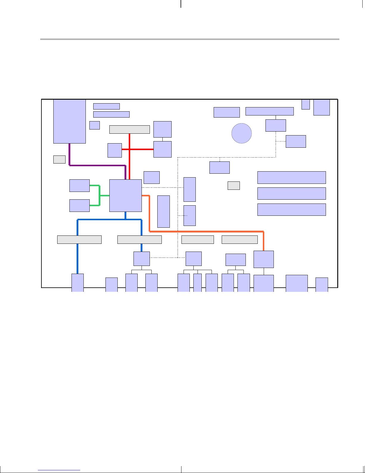
1.2 What’s on the Board?
The EVM comes lo aded with peripherals your mult imedia applications
may need to make use of. T he fol low in g block di agr am show s th e maj or
hardware components.
TI JTAG
SD/
MMC
DC6
Serial Media
DDR
DDR
ARM JTAG
S1
DDR
Video Ports
DC1 (EMIF)
Boot
NAND
EMIF
CPLD
PGM
TMS320
DM357
Storage
NAND
CPLD
S3
What’s on the Board?
IR
MSP430
JTAG
3V
BAT
I2C
I2C
EEPROM
Config
I2C
GPIO
I2C
GPIO
DC7
User LEDs
I2C
GPIO
MSP430
3.3V Boa rd S u pply Voltag e
1.8V I/O Voltage
1.2V CPU Co r e Vo l tage
EMAC
PWR
SW
DC5 (VIDEO OUT)
OUT
COMP
DC4 (VIDEO IN)
SVHS
USB
TVP
5146
IN
IN
VIDEO
DC3 DC2
AIC33
IN
AUDIO
OUT
AUDIO
HP OUT
S/PDIF
Drivers
Optical
S/PDIF
ENET
PHY
10/100
ENET
Analog
S/PDIF
UART
Diagram provided courtesy of Spectrum Digital Inc.
Figure 1–1 DM357 Hardware Block Diagram
For more information about the hardware, see the Spectrum Digital
website at http://support.spectrumdigital.com/boards/evmdm357.
The DaVinci EVM incorporates a battery holder to provide backup power
to the MSP430’s real-ti me clock when the power is no t applied to the
board. The battery is not inclu ded in the kit. See the Spectrum Digital
DaVinci EVM Technical Reference for suggested battery part numbers.
+5V
DVEVM Overview 1-3
Page 12

What’s Next?
1.3 What’s Next?
To get started eval uating the DVEVM kit and d evelo pin g ap pli c ati ons for
the DM357, begin by using this Getting Started guide. It will step you
through connecting the hardware, testing the software, and beginning to
develop applications.
When you are ready for more information about DaVinci Technology and
the DM357 architecture, see the following:
❏ Spectrum Digital website:
http://support.spectrumdigital.com/boards/evmdm357
❏ TI DaVinci Software Updates: http://www.ti.com/dvevmupdates
❏ TI Linux Community for DaVinci Processors:
http://linux.davincidsp.com
❏ Codec Engine Application Developer's Guide (SPRUE67)
❏ TI DaVinci Technology Developers Wiki: http://wiki.davincidsp.com
❏ Other PDF documents on the DVDs included with the DVEVM kit
1-4
Page 13
EVM Hardware Setup
This chapter tells you how to set up the EVM hardware.
Chapter 2
Topic Page
2.1 Setting Up the Hardware . . . . . . . . . . . . . . . . . . . . . . . . . . . . . . . . . . . 2–2
2.2 Connecting to a Console Window . . . . . . . . . . . . . . . . . . . . . . . . . . . 2–6
2-1
Page 14
Setting Up the Hardware
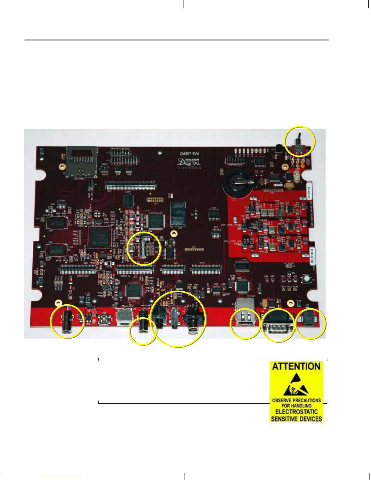
2.1 Settin g U p the Hardware
To set up the hardwa re pr ovided wit h the DVE VM kit, use the steps tha t
follow. You may skip steps if you do not need to access a particular
peripheral. For examp le, if you do not need to use the serial ca ble, skip
that step.
For reference, the num bers in the following photo of the DM357 E VM
target board correspond to the steps in the procedure.
8
8
3
3
1
1
2
2
56 7
56 7
4
4
Important: The EVM board is sensitive to static
discharges. Use a g rounding strap or other de vice to
prevent damaging the board. Be sure to connect
communication cables before applying power to any
equipment.
2-2
Page 15
Setting Up the Hardware
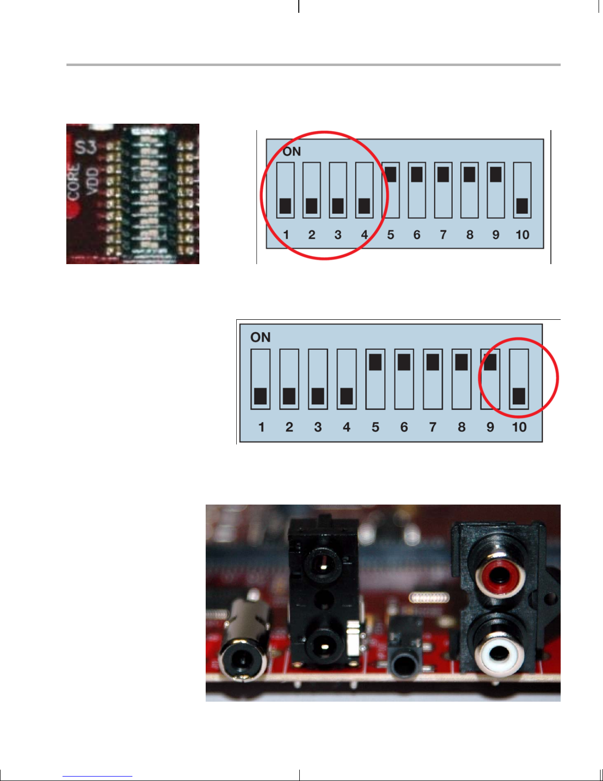
1) On the S3 mini-dip switch, verify that positions 1 through 4 are
configured to boot from on-board NAND as in the following f igure,
where the black rectangle is the switch location.
1
2
3
4
5
6
7
8
9
10
Also on the S3 mini-dip switch, verify that position 10 selects the
correct video format— NTSC or PAL . The following diagram shows
the switch in the NTSC setting.
2) Connect an audio speaker to Stereo Line Out (P5) and an audio
source to Stereo Line In (P3).
Audio In (P3) Audio Out (P5)
EVM Hardware Setup 2-3
Page 16
Setting Up the Hardware
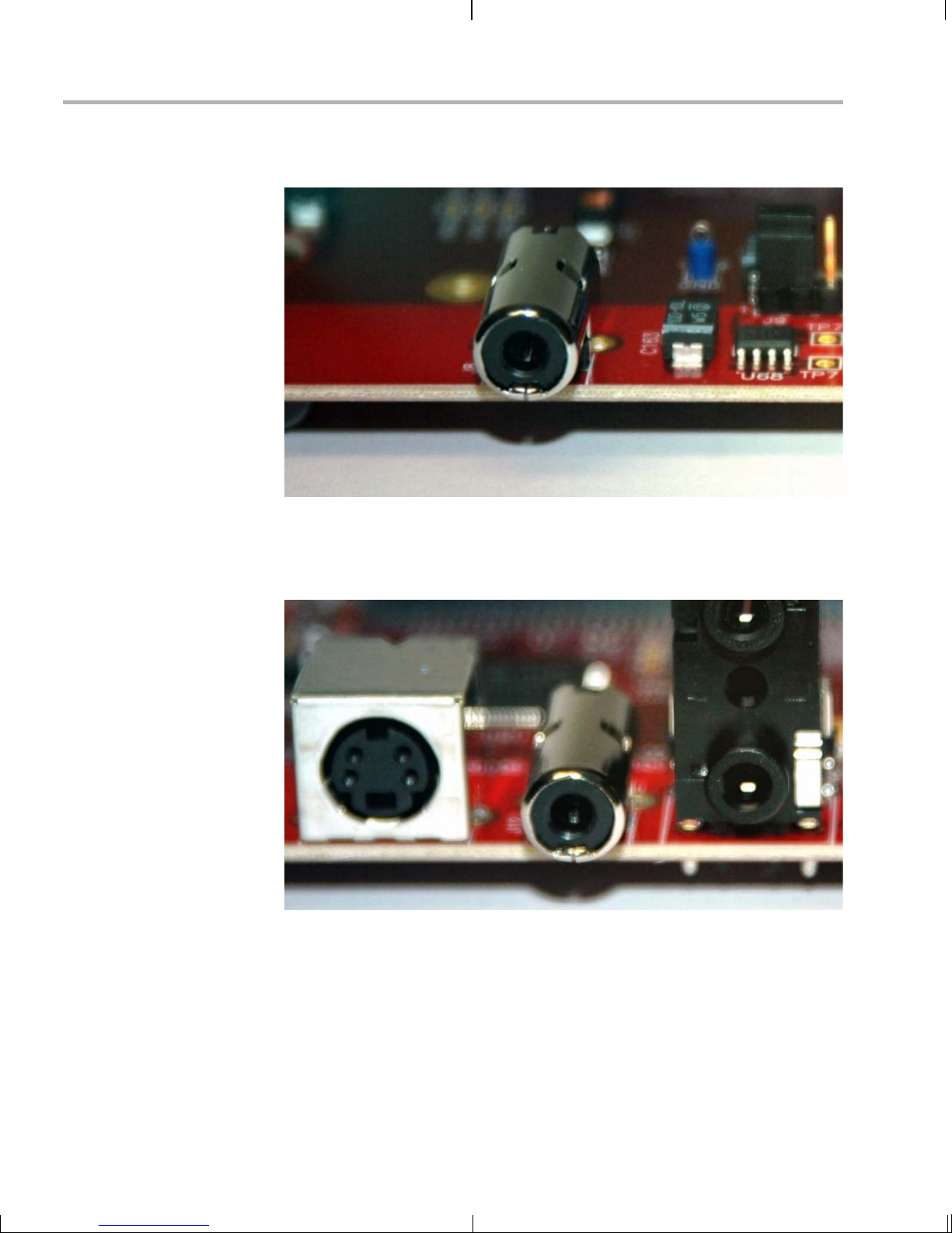
3) Connect your video display to the composite video-out RCA
connector (J8).
Composite
Video Out (J8)
4) Connect a vid eo source (such as a cam era or DVD player) to the
composite video-in RCA connector (J12). Then power on your video
input and output devices.
2-4
Composite
Video In (J12)
Page 17
Setting Up the Hardware
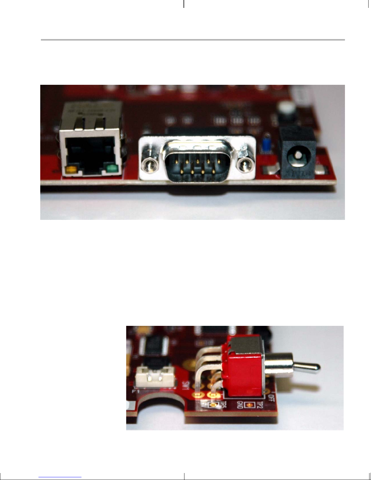
5) (Optional) If you plan to use the UART port for a console window,
connect the pr ovided RS-232 nul l modem cable to the EVM UART
port (P6) and to a COM port on your host Linux workstation.
10/100
Ethernet (P2)
UART (P6) Power (J14)
6) (Optional) If you wil l be using an Ethernet connection, connect the
provided Ethernet c abl e to the E the rnet p or t (P2) on the E V M bo ard
and to an Ethernet network port.
Note: If you do not connect the board’s Ethernet controller to a
computer running a DHCP server, booting the board may take
several additional minutes.
7) Connect the p rovided power cable t o the DVEVM powe r jack (J14)
on the board. T o be ESD safe, plug in the other end of the cable only
after you have connected the power cord to the board.
8) Power on the EVM board by fli pping the powe r swi tch (SW 1).
EVM Hardware Setup 2-5
Page 18

Connecting to a Console Window
9) Y ou should see the initial screen of the demo software on your video
display. Use the IR remote to run the software as described in
Chapter 3.
2.2 Connecting to a Console Window
You can ope n a console window that allows you to watch an d interrupt
EVM boot messages by following these steps:
1) Connect a ser ial cable be tween the seri al port on the EVM and th e
serial port (for example, COM1) on a PC.
2) Run a terminal session (such as Minicom on Linux or HyperTerminal
on Windows) on th e workstation and config ure it to connect to tha t
serial port with the following characteristics:
■ Bits per Second: 115200
■ Data Bits: 8
■ Parity: None
■ Stop Bits: 1
■ Flow Control: No ne
3) When you power on the EVM, you will see boot sequence messages.
You can press a key to interrupt the boot sequence and type
commands in the U-Boot command shell. In this guide, commands to
be typed in the U-Boot shell are indicated by an
EVM # prompt.
2-6
Page 19

Chapter 3
Running the Demonstration Software
This chapter explains how to run the software demos prov ided with the
DVEVM kit.
Topic Page
3.1 Default Boot Configuration. . . . . . . . . . . . . . . . . . . . . . . . . . . . . . . . . 3–2
3.2 Starting the Standalone Demos. . . . . . . . . . . . . . . . . . . . . . . . . . . . . 3–2
3.3 Running the Standalone Demos . . . . . . . . . . . . . . . . . . . . . . . . . . . . 3–5
3.4 Running the Demos from the Command Line . . . . . . . . . . . . . . . . 3–10
3.5 Running the Network Demo . . . . . . . . . . . . . . . . . . . . . . . . . . . . . . . 3–11
3-1
Page 20

Default Boot Configuration
3.1 Default Boot Configuration
Out of the box, the EVM boots from flash and starts the demos
automatically after a few seconds when you power up the board. It does
not require an NFS mount or a TFTP server to run the standard demos.
Note: The default U-Boot bootargs definition sets "ip=off", which disables
the Ethernet connection.
The out-of-the-box boot parameters are listed in Section A.4.1. The
following are alternate ways you may want to boot the board:
❏ TFTP boot with NAND flash file system (Section A.4.2)
❏ Flash boot with NFS file system (Section A.4.3)
❏ TFTP boot with NFS file system (Section A.4.4)
❏ PAL video mode vs. NTSC video mode (Section 2.1)
To abort the sta ndard boot, press any key in th e console window (see
Section 2.2). Also see Section A.4, Alternate Boot Methods if you want to
change the boot configuration.
Note: It is best to power down the board cleanly in order to reboot,
rather than using the reset button or power switch. We recommend
that you use t he shutdown command to s hut down the operating
system and unmo unt the file syste m before removing power from
the board. This will hel p prevent c orruption of the flash-b ased root
file system.
3.2 Starting the Standalone Demos
When you connect the EVM hardware, the pre-loaded examples run
automatically on your video display. These examples encode and
decode audio, video, and speech. There are two ways to use the demos:
❏ Standalone. This is the default power-on mode. The demos run
automatically wi th n o conn ec tio n to a wo r kstation in the defa ult boo t
configuration. This is the mode documented in the rest of this
chapter.
The standalone demo was se t up by the DVSDK, whi ch copies the
file /examples/dvevmdemo to the directory /etc/rc.d/init.d (the central
repository for startup scripts). This file is symbolically linked to
/etc/rc.d/rc3id/S88demo. When the board boots up and enters
runlevel 3, this file is ex ecute d to s tart th e de mo we b s erve r and th e
demo interface.
3-2
Page 21

Starting the Standalone Demos
❏ Command line. Once you have connected the EVM to a workstation
and installed the ne ces sar y so ftware ( as de scr ibe d i n S ecti on 4.3.1 ,
Installing the T arget Linux Software), you can run the demos from the
board’s Linux command line. For furt her information on running the
demos from the command li ne, see the demo doc umentation th at is
linked to by the DVSDK release notes.
Note: When you run the demos fr om the comma nd line, make s ure
the interface process used by the standalone mode demos is not
running. Otherwis e y ou wil l see er ror me ss ag es rais ed whe n d evi c e
drivers fail to open.
Running the Demonstration Software 3-3
Page 22

Starting the Standalone Demos
Once the EVM boar d has boot ed, yo ur vid eo
display should show a picture of the remote
control. You use the IR remote to control the
demos.
The order of the buttons on the actual remote
may be different from the picture; if your
remote looks different, find the buttons with
the same labels on your remote.
To use the demos in standalone mode, follow
these steps:
1) Check to make sure the batteries are
installed in your IR remote.
2) The initial screen shows a diagram of the
IR remote, which you use to run the
standalone demos. Take a minute to look
at the functions of the various buttons.
3) Since this is a universal remote, you may
need to set it to use the codes necessary
to run the DVEVM kit demos. To do this,
hold down the "Code Search" button until
the red light on the remote stays lit. Then
press the "DVD" b utton an d enter "0020 "
as the code.
4) If you accidentally put the remote in TV or
some other mode , press " DVD" to return
the remote to the correct mode.
5) If the remote does not accept the
DVD+0020 code, do a full reset by
removing the batteries, pressing the
Power button for at lea st a minute, then
reinserting the batteries. Then program
the remote as in Step 3.
3-4
Page 23

3.3 Running the Standalone Demos
1) Press "Play" or "OK" on the remote to move from the remote control
diagram to the main menu screen, which looks like this:
Running the Standalone Demos
The Encode + Decode demo allows you to record and playback
video. The Encode demo records audio/speech and video in the
formats you select. The Decode demo plays audio/speech and video
files you select.
2) Use the up and down arrows to change which demo is selected.
Then, press "OK" or "Play" to move to the selected demo.
3) Within a demo, you start at the s ettings screen , where you see th e
controls you can use to run the demo at the bottom of the screen and
the current settings in the upper-right.
4) Use the up and down arrows to move to a setting you want to change.
5) Use the left and right arr ows to cycle through the options until the
setting you want is shown.
6) Press "Play" to begin the Encode+Decode and Decode demos.
Press "Rec" (record) twice to begin the Encode demo.
7) While the d emo runs, data about the settings , processor load, and
rates are shown. Static settings are on the right. Dynamic data
reporting is on the left.
Running the Demonstration Software 3-5
Page 24

Running the Standalone Demos
8) This informati on overl ays the v ideo; as a res ult the v ideo y ou see is
darker than the actual video . To hide the informa tion displ ay so that
you can better see the video, press the "Info/Select" button on the IR
remote. Y ou can change the transparency of the OSD (overlay) while
running a demo by using the left and right arrows on the remote.
9) Press "Stop" or "Pause" when you want to end or pause a demo. The
first time you press "Stop", you return to th e settings screen . Press
"Stop" from the settings screen to go back to the main menu.
For information about runn ing the individual demos, see Section 3.3. 2
through Section 3.3.4.
The demos use the Codec Engine to allow applications to run algorithms.
3.3.1 Shut ting Down the Demos
You can quit out of the demos completely while at the main menu screen
by pressing "Power" on the remote.
Note: It is best to power do wn the boa rd clea nly i n order to reboot
rather than using the reset button or power switch. We recommend
that you use t he shutdown command to s hut down the operating
system and unmo unt the file syste m before removing power from
the board. This will hel p prevent c orruption of the flash-b ased root
file system.
To restart the dem os, you can reboot the boa rd or run the demos fro m
the command line as described in Secti on 3.4.
3-6
Page 25

3.3.2 About the Encode + Decode Demo
The Encode + Decode demo allows you to r ecord and playback video .
Video input comes from a source, it is encoded, then decoded, and sent
to your video display.
The Encode + Dec ode does only video pr ocessing; it does no t encode
and decode audio or s peech. The supported video algorithm is H.264
(.264 file extension).
Table 3–1 IR Remote Buttons for Encode + Decode Demo
IR Remote Button Mode Action Performed
Up/Down -- -- no action -Play or OK Setup Begin demo
Record -- -- no action -Info/Select Setup Show / hide block diagram for demo
Info/Select Run Toggle information display
Left/Right Run Change information transparency level
Running the Standalone Demos
Pause Run Pause demo (press Play to resume)
Stop Setup / Run Return to previous screen
The video signal is passed to video encoders and decoders by the Codec
Engine.
To use this dem o from the c ommand line , see Sectio n 3.4, Run ning the
Demos from the Command Line.
3.3.3 About the Encode Demo
Like the Encode + Decode demo, the Encode demo also encodes video.
In addition, it also encodes audio or speech. The audio/speech source is
the microphone.
The encoded data is written to files on the EVM’s NAND flash. The
possible filenames are demo.264, demo.mpeg4, demo264.g711, and
demompeg4.g711. Older versions of these files are overwritten as
needed.
The encode demo has a fi ve min ute time lim it to preve nt the demo from
filling up the NAND file system.
Output is not de coded and sent to your vid eo disp lay or sp eakers ot her
than to show the settings and dynamic data collected about the load and
rates.
Running the Demonstration Software 3-7
Page 26

Running the Standalone Demos
Note that you can use only a speech encoder, not an audio encoder. The
supported video algorithms are H.264 (.264 extension) and MPEG4
(.mpeg4 file extension). The supported speech algorithm is G.711 (.g711
extension).
Table 3–2 IR Remote Buttons for Encode Demo
IR Remote Button Mode Action Performed
Up/Down Setup Change option selection
Left/Right Setup Change setting of selected option
Play Setup Switch to decode demo
Record (twice)
or OK
Info/Select Setup Show / hide block diagram for demo
Info/Select Run Toggle information display
Left/Right Run Change information transparency level
Pause Run Pause demo (press Record to resume)
Stop Setup / Run Return to previous screen
Setup / Run Begin encode demo, send unencoded
data to display
(There is no display for encode demo
behind the information.)
The application runs on the ARM using Linux. The video and audio
signals are passed to encoders by the Codec Engine.
To use this dem o from the c ommand line , see Sectio n 3.4, Run ning the
Demos from the Command Line.
3-8
Page 27

3.3.4 About the Decode Demo
Note: You must run the Encode demo before you can run the
Decode demo unless yo u have placed appropr iately-named audio
and video files on the EVM’s NAND flash storage device. If you see
a message that says "File Not Found", please run the Encode
demo.
The Decode demo pla ys audio/speech and video f iles you select. Yo u
can select a source video file and a source audio or speech file. Use the
left and right arrow bu ttons to choose from the demo files and the files
created by the Encode demo, which are stored on the EVM’s NAND
flash. The decoded signals are sent to your video display and speakers.
The supported video algorithms are H.264 (.264 extension) and MPEG4
(.mpeg4 file extension). The supported speech algorithm is G.711 (.g711
file extension).
Table 3–3 IR Remote Buttons for Decode Demo
Running the Standalone Demos
IR Remote Button Mode Action Performed
Up/Down -- -- no action -Left/Right Setup Select a different file combination
Play or OK Setup Begin decode demo
Record -- -- no action -Info/Select Setup Show / hide block diagram for demo
Info/Select Run Toggle information display
Left/Right Run Change information transparency level
Pause Run Pause demo (press Play to resume)
Stop Setup / Run Return to previous screen
The application runs on the ARM using Linux. The video and audio
signals are passed to decoders by the Codec Engine.
To use this dem o from the c ommand line , see Sectio n 3.4, Run ning the
Demos from the Command Line.
Running the Demonstration Software 3-9
Page 28

Running the Demos from the Command Line
3.4 Running the Demos from the Command Line
You can run the demo applications from the Linux shell in a terminal
window connected to the EVM b oard’s serial port. The se are the sam e
demos described in Section 3.2, Starting the Standalone Demos.
Before running demo applications from the command line, the CMEM
and accelerator kernel modules must be loaded. Use "lsm od" to see if
they are loaded. If not, use the following commands to load these
modules:
Target $ cd /opt/dvsdk/dm357
Target $ ./loadmodules.sh
To see the command-line options for the demos, use one of the following
commands with the -h or --help option:
Target $ ./encodedecode -h
Target $ ./encode -h
Target $ ./decode -h
You can also find the list of command-line options in encode.txt,
decode.txt, and enc odedecode.txt in the res pective demo dir ectories of
the DVSDK package on the host.
3-10
Page 29
3.5 Running the Network Demo
As an example of standard TCP/IP networking support, the DVEVM
examples include a small HTTP web server. This web server is started
as part of the Linux startup sequence . It configured to service re quests
from web browsers on the standard TCP/IP port 80.
After the EVM board has booted, connect a P C to the same network to
which the EVM board is conne cted. Enter a URL of the form "http://ipaddress-of-evm" in a web browser (for example, Internet Explorer,
Firefox, or Opera). The IP address of the board is shown in the lower-right
corner of the main menu of the A/V demos.
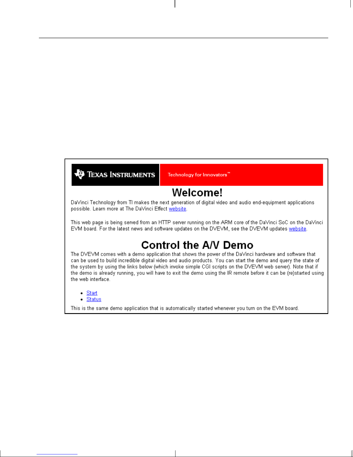
You sho uld see a web page with info rmation about DaVinci technol ogy
and the DVEVM software.
Running the Network Demo
Use this web page to interact with the board and run the A/V demos
described in Section 3.3, Running the Standalone Demos. Two simple
CGI scripts on the EVM enable you to start the demos (assuming they are
not already running) and see what pro cesses are r unning on th e board.
If you want to see the demo started from the web page, be sure to exit
the demo first (use the Power button from the main menu).
The web server software is an open-source package called THTTPD
(http://www.acme.com/software/thttpd/). It is designed to be small, fas t,
and portable. The source code is included with the DVEVM software. You
can get the latest version directly from the web. The web server and CGI
scripts are installed on the target in the /opt/dvsdk/dm357/web directory.
Running the Demonstration Software 3-11
Page 30

3-12
Page 31

Chapter 4
DVEVM Software Setup
This chapter explains how to use the software provided with the DVEVM.
Topic Page
4.1 Software Overview . . . . . . . . . . . . . . . . . . . . . . . . . . . . . . . . . . . . . . . 4–2
4.2 Preparing to Install . . . . . . . . . . . . . . . . . . . . . . . . . . . . . . . . . . . . . . . 4–5
4.3 Installing the Software . . . . . . . . . . . . . . . . . . . . . . . . . . . . . . . . . . . . 4–6
4.4 Setting Up the Build/Development Environment . . . . . . . . . . . . . . 4–12
4.5 Building a New Linux Kernel . . . . . . . . . . . . . . . . . . . . . . . . . . . . . . 4–13
4.6 Rebuilding the DVEVM Software for the Target . . . . . . . . . . . . . . . 4–14
4.7 Building with DSPLink . . . . . . . . . . . . . . . . . . . . . . . . . . . . . . . . . . . 4–15
4.8 Booting the New Linux Kernel . . . . . . . . . . . . . . . . . . . . . . . . . . . . . 4–16
4.9 Using the Digital Video Test Bench (DVTB) . . . . . . . . . . . . . . . . . . 4–17
4-1
Page 32

Software Overview
4.1 Software Overview
To begin developing applications, you need to install the DVEVM
development environment. This section outlines the steps required to
load the DVEVM softwa re onto the deve lopmen t host. You will need the
distribution disks or the files they contain to get started.
The DaVinci software approach provides interoperable, optimized,
production-ready video and audio codecs that leverage integrated
accelerators. These codecs are built into confi gurable framework s, and
are presented via published APIs within popular operating systems (such
as Linux) for rapid software implementation.
The following software is provided with the ARM-side DVEVM software.
❏ Standalone demonstration software. This is provided on the
EVM’s NAND flash. The hard- wired examples encode and decod e
audio, video, and speech. Another demo shows the board’s network
capabilities. See Section 3.2, Starting the Standalone Demos and
Section 3.5, Running the Network Demo.
❏ Disk 1: MontaVista Linux Pro v5.0 System Tools and Target File
System. The version provided with the DVEVM kit is the
demonstration version. It contains the following file:
■ mvl_5_0_demo_sys_setuplinux.bin. This installation file
contains the MontaVista Tool development tool chain and the
target file system.
❏ Disk 2: TI DVSDK Software. This DVD includes demo applications,
Codec Engine software, example codec servers, and DVEVM
documentation. It contains the following files:
■ this manual in PDF format
■ dvsdk_dm357_setuplinux_#_#_#_#.bin (DVSDK installer)
■ mvl_5_0_0_demo_lsp_setuplinux_#_#_#_#.bin
■ xdctools_setuplinux_#_#_#.bin (XDCtools installer)
■ data.tar.gz (Contains A/V data files for use by the demos)
■ restore/dm357_flash_image_#_#_#_#.tar (Contains files for
NAND flash recovery. Contact TI Technical Worldwide Support if
you need details.)
■ restore/overlay.tar.gz (Contains demo files in case they are
needed for recovery. You can ignore this file.)
■ bios_setuplinux_#_#_#.bin (You can ignore this DSP/BIOS
installer because the DM357 EVM contains no DSP.)
❏ Disk 3: SDI Board Support Software. It contains EVM board
utilities.
4-2
Page 33

Texas Instruments, in agreement with MontaVista Software Inc., is
providing a demons tr ation version of the Linux Pr of es si ona l E dit ion v5. 0
embedded operatin g system a nd developm ent tools . The base DVEVM
kit includes a dem onstration version. The demo ver sion is a subset of
what MontaVista provides with the fu ll Professional Edition. Tools such
TM
as DevRocket
and the Professional Edition documentation are not
included, but it is otherwise fully functional and useful for customers
evaluating the DaVinci platform. Also, please note that this release does
not include a MontaVista user lice nse, and no direct custo mer support,
warranty, or indemnification from MontaVista Software Inc. is provided.
You may choose to order the DaVinci Software Production Bundle
(DVSPB), which includes the prod uction release of this demonst ration
version of MontaVista Linux. T his inc ludes a full MontaVista licens e and
the DevRocket IDE.
4.1.1 Command Prompts in This Guide
In this guide, commands are preceded by prompts that indicate the
environment where the command is to be typed. For example:
Software Overview
❏
host $
Indicates command to be typed into the shell window of the host
Linux workstation.
EVM #
❏
Indicates commands to be typed into the U-Boot shell in a console
window connected to the EVM board's serial port. (Section 2.2)
❏
target $
Indicates command s to be typed into th e Linux shell i n the terminal
window connected to the EVM board's serial port.
DVEVM Software Setup 4-3
Page 34

Software Overview
4.1.2 Software Components
The following figure shows the software components used for application
development in the DVEVM kit:
I/O
I/O
I/O
Framework
Components
DMAN3
User Space
Kernel Space
CMEM
Driver
GPIO
Driver
GP
I/O I/O I/O
Timer
USB 2.0
Driver
MMC/SD
Driver
Wtchdg
Timer
Application
VISA API
Codec Engine
VID IMG
SPH AUD
Linux APIsLinux APIs
EMAC
Driver
SPI
Driver
I2C
Driver
Video
Driver
UART
Driver
Engine
Audio
Driver
xDM
API
xDM
API
Video
Codec
Speech
Codec
xDM
API
xDM
API
Imaging
Codec
Audio
Codec
ARM System + MPEG4/H.264/JPEG Co-Processor (HMJCP)
In the previous figure, everything runs on the ARM. The application
handles I/O and application processing. To process video, image,
speech, and audio signals, it uses the VISA APIs provided by the Codec
Engine. The Codec Engine , in turn, uses xDM-bas ed codecs. For mor e
information, see the Codec Engine Application Developer's Guide
(SPRUE67).
In addition, Linux runn ing on the ARM makes a large number of APIs
available to your application, including drivers and timers.
4-4
Page 35

4.2 Preparing to Install
On a host system, mount the DVE VM demo nstratio n DVD and co py the
following files to a temporary location with at least 1.2 GB available
space. Since you can delete the installation files after installing the
software, a directory like /tmp is recommended.
❏ mvl_5_0_demo_sys_setuplinux.bin (disk 1)
❏ mvl_5_0_0_demo_lsp_setuplinux_#_#_#_#.bin (disk 2)
❏ dvsdk_dm357_setuplinux_#_#_#_#.bin (disk 2)
❏ xdctools_setuplinux_#_#_#.bin (disk 2)
Updates to these installer s may be av ail ab le o n the TI DaVinci S oftware
Updates website listed in Section 1.3.
Ensure that an X g ra phic al d is pla y i s a va ilabl e, an d po int y ou r DI SP LAY
environment variable to this value. For example:
csh:
Preparing to Install
host $ setenv DISPLAY cnabc0314159d1:0
ksh or bash:
host $ export DISPLAY=cnabc0314159d1:0
DVEVM Software Setup 4-5
Page 36

Installing the Software
4.3 Installing the Software
Installing the software used by the DVEVM involves performing the
following steps:
❏ Section 4.3.1, Installing the Target Linux Software
❏ Section 4.3.2, Installing the DVSDK Software
❏ Section 4.3.3, Installing the A/V Demo Files
❏ Section 4.3.4, Exporting a Shared File System for Target Access
❏ Section 4.3.5, Testing the Shared File System
4.3.1 I nstalling the Target Linux Software
This section explains how to install Linux for use on the target board. This
is a demonstration version of MontaVista Linux Pro v5.0.
Note that separate versions of Linux are used by the target and your host
Linux workstation. The fol lowing Linux host operating system i s tested
with the DVEVM:
❏ Red Hat Enterprise Linux v4 (Server Edition)
To install the Linux software, follow these steps:
1) Log in as
root on your host Linux work station. Thi s wil l allow you t o
successfully run the graphical installer to install MontaVista Linux.
2) Execute each of the following bin files (where
#_#_#_# is the current
version number) from the temporary location that they were copied in
order to extract the installers for the Linux tools, Linux kernel, and the
file system. If a bin file does not run, make sure these files are
executable (use
chmod +x *.bin).
Instead of the default installation directory, we suggest that you
change the installation folder to /opt/mv_pro_5.0 directory.
host $ ./mvl_5_0_demo_sys_setuplinux.bin
host $ ./mvl_5_0_0_demo_lsp_setuplinux_#_#_#_#.bin
3) After you execu te these .bin files, make sure the following files are
located in /opt/mv_pro_5.0 (or in the /mv_pro_5.0 subdirectory of the
directory you chose in place of the default):
■ mvltools5.0-
#######.tar.gz
■ DaVinciLSP-#_#_#_#.tar.gz
4) Go to the location where you will unpack the tar files. For example:
host $ cd /opt/mv_pro_5.0
4-6
Page 37

5) Unpack the tar files (as root) by using the following commands:
host $ tar zxf mvltools5.0-#######.tar.gz
host $ tar zxf DaVinciLSP-#_#_#_#.tar.gz
This creates the MontaVista directory structure under the
/opt/mv_pro_5.0/mo ntavista/ direc tory.
Note that unpacking these tar files will overwrite any existing files that
were previously installed.
Note: The LSP shippe d with the DVSDK is a multi-platform LSP
and is not configured for a particular platform. As shipped, this LSP
cannot be used to buil d the d emo or exampl e appl icat ions. It m ust
first be copied to a user area and configured/built for the EVM.
Please see Section 4.5 for instructions.
4.3.2 I nstalling the DVSDK Software
Installing the Softwa re
The DVSDK softwa re in cl ude s Code c Engine components, sample data
files, xDAIS and xDM header files, and a contiguous memory allocator for
Linux (CMEM).
To install the DVSDK software using the Linux installer, follow these
steps:
1) Log in using a
user account. The user acc ount must have execute
permission for the dvsdk_dm357_setuplinux_#_#_#_#.bin and
xdctools_setuplinux_#_#_#.bin files.
2) Execute the DVSDK installer that you previously copied from the
DVSDK DVD. For example:
host $ cd /tmp
host $ ./dvsdk_dm357_setuplinux_#_#_#_#.bin
This installs the DVSDK in /home/<useracct>/dvsdk_#_#.
3) Execute the XDC installer that you previously copied from the
DVSDK DVD. For example:
host $ cd /tmp
host $ ./xdctools_setuplinux_#_#_#.bin
When you are prompted, do not us e th e de faul t i ns tallation lo ca tion .
Instead, install the softwar e in the directory crea ted in Step 2. For
example, /home/<useracct>/dvsdk_#_#.
4) You can now delete the .bin fi les that you load ed into th e tempo rary
directory.
DVEVM Software Setup 4-7
Page 38

Installing the Software
Note: You can uninstall these components by using the rm -rf
command on its directory. You should ignore the uninstall files
created by the installer.
4.3.3 I nstalling the A/V Demo Files
The fourth disk contains the A/V files used by the demos. After following
the instructions in the previous section, follow these instructions to install
the A/V files:
1) Go to the demos dir ectory in the DVSDK directory th at you set up
previously. For example:
host $ cd /home/<useracct>/dvsdk_#_#/dvsdk_demos_#_#_#
2) Mount disk 2 and c opy the data.tar.gz file to your DVSDK directo ry.
For example:
host $ cp /mnt/cdrom/data.tar.gz .
3) Extract the A/V data files. For example:
host $ tar zxf data.tar.gz
4.3.4 Exporting a Shared File System for Target Access
Although the board’s NAND flash contains a file system, during
development it i s more co nvenient to have the target board N FS moun t
a file system on a host Linux workstation. Once you have tested the
application, you can store it on the board’s flash for a standalone
demonstration.
Before the board can mount a target file system, you must export that
target file system on the host Linux workstation. The file system uses an
NFS (Network File Sys tem) ser v er. The exported file s yste m wi ll co ntain
the target file system and your executables.
To export the file system from your NFS server, perform the following
steps. You only need to perform these steps once.
1) Log in with a
2) Perform the following commands to prepare a location for the
MontaVista file system. For example:
user account on the host Linux workstation.
host $ cd /home/<useracct>
host $ mkdir -p workdir/filesys
host $ cd workdir/filesys
4-8
Page 39

Installing the Softwa re
3) Switch user to "root" on the host Linux workstation.
host $ su root
4) Perform the fol lowing commands to crea te a copy of the target file
system with permissions set for writing to the shared area as
<useracct>. Substitute your user name for <useracct>. If you
installed in a loc ation oth er than / opt/mv_pr o_5.0, us e your lo catio n
in the cp command.
host $ cp -a /opt/mv_pro_5.0/montavista/pro/devkit/arm/v5t_le/target/* .
host $ chown -R <useracct> opt
5) Edit the /etc/exports file on the host Linux workstation (not the
exports file on the target filesystem). Add the following line for
exporting the filesys area, substituting your user name for
<useracct>. Use the full path from root; ~ may not work for exports
on all file systems.
/home/<useracct>/workdir/filesys *(rw,no_root_squash,no_all_squash,sync)
Note: Make sure you d o no t ad d a s pace betw een the * a nd th e ( in
the above command.
6) Still as root, use th e following commands to make the NFS se rver
aware of the change to its configuration and to invoke an NFS restart.
host $ /usr/sbin/exportfs -av
host $ /sbin/service nfs restart
Note: Use exportfs -rav to re-export all directories. Use
/etc/init.d/nfs status to verify that the NFS status is running.
7) Verify that the server firewall is turned off:
host $ /etc/init.d/iptables status
If the firewall is running, disable it:
host $ /etc/init.d/iptables stop
DVEVM Software Setup 4-9
Page 40

Installing the Software
4.3.5 Testing the Shared File System
To test your NFS setup, follow these steps:
1) Get the IP addre ss of your host L inux workstatio ns as foll ows. L ook
for the IP address associated with the eth0 Ethernet port.
host $ /sbin/ifconfig
2) Open a termi nal e mulati on win dow to connect to the E VM bo ar d vi a
RS-232 using the instructions in Section 2.2. If you have a Windows
workstation, you can use HyperTerminal. If you have a Linux
workstation, you might u se Minicom. (You may need to turn on line
wrap.)
3) Power on the EVM board, and abort the automatic boot sequence by
pressing a key in the console window (Section 2.2).
4) Set the following environment variables in the console window:
EVM # setenv nfshost <ip address of nfs host>
EVM # setenv rootpath <directory to mount>
EVM # setenv bootargs console=ttyS0,115200n8 noinitrd rw
ip=dhcp root=/dev/nfs
nfsroot=$(nfshost):$(rootpath),nolock mem=232M
video=davincifb:vid0=0,2025K:vid1=0,
1350K:osd0=720x576x16,
2025K davinci_enc_mgr.ch0_output=COMPOSITE
davinci_enc_mgr.ch0_mode=ntsc
Note that the setenv bootargs command should be typed on a
single line. Also note that you should avoid using the numeric keypad
to enter numbers, as it can sometimes insert extra invisible
characters.
The
<directory to mount> must match what you specified in Step
5 of Section 4.3.4. For example, /home/<useracct>/workdir/filesys.
Hints: You may want to us e the printenv comm and to print a list of
your environment variables. You can also save these setenv
commands in a .txt file from which you can paste them in the future.
5) Save the environment so that you don't have to retype these
commands every time you cycle power on the EVM board:
EVM # saveenv
6) Boot the board using NFS:
EVM # boot
7) You can now log in as "root" with no password required.
See Section A. 4, Alternate Boot Methods for information about boo ting
with TFTP, NFS, or the board’s NAND flash.
4-10
Page 41

4.3.6 Notes on Using Evaluation/Production Codecs
As part of the DM357 DVSDK installation, you received a number of
codecs:
❏ Sequential JPEG Deco der
❏ Sequential JPEG Enc ode r
❏ MPEG4 Restricted Simple Pr ofile Dec ode r
❏ MPEG4 Simple Profile Encoder
❏ H.264 Base Profile Decoder
❏ H.264 Base Profile Encoder
❏ G.711 Decoder (not a TI codec)
❏ G.711 Encoder (not a TI codec)
These codecs are provided under a "for demonstration-only" license
agreement. If you wish to use these codecs in a production development
environment, you can go to the DVEVM Updates web site at
http://www.ti.com/dvevmupdates to download the latest production
versions, along with the appropriate license agreement.
Installing the Softwa re
DVEVM Software Setup 4-11
Page 42

Setting U p the Build/Development Environment
4.4 Setting Up the Build/Development Environment
To set up the development and build environment, follow these steps:
1) Log in to your
user account (and not as root) on the NFS host
system.
2) Set your PA TH so that the MontaVista tool chain host tools and cross
compiler (arm_v 5t_le-gcc) can be found. For exam ple, in a default
installation of the MontaVista LSP, you should add a definition like
the following to your shell resource file (for example, ~/.bashrc):
PATH="/opt/mv_pro_5.0/montavista/pro/devkit/arm/v5t_le/bin:
/opt/mv_pro_5.0/montavista/pro/bin:
/opt/mv_pro_5.0/montavista/common/bin:$PATH"
If you installed in a location other than /opt/mv_pro_5.0, use your
own location in the P ATH.
3) Remember to use the following command after modifying your
.bashrc file:
host $ source ~/.bashrc
4.4.1 Writing a Simple Program and Running it on the EVM
Make sure you have per formed the steps in Section 4.3.4, Exporting a
Shared File System for Target Access and Section 4.4, Settin g Up the
Build/Development Environment.
Perform the following steps on the NFS host system as user (not as root):
host $ mkdir /home/<useracct>/workdir/filesys/opt/hello
1)
2) host $ cd /home/<useracct>/workdir/filesys/opt/hello
3) Create a file called hello.c with the following contents:
#include <stdio.h>
int main() {
printf("Buongiorno DaVinci!\n");
return 0;
}
4) host $ arm_v5t_le-gcc hello.c -o hello
Perform the followi ng st eps on the target bo ard. You may use either the
target's console window (Section 2.2) or a telnet session.
target $ cd /opt/hello
1)
2) Run ./hello. The output should be:
Buongiorno DaVinci!
4-12
Page 43

4.5 Building a New Linux Kernel
If you modify the target’s Linux kernel sources, you will need to rebuild it
and then boot it up by either replacing the kernel that comes installed on
the EVM board’s flash or by having the U-Boot utility use T FTP to boot
the kernel over a network connection.
Make sure you have completed Section 4.4, Setting Up the
Build/Development Environment and Section 4.4.1, Writing a Simple
Program and Runnin g it on the EVM before attempting to build a new
kernel.
To rebuild the Linux Kernel, follow these steps:
1) Log in to your user account (not as root).
Building a New Linux Kernel
2) Set the
PLATFORM variable in the Rules.make file as described in
Section 4.6.
3) Use commands like the following to make a local working copy of the
MontaVista Linux Support Package (LSP) in your home directory.
This copy contains the embedded Linux 2.6.18 kernel plus the
DaVinci drivers. If you installed in a location other than
/opt/mv_pro_5.0, use your location in the cp command.
host $ cd /home/<useracct>
host $ mkdir -p workdir/lsp
host $ cd workdir/lsp
host $ cp -R /opt/mv_pro_5.0/montavista/pro/devkit/lsp/ti-davinci .
4) Use the following commands to configure the kernel using the
DaVinci defaults. Note that CROSS_COMP ILE sp ecifi es a prefix for
the executables that is used during compilation:
host $ cd ti-davinci/linux-2.6.18_pro500
host $ make ARCH=arm CROSS_COMPILE=arm_v5t_le- davinci_dm357_defconfig
5) To modify the kernel options, you will need to use a configuration
command such as " mak e m enu co nfi g" o r " ma ke xconfig". To en abl e
the MontaVista default kernel options, use the following command:
host $ make ARCH=arm CROSS_COMPILE=arm_v5t_le- checksetconfig
host $ make ARCH=arm CROSS_COMPILE=arm_v5t_le- uImage
6) Compile the kernel using the following command:
DVEVM Software Setup 4-13
Page 44

Rebuilding the DVEVM Software for the Target
7) If the kernel is configured with any loadable modules (that is,
selecting <M> for a module in menuconfig), use the following
commands to rebuild and install these modules:
host $ make ARCH=arm CROSS_COMPILE=arm_v5t_le- modules
host $ make ARCH=arm CROSS_COMPILE=arm_v5t_le-
INSTALL_MOD_PATH=/home/<useracct>/workdir/filesys modules_install
8) Use the following command to copy uImage to a place where U-Boot
can use TFTP to download it to the EVM. These commands assume
you are using the default TFTP boot area, which is /tftpboot. If you
use another TFTP root location, please change /tftpboot to your own
TFTP root location. (Perform these commands as root or use a
uImage
host $ cp /home/<useracct>/workdir/lsp/ti-davinci/linux_2.6.18_pro500/arch/arm/boot/uImage /tftpboot
host $ chmod a+r /tftpboot/uImage
command to get ownership of the file.)
chown
For more information on setting up a TFTP server, see Section A.3.
See a standard Linux ker nel reference book or onlin e source for more
about Linux build configurati on opti on s.
4.6 Rebuilding the DV EVM Software for the Target
To place demo files in the /opt/dvevm d irectory, you need to rebuild th e
DVEVM software. To do this, follow these steps:
1) If you have not already done so, rebuild the Linux kernel as described
in Section 4.5.
2) Change directory to dvsdk_#_#.
3) Edit the dvsdk_#_#/Rules.make file.
■ Set PLATFORM to match your EVM board as follows:
PLATFORM=dm357
■ Set DVSDK_INSTALL_DIR to the top-lev el DVEVM installation
directory as follows:
DVSDK_INSTALL_DIR=/home/<useracct>/dvsdk_#_#
■ Make sure EXEC_DIR points to the opt directory on the NFS
exported file system as follows:
EXEC_DIR=/home/<useracct>/workdir/filesys/opt/dvsdk/dm357
■ Make sure MVTOOL_DIR points to the MontaVista Linux tools
directory as follows:
MVTOOL_DIR=/opt/mv_pro_
4-14
5.0
/montavista/pro/devkit/arm/
v5t_le
Page 45

Building with DSPLink
■ Make sure LINUXKERNEL_INSTALL_DIR is defined as follows:
LINUXKERNEL_INSTALL_DIR=/home/<useracct>/workdir/lsp/ti-davinci/linux-2.6.18_pro500
■ Modify the following envi ronment variable as needed to match
the location of XDCtools on your Linux host. We recommend that
XDCtools be installed in the /home/<useracct>/dvsdk_#_#
directory, but you may have installed it elsewhere.
XDC_INSTALL_DIR=/home
4) While in the same directory that contains Rules.make, use the
following command s to b uil d t he DV S DK d emo ap pli c ati ons and put
the resulting binaries on the target file system specified by
EXEC_DIR.
host $ make clean
host $ make
host $ make install
5) You can test the rebuilt DVEVM software by booting yo ur NFS file
system and running the demos from the command line as described
in Section 3.4.
4.7 Building with DSPLink
The DSPLink build system now re quire s a GNU ma ke ve rsi on of 3.81 or
greater. Currently, v ersions of GNU mak e that qua lify a re vers ions 3.81 ,
3.81beta1, 3.90, and 3.92. Red Hat Linux 3 and 4 usually have GNU
make 3.80 pre-installed, which will not build DSPLink.
To work arou nd this, either i nstall and build a version of make 3.81+ or
use the make 3.81beta1 distributed with XDCtools. The 3.81beta1
version of make is located in XDC_TOOLS_DIR/gmake.
/<useracct>/dvsdk_#_#/xdctools_#_#
See the DSPLink documentation for further information about building.
DVEVM Software Setup 4-15
Page 46

Booting the New Linux Kernel
4.8 Booting the New Linux Kernel
After building the new kernel, in order to use it to boot the DaVinci board,
you must transfer it to the board via TFTP. It is assumed you have
completed the steps in Section 4.5, Building a New Linux Kernel and the
boot file, uImage has been copied to /tftpboot (or some other site-specific
TFTP accessible location).
1) Power on the EVM board, and abort the automatic boot sequence by
pressing a key in the console window (Section 2.2).
2) Set the following environment variables. (This assumes you are
starting from a def ault, clean U-Boot env ironment. S ee Secti on 3.1,
Default Boot Configuration for information on the U-Boot default
environment.)
EVM # setenv bootcmd 'dhcp;bootm'
EVM # setenv serverip <tftp server ip address>
EVM # setenv bootfile uImage
EVM # setenv bootargs mem=232M console=ttyS0,115200n8
root=/dev/mtdblock0 rw rootfstype=yaffs2 ip=dhcp
video=davincifb:vid0=0,2025K:vid1=0,
1350K:osd0=720x576x16,
2025K davinci_enc_mgr.ch0_output=COMPOSITE
davinci_enc_mgr.ch0_mode=ntsc
EVM # saveenv
Note that the setenv bootargs command should be typed on a
single line.
3) Boot the board:
EVM # boot
This configuration boot s a new Linux kernel via TFTP with a NAND flash
based file system. To boot using an NFS file system, see Section A.4.4.
For instructions on how to ver ify that your host workstatio n is running a
TFTP server, and for instructions on what to do if it isn’t, see Section A.3.
For more details on booting, see Section A.4.
4-16
Page 47

Using the Digital Video Test Bench (DVTB)
4.9 Using the Digital Video Test Bench (DVTB)
The Digital Video T est Bench (DVTB) is a Linux utility that was developed
to execute end-to-end data flows using the DVSDK for any platform.
DVTB uses the Codec Engine VISA APIs and Linux driver peripheral
APIs to encode and decode video, image, audio and speech streams.
Using DVTB, you can configure codecs and/or peripherals before starting
a data flow. This enables you to try different use case scenarios and
evaluate the system.
The DVSDK installation places DVTB in the
/home/<useracct>/ dvsdk_ #_#/dvtb_# _#_# directo ry, where #_#_# is the
DVTB version number.
To install DVTB to the target fi le system, perform the following ste ps on
the host machine where the DVSDK has been installed:
1) Make sure the Rules.make file defines PLATFORM correctly as
described in Section 4.6.
2) Perform the following commands:
host $ cd /home/<useracct>/dvsdk_#_#/dvtb_#_#_#
host $ make clean CONFIGPKG=dm357
host $ make CONFIGPKG=dm357
3) Copy the binari es "dvtb-d" and "dvtb-r " to /opt/dvsdk/dm357 on the
device’s target filesystem and run it there. It must be in the same
directory as the DSP executables.
For further details on the DVTB, see the following documents:
❏
Release Notes.
/home/<useracct>/dvsdk_#_#/dvtb_#_#_#/docs/dvtb_release_notes.pdf
❏ User Guide..
/home/<useracct>/dvsdk_#_#/dvtb_#_#_#/docs/dvtb_user_guide.pdf
DVEVM Software Setup 4-17
Page 48

4-18
Page 49

Appendix A
Additional Procedures
This appendix describes optional procedures you may use depending on
your setup and specific needs.
Topic Page
A.1 Changing the Video Input/Output Methods. . . . . . . . . . . . . . . . . . . . A–2
A.2 Putting Demo Applications in the Third-Party Menu . . . . . . . . . . . . A–3
A.3 Setting Up a TFTP Server . . . . . . . . . . . . . . . . . . . . . . . . . . . . . . . . . . A–5
A.4 Alternate Boot Methods . . . . . . . . . . . . . . . . . . . . . . . . . . . . . . . . . . . A–6
A.5 Updating/Restoring the Bootloaders. . . . . . . . . . . . . . . . . . . . . . . . . A–9
A.6 Restoring the NAND Flash . . . . . . . . . . . . . . . . . . . . . . . . . . . . . . . . A–12
A-1
Page 50

Changing the Video Input/Output Methods
A.1 Changing the Video Input/Output Methods
U-Boot reads the S3 mini-di p swi tch, posit ion 10 setti ng on boot- up an d
stores the results in th e videostd env ironment var iable. As lon g as your
U-Boot bootcmd sets the video output using the videostd variable (as the
example bootcmds in Se ction A .4, Alte rnate Boot M ethods d o), yo u ca n
switch between NTSC and PAL by simply changing the S3 switch setting
as shown in Section 2.1, Setting Up the Hardware.
To automatically update the bootargs based on the S3 switch setting,
please use the following options:
EVM # setenv bootargs 'mem=232M console=ttyS0,115200n8
root=/dev/mtdblock0 rw rootfstype=yaffs2 ip=dhcp
video=davincifb:vid0=0,2025K:vid1=0,
1350K:osd0=720x576x16,
2025K davinci_enc_mgr.ch0_output=COMPOSITE
EVM # setenv bootcmd 'setenv setboot setenv bootargs
\$(bootargs) davinci_enc_mngr.ch0_mode=\$(videostd);run
setboot;nboot 0x80700000 0 0x400000;bootm'
If you do not want to use the video std variabl e in your bo otcmd, use th e
following options within your bootargs setting. The difference between
the NTSC and PAL settings is shown in bold.
NTSC
video=davincifb:vid0=0,2025K:vid1=0,
1350K:osd0=720x576x16,
2025K davinci_enc_mgr.ch0_output=COMPOSITE
davinci_enc_mgr.ch0_mode=ntsc
PAL
video=davincifb:vid0=0,2025K:vid1=0,
1350K:osd0=720x576x16,
2025K davinci_enc_mgr.ch0_output=COMPOSITE
davinci_enc_mgr.ch0_mode=pal
A-2
Page 51

Putting Demo Applications in the Thi rd-Party Menu
A.2 Putting Demo Applications in the Third-Party Menu
You ca n add your own d emos to the Thir d-Party Menu by following the
steps in this section. Only four demos can be shown at once in the userinterface. If you add more than four demos, the first four in alphab etical
order are shown.
1) Create the following files for your demo:
logo.jpg. This is the logo of the third party company which will be
■
showed next to the demo description. The picture needs to be in
JPEG format and of size 50x50.
readme.txt. This i s a text fil e. The first 40 characters of t he file
■
should briefly d escribe the demo. The demo interface displays
up to 40 characters, but stops if it encounters a new line
character. For example, the file might contain "Video Phone
demo" or "Network Audio demo".
app.sh. This is an ex ecutable that launches yo ur demo. It can
■
either be the demo executable itself or a shell script that
executes the executable. (If this is a shell script, make sure its
executable bit is set for all). A script could look something like:
#!/bin/sh
exec ./mydemoname
■ other files. If app.sh is a shel l sc r ipt, y our dem o e xe cutable wi ll
have some othe r nam e. You may also need to inc l ude data fil es
or other files used by the executable.
Note: The demo applicati on mu st use re lat iv e paths to ac ce ss any
files it needs at runtime. This because the archive is extra cted to
another location from which the demo is executed.
2) Create a gzipped tar file (ends with .tar.gz) that archives all the files
in the previous list. For example, if your files are logo.jpg, readme.txt,
and app.sh, you could use the following command:
tar cvzf ti_videophone.tar.gz logo.jpg readme.txt app.sh
Name the tar file using <company>_<demoname>.tar.gz (with no
spaces in the file name) as the convention. For example, a video
phone demo created by Texas Instruments would be named
ti_videophone.tar.gz. The name must be unique since all demos ar e
installed in the same directory.
The three required files must be in the top-level directory of the
archive. Other file s may be in subdirectories , so long as the demo
Additional Procedures A-3
Page 52

Putting Demo Applications in the Third-Party Menu
uses relative referen ces to acc ess them. For examp le, the follo wing
directory structure might be used in the archive:
|-- app.sh
|-- data
| |-- datafile1
| `-- datafile2
|-- logo.jpg
`-- readme.txt
To check the format of the file you create, execute the following
command in Linux. The result should say "gzip compressed data".
file <filename>.tar.gz
3) Put your archi ve in the "thirdpartydemos " subdirectory of the targe t
installation directory. This is where the DVEVM software was
installed on the target file system. The default target installation
directory is /opt/dv evm, so th e default locat ion for demo a rchives is
/opt/dvevm/thirdpartydemos. Do not extract the contents of the
archive in this l ocation. Extraction is performed beh ind-the-scenes
each time the demo is run.
A-4
Page 53

A.3 Setting Up a TFTP Server
You can check to see if a TFTP server is set up with the following
command:
host $ rpm -q tftp-server
If it is not set up, you can follow these steps:
1) If you have not yet installed MontaVista Linux Demo Edition (see
Section 4.3.1), you ca n down load a T FTP serv er for you r Linux host
from many locations on the Internet. Search for "tftp-server".
Setting Up a TFTP Server
2) To install TFTP, use this command, where
-#.#-# is the version
number portion of the filename:
host $ rpm -ivh tftp-server-#.#-#.rpm
You should see the following output:
warning: tftp-server-#.#-#.rpm:
V3 DSA signature: NOKEY, key ID 4f2a6fd2
Preparing... #################################### [100%]
1:tftp-server ################################### [100%]
3) Confirm that TFTP is installed with this command:
host $ /sbin/chkconfig --list | grep tftp
If you want to turn on the TFTP server, use this command:
/sbin/chkconfig tftp on
The default root location for servicing TFTP files is /tftpboot.
Additional Procedures A-5
Page 54

Alternate Boot Methods
A.4 Alternate Boot Methods
The default conf iguration for the E VM is to boot from flash with the file
system on the board’s NAND flash. The following are alternate ways you
may want to boot the board:
❏ TFTP boot with NAND flash file system (Section A.4.2)
❏ Flash boot with NFS file system (Section A.4.3)
❏ TFTP boot with NFS file system (Section A.4.4)
The subsections that follow show the environment variable settings used
to enable each boot method.
To boot in one of these modes, follow these steps:
1) Power on the EVM board, and abort the automatic boot sequence by
pressing a key in the console window (Section 2.2).
Set the environment v ar iab le s indi ca ted in the following subsec ti ons
for the boot mode you want to use. (Note that the
command should be typed on a single line.)
setenv bootargs
2) If you want to use these settings as the default in the future, save the
environment:
EVM # saveenv
3) Boot the board using the settings you have made:
EVM # boot
A.4.1 Booting from Flash Using Board’s NAND Flash File System
This is the default, out-of-the-bo x boot confi gurati on .
To boot in this mode, set the following parameters after you abort the
automatic boot sequence:
EVM # setenv bootcmd 'nboot 0x80700000 0 0x400000;bootm'
EVM # setenv bootargs console=ttyS0,115200n8 ip=dhcp
root=/dev/mtdblock0 rw rootfstype=yaffs2 mem=232M
video=davincifb:vid0=0,2025K:vid1=0,
1350K:osd0=720x576x16,
2025K davinci_enc_mgr.ch0_output=COMPOSITE
davinci_enc_mgr.ch0_mode=ntsc
EVM # boot
When you boot, look for the following line that confirms the boot mode:
## Booting image at 80700000 ...
A-6
Page 55

A.4.2 Booting via TFTP Using Board’s NAND Flash File System
To boot in this mode, set the following parameters after you abort the
automatic boot sequence:
EVM # setenv bootcmd 'dhcp;bootm'
EVM # setenv bootargs console=ttyS0,115200n8 ip=dhcp
root=/dev/mtdblock0 rw rootfstype=yaffs2 mem=232M
video=davincifb:vid0=0,2025K:vid1=0,
1350K:osd0=720x576x16,
2025K davinci_enc_mgr.ch0_output=COMPOSITE
davinci_enc_mgr.ch0_mode=ntsc
EVM # setenv serverip <tftp server ip address>
EVM # setenv bootfile <kernel image>
EVM # boot
When you boot, look for the following lines that confirm the boot mode:
TFTP from server 192.168.160.71; our IP address is
192.168.161.186
Filename 'library/davinci/0.4.2/uImage'.
...
## Booting image at 80700000 ...
Alternate Boot Methods
A.4.3 Booting from Flash Using NFS File System
To boot in this mode, set the following parameters after you abort the
automatic boot sequence:
EVM # setenv bootcmd 'nboot 0x80700000 0 0x400000;bootm'
EVM # setenv nfshost <ip addr of nfs host>
EVM # setenv rootpath <directory to mount*>
EVM # setenv bootargs console=ttyS0,115200n8 noinitrd rw
ip=dhcp root=/dev/nfs nfsroot=$(nfshost):$(rootpath),
nolock mem=232M
video=davincifb:vid0=0,2025K:vid1=0,
1350K:osd0=720x576x16,
2025K davinci_enc_mgr.ch0_output=COMPOSITE
davinci_enc_mgr.ch0_mode=ntsc
EVM # boot
*For example, <directory to mount> might be
/home/<useracct>/workdir/filesys.
Additional Procedures A-7
Page 56

Alternate Boot Methods
When you boot, look for the following lines that confirm the boot mode:
## Booting image at 80700000 ...
...
Starting kernel ...
...
VFS: Mounted root (nfs filesystem).
A.4.4 Booting via TFTP Using NFS File System
To boot in this mode, set the following parameters after you abort the
automatic boot sequence:
EVM # setenv bootcmd 'dhcp;bootm'
EVM # setenv serverip <ip addr of tftp server>
EVM # setenv bootfile <name of kernel image>
EVM # setenv rootpath <root directory to mount>
EVM # setenv nfshost <ip addr of nfs host>
EVM # setenv bootargs console=ttyS0,115200n8 noinitrd rw
ip=dhcp root=/dev/nfs nfsroot=$(nfshost):$(rootpath),nolock
mem=232M video=davincifb:vid0=0,2025K:vid1=0,
1350K:osd0=720x576x16,
2025K davinci_enc_mgr.ch0_output=COMPOSITE
davinci_enc_mgr.ch0_mode=ntsc
EVM # boot
The <root directory to mount> must match the filesystem that you set up
on your workstation. For example, /home/<useracct>/workdir/filesys.
When you boot, look for the following lines that confirm the boot mode:
TFTP from server 192.168.160.71; our IP address is
192.168.161.186
Filename 'library/davinci/0.4.2/uImage'.
...
Starting kernel ...
...
VFS: Mounted root (nfs filesystem).
A-8
Page 57

A.5 Updating/Restoring the Bootloaders
The DM357 EVM board contains 2 GB of N AND flash memory. During
the boot process 64 MB of NAND is used. After booting, 2 GB are used
for the file system.
When the EVM board is reset, the ROM bootloader (RBL) executes,
initializing the board and then loading a small program called UBL (User
Bootloader) from NAND flash memory into internal memory for
execution. UBL in turn loads the U-Boot bootloader program from NAND
flash memory. The U-Boot bootloader is responsible for loading and
starting the Linux kernel.
Therefore, there are two bootloader images that need to be stored in the
EVM's NAND flash memory: UBL and U-Boot. This section describes
how to flash UBL and U-Boot in case these images are corrupted or need
to be updated.
If the U-Boot image is i ntact in the EVM flas h memo ry, you can use it to
update itself. If working U-Boot (or UBL) images are not present in flash,
you will need to restore these images using Code Composer Studio
(CCStudio) and an emulator. The subsections that follow explain both of
these procedures.
Updating/Res tori ng the Bootloaders
You can fi nd UBL, U- Bo ot, and the NA ND pr ogram mer pre- bu ilt bina ries
in your DVSDK installation. The location for these is typically the
/home/<useracct>/dvsdk_#_#/PSP_#_#_#_#/bin/dm357 directory.
Alternatively, the source code for the Bootloader components can be
found in the /home/<u se racc t> /dv sdk_ #_# /PS P_ #_# _#_ #/bo ar d_u til ities
directory.
For further information about upg r adi ng and flashi ng, s ee the TI DaVinci
Technology Developers Wiki at http://wiki.davincidsp.com.
A.5.1 Updating U-Boot Using U-Boot
If the U-Boot image is i ntact in the EVM flas h memo ry, you can use it to
update itself by following these steps:
1) After aborting the automatic boot sequence, assign an IP address to
the EVM board using one of these methods:
■ If you are on a standalone network or using a network cross
cable to your workstation , you can assign a static IP address to
the EVM as follows:
EVM # setenv ipaddr <static IP address>
Additional Procedures A-9
Page 58

Updating/Restoring the Bootloaders
EVM # dhcp
EVM # setenv ipaddr <IP address returned by dhcp>
2) Set the TFTP server IP address:
EVM # setenv serverip <TFTP server IP address>
3) Save these settings to the flash memory:
EVM # saveenv
4) Load U-Boot. To load U-Boot, the U- Boot image mu st be copied t o
EVM # tftp 0x80700000 <u-boot file name>
■ To assign a dynamic address, use the following:
the TFTP directory (usually /tftpbo ot), and the tftp command must
specify both the image name and the destination address. In this
case, the destination is in DDR memory starting at address
0x80700000, chosen arbitrarily in the DDR space.
NAND Device
Boot device U6
(SAMSUNG K9F1208R0B-JIB0)
Storage Device U67
(MICRON MT29F16G08FAAWC:A)
5) Erase the U-Boot location at the "U-Boot Load Address" shown in the
previous table for your NAND device with a size that is larger than the
"Bytes transferred" value from Step 4.
EVM # nand erase <U-Boot Load Address> 0x20000
6) Flash the new U-Boot from 0x80700000 to the U-Boot Load Address
shown in the previous table for the corresponding NAND device.
EVM # nand write 80700000 <U-Boot Load Address> 20000
7) Power cycle the board or type "reset" to reboot. Verify that the
recently flashed U-Boot is working by inspecting the build date on the
serial terminal console output.
Total
Size
512 MB 64 MB x 8 0x18000
2 GB not accessible from
Sector
Size
U-Boot Load
Address
U-Boot
A-10
Page 59

Updating/Res tori ng the Bootloaders
A.5.2 Updating UBL and U-Boot Bootloaders Using an Emulator and CCStudio
If working U-Boot (or UBL) images are not present in flash, you will need
to restore these images using Code Composer Studio (CCStudio) and an
emulator. Follow these steps:
1) Find the NAND programmer utilities. The NAND Programmer binary
(NANDWriter.out) is in
/home/<useracct>/dvsdk_#_##/PSP_#_#_#_#/bin/dm357.
Alternatively, the source for the NAND progr ammer utilities can be
extracted from your DVSDK installation at
/home/<useracct>/dvsdk_#_##/PSP_#_#_#_#/board_utilities.
Extract them onto a PC workstation that has CCStudio 3.3 (or higher)
and an XDS560 or XDS510 emulator installed.
2) Configure CCStudio to connect to the DM357 EVM board using
CCStudio Setup and the DM357 GEL files. The .ccs and .gel files are
not included in the PSP package. You can download them from
http://support.spectrumdigital.com/boards/evmdm357.
3) Connect an emulator to the EVM board's JT AG connector and power
up the EVM board.
4) Open CCStudio and connect to the device (Alt+C).
5) Load the program NANDWriter.out and run it (F5).
6) Enter the full UBL path and file name for ubl_DM357_nand.bin in the
dialog box.
7) Enter the full U-Boot path and file name for
u-boot-1.2.0-dm357- na nd.b in in the dialog box.
8) At the next two prompts, enter 0x82080000.
9) Wait until NAND programming is complete.
10) Cycle power on the EVM board and press any key on the EVM's
monitor window to get the U-Boot prompt.
Additional Procedures A-11
Page 60

Restoring the NAND Flash
A.6 Restoring the NAND Flash
You ca n re sto re th e con tents of t he DVS DK NA ND f las h me mory on th e
EVM board via N FS (Section A.6.2) or via R AM Disk and an SD card
(Section A.6.3). These c ontents include the Linux ke rnel and filesyst em
and the demo ap plication software . However, you must first update the
kernel on the NAND flash as described in Section A.6.1.
The DVSDK NAND image is incl uded on the DVSDK (disk #2) restore
directory (or the http:// www.ti.com/dvevmupdate s extran et) and is called
"dm357_flash_image_#_#_#_#.tar", where #_#_#_# is the version.
A.6.1 Updating the Kernel
The Linux kernel (uImage) can be loaded to the NAND flash via TFTP.
This step is required befo re you restore the NAND flash, whe ther you
plan to do that via NFS (Section A .6.2 ) or vi a RAM Dis k and an SD c ard
(Section A.6.3).
To load the kernel, the file name of the kernel image that is in the server's
tftp directory (usually /tftpboot) an d the destination address need to be
specified. Execute the following commands to download the kernel
image and write to the NAND partition.
1) Copy the uImage-dm357 file to /tftpboot/uImage to rename the file as
required by the following steps.
2) Assign an IP address to the EVM board using one of these methods:
■ If you are on a standalone network or using a network cross
cable to your workstation , you can assign a static IP address to
the EVM as follows:
EVM # setenv ipaddr <static IP address>
EVM # setenv serverip <tftp server IP address>
EVM # tftp 0x80700000 uImage
■ To assign a dynamic address, use the following commands:
EVM # setenv bootfile uImage
EVM # setenv serverip <tftp server IP address>
EVM # dhcp
3) Download the kernel image and write to the NAND flash as follows:
EVM # nand erase 0x400000 0x200000
EVM # nand write 0x80700000 0x400000 0x200000
A-12
Page 61

Restoring the NAND Flash
A.6.2 Restoring the NAND Flash Using NFS
Once you have loaded the kernel binary to the corresponding NAND
partition as described in Section A.6.1, you can use NFS to populate the
YAFFS2 image (dm357_flash_image_#_#_#_#.tar) to the NAND
partition. The YAFFS2 image should reside on the NFS Server root
directory. Follow these steps:
1) Copy the dm357_flash_image_#_#_#_#.tar file from the DVSDK disk
to the NFS mounted root directory. For example,
/home/<useracct>/workdir/filesys.
2) Set the bootcmd environment variable to boot to kernel and mount to
NFS. (Alternatively use the 'dhcp' command for the EVM IP
Address.)
EVM # setenv bootcmd 'nboot 0x80700000 0 0x400000; bootm'
EVM # setenv bootargs console=ttyS0,115200n8 noinitrd
ip=dhcp root=/dev/nfs rw nfsroot=<nfs_host_ip>:<nfs_root_path> mem=232M
video=davincifb:vid0=0,2025K:vid1=0,1350K:osd0=720x576x16,
2025K davinci_enc_mgr.ch0_output=COMPOSITE
davinci_enc_mgr.ch0_mode=ntsc
Note: These variables need not be saved, because NFS is just a
temporary filesystem.
3) Execute the 'boot' command to boot the Linux kernel.
4) Login to the EVM as root and execute the following set of U-Boot
commands to mount t he NAND partition and pop ulate the YAFFS2
image:
EVM # mkdir /mnt/nand
EVM # flash_eraseall /dev/mtd0
EVM # mount -t yaffs2 /dev/mtdblock0 /mnt/nand/
EVM # cd /mnt/nand
EVM # tar xf /dm357_flash_image_#_#_#_#.tar
EVM # cd
EVM # umount /mnt/nand
EVM # reboot
5) When the EVM com es up after rebooting from the previous steps,
press Esc to get back to U-Boot prompt. You can now restore the outof-the-box U-Boot environment variables as described in Section
A.4.1.
Additional Procedures A-13
Page 62

Restoring the NAND Flash
A.6.3 Restoring the NAND Flash Using RAM Disk and a 2 GB SD Card
This procedure assumes the TFTP setup in Section A.3 has been
performed.
Once you have loaded the kernel binary to the corresponding NAND
partition as described in Section A.6.1, you can load the Ramdisk image
(ramdisk.gz) to the DDR memory via TFTP. The YAFFS2 image resides
on the 2 GB SD c ard. An MMC/ SD card reader sh ould be use d to copy
the YAFFS2 image on the 2 GB SD card. Follow these steps:
1) Find the RAM disk image at
/home/<useracc t>/ dv sd k_ #_#/ PS P_ #_#/bin and copy it to the host’s
/tftpboot directory.
2) After aborting the boot seq uence, downloa d the RAM dis k image to
the RAM as follows:
EVM # tftp 0x82000000 ramdisk.gz
3) Set the following environment variables to boot to Kernel and mount
to the RAM disk.
EVM # setenv bootcmd 'nboot 0x80700000 0 0x400000; bootm'
EVM # setenv bootargs mem=232M console=ttyS0,115200n8
root=/dev/ram0 rw initrd=0x82000000,4M ip=off
video=davincifb:vid0=0,2025K:vid1=0,
1350K:osd0=720x576x16,
2025K davinci_enc_mgr.ch0_output=COMPOSITE
davinci_enc_mgr.ch0_mode=ntsc
Note: These variables need not be saved to the NAND flash, as the
RAM disk is just a temporary filesystem.
4) Plug the 2GB SD Card into the MMC/SD slot on the DM357 EVM.
Note: If the card is not plug ged in when the kern el boots the ker nel
will lock-up when the card is hot-plugged later.
5) Execute the following command to boot to Kernel:
EVM # boot
6) Login to the EVM using the root username. Note that "root" does not
have a password.
A-14
Page 63

Restoring the NAND Flash
7) Execute the follo wing co mmands to mount the MMC/SD and NAND
partitions and populate the YAFFS2 image:
EVM # mkdir /mnt/mmc
EVM # mkdir /mnt/nand
EVM # mount -t vfat /dev/mmcblk0 /mnt/mmc/
EVM # flash_eraseall /dev/mtd0
EVM # mount -t yaffs2 /dev/mtdblock0 /mnt/nand/
EVM # cd /mnt/nand
EVM # tar xf /mnt/mmc/dm357_flash_image_#_#_#_#.tar
EVM # cd
EVM # umount /mnt/nand
EVM # reboot
The first mount command ass umes you have a VFAT partition. The
tar command will take about a minute to run.
The filename of the d m357_flash_i mage_#_#_ #_#.tar image will be
in DOS 8.3 format if you are using a vfat filesystem. That is,
dm357_fl.tar.
8) When the EVM com es up after rebooting from the previous steps,
press Esc to get back to U-Boot prompt. You can now restore the outof-the-box U-Boot environment variables as described in Section
A.4.1.
Additional Procedures A-15
Page 64

A-16
Page 65

Index
A
application 4-4
arrow buttons 3-5
audio 2-3
B
battery 1-3, 3-4
bin files 4-6
block diagram 1-3
boot configurations A-6
flash with NAND flash A-6
flash with NFS A-7
NFS 4-10
standard 3-2
TFTP with NAND flash A-7
TFTP with NFS A-8
boot sequence A-6
bootloader A-9
build environment 4-12
C
cables
connecting 2-2
CDs 4-2
clock battery 1-3
Code Search button 3-4
Codec Engine 3-6, 3-7, 4-4
COM port 2-6
command line demos 3-10
command prompts 4-3
composite video-in (J12) 2-4
composite video-out (J8) 2-4
console window 2-6
UART port 2-5
contents of kit 1-2
DaVinci technology
community 1-4
Decode demo 3-5, 3-9
command line 3-10
demos 3-2
command line 3-10
Digital Video Test Bench (DVTB)
building 4-17
documentation 4-17
disks 1-2
file contents 4-2
DISPLAY environment variable 4-5
DSPLink 4-15
DVD button 3-4
DVDs 4-2
DVDs, mounting 4-5
DVEVM
installing software 4-7
DVEVM software
rebuilding 4-14
DVSPB 4-3
E
electrostatic precau tion s 2-2
Encode + Decode demo 3-5, 3-7
command line 3-10
Encode demo 3-5, 3-7
command line 3-10
environment variables
XDC_INSTALL_DIR 4-15
Ethernet port (P2) 2-5
EVM # prompt 2-6, 4-3
examples 3-2
exit demo 3-6
exports file 4-9
F
D
data files 4-8
file extensions 3-8
file system 4-8
files
Decode demo 3-9
Index--1
Page 66

Index
Encode demo 3-7
on disks 4-2
flash memory
boot configuration A-6, A-7
G
G.711 speech 3-8, 3-9
GNU make, version 4-15
H
H.264 video 3-7, 3-8, 3-9
host $ prompt 4-3
I
Info/Select button 3-6
installing
DVEVM software 4-7
hardware 2-2
Linux software 4-6
IR remote 1-2, 3-4
resetting code 3-4
K
boot configuration A-6, A-7
restoring A-12
NAND programmer utilities A-11
NFS server 4-8
boot configuration A-7, A-8
testing 4-10
NTSC video 2-3
O
OSD show and hide 3-6
OSD toggle 3-6
P
PAL video 2-3
PATH environment variable 4-12
Pause button 3-6
peripherals 1-3, 2-2
Play button 3-5
ports 2-5
Power button 3-6
power cable 2-5
power jack 2-5
power supply 1-2
power switch 2-5
prompts 4-3
kit contents 1-2
L
Linux 4-4
installing 4-6
kernel 4-13
versions supported 4-6
Linux Support Package 4-13
M
make utility, version 4-15
MontaVista Linux
demo version 4-3
full version 4-3
MPEG4 video 3-8, 3-9
multimedia peripherals 1-3
N
NAND flash A-9
Q
quit demo 3-6
R
RCA connectors 2-4
rebuilding
DVEVM software 4-14
Linux kernel 4-13
Record button 3-5
Red Hat Enterprise Linux 4-6
remote control 1-2, 3-4
resetting code 3-4
RS-232 2-5
Rules.make file 4-14
running application s 3-5
S
S3 mini-dip switch 2-3
serial cable 2-6
software 4-2
Index--2
Page 67

Index
components 1-2, 4-4
installing 4-6
speaker 2-3
Spectrum Digital website 1-3
standalone demos 3-2
static precautions 2-2
Stereo Line In (P3) 2-3
Stereo Line Out (P5) 2-3
Stop button 3-6
SuSe Workstation 4-6
T
target $ prompt 4-3
terminal se ssion 2-6
test program 4-12
TFTP
boot configuration A-7, A-8
server A-5
transfer files to board 4-16
Third-Party Menu A-3
transparency of OSD 3-6
U
UART port (P6) 2-5
UBL A-9
U-Boot A-9
U-Boot utility 4-13
uImage boot file 4-16
V
video-in (J12) 2-4
video-out (J8) 2-4
VISA APIs 4-4
X
XDC_INSTALL_DIR environment variable 4-15
Y
YAFFS2 image A-13
Index--3
Page 68

Spectrum Digital, Inc.
511458-0001B
 Loading...