

Page 1

MSP-EXP430F5438 Experimenter Board
User's Guide
Literature Number: SLAU263F
January 2009–Revised May 2011
Page 2

2
Copyright © 2009–2011, Texas Instruments Incorporated
SLAU263F–January 2009–Revised May 2011
Submit Documentation Feedback
Page 3

Contents
Preface ....................................................................................................................................... 7
1 Getting Started ................................................................................................................... 9
1.1 MSP-EXP430F5438 Experimenter Board Introduction ................................................................ 9
1.2 Kit Contents .................................................................................................................. 9
1.3 Tools Requirements ....................................................................................................... 10
1.3.1 Hardware .......................................................................................................... 10
1.3.2 Software ........................................................................................................... 10
2 Hardware Installation ......................................................................................................... 11
2.1 USB Driver Installation .................................................................................................... 11
3 Software Installation and Debugging ................................................................................... 13
3.1 Code Composer Studio Install ........................................................................................... 13
3.2 Working With the Example Software .................................................................................... 13
3.2.1 Example Software for Older Devices .......................................................................... 15
4 Hardware Functional Overview ............................................................................................ 17
4.1 Hardware Overview ....................................................................................................... 17
4.2 User Interfaces ............................................................................................................. 19
4.2.1 Dot-Matrix LCD ................................................................................................... 19
4.2.2 Five-Directional Joystick, Push Buttons, and LEDs .......................................................... 19
4.3 Communication Peripherals .............................................................................................. 19
4.3.1 Wireless Evaluation Module Interface ......................................................................... 19
4.3.2 eZ430-RF2500T Interface ....................................................................................... 20
4.3.3 USB-UART ........................................................................................................ 20
4.4 Two-Axis Accelerometer .................................................................................................. 20
4.5 Analog Signal Chain ...................................................................................................... 20
4.5.1 Audio Input Signal Chain ........................................................................................ 20
4.5.2 Audio Output Signal Chain ...................................................................................... 21
4.6 Headers Port X.Y, P10, and RF3 ........................................................................................ 21
5 Example Software – User Experience ................................................................................... 23
5.1 User Experience ........................................................................................................... 23
5.2 Main Menu .................................................................................................................. 23
5.2.1 Clock ............................................................................................................... 23
5.2.2 UniBall ............................................................................................................. 23
5.2.3 USB-UART ........................................................................................................ 23
5.2.4 Audio Apps ........................................................................................................ 24
5.2.5 Power Test ........................................................................................................ 24
5.2.6 ADC Temp ......................................................................................................... 25
5.3 Main Menu > Settings Menu ............................................................................................. 25
5.3.1 Set Time ........................................................................................................... 25
5.3.2 LCD Contrast ...................................................................................................... 25
5.3.3 LCD Backlight ..................................................................................................... 25
5.3.4 Accelerometer Settings .......................................................................................... 25
6 Frequently Asked Questions, References, and Schematics .................................................... 27
6.1 Frequently Asked Questions ............................................................................................. 27
6.2 References ................................................................................................................. 28
SLAU263F–January 2009–Revised May 2011 Contents
Submit Documentation Feedback
3
Copyright © 2009–2011, Texas Instruments Incorporated
Page 4

www.ti.com
6.3 Schematics ................................................................................................................. 29
4
Contents SLAU263F–January 2009–Revised May 2011
Copyright © 2009–2011, Texas Instruments Incorporated
Submit Documentation Feedback
Page 5

www.ti.com
1-1. MSP-EXP430F5438 Experimenter Board ............................................................................... 9
2-1. Installing the MSP-EXP430F5438 USB Driver ........................................................................ 11
3-1. Selecting a CCS Workspace............................................................................................. 14
3-2. Opening Existing Project ................................................................................................. 14
4-1. Functional Overview ...................................................................................................... 18
4-2. Audio Output Signal Chain............................................................................................... 21
6-1. MSP430F5438A and Peripherals Schematic.......................................................................... 30
6-2. USB to UART Schematic................................................................................................. 31
4-1. MSP-EXP430F5438 Jumper Settings and Functionality ............................................................. 17
4-2. Five-Directional Joystick, Push Button, and LED Pin Connections................................................. 19
4-3. Pin Mapping for Header Port x.y ........................................................................................ 21
4-4. Pin Mapping for Header P10............................................................................................. 22
4-5. Pin Mapping for Header RF3 ............................................................................................ 22
List of Figures
List of Tables
SLAU263F–January 2009–Revised May 2011 List of Figures
Submit Documentation Feedback
5
Copyright © 2009–2011, Texas Instruments Incorporated
Page 6

All trademarks are the property of their respective owners.
6
List of Tables SLAU263F–January 2009–Revised May 2011
Copyright © 2009–2011, Texas Instruments Incorporated
Submit Documentation Feedback
Page 7

Related Documentation From Texas Instruments
MSP-EXP430F5438 Design Files (SLAC228)
MSP-EXP430F5438(A) Example Software (SLAC227)
If You Need Assistance
The primary sources of MSP430 information are the device-specific data sheets and user's guides. The
most up-to-date versions of the user's guide documents can be found at www.ti.com/msp430.
Information specific to the MSP-EXP430F5438 Experimenter Board can be found at
http://focus.ti.com/docs/toolsw/folders/print/msp-exp430f5438.html.
Support for the MSP430 device and the MSP-EXP430F5438 Experimenter Board is provided by the Texas
Instruments Product Information Center (PIC). Contact information for the PIC can be found on the TI web
site at www.ti.com.
FCC Warning
Preface
SLAU263F–January 2009–Revised May 2011
Read This First
This equipment is intended for use in a laboratory test environment only. It generates, uses, and can
radiate radio frequency energy and has not been tested for compliance with the limits of computing
devices pursuant to subpart J of part 15 of FCC rules, which are designed to provide reasonable
protection against radio frequency interference. Operation of this equipment in other environments may
cause interference with radio communications, in which case the user at his own expense will be required
to take whatever measures may be required to correct this interference.
SLAU263F–January 2009–Revised May 2011 Read This First
Submit Documentation Feedback
7
Copyright © 2009–2011, Texas Instruments Incorporated
Page 8

8
Read This First SLAU263F–January 2009–Revised May 2011
Copyright © 2009–2011, Texas Instruments Incorporated
Submit Documentation Feedback
Page 9

1.1 MSP-EXP430F5438 Experimenter Board Introduction
The MSP-EXP430F5438 Experimenter Board is an evaluation board meant to evaluate the capabilities of
the MSP430F5438A family of microcontrollers. Built to complement the MSP430's high degree of
mixed-signal integration, the Experimenter Board showcases external peripherals such as a dot-matrix
LCD, two-axis accelerometer, microphone, audio output, a serial USB connection, and RF add-ons.
Delivered with an example software project to help firmware designers understand how to program the
new peripherals of the MSP430F5xx family of devices, there is no better way to learn how to use the
MSP430F5438A than with the MSP-EXP430F5438 Experimenter Board. This document details the
hardware, its use, and the example software.
Chapter 1
SLAU263F–January 2009–Revised May 2011
Getting Started
Figure 1-1. MSP-EXP430F5438 Experimenter Board
1.2 Kit Contents
• 1 x MSP-EXP430F5438 Experimenter Board + AA Batteries
• 1 x 100-pin MSP430F5438AIPZ microcontroller [1]
SLAU263F–January 2009–Revised May 2011 Getting Started
Submit Documentation Feedback
9
Copyright © 2009–2011, Texas Instruments Incorporated
Page 10

Tools Requirements
1.3 Tools Requirements
1.3.1 Hardware
An MSP430 Flash Emulation Tool (MSP-FET430UIF) or equivalent programming tool is required to
download code and debug the MSP430F5438A. The JTAG programmer is connected to the
MSP-EXP430F5438 Experimenter Board via the JTAG header located in the top center of the board. The
MSP430F5438A utilizes the standard 4-wire JTAG connection. For more details on the installation and
usage of the Flash Emulation Tool, see the MSP430 Hardware Tools User's Guide (SLAU278). [3]
1.3.2 Software
Texas Instruments' Code Composer Studio (CCS) is an MSP430 integrated development environment
(IDE) designed specifically to develop applications and program MSP430 devices. CCS, CCS Core
Edition, and IAR Embedded Workbench can all be used to evaluate the example software for the
Experimenter Board. The compiler limitation of 4 KB prevents IAR KickStart from being able to be used for
the evaluation of the example software.
The example software, titled "User Experience," is available online as MSP-EXP430F5438(A) Example
Software (SLAC227). The User Experience application must be loaded onto the MSP430F5438A that
comes with the kit and is documented in Chapter 5. When compiled and run using an IDE, the APIs that
have been included in the example software can be used to develop unique applications with the
Experimenter Board. The APIs can serve as interfaces to the internal hardware modules of the
MSP430F5438A (for example, ADC12 or UCS) as well as external peripherals and components (for
example, buttons or an LCD). Chapter 5 describes the steps required to compile and run the example
software using Code Composer Studio.
www.ti.com
10
Getting Started SLAU263F– January 2009– Revised May 2011
Copyright © 2009–2011, Texas Instruments Incorporated
Submit Documentation Feedback
Page 11

2.1 USB Driver Installation
A serial communication driver is necessary for USB communication with the MSP-EXP430F5438
Experimenter Board. This driver is provided on the TUSBWINVCP product folder. The driver intended to
be used with a Windows PC running either a 32-bit or 64-bit operating system. To properly install the
driver, follow these steps:
1. Download the driver (SWRC094) from http://focus.ti.com/docs/toolsw/folders/print/tusbwinvcp.html
2. Run setup.exe and complete the "TUSB3410 Single Driver Wrapper – InstallShield Wizard." This
extracts the driver files and installer into the Program Files directory.
3. Navigate to C:\Program Files\Texas Instruments Inc\TUSB3410 Single Driver Installer\DISK1 and run
setup.exe. Complete the "TUSB3410 – Install Shield Wizard" to install the drivers.
4. Plug in the mini-USB cable to the mini-USB port on the MSP-EXP430F5438 board. Plug in the other
end of the cable to a USB port on the host PC.
5. To ensure that the USB driver installation was successful, open Device Manager under Start>Control
Panel>System>Hardware>Device Manager. There should appear a MSP-EXP430F5438 USB – Serial
Port (COMxx) entry under "Ports (COM & LPT)" (the xx in COM identifies the enumeration of the COM
port).
Chapter 2
SLAU263F–January 2009–Revised May 2011
Hardware Installation
Figure 2-1. Installing the MSP-EXP430F5438 USB Driver
SLAU263F–January 2009–Revised May 2011 Hardware Installation
Submit Documentation Feedback
11
Copyright © 2009–2011, Texas Instruments Incorporated
Page 12

12
Hardware Installation SLAU263F–January 2009–Revised May 2011
Copyright © 2009–2011, Texas Instruments Incorporated
Submit Documentation Feedback
Page 13

3.1 Code Composer Studio Install
To edit and download code to the MSP430, Code Composer Studio must be installed.
1. Download Code Composer Studio Core Edition from www.ti.com/ccs.
2. If necessary, extract the zip file and run the installation program.
3. Respond to the prompts to install the IDE.
NOTE: IDE Selection
The software example is provided for both Code Composer Studio and IAR Embedded
Workbench, and the user has the option to select the IDE of their choice. However, the
firmware is larger than IAR KickStart's 4-KB limit so a full license of IAR Workbench is
required to compile the application using IAR. A 30-day evaluation version of IAR is also
available from http://supp.iar.com/Download/SW/?item=EW430-EVAL.
This document describes working with Code Composer Studio.
Chapter 3
SLAU263F–January 2009–Revised May 2011
Software Installation and Debugging
3.2 Working With the Example Software
The MSP-EXP430F5438 example software is written in C and offers APIs to control the MSP430F5438A
chip and external components on the MSP-EXP430F5438 Experimenter Board. New application
development can use this library for guidance.
The example software can be downloaded from the MSP-EXP430F5438 tools page,
MSP-EXP430F5438(A) Example Software (SLAC227). The zip package includes the MSP-EXP430F5438
example software and the USB driver required for communication with the Experimenter Board. The code
is ready for compilation and execution.
To modify, compile, and debug the example code the following steps should be followed:
1. If you have not already done so, download the sample code from the MSP-EXP430F5438 tools page
MSP-EXP430F5438(A) Example Software (SLAC227).
2. Connect the MSP-FET430UIF programmer to the computer. If you have not already done so, install
the drivers for the programmer.
3. Connect one end of the 14-pin cable to JTAG programmer and another end to the JTAG header on the
board.
4. Extract, move, or copy the example project, MSP-EXP430F5438 User Experience CCS, to your
computer.
5. Open CCS and select a workspace directory (see Figure 3-1).
SLAU263F–January 2009–Revised May 2011 Software Installation and Debugging
Submit Documentation Feedback
13
Copyright © 2009–2011, Texas Instruments Incorporated
Page 14

Working With the Example Software
6. Select Project > Import Existing CCS/CCE Eclipse Project.
7. Browse to the extracted project directory. The project should now show up in the Projects list (see
Figure 3-2).
8. Make sure the project is selected and click Finish.
www.ti.com
Figure 3-1. Selecting a CCS Workspace
The project is now open. To build, download and debug the code to the device on the MSP-EXP430F5438
Experimenter Board, select Target > Debug Active Project or click the 'bug' button. Note that the silicon
must be properly inserted into the socket prior to selecting Target > Debug Active Project.
14
Software Installation and Debugging SLAU263F–January 2009–Revised May 2011
Figure 3-2. Opening Existing Project
Copyright © 2009–2011, Texas Instruments Incorporated
Submit Documentation Feedback
Page 15

www.ti.com
You may be prompted to update the firmware on the MSP-FET430UIF programmer. Do not be concerned;
click the button that says Update, and the program download should continue as expected.
3.2.1 Example Software for Older Devices
The current version of the example software does not support MSP430F5438 non-A devices or
MSP-EXP430F5438 Rev 0-02 boards. For users of these devices, an older version of the example
software is included in a folder called "EXP430F5438 non-A or HW Rev0-02 Legacy Example Software" in
the associated ZIP archive MSP-EXP430F5438(A) Example Software (SLAC227). However, this software
does not feature all of the applications of the current User Experience software and is not being
maintained any longer.
Working With the Example Software
SLAU263F–January 2009–Revised May 2011 Software Installation and Debugging
Submit Documentation Feedback
15
Copyright © 2009–2011, Texas Instruments Incorporated
Page 16

16
Software Installation and Debugging SLAU263F–January 2009–Revised May 2011
Copyright © 2009–2011, Texas Instruments Incorporated
Submit Documentation Feedback
Page 17

4.1 Hardware Overview
The MSP-EXP430F5438 Experimenter Board utilizes the MSP430F5438A peripherals connected to a
number of external components that enable various functions as shown in Figure 4-1. The board provides
a socket into which the MSP430F5438A should be loaded, with pin 1 located in the top left corner of the
socket (look for a small arrow on the socket).
The interfaces to a 138x110 dot-matrix LCD, two-axis analog accelerometer, 5-directional joystick, two
push buttons, and a complete analog signal chain from microphone to audio output jack enable the
development of a variety of applications. The MSP-EXP430F5438 Experimenter Board also provides
UART communication via the mini-USB connection, facilitating communication/data transfer with a PC
host. In addition, wireless communication is also possible via TI wireless evaluation module headers or the
EZ430-RF2500T headers.
Table 4-1. MSP-EXP430F5438 Jumper Settings and Functionality
Header Functionality When Jumper Present Functionality When Jumper Absent
JP1 – 430 PWR measure current consumption of the MSP430F5438 is not powered.
JP2 – SYS PWR
JP3 – RF PWR
JP4 – EEPROM Connection
JP5 – USB VCP Connection for communication with the PC. Jumpers should
Chapter 4
SLAU263F–January 2009–Revised May 2011
Hardware Functional Overview
Provides power to MSP430F5438. Also used to
MSP430F5438.
Provides power to the entire MSP-EXP430F5438 Experimenter Board is not
MSP-EXP430F5438 board. Also used to powered. The USB circuitry including LED3
measure current consumption of the entire would still have power if USB cable is
board. connected.
Provides power to the RF header(s): CC-EM RF headers (CC-EM and EZ430-RF2500T) do
header or the EZ430-RF2500T header not have power
Pins 1 to 4: Provides I2C connection between No connection between MSP430F5438 and
MSP430F5438 and TUSB EEPROM. TUSB EEPROM.
Pins 5 to 6: Provides a RST enable to the
TUSB3410.
Provides the serial connection to the TUSB3410
be connected horizontally.
No capability of holding the TUSB in RST
NOTE: This functionality is not required for user
applications.
No connection between MSP430F5438 and the
computer
SLAU263F–January 2009–Revised May 2011 Hardware Functional Overview
Submit Documentation Feedback
17
Copyright © 2009–2011, Texas Instruments Incorporated
Page 18

430 PWR
Place to power MSP430F5438
Use also to measure current
Volume
Remove to attenuate audio volume
Board Power Supply Switch
FET:
USB:
BATT:
Power board from FET interface
Power board from USB interface
Power board from batteries
SYS PWR
Place to connect V to one
of the power sources (FET,
USB, BATT). Use also to
measure total board current
consumption
CC
JP5 – 5438 to TUSB3410
Pins 1-2:
Pins 3-4:
UCA1TXD/SIN
UCA1RXD/SOUT
serial communication
RF PWR
Place to power the RF
connector headers
JP4 – 5438 to EEPROM
Pins 1-4:
Pins 5-6:
EEPROM communication;
not necessary for user applications
RST enable for USB chip
JTAG
FET Tool Connector to
program / debug the MSP430F5438
EZRF Target Header
SPI interface to the
eZ430-RF2500T
CC-EM Headers
SPI interface to
CC-EM modules
EZRF Target Header
UART interface to
the eZ430-RF2500T
Hardware Overview
www.ti.com
Figure 4-1. Functional Overview
18
Hardware Functional Overview SLAU263F–January 2009–Revised May 2011
Submit Documentation Feedback
Copyright © 2009–2011, Texas Instruments Incorporated
Page 19

www.ti.com
4.2 User Interfaces
4.2.1 Dot-Matrix LCD
The HD66753 is a Hitachi dot-matrix LCD with a resolution of 138 x 110, 4-level grayscale pixels. The
LCD also has a built-in backlight driver that can be controlled by a PWM signal from the MSP430F5438A,
pin P8.3. The MSP430F5438A communicates with the HD66753 via an SPI-like communication protocol.
To supplement the limited set of instructions and functionalities provided by the on-chip LCD driver, an
LCD driver has been developed for the MSP430F5438A to support additional functionalities such as font
set and graphical utilities. More information on the LCD can be obtained from the manufacturer's data
sheet.
4.2.2 Five-Directional Joystick, Push Buttons, and LEDs
The following table describes the pin connections for the 5-directional joystick switch, the push button
switches, and the on-board LEDs.
The USB circuit on the board also sources an LED3, which indicates the presence of USB power from the
mini-USB cable.
Table 4-2. Five-Directional Joystick, Push Button, and
LED Pin Connections
Peripheral Pin Connection
5-directional joystick (LEFT) P2.1
5-directional joystick (RIGHT) P2.2
5-directional joystick (CENTER) P2.3
5-directional joystick (UP) P2.4
Switch 1 (S1) P2.6
Switch 2 (S2) P2.7
RESET Switch (S3) RST / NMI
LED1 P1.0
LED2 P1.1 / TA0 CCR0
User Interfaces
4.3 Communication Peripherals
4.3.1 Wireless Evaluation Module Interface
Included in the communication peripherals are the headers that support the CC-EM boards from TI. The
transceiver modules connect to the USCI of the MSP430F5438A configured in SPI mode using the UCB0
peripheral. Libraries that interface the MSP430 to these transceivers are available at www.ti.com/msp430
under Code Examples. The RF PWR jumper must be populated to provide power to the EM
daughterboard. The following radio daughter cards are compatible with the MSP-EXP430F5438
Experimenter Board:
• CC1100EMK/CC1101EMK – Sub-1-GHz radio
• CC2500EMK – 2.4 GHz radio
• CC2420EMK/CC2430EMK – 2.4 GHz 802.15.4 [SoC] radio
• CC2520EMK/CC2530EMK – 2.4 GHz 802.15.4 [SoC] radio
• CC2520 + CC2591 EM (if R4 and R8 0-Ω resistors are connected)
NOTE: Future evaluation boards may also be compatible with the header connections.
SLAU263F–January 2009–Revised May 2011 Hardware Functional Overview
Submit Documentation Feedback
19
Copyright © 2009–2011, Texas Instruments Incorporated
Page 20

Two-Axis Accelerometer
4.3.2 eZ430-RF2500T Interface
The eZ430-RF2500T module can be attached to the MSP-EXP430F5438 Experimenter Board in one of
two ways – through an 18-pin connector (RF3) or a 6-pin connector (RF4). The pins on the
eZ430-RF2500T headers are multiplexed with the pins on the CC-EM headers allowing the
EZ430-RF2500T module to behave identically to a CC-EM daughterboard. Power must be provided to the
EZ430-RF2500T module by setting the jumper RF PWR. The eZ430-RF2500T connection should always
be made with the antenna facing off of the board. For more information on the connections to the required
eZ430-RF2500T, see the eZ430-RF2500 Development Tool User's Guide (SLAU227), available through
www.ti.com/ez430.
4.3.3 USB-UART
The USB interface on the MSP-EXP430F5438 Experimenter Board allows for UART communication with a
PC host and also converts the USB power to 3.3-V power source for the entire board. The USCI module
in the MSP430F5438A (UCA1) supports the UART protocol that is used to communicate with the TI TUSB
chip for data transfer to the PC.
4.4 Two-Axis Accelerometer
The MSP-EXP430F5438 Experimenter Board supports a two-axis accelerometer, ADXL322. Two analog
signals, one for each axis X and Y, are connected to input channels one and two of the MSP430F5438A
ADC12 module, respectively. The layout also supports the three-axis accelerometer, the ADXL330, by
tracing the connection of a Z-axis to input channel three of the ADC12. To use the ADXL330, the user
would need to remove the ADXL322 and correctly replace the part with the ADXL330. No further
modifications to the board are required. The accelerometer is powered through pin P6.0. This interface,
especially in conjunction with other on-board interfaces such as the LCD, enables several potential
applications such as g-force measurement or tilt sensing. For more information on the accelerometer chip,
see the manufacturer’s data sheet. [6]
www.ti.com
4.5 Analog Signal Chain
The MSP-EXP430F5438 Experimenter Board provides a complete analog signal chain enabling numerous
audio applications such as speech recording, playback, or real-time audio signal analysis.
4.5.1 Audio Input Signal Chain
The MSP-EXP430F5438 audio input chain is based on a noninverting op-amp gain stage positioned
between the microphone and the MSP430F5438A ADC12. The circuit utilizes a Texas Instruments
TLV2760, optimized for low-power operation. The power for the TLV2760 is supplied directly from
MSP430F5438A port pin P6.4, which can be turned off to remove power consumption when the TLV2760
is not in use. The op-amp has a cutoff frequency of approximately 4 kHz, which targets typical speech
frequency range. See the MSP-EXP430F5438 schematic (Section 6.3) for the op-amp circuit.
The microphone is connected to the MSP430F5438A ADC12 input channel five via an analog filter circuit.
The microphone is enabled or disabled via the same MSP430F5438A port pin as the TLV2760, P6.4.
20
Hardware Functional Overview SLAU263F–January 2009–Revised May 2011
Copyright © 2009–2011, Texas Instruments Incorporated
Submit Documentation Feedback
Page 21
MSP430F5438
TimerB
PWM
RC LPF
TPA301
Audio Amp
Speaker
www.ti.com
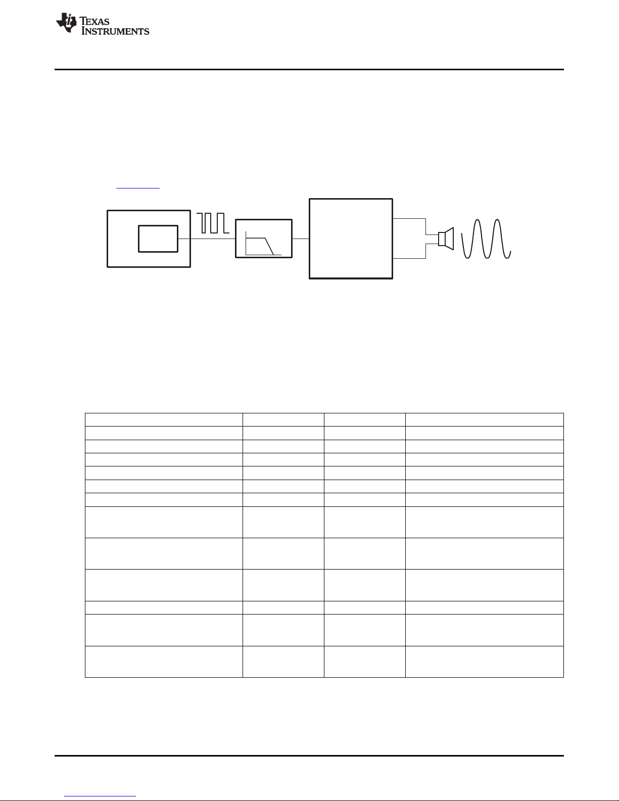
4.5.2 Audio Output Signal Chain
The MSP430F5438A generates a high-frequency PWM signal to emulate the functionality of a DAC. The
duty cycle of the PWM is derived from the ratio between the emulated voltage and the rail of 3.3 V. This
PWM output signal is filtered heavily to emulate a constant voltage value. This output is then connected to
a Texas Instruments TPA301 audio amplifier.
The audio output circuit utilizes the audio amplifier to amplify the filtered output signal from the PWM and
feed the amplified signal into the audio output jack. The amplification is sufficient to support non-amplified
headphones as well as amplified speakers. For more information on the TPA301, see the device data
sheet (SLOS208).
Figure 4-2. Audio Output Signal Chain
4.6 Headers Port X.Y, P10, and RF3
The MSP-EXP430F5438 Experimenter Boards includes three headers that can be used as additional
connections to external hardware or for signal analysis during firmware development, Port x.y, P10, and
RF3. All pins except the GND pin are internally selectable as either general purpose input/output pins or
as described in the adjacent columns of Table 4-3 through Table 4-5.
Headers Port X.Y, P10, and RF3
Table 4-3. Pin Mapping for Header Port x.y
Pin Description Port Pin Port Pin Pin Description
VREF+ out / VeREF+ in P5.0 P5.1 VREF- / VeREFAnalog Input ( A7 ) P6.7 P7.4 Analog Input (A12)
Analog Input (A13) P7.5 P7.6 Analog Input (A14)
Analog Input (A15) P7.7 GND GND
UCA0TXD / UCA0SIMO P3.4 P3.5 UCA0RXD / UCA0SOMI
UCB1STE / UCA1CLK P3.6 P3.7 UCB1SIMO / UCB1SDA
Timer B0 CCR0 Timer B0 CCR1
capture: CCI0A / CCI0B input; P4.0 P4.1 capture: CCI1A/CCI1B input;
compare: Out0 output; compare: Out1 output; (PWM)
Timer B0 CCR2 Timer B0 CCR3
capture: CCI2A/CCI2B input; P4.2 P4.3 capture: CCI3A/CCI3B input;
compare: Out2 output; (PWM) compare: Out3 output; (PWM)
Timer B0 CCR5 Timer B0 CCR6
capture: CCI5A/CCI5B input; P4.5 P4.6 capture: CCI6A/CCI6B input;
compare: Out5 output; (PWM) compare: Out6 output; (PWM)
TB0 clock input / SMCLK output P4.7 P5.4 UCB1SOMI / UCB1SCL
UCB1CLK / UCA1STE P5.5 P7.3 capture: CCI2B input;
Timer A1 CCR0 Timer A1 CCR1
capture: CCI0B input; P8.5 P8.6 capture: CCI1B input;
compare: Out0 output; compare: Out1 output; (PWM)
Timer A1 CCR2
compare: Out2 output; (PWM)
SLAU263F–January 2009–Revised May 2011 Hardware Functional Overview
Submit Documentation Feedback
Copyright © 2009–2011, Texas Instruments Incorporated
21
Page 22

Headers Port X.Y, P10, and RF3
Pin Description Port Pin Port Pin Pin Description
GPIO only P10.7 P10.6 GPIO only
UCA3RXD / UCA3SOMI P10.5 P10.4 UCA3TXD / UCA3SIMO
UCB3CLK / UCA3STE P10.3 P10.2 UCB3SOMI / UCB3SCL
UCB3SIMO / UCB3SDA P10.1 P10.0 UCB3STE / UCA3CLK
Pin Description Port Pin Port Pin Pin Description
Timer A0 CCR3
capture: CCI3A input; P1.4 P11.0
compare: Out3 output; (PWM)
Timer A0 CCR1
capture: CCI1A input; P1.2 P9.4
compare: Out1 output; (PWM)
Timer A0 CCR4
capture: CCI4A input; P1.5 P9.5
compare: Out4 output; (PWM)
SMCLK output P1.6 P8.2 capture: CCI2B input;
Timer A0 CCR2
capture: CCI2A input; P1.3 P1.7 GPIO only
compare: Out2 output; (PWM)
UCB0CLK / UCA0STE UCB0SOMI / UCB0SCL
(RF_SPI_CLK) (RF_MISO)
UCB0SIMO / UCB0SDA UCB0STE / UCA0CLK
(RF_MOSI) (RF_STE)
www.ti.com
Table 4-4. Pin Mapping for Header P10
Table 4-5. Pin Mapping for Header RF3
VCC GND
ACLK output
(divided by 1, 2, 4, 8, 16, or 32)
UCA2TXD / UCA2SIMO
(EZRF_TXD)
UCA2RXD / UCA2SOMI
(EZRF_RXD)
Timer A0 CCR2
compare: Out2 output; (PWM)
Timer A0 CCR1
GND P8.1 capture: CCI1B input;
compare: Out1 output; (PWM)
P3.3 P3.2
P3.1 P3.0
22
Hardware Functional Overview SLAU263F–January 2009–Revised May 2011
Copyright © 2009–2011, Texas Instruments Incorporated
Submit Documentation Feedback
Page 23

5.1 User Experience
This section describes the example software that illustrates various functionalities of the
MSP-EXP430F5438 Experimenter Board. To begin evaluation of the User Experience example software,
ensure that the MSP430F5438A is correctly oriented in the socket before connecting power to the
experimenter board. Pin one should be located at the top-left corner of the socket and aligned with the
small arrow that is visible on the socket (see Figure 1-1).
After the device has been programmed with the example software and the board is supplied with power,
the LCD should load the splash screen displaying the TI logo. Pressing the center direction on the joystick
(push down) starts the normal operation of the board.
5.2 Main Menu
The main menu displays a list of applications and settings that users can choose from. Additionally, the
menu also displays time and battery voltage on the LCD screen. Navigation in this menu can be done with
the joystick (up, down, center to select) and/or the push buttons (S1 to exit, S2 to select/enter). Each
application in the menu is described in the following sections.
In this screen, if there is no action from user within 10 seconds, the board goes into standby mode. By
default, the board returns to active mode if any button is pressed or the board is tilted.
Chapter 5
SLAU263F–January 2009–Revised May 2011
Example Software – User Experience
5.2.1 Clock
Select this option from the main menu to display an analog clock. After 10 seconds, the backlight is
disabled to conserve power.
Press center on the joystick to return to the main menu.
5.2.2 UniBall
UniBall is an accelerometer demonstration in which the user can control the movements of a ball on the
LCD screen by tilting the board. The LCD initially loads the TI logo as the background, and the ball
appears as the dot on the TI logo. The user can tilt the board to move the ball and erase the TI logo in the
process. The TI logo is reset periodically.
Press center on the joystick to return to the main menu.
5.2.3 USB-UART
This application displays a UART terminal to communicate with a host PC via USB cable at 57600 bps.
Users can type in a terminal window to send characters to the LCD screen of the MSP-EXP430F5438
board. The board also sends characters to the PC if there are any actions on the joystick or the push
buttons. Make sure jumpers JP5 (USB TX/RX) are set horizontally to properly communicate with the PC
terminal.
Press center on the joystick to return to the main menu.
Advanced Debugging Tip: When jumpers J5 are connected vertically, the UART connections become an
echo for both the MSP430 and the terminal window.
SLAU263F–January 2009–Revised May 2011 Example Software – User Experience
Submit Documentation Feedback
23
Copyright © 2009–2011, Texas Instruments Incorporated
Page 24

Main Menu
5.2.4 Audio Apps
Selecting Audio Apps takes the user to a sub-menu containing two audio applications. Use the joystick to
highlight either the Voice Recorder application or the FFT application, and press center on the joystick to
select the application.
Select Quit to return to the main menu.
5.2.4.1 Voice Recorder
The voice recorder allows users to record speech into the MSP430F5438 flash memory. Due to the large
size of the flash (256 KB), users can store up to ~20 seconds of speech audio.
• To record, press S1 and speak in normal voice into the microphone located in the bottom left of the
Experimenter Board. The user can record for the entire length allowed by the flash size or stop the
recording any time by pressing S2.
• To playback, press S2. Similarly to recording, the user can stop the playback anytime by pressing S1.
Press center on the joystick to return to the Audio Apps sub-menu.
5.2.4.2 FFT
This application allows users to see the results of a FFT performed on the received data from the
microphone. As higher frequencies are received through the microphone, the spectrum moves towards the
right side of the screen.
Press center on the joystick to return to the Audio Apps sub-menu.
www.ti.com
5.2.5 Power Test
Selecting Power Test takes the user to a sub-menu containing two applications that allow the user to
observe the current consumption of the MSP430F5438A in different operating modes. First, use the
joystick to highlight Active or Low Power, then press center on the joystick to select the application.
Select Quit to return to the main menu.
5.2.5.1 Active
This application allows the user to experiment with the different DCO frequency settings that the
MSP430F5438A supports. The MCLK options are listed on the right column and can be selected by
pressing S2.
The V
The MCLK options are listed on the right column and can be selected by highlighting them with the
joystick. MCLK options written in grey indicate clock rates requiring a higher V
selection. If the test equipment does not facilitate frequency measurement, the user can partially observe
the frequency from the blinking of LED1.
For each setting, the user can measure V
MCLK/SMCLK test points, and the active mode current via the MSP430 power jumper JP1. Pressing S1
turns off the LCD to give a more accurate active mode current measurement. LED2 blinks briefly every 2
seconds while the LCD is off to indicate the board is still active. Pressing any button turns the LCD back
on.
Press center on the joystick to return to the Power Test sub-menu.
5.2.5.2 Low Power
This application allows the user to observe the current consumption of the different low-power modes
supported by the MSP430F5438A. Select a low-power mode configuration using the joystick, then press
center on the joystick to enter the low-power mode. The LCD shuts down to give a more accurate current
reading. The current can be measured via the MSP430 power jumper JP1. Pressing any button turns the
LCD back on and wakes the board from low-power mode.
Select Quit to return to the Power Test sub-menu.
options are listed in the left column and can be selected by highlighting them with the joystick.
CORE
setting than the current
CORE
at the VCORE test point, the DCO frequency at the
CORE
24
Example Software – User Experience SLAU263F–January 2009–Revised May 2011
Copyright © 2009–2011, Texas Instruments Incorporated
Submit Documentation Feedback
Page 25

www.ti.com
5.2.6 ADC Temp
The ADC Temp application demonstrates the use of the ADC with the temperature sensor to measure
ambient temperature using two different methods. Users can observe the current consumption of the two
modes via the MSP430 power jumper JP1. On entering the application, the LCD backlight is turned off so
as not to affect current measurement. Use the joystick to highlight either Flag Poll Mode or Interrupt Mode.
Flag Poll Mode uses software to trigger sampling and ADC conversions, whereas Interrupt Mode is a fully
hardware driven implementation. The temperature in degrees Celsius and Fahrenheit is updated every 2
seconds, as well as the VCC.
Press center on the joystick to return to the main menu.
5.3 Main Menu > Settings Menu
This option allows the user to modify various settings of digital components and calibrate analog sensors
available on board. Select Quit or press S1 to return to the main menu. All settings are stored into the
memory upon exiting the setting menu screen.
In this screen, if there is no action from user within 10 seconds, the board goes into sleep mode. By
default, the board returns to active mode in the main menu if any button is pressed or the board is tilted.
5.3.1 Set Time
This option allows the user to modify the current time by moving up or down to modify the time values and
moving left or right to select either Hour, Minute, or Second.
Press center on the joystick to return to the Settings menu.
Main Menu > Settings Menu
5.3.2 LCD Contrast
This option allows the user to modify the contrast of the LCD by pressing S1 to reduce the contrast and
pressing S2 to increase the contrast.
Press center on the joystick to return to the Settings menu.
5.3.3 LCD Backlight
This option allows the user to modify the backlight of the LCD by pressing S1 to dim the backlight and
pressing S2 to brighten the backlight.
Press center on the joystick to return to the Settings menu.
5.3.4 Accelerometer Settings
The user can recalibrate the accelerometer sensor by pressing up while keeping the board flat and
stationary. This screen also allows the user to specify whether or not the board returns from sleep mode if
the board is tilted. This option can be selected with either S1 for No or S2 for Yes. To select different
digits, press left or right.
Press center on the joystick to return to the Settings menu.
SLAU263F–January 2009–Revised May 2011 Example Software – User Experience
Submit Documentation Feedback
25
Copyright © 2009–2011, Texas Instruments Incorporated
Page 26

26
Example Software – User Experience SLAU263F–January 2009–Revised May 2011
Copyright © 2009–2011, Texas Instruments Incorporated
Submit Documentation Feedback
Page 27

Chapter 6
SLAU263F–January 2009–Revised May 2011
Frequently Asked Questions, References, and Schematics
6.1 Frequently Asked Questions
1. Which devices can be programmed with the Experimenter Board?
The MSP-EXP430F5438 board is designed specifically to demonstrate the MSP40F5438IPZ and the
MSP430F5436IPZ silicon. Future MSP430 devices may be released which are also supported.
2. The MSP430F5438A is no longer accessible via JTAG. is something wrong with the device?
Verify that the jumpers are configured correctly. See Chapter 4 for jumper configuration.
Verify that the target device is powered properly.
If the target is powered locally, verify that the supplied VCCis sufficient to power the board. Check the
device data sheet for the specification.
3. I did every step in the previous question but still could not use or communicate with the device.
In the case that you are using the REV_02, check if you are using the test version of silicon, the
XMS430F5438. Improper programming of the device could lead to a JTAG total lockup condition. The
cause of this problem might be an incorrect device selection when creating a new project in CCS
(selecting XMS430F5438 instead of MSP430F5438) or programming the device without a stable power
source (low battery, switching the Power Selector while programming or absence of the MSP430
power jumper JP1 during programming).
Regardless of the revision of silicon, completely reset the device, first unplug all power sources and
connections (JTAG and USB cables). Set the Power Selector Switch to FET mode. Use a jumper cable
to briefly short one of the GND test points with the 430 PWR test point. The device should now be
released from the lockup state.
4. Does the Experimenter board protect against blowing the JTAG fuse of the target device?
No. Fuse blow capability is inherent to all Flash-based MSP430 devices in order to protect user's
intellectual property. Care must be taken to avoid the enabling of the fuse blow option during
programming that would prevent further access to the MSP430 device(s) via JTAG.
5. I am measuring system current in the range of 30 mA, is this normal?
The LCD and the LCD backlight require a large amount of current (approximately 20 mA to 25 mA) to
operate. This results in a total system current consumption in the range of 30 mA. If the LCD backlight
is on, 30 mA is considered normal.
To ensure the board is OK, disable the LCD and the LCD backlight and measure the current again.
The entire board current consumption should not exceed 10 mA at this state. Note that the current
consumption of the board could vary greatly depending on the optimization of the board configurations
and the applications.
The expected current consumption for the MSP430F5438A in standby mode (LPM3), for example, is
~2 μA. Operating at 1 MHz, the total current consumption should not exceed ~280 μA.
6. The battery option for the Power Selector Switch does not seem to supply enough current for
the Experimenter Board?
The LCD and the LCD backlight require large amount of current to operate. Prolonged operation with
the LCD enabled could drain the batteries at a fast rate. Replace the batteries if the battery voltage
measured drops significantly.
SLAU263F–January 2009–Revised May 2011 Frequently Asked Questions, References, and Schematics
Submit Documentation Feedback
27
Copyright © 2009–2011, Texas Instruments Incorporated
Page 28

References
7. I have trouble reading the LCD clearly. Why is the LCD contrast setting so low?
8. When I run the example code, nothing happens on the LCD.
9. What is the correct orientation of the part in the socket?
10. When I compile the code I get the following error: could not open source file
www.ti.com
The LCD contrast is highly dependent on the voltage of the system. Changing power source from USB
(3.3 V) to batteries (~3 V) could drastically reduce the contrast. Fortunately, the LCD driver supports
adjustable contrast. The specific instruction can be found in the LCD user's guide. The
MSP-EXP430F5438 software driver also provides the function call halLcdSetContrast() to adjust the
contrast in software.
The possible sources of error:
• Check that the SYS PWR jumper (JP2) and the 14-pin JTAG cable are properly connected.
• The contrast settings differ from board to board. Try switching between the different power
connections (FET, USB, BATT) to see if the contrast looks better. The example software also
allows you to increase or decrease the contrast settings.
• Revision 0-03 of the MSP-EXP430F5438 board is incompatible with revision 0-02 (distributed in
limited quantities for the Advanced Technical Conference 2008). The revision number can be found
on the back of the Experimenter Board. Revision 0-03 has P8.7 grounded to differentiate itself from
previous revisions of the board, and the example software uses the internal pullup resistor on P8.7
to check this pin for compatibility with the software version. If the software and hardware do not
match, the code spins in a while(1) loop at the beginning of the UserExperience() function of
UserExperience.c.
Pin 1, denoted by a single small indented circle, should line up with the arrow on the socket.
..\MSP-EXP430F5438 HAL\hal_MSP-EXP430F5438.h.
Eclipse does not accept paths that are too long. Move the project higher in your directory structure –
towards the C:/ directory – and the project should compile without error.
6.2 References
1. MSP430x5xx/MSP430x6xx Family User's Guide (SLAU208)
2. MSP430F543xA, MSP430F541xA Mixed Signal Microcontroller data sheet (SLAS655)
3. Code Composer Studio (CCStudio) Integrated Development Environment (IDE)
(http://focus.ti.com/docs/toolsw/folders/print/msp-ccstudio.html)
4. MSP430 Interface to CC1100/2500 Code Library (PDF: SLAA325, associated files: (SLAA325.ZIP)
5. TPA301: 350-mW Mono Audio Power Amplifier data sheet (SLOS208)
6. ADXL322 data sheet (www.analog.com)
7. Hitachi HD66753 LCD data sheet
8. Hitachi HD66753 LCD user's guide
28
Frequently Asked Questions, References, and Schematics SLAU263F– January 2009–Revised May 2011
Copyright © 2009–2011, Texas Instruments Incorporated
Submit Documentation Feedback
Page 29

www.ti.com
6.3 Schematics
The original Eagle CAD schematics and Gerber files are available for download (SLAC228).
Schematics
SLAU263F–January 2009–Revised May 2011 Frequently Asked Questions, References, and Schematics
Submit Documentation Feedback
29
Copyright © 2009–2011, Texas Instruments Incorporated
Page 30

Schematics
www.ti.com
Figure 6-1. MSP430F5438A and Peripherals Schematic
30
Frequently Asked Questions, References, and Schematics SLAU263F–January 2009–Revised May 2011
Submit Documentation Feedback
Copyright © 2009–2011, Texas Instruments Incorporated
Page 31

www.ti.com
Schematics
Figure 6-2. USB to UART Schematic
31
SLAU263F–January 2009–Revised May 2011 Frequently Asked Questions, References, and Schematics
Submit Documentation Feedback
Copyright © 2009–2011, Texas Instruments Incorporated
Page 32

IMPORTANT NOTICE
Texas Instruments Incorporated and its subsidiaries (TI) reserve the right to make corrections, modifications, enhancements, improvements,
and other changes to its products and services at any time and to discontinue any product or service without notice. Customers should
obtain the latest relevant information before placing orders and should verify that such information is current and complete. All products are
sold subject to TI’s terms and conditions of sale supplied at the time of order acknowledgment.
TI warrants performance of its hardware products to the specifications applicable at the time of sale in accordance with TI’s standard
warranty. Testing and other quality control techniques are used to the extent TI deems necessary to support this warranty. Except where
mandated by government requirements, testing of all parameters of each product is not necessarily performed.
TI assumes no liability for applications assistance or customer product design. Customers are responsible for their products and
applications using TI components. To minimize the risks associated with customer products and applications, customers should provide
adequate design and operating safeguards.
TI does not warrant or represent that any license, either express or implied, is granted under any TI patent right, copyright, mask work right,
or other TI intellectual property right relating to any combination, machine, or process in which TI products or services are used. Information
published by TI regarding third-party products or services does not constitute a license from TI to use such products or services or a
warranty or endorsement thereof. Use of such information may require a license from a third party under the patents or other intellectual
property of the third party, or a license from TI under the patents or other intellectual property of TI.
Reproduction of TI information in TI data books or data sheets is permissible only if reproduction is without alteration and is accompanied
by all associated warranties, conditions, limitations, and notices. Reproduction of this information with alteration is an unfair and deceptive
business practice. TI is not responsible or liable for such altered documentation. Information of third parties may be subject to additional
restrictions.
Resale of TI products or services with statements different from or beyond the parameters stated by TI for that product or service voids all
express and any implied warranties for the associated TI product or service and is an unfair and deceptive business practice. TI is not
responsible or liable for any such statements.
TI products are not authorized for use in safety-critical applications (such as life support) where a failure of the TI product would reasonably
be expected to cause severe personal injury or death, unless officers of the parties have executed an agreement specifically governing
such use. Buyers represent that they have all necessary expertise in the safety and regulatory ramifications of their applications, and
acknowledge and agree that they are solely responsible for all legal, regulatory and safety-related requirements concerning their products
and any use of TI products in such safety-critical applications, notwithstanding any applications-related information or support that may be
provided by TI. Further, Buyers must fully indemnify TI and its representatives against any damages arising out of the use of TI products in
such safety-critical applications.
TI products are neither designed nor intended for use in military/aerospace applications or environments unless the TI products are
specifically designated by TI as military-grade or "enhanced plastic." Only products designated by TI as military-grade meet military
specifications. Buyers acknowledge and agree that any such use of TI products which TI has not designated as military-grade is solely at
the Buyer's risk, and that they are solely responsible for compliance with all legal and regulatory requirements in connection with such use.
TI products are neither designed nor intended for use in automotive applications or environments unless the specific TI products are
designated by TI as compliant with ISO/TS 16949 requirements. Buyers acknowledge and agree that, if they use any non-designated
products in automotive applications, TI will not be responsible for any failure to meet such requirements.
Following are URLs where you can obtain information on other Texas Instruments products and application solutions:
Products Applications
Audio www.ti.com/audio Communications and Telecom www.ti.com/communications
Amplifiers amplifier.ti.com Computers and Peripherals www.ti.com/computers
Data Converters dataconverter.ti.com Consumer Electronics www.ti.com/consumer-apps
DLP® Products www.dlp.com Energy and Lighting www.ti.com/energy
DSP dsp.ti.com Industrial www.ti.com/industrial
Clocks and Timers www.ti.com/clocks Medical www.ti.com/medical
Interface interface.ti.com Security www.ti.com/security
Logic logic.ti.com Space, Avionics and Defense www.ti.com/space-avionics-defense
Power Mgmt power.ti.com Transportation and www.ti.com/automotive
Microcontrollers microcontroller.ti.com Video and Imaging www.ti.com/video
RFID www.ti-rfid.com Wireless www.ti.com/wireless-apps
RF/IF and ZigBee® Solutions www.ti.com/lprf
TI E2E Community Home Page e2e.ti.com
Automotive
Mailing Address: Texas Instruments, Post Office Box 655303, Dallas, Texas 75265
Copyright © 2011, Texas Instruments Incorporated
 Loading...