

Page 1

DLP®NIRscan™ Nano EVM User's Guide
User's Guide
Literature Number: DLPU030B
June 2015–Revised July 2015
Page 2

Contents
Preface ........................................................................................................................................ 6
1 DLP NIRscan Nano Overview ................................................................................................ 8
1.1 Introduction ................................................................................................................... 8
1.2 What is the DLP NIRscan Nano EVM? ................................................................................... 8
1.2.1 Optical Engine....................................................................................................... 9
1.2.2 DLP NIRscan Nano Electronics................................................................................. 12
1.2.3 Connections........................................................................................................ 14
2 Getting Started................................................................................................................... 18
2.1 Operating Modes ........................................................................................................... 18
2.1.1 USB Connection................................................................................................... 18
2.1.2 Bluetooth Connection............................................................................................. 19
3 Operating the DLP NIRscan Nano EVM ................................................................................. 20
3.1 NIRscan Nano GUI......................................................................................................... 20
3.1.1 Scanning a Sample ............................................................................................... 22
3.1.2 Displaying Previous Scans ...................................................................................... 27
3.1.3 Transferring Scans Stored in microSD Card .................................................................. 28
3.1.4 Utilities.............................................................................................................. 29
4 DLP NIRscan Nano Hardware............................................................................................... 31
4.1 External Power Supply Requirements .................................................................................. 31
5 DLP NIRscan Nano Software................................................................................................ 35
5.1 Overview..................................................................................................................... 35
5.1.1 TI RTOS ............................................................................................................ 35
5.1.2 TivaWare ........................................................................................................... 36
5.1.3 USB Driver ......................................................................................................... 36
5.1.4 SDSPI Driver ...................................................................................................... 36
5.1.5 Bluetopia Stack.................................................................................................... 36
5.1.6 DLP Spectrum Library ............................................................................................ 37
5.1.7 DLP Spectrum Library Workflow ................................................................................ 37
5.2 Software System Overview ............................................................................................... 39
5.3 Bluetooth Client App Workflow........................................................................................... 40
5.3.1 Bluetooth Client Establishing a Connection.................................................................... 40
5.3.2 Bluetooth Client GATT Profiles.................................................................................. 41
6 iOS App............................................................................................................................. 45
6.1 NanoScan iOS App ........................................................................................................ 45
A Installing the DLP NIRscan Nano Software ............................................................................ 48
A.1 DLP NIRscan Nano Software Installation............................................................................... 48
B Required Tools to Compile Tiva Software.............................................................................. 49
B.1 Tiva Tools Installation...................................................................................................... 49
B.1.1 Code Composer Studio Installation............................................................................. 49
B.1.2 Updating TI-RTOS ................................................................................................ 49
C How to Compile Tiva Source Code ....................................................................................... 51
C.1 Tiva Libraries Compilation ................................................................................................ 51
C.1.1 Tiva driverlib Compilation ........................................................................................ 51
2
Contents DLPU030B–June 2015–Revised July 2015
Copyright © 2015, Texas Instruments Incorporated
Submit Documentation Feedback
Page 3

www.ti.com
C.1.2 Tiva usblib Library................................................................................................. 51
C.1.3 DLP Spectrum Library ............................................................................................ 51
C.2 Tiva Main Source........................................................................................................... 51
C.3 Project Settings............................................................................................................. 52
D Required Tools to Compile NIRscan Nano GUI....................................................................... 53
D.1 NIRscan Nano GUI......................................................................................................... 53
D.1.1 Compiling the DLP Spectrum Library........................................................................... 53
D.1.2 Compiling NIRscan Nano GUI................................................................................... 53
E Tiva EEPROM Contents....................................................................................................... 54
E.1 Tiva EEPROM .............................................................................................................. 54
F DLP NIRscan Nano Connectors............................................................................................ 55
F.1 Battery Connector.......................................................................................................... 55
F.2 Battery Thermistor Connector ............................................................................................ 55
F.3 Expansion Connector...................................................................................................... 55
F.4 JTAG Connector............................................................................................................ 56
F.5 Trigger Connector.......................................................................................................... 56
G DLP NIRscan Nano Command Description............................................................................ 58
G.1 Command Handler Supported Commands ............................................................................. 58
H DLP NIRscan Nano USB Communications............................................................................. 62
I DLP NIRscan Nano Bluetooth Communications..................................................................... 65
I.1 Bluetooth Communications ............................................................................................... 65
I.1.1 GATT Supported Services ....................................................................................... 65
I.2 Bluetooth Packets.......................................................................................................... 71
Revision B History....................................................................................................................... 72
Revision A History....................................................................................................................... 72
DLPU030B–June 2015–Revised July 2015 Contents
Submit Documentation Feedback
Copyright © 2015, Texas Instruments Incorporated
3
Page 4

www.ti.com
List of Figures
1. DLP NIRscan Nano Evaluation Module .................................................................................. 6
1-1. DLP NIRscan Nano Block Diagram ....................................................................................... 9
1-2. DLP NIRscan Nano Optical Engine...................................................................................... 10
1-3. DLP NIRscan Nano Dimensions ......................................................................................... 11
1-4. DLP NIRscan Connectors (Rear View).................................................................................. 14
1-5. DLP NIRscan Connectors (Front View) ................................................................................. 15
1-6. DLP NIRscan Nano Button Locations ................................................................................... 16
1-7. DLP NIRscan Nano LED Locations...................................................................................... 17
3-1. DLP NIRscanNano GUI Information Screen............................................................................ 21
3-2. DLP NIRscanNano GUI Scan Screen................................................................................... 22
3-3. DLP NIRscanNano GUI Scan Configuration Dialog ................................................................... 24
3-4. DLP NIRscan Nano GUI Scan Select Menu............................................................................ 25
3-5. Absorbance Spectrum of Aspirin......................................................................................... 26
3-6. Displaying Previous Scans................................................................................................ 27
3-7. Number of Scans Detected on microSD Card.......................................................................... 28
3-8. 3 Scans Transferred from microSD Card ............................................................................... 29
3-9. DLP NIRscan Nano GUI Uitlities Screen................................................................................ 30
4-1. DLP NIRscan Nano Power Block Diagram ............................................................................. 32
4-2. DLP NIRscan Nano Tiva Connections .................................................................................. 33
4-3. DLP NIRscan Nano Tiva Connections to DLPC150 Controller Board .............................................. 34
5-1. DLP NIRscan Nano Software Architecture ............................................................................. 35
5-2. DLP Spectrum Library View Configuration Information Workflow ................................................... 37
5-3. DLP Spectrum Library Decode Scan Results Workflow .............................................................. 38
5-4. DLP Spectrum Library Compute Reference Workflow ................................................................ 38
5-5. DLP Spectrum Library Compute and Display Reflectance Workflow ............................................... 38
5-6. DLP Spectrum Library Compute and Display Absorbance ........................................................... 39
5-7. DLP NIRscan Nano Software Block Diagram .......................................................................... 40
5-8. Bluetooth Low Energy Connection Workflow........................................................................... 40
5-9. GATT Calibration Service Workflow..................................................................................... 41
5-10. GATT Scan Configuration Service Workflow........................................................................... 42
5-11. GATT Scan Data Service Workflow ..................................................................................... 43
5-12. GATT Scan Data Service Workflow to Display an Existing Scan or Performing a New Scan................... 44
6-1. NanoScan Main Screen ................................................................................................... 45
6-2. NanoScan Scan Screen................................................................................................... 46
6-3. NanoScan Scan Plot Screen ............................................................................................. 47
H-1. USB HID Protocol .......................................................................................................... 62
4
List of Figures DLPU030B–June 2015–Revised July 2015
Copyright © 2015, Texas Instruments Incorporated
Submit Documentation Feedback
Page 5

www.ti.com
1-1. DLP NIRscan Nano EVM Specifications................................................................................ 11
1-2. DLP NIRscan Nano Electronics.......................................................................................... 13
1-3. DLP NIRscan Nano Connectors.......................................................................................... 14
1-4. DLP NIRscan Nano LED Indicators...................................................................................... 17
3-1. Typical Scan Configuration Parameters................................................................................. 23
E-1. Tiva EEPROM .............................................................................................................. 54
F-1. Battery Power Connector (Tiva J6) ...................................................................................... 55
F-2. Battery Thermistor Connector (Tiva J7)................................................................................. 55
F-3. Expansion Connector (Tiva J3)........................................................................................... 56
F-4. ARM Cortex 10-pin JTAG Connector (Tiva J4) ........................................................................ 56
F-5. Trigger Connector (DLPC150 J500)..................................................................................... 57
G-1. DLP NIRscan Nano Supported Commands ............................................................................ 58
I-1. Device Information Service (DIS) ........................................................................................ 66
I-2. Battery Service (BAS) ..................................................................................................... 66
I-3. GATT General Information Service...................................................................................... 67
I-4. GATT Date and Time Service ............................................................................................ 68
I-5. GATT Calibration Information Service................................................................................... 68
I-6. GATT Scan Configuration Information Service......................................................................... 69
I-7. GATT Scan Data Information Service................................................................................... 69
List of Tables
DLPU030B–June 2015–Revised July 2015 List of Tables
Submit Documentation Feedback
Copyright © 2015, Texas Instruments Incorporated
5
Page 6
About This Guide
The DLP®NIRscan™ Nano EVM is a third-party implementation of the next generation DLP reference
design to enable faster development cycles for mobile spectrometer applications.
This guide is an introductory document for the DLP NIRscan Nano EVM that provides an overview of the
system and the system software.
Preface
DLPU030B–June 2015–Revised July 2015
Read This First
Figure 1. DLP NIRscan Nano Evaluation Module
NIRscan, Tiva, TivaWare, SimpleLink, Code Composer Studio are trademarks of Texas Instruments.
DLP is a registered trademark of Texas Instruments.
ARM is a registered trademark of ARM Limited.
Apple, iPhone, iPad are registered trademarks of Apple Inc.
Bluetooth is a registered trademark of Bluetooth SIG.
Windows is a registered trademark of Microsoft Corporation.
All other trademarks are the property of their respective owners.
6
Read This First DLPU030B–June 2015–Revised July 2015
Copyright © 2015, Texas Instruments Incorporated
Submit Documentation Feedback
Page 7

www.ti.com
Related Documentation from TI
• DLP2010NIR data sheet: DLP 0.2 WVGA Near-Infrared DMD, DLPS059
• DLPC150 data sheet: DLPC150 DLP Digital Controller for Advanced Light Control, DLPS048
• DLPC150 programmer's guide: DLPC150 Programmer’s Guide User's Guide, DLPU031
• DLP design guide: DLP Spectrometer Design Considerations, DLPA049
• Tiva™ TM4C1297 data sheet: Tiva TM4C1297NCZAD Microcontroller Data Sheet SPMS435
• TivaWare™ USB library: TivaWare USB Library User's Guide, SPMU297
• TivaWare™ peripheral driver library: TivaWare Peripheral Driver Library User's Guide, SPMU298
• TI-RTOS 2.10: TI-RTOS 2.10 User's Guide, SPRUHD4
• CC2564MODN data sheet:CC2564MODN Bluetooth®Host Controller Interface Module, SWRS160
• ADS1255 data sheet:Very Low Noise, 24-Bit Analog-to-Digital Converter Data Sheet, SBAS288
If You Need Assistance
Search the DLP and MEMS TI E2E Community Support forums.
Search the TM4C Microcontrollers TI E2E Community Support forums.
Search the Bluetooth®CC256x TI E2E Community Support forums.
Search the SimpleLink™ Bluetooth®CC256x Wiki.
Related Documentation from TI
DLPU030B–June 2015–Revised July 2015 Read This First
Submit Documentation Feedback
Copyright © 2015, Texas Instruments Incorporated
7
Page 8
1.1 Introduction
The DLP® NIRscan Nano™ EVM is a complete evaluation module to design a high performance,
affordable near-infrared portable spectrometer. This flexible tool contains everything a designer needs to
start developing a DLP-based spectrometer right out of the box. DLP technology enables handheld
spectral analyzers for use in the food, pharmaceutical, oil and gas, medical, security, and other emerging
industries to deliver lab performance levels in the field. The EVM contains the DLP2010NIR digital
micromirror device, DLPC150 digital controller, and DLPA2005 integrated power management
components. This technology brings together a set of components providing an efficient and compelling
spectroscopy system solution for:
• Portable process analyzers
• Ultra-mobile spectrometer
The new DLP2010NIR DMD is optimized for operation at wavelengths between 700 and 2500 nm. The
DLP NIRscan Nano EVM is one possible implementation of this new DLP technology, operating from 900
to 1700 nm.
Chapter 1
DLPU030B–June 2015–Revised July 2015
DLP NIRscan Nano Overview
1.2 What is the DLP NIRscan Nano EVM?
The DLP NIRscan Nano EVM is a complete NIR spectrometer EVM using DLP technology. The EVM
package includes:
• Near-infrared optomechanical spectrometer engine optimized for 900 to 1700 nm wavelength range:
– Reflective illumination module with two integrated infrared lamps
– 1.69-mm × 0.25-mm input slit
– Collimating lenses
– 885-nm long wavepass filter
– Reflective diffraction grating
– Focusing lenses
– DLP2010NIR DMD (0.2-inch WVGA, 854 × 480 orthogonal pixel, NIR optimized)
– Collection optics
– 1-mm single-pixel InGaAs non-cooled detector
• Electronics subsystem with the electronics consisting of four boards:
– Microcontroller board
• Tiva TM4C1297 microprocessor for system control operating at 120 MHz
• 32MB SDRAM for pattern storage
• Power management with Lithium-polymer or Lithium-ion battery charging circuits using bq24250
• CC2564MODN Bluetooth Low Energy module for Bluetooth 4.0 connectivity
• USB micro connector for USB connectivity
• microSD card slot for external data storage
• HDC1000 humidity and temperature sensor
– DLP controller board
• DLPC150 DLP controller
• DLPA2005 integrated power management circuit for DMD and DLP controller supplies
8
DLP NIRscan Nano Overview DLPU030B–June 2015–Revised July 2015
Copyright © 2015, Texas Instruments Incorporated
Submit Documentation Feedback
Page 9
Microcontroller Board
DMD Board
DLP Controller Board
Detector Board
DLP Controller
DLPC150
Flash
DMD
DLP2010NIR
DMD Flex
24-bit ADC
ADS1255
SPI
Microprocessor
TM4C129
USB Slave
I2C2
Amplifier
OPA2376
InGaAs
Detector
24bit RGB
Power
Management
TPS63036
TPS81256
TPS82671
TPS386596
TPS22904
SSI2
I2C 24bit RGB
SSSI3
UART3
Bluetooth
CC2564MODN
SSI1
PMIC
DLPA2005
LVDS
SPI
SPI
Ctrl
Ctrl
Grating
Processor
Interface
RF/IF
Amplifier
Logic
Power
ADC/DAC
Clocks
Others
LEGEND
Battery
Charger
BQ24250
Sample
Reflective
Module
Li-Polymer
Battery*
*Battery Not Included
Amp
OPA350
2.5V Ref
REF5025
I2C6
Hum & Temp Sensor
HDC1000
SENS
IR Temp
TMP006
I2C7
EPI0
SDRAM
AS4C16M16S (32MB)
I2C9
SSI0
Exp
Conn
UART4
Triggers
GPIOs
LEDs Buttons
On/Off
Bluetooth
Scan
On/Off Scan/BT Pair
JTAG
ARM
10pin header
Lamp Driver
OPA567INA213TPS81256
T
*Thermistor Not Included
Thermistor
charging
USB Power
www.ti.com
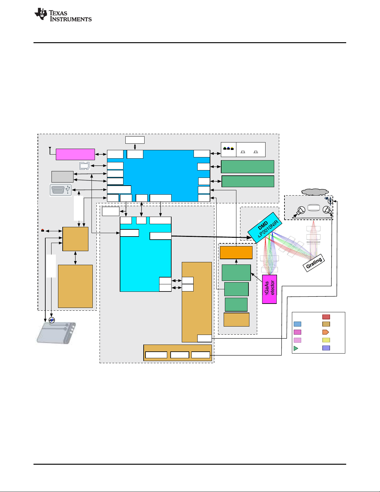
Figure 1-1 shows the NIRscan Nano hardware block diagram.
What is the DLP NIRscan Nano EVM?
• Constant current lamp driver based on OPA567 and monitored by INA213
– Detector board
• Low-noise differential amplifier circuit
• ADS1255 30 kSPS analog-to-digital converter (ADC) with SPI
• TMP006 thermopile sensor for detector and ambient temperature measurement
• 1-mm non-cooled Hamamatsu G12180-010A InGaAs photodiode
– DMD board
• DLP2010NIR near-infrared digital micromirror device
1.2.1 Optical Engine
DLPU030B–June 2015–Revised July 2015 DLP NIRscan Nano Overview
Submit Documentation Feedback
Figure 1-1. DLP NIRscan Nano Block Diagram
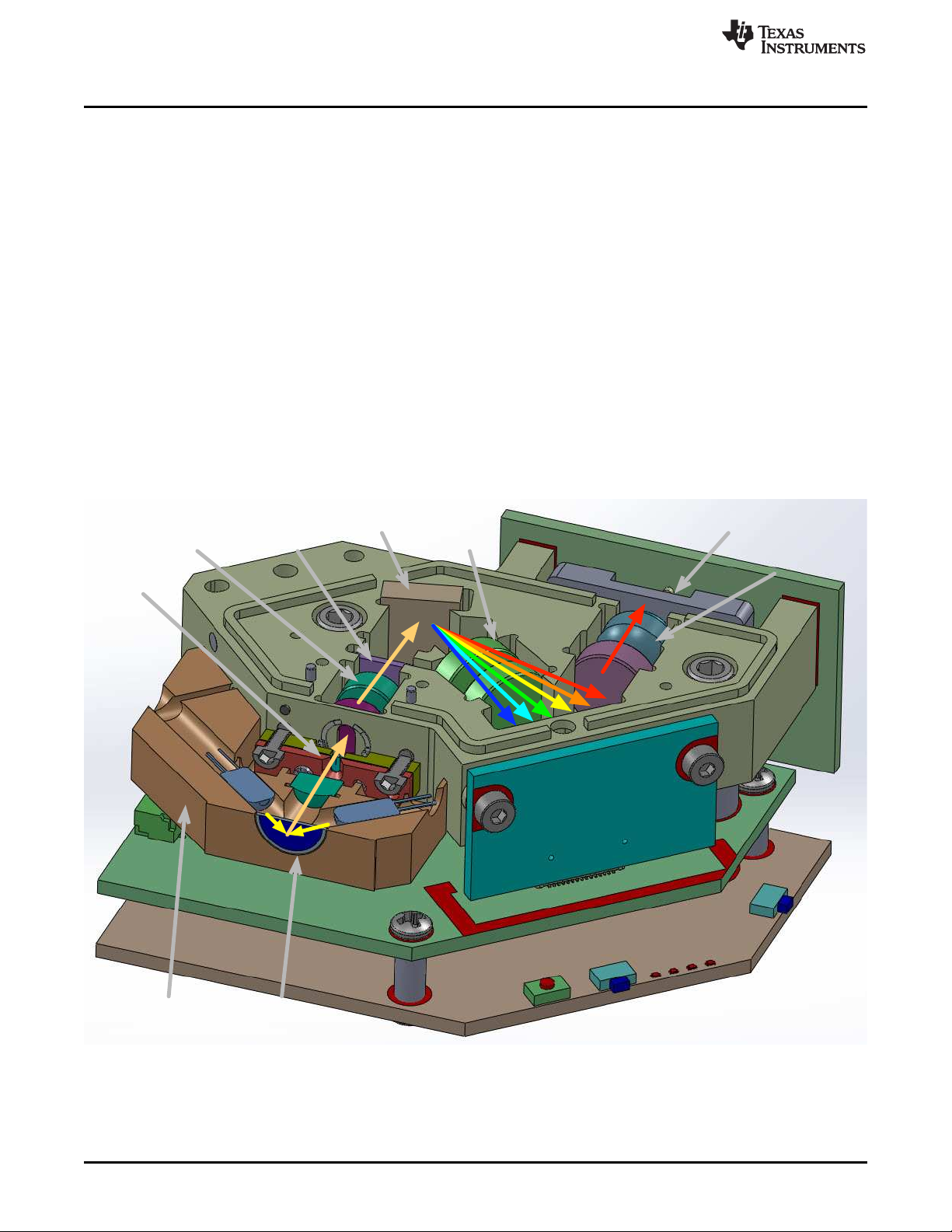
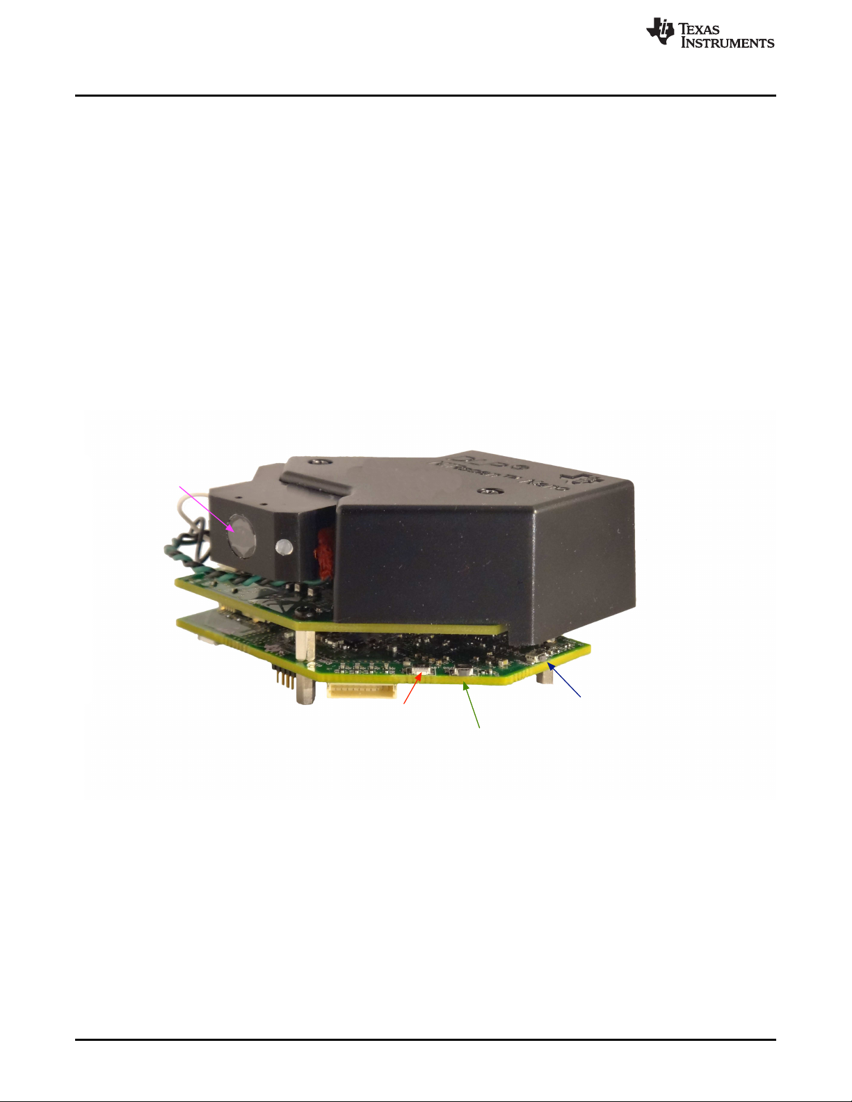
The DLP NIRscan Nano EVM spectrometer optical engine is mounted on top of the electronics
subsystem. The configuration is a post-dispersive architecture with a removable reflectance sample
module. The reflectance module includes two lens-end broadband tungsten filament lamps. In this specific
implementation, depicted in Figure 1-2, a sample is placed against the sapphire front window of the
reflectance head. During a scan, the sample absorbs a specific amount of NIR light and diffusely reflects
the non-absorbed light into the system. The amount of light absorbed at each wavelength is dependent on
the molecular makeup of the material, and is specific to that material, a chemical fingerprint. The light
diffusely reflected from the sample is gathered by the collection lens and focused into the optical engine
Copyright © 2015, Texas Instruments Incorporated
9
Page 10
Collimating
Lenses
Grating
Wavepass
Filter
Slit
Lamp
Lamp
DMD Board
Microcontroller Board
DLP Controller Board
Detector Board
Detector
Sample
Window
Focusing
Lenses
Collection
Lenses
Illumination
Module
What is the DLP NIRscan Nano EVM?
through the input slit. The slit size is chosen to balance wavelength resolution with SNR of the
spectrometer. This spectrometer uses a 25-μm wide by 1.69-mm tall slit. The light that passes through the
slit is collimated by the first set of lenses, passes through an 885-nm long wavepass filter, and then strikes
a reflective grating. This grating, in combination with the focusing lens, disperses the light into its
constituent wavelengths. The focusing lenses form an image of the slit at the DLP2010NIR DMD. Different
wavelengths of this slit image are spread horizontally across the DLP2010NIR DMD. The optical system
images 900-nm wavelengths to one end of the DMD and 1700-nm to the other end, with all other
wavelengths dispersed in between. When specific DMD columns are selected as on, or tilted to the +17°
position, the energy reflected by the selected columns is directed through the collection optics to the single
pixel InGaAs detector. All other DMD columns selected as off, or tilted to the –17° position, diverts the
unselected wavelengths away from the detector optical path so as not to interfere with the selected
wavelength measurement.
The DLP NIRscan Nano reflectance module operates by illuminating the sample under test at an angle so
that specular reflections are not collected, while gathering and focusing diffuse reflections to the slit. The
illuminating lamps are designated as lens-end lamps because the front end of the glass bulb is formed into
a lens that directs more light from the filament to the sample test region. The collection lens gathers
collimated light from a 2.5-mm diameter region at the sample window. The size of the collection region
was matched to the nominal illumination spot size created by the lens-end lamps. This requires that the
sample be placed directly against the sapphire window, where the two angled light source paths intersect
the collection vision cone of the lens. If the sample is shifted farther away from the window, the sample
may not receive enough illumination for the system to perform an accurate scan.
www.ti.com
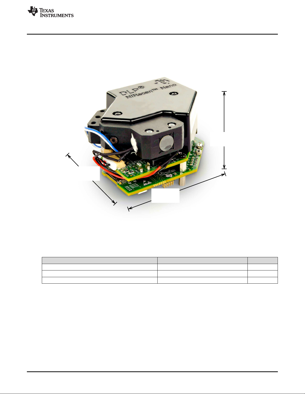
The optical engine footprint drives the size of the DLP NIRscan Nano EVM. The NIRscan Nano EVM
measures approximately 62-mm long, 58-mm wide, and 36-mm tall as shown in Figure 1-3.
Figure 1-2. DLP NIRscan Nano Optical Engine
10
DLP NIRscan Nano Overview DLPU030B–June 2015–Revised July 2015
Copyright © 2015, Texas Instruments Incorporated
Submit Documentation Feedback
Page 11
58 mm
62 mm
36 mm
www.ti.com
What is the DLP NIRscan Nano EVM?
Figure 1-3. DLP NIRscan Nano Dimensions
Table 1-1 lists the specifications of the DLP NIRscan Nano EVM.
Table 1-1. DLP NIRscan Nano EVM Specifications
PARAMETER MIN TYP MAX UNIT
Supported wavelengths 900 1700 nm
Optical resolution 10 12 nm
Lamp power 1.4 W
DLPU030B–June 2015–Revised July 2015 DLP NIRscan Nano Overview
Submit Documentation Feedback
Copyright © 2015, Texas Instruments Incorporated
11
Page 12

What is the DLP NIRscan Nano EVM?
1.2.2 DLP NIRscan Nano Electronics
The DLP NIRscan Nano EVM contains the following four boards:
• Microcontroller board: The Microcontroller board is the largest board in the DLP NIRscan Nano EVM.
This board includes the following:
– Tiva TM4C1297 microcontroller: The Tiva processor controls the whole system. The Tiva runs the
TI realtime operating system (RTOS), the Bluetopia stack, and the spectroscopy software. When it
receives a scan command through USB, Bluetooth, or through pressing the scan button, the Tiva
streams through its LCD interface a set of unique wavelength specific patterns to the DLPC150 for
display on the DMD while synchronizing the sampling of the spectrometer's ADC. An external
32MB SDRAM allows for additional code storage and stores the pattern buffer streamed to the
DLPC150.
– External interfaces: The Microcontroller board provides two main interfaces to the outside world:
USB and Bluetooth Low Energy. To leverage the DLP NIRscan EVM platform for new product
development using the Tiva processor, the microcontroller board also contains a Tiva debug JTAG
port, which can be used with Code Composer Studio™ emulation software and XDS100, XDS200,
or XDS560 emulators. The Microcontroller board also includes and expansion connector with SPI,
UART, and GPIO capability for connection to external systems.
– Battery charging circuits: An optional 3.7-V Lithium-Ion or Lithium-Polymer can be added to power
the system. The on-board power management circuits of the bq24250 device take power from USB
and simultaneously charge the battery if its voltage is below 4.2 V at up to 1-A charge current. The
bq24250 also monitors an optional thermistor for battery temperature monitoring during charge.
– microSD card connector: The microSD card connector allows additional storage for scan data when
the system is not connected to a PC nor iOS device.
– HDC1000 humidity and temperature sensor: Measures the humidity and temperature of the system.
These values are captured with each scan.
• DLP controller board: The DLPC150 controller board is the second largest board in the DLP NIRscan
Nano EVM. This board includes the following:
– DLPC150 controller: The DLPC150 receives the pattern data from the Tiva TM4C1297 processor
over a 24-bit RGB bus. The DLPC150 decodes the pattern information and converts the information
into the correct format for the DLP2010NIR DMD. The DLPC150 controls and synchronizes all the
DMD signals, thereby directing each individual mirror to its desired state.
– DLPA2005 PMIC: The DLPA2005 is a power management IC that controls all the supplies to the
DLP2010NIR DMD and the DMD interface portion of the DLPC150 supplies.
– Lamp driver circuit: To provide constant current to the near-infrared lamps, a OPA567 based power
amplifier circuit regulates the current to the lamps to 280 mA at 5 V based on the voltage across a
sense resistor monitored by the INA213 current shunt monitor.
• Detector board: The detector board includes the following:
– Transimpedance low-noise amplifier: Amplifies the signal form the InGaAs detector to the ADC.
– ADS1255 ADC: Converts the amplified signal of the InGaAs detector into a 24-bit value for Tiva
processing.
– TMP006 thermopile sensor: Measures the InGaAs detector temperature and ambient temperature
of the system. These values are captured with each scan.
– 1-mm non-cooled Hamamatsu G12180-010A InGaAs photodiode
• DMD board: The DMD board includes the DLP near-infrared digital micromirror.
The DLP NIRscan Nano electronics contain many devices manufactured by Texas Instruments. Table 1-2
lists the main parts and their functions.
www.ti.com
12
DLP NIRscan Nano Overview DLPU030B–June 2015–Revised July 2015
Copyright © 2015, Texas Instruments Incorporated
Submit Documentation Feedback
Page 13
www.ti.com
What is the DLP NIRscan Nano EVM?
Table 1-2. DLP NIRscan Nano Electronics
Device Electronics Type Description
TM4C1297 Microprocessor
bq24250 Battery charger phases: trickle charge, precharge, constant current, and
CC2465MODN host controller
HDC1000 Sensor
TPS63036
TPS81256
TPS82671
TPS386596 Quad reset supervisor
TPS22904 Load switch supplies 1.8 V for Bluetooth circuits.
DLPC150 DLP
DLPA2005
TPS81256 Power management
OPA567 Power amplifier 2-A power amplifier that supplies 280-mA lamp current.
INA213 Analog monitor
ADS1255 Analog
REF5025 Power management
OPA2376 Detector board
OPA350
TMP006 Sensor
DLP2010NIR DMD board DLP DLP near-infrared digital micromirror
Electronic
Subsystem
Microcontroller
board
DLP controller
board
Cortex-M4 microprocessor operating at 120 MHz with
integrated 1MB flash, 256K SRAM, and USB 2.0 interface.
Single cell Lithium-Ion or Lithium-Polymer battery charger with
up to 1-A charge current from USB. Battery is charged in four
constant voltage. In all charge phases, an optional battery pack
thermistor monitors the battery temperature for safe charging.
Bluetooth Low Energy
interface module
Power management
DLP power DLP power management integrated circuit that powers the DLP
management 1.8-V, 10-V, 18-V, and –14-V supplies.
Precision amplifier
Single chip Bluetooth 4.1 Low Energy subsystem module with
on-board antenna.
Low power, high accuracy temperature and humidity sensor
with 14-bit resolution.
High-efficiency buck-boost converter in wafer chip scale
package supplies 3.3 V.
High-efficiency step-up converter in microSIP package supplies
5.0 V for analog circuits.
High-efficiency step-down converter in microSIP package
supplies 1.8 V.
DLP digital controller for advanced light control. The Tiva
microprocessor in conjunction with the DLPC150 controls
individual DLP2010NIR micromirrors to reflect specific
wavelengths of light to a single point InGaAs detector.
High efficiency step-up converter in microSIP package that
supplies the 5 V for the lamp driver
Voltage output, current-shunt monitor that monitors lamp
current.
Very-low-noise 24-bit analog-to-digital converter. Converts the
analog output of the InGaAs detector into a 24-bit digital value.
Low-noise, very-low-drift, precision voltage reference that
provides the 2.5-V reference for the transimpedance amplifier.
Low-noise precision operational amplifier. Used as a
transimpedance amplifier for the InGaAs detector.
High-speed operation amplifier that buffers the 2.5-V reference
voltage of the transimpedance amplifier.
Infrared thermopile sensor that measures ambient and detector
temperature
DLPU030B–June 2015–Revised July 2015 DLP NIRscan Nano Overview
Submit Documentation Feedback
Copyright © 2015, Texas Instruments Incorporated
13
Page 14
microSD
Battery
USB
Lamp
Battery
Thermistor
Lamp
Photodetector
Detector
What is the DLP NIRscan Nano EVM?
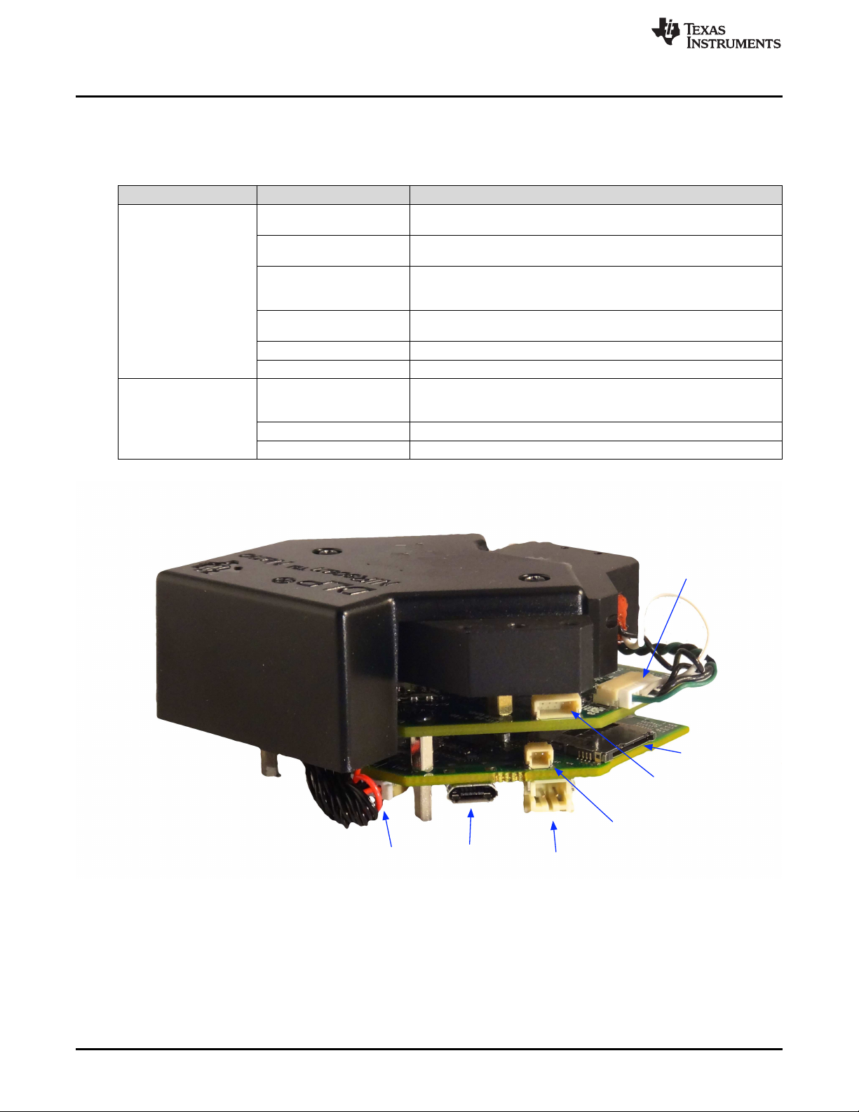
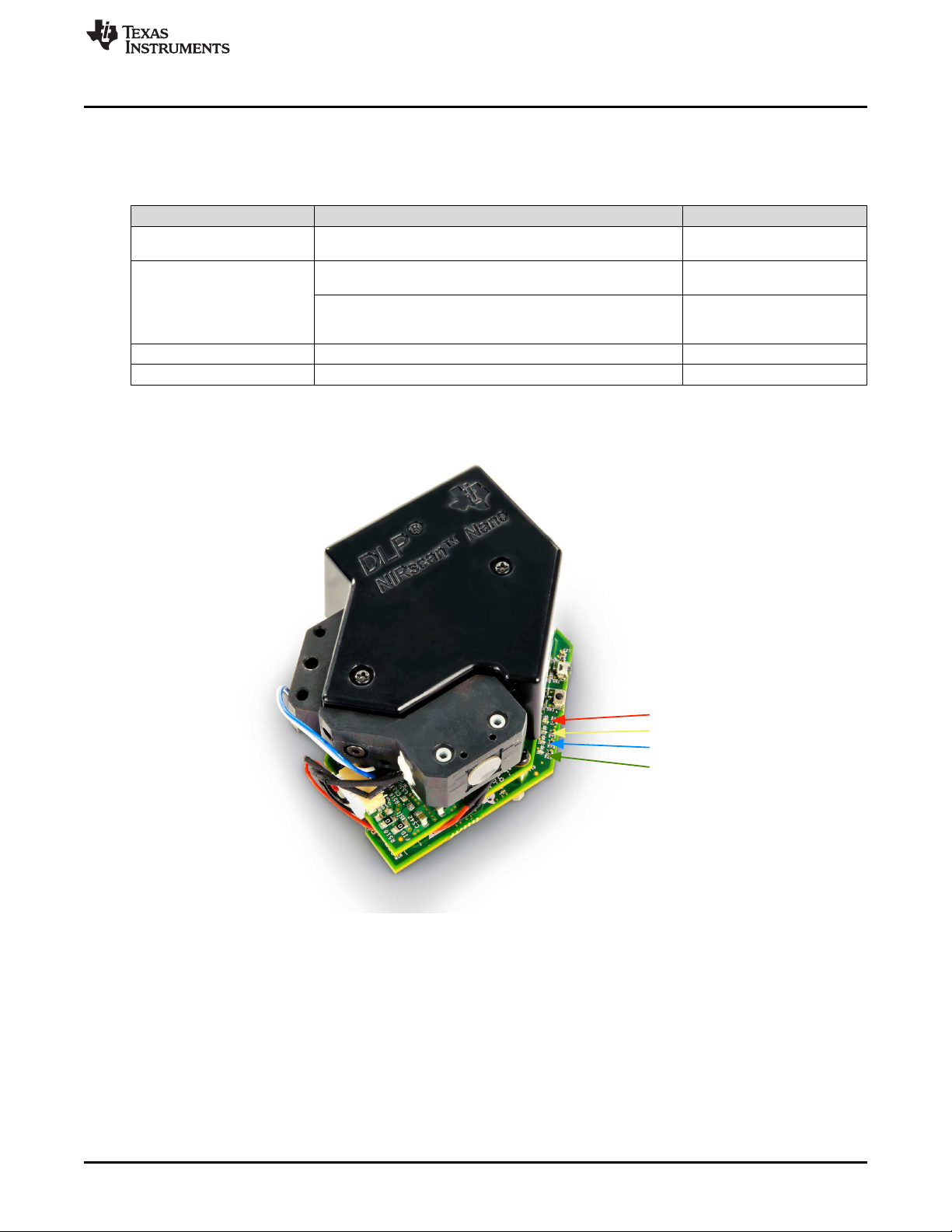
1.2.3 Connections
Table 1-3 lists the DLP NIRscan Nano connectors with its locations shown in Figure 1-4 and Figure 1-5.
BOARD SCHEMATIC LABEL DESCRIPTION
Microcontroller board
DLP controller board
www.ti.com
Table 1-3. DLP NIRscan Nano Connectors
J1
J2
J3 external device. UART4 is used as Tiva's console output for debugging
J4
J6 Lithium-Ion or Lithium-Polymer battery connection
J7 Battery thermistor connection
J500 this connector requires to removal of the Microcontroller and DLP
J501 Lamp photodetector connector
J503 Lamp power connector
Micro-USB connector: Provides power and PC connectivity with HID
commands
Detector board interface: Provides Tiva's SSI1 connection to ADS1255
and Tiva's I2C7 to TMP006
Expansion connector: Provides TIva's UART4 or SSI0 interface to
information
JTAG connector: ARM Cortex 10-pin emulation (XDS100, XDS200, or
XDS560) connection
Trigger connector. This connector is covered by the top cover. Access to
controller boards from the optical engine
14
Figure 1-4. DLP NIRscan Connectors (Rear View)
DLP NIRscan Nano Overview DLPU030B–June 2015–Revised July 2015
Copyright © 2015, Texas Instruments Incorporated
Submit Documentation Feedback
Page 15
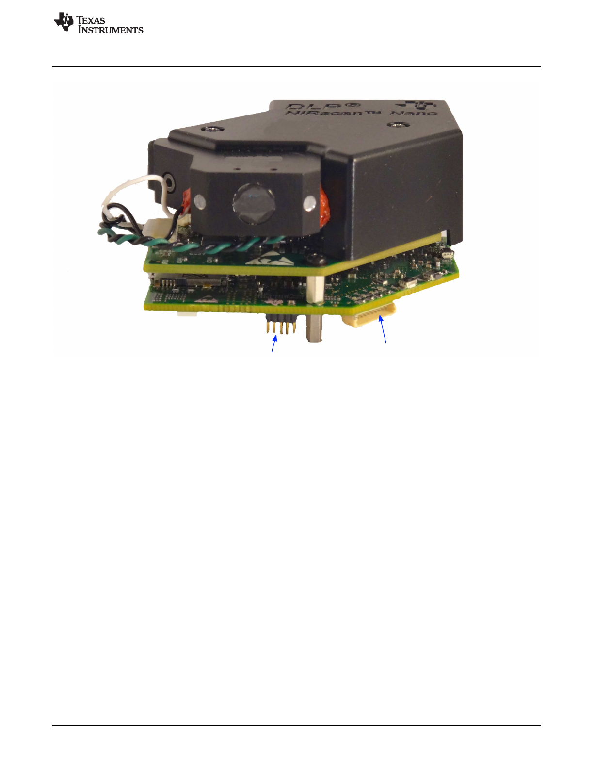
Expansion
JTAG
www.ti.com
What is the DLP NIRscan Nano EVM?
Figure 1-5. DLP NIRscan Connectors (Front View)
DLPU030B–June 2015–Revised July 2015 DLP NIRscan Nano Overview
Submit Documentation Feedback
Copyright © 2015, Texas Instruments Incorporated
15
Page 16
Reset Button
Wake Button
Scan / Bluetooth
Button
Sample
Window
What is the DLP NIRscan Nano EVM?
1.2.3.1 Buttons
The DLP NIRscan Nano EVM includes three buttons:
• Wake button:
– When the system is in standby, pressing the Wake button will wake the system from hibernation
mode.
– Upon wake up, the green LED will pulse on and off.
• Scan/Bluetooth button:
– When pressed and released, the system performs a scan. During a scan, the yellow LED is
illuminated and the lamps will turn on for the duration of the scan.
– When pressed, held for more than 3 seconds, and then released, the Bluetooth subsystem powers
up and advertises a connection. While a Bluetooth Low Energy connection is advertised, the blue
LED will turn on. When a Bluetooth Low Energy connection is active, the blue LED will pulse off
and on. The pulsing may coincide with the green LED or may pulse opposite to the green LED
pulses.
• Reset button:
– Pressing the Reset button will initiate a hardware reset of the NIRscan Nano system.
www.ti.com
16
Figure 1-6. DLP NIRscan Nano Button Locations
DLP NIRscan Nano Overview DLPU030B–June 2015–Revised July 2015
Copyright © 2015, Texas Instruments Incorporated
Submit Documentation Feedback
Page 17
Power On LED
Scan LED
Bluetooth LED
Battery Charging LED
www.ti.com
1.2.3.1.1 LEDs
The DLP NIRscan Nano EVM includes four LEDs to indicate activity as shown in Table 1-4.
What is the DLP NIRscan Nano EVM?
Table 1-4. DLP NIRscan Nano LED Indicators
LED CONDITION DESCRIPTION
Green Pulse on and off, once a second
ON
Blue
Pulse on and off, once a second connection has been
Yellow ON Scan is being performed
Red ON System is charging a battery
Indicates system is powered
and active
Bluetooth circuits are active
and advertizing
Bluetooth Low Energy
established
Figure 1-7. DLP NIRscan Nano LED Locations
DLPU030B–June 2015–Revised July 2015 DLP NIRscan Nano Overview
Submit Documentation Feedback
Copyright © 2015, Texas Instruments Incorporated
17
Page 18
2.1 Operating Modes
The DLP NIRscan Nano supports the following modes of operation:
• USB connection: A Windows®application with a graphical user interface (GUI), running on a PC with
the Windows 7 or 8 operating system, controls the system. Control includes scan initiation, parameter
settings, and data download. The PC GUI displays the intensity or absorbance of the scan. The PC
powers the NIRscan Nano through the USB cable.
• Bluetooth connection: An iOS app (available from KS Technologies through the Apple®App StoreSM)
running on an iPhone®or iPad®with iOS 7.1 or later operating system controls the system. Control
includes scan initiation, parameter settings, and downloading data. The iOS app displays the intensity
or absorbance of the scan. A USB cable or optional battery powers the NIRscan Nano.
• Standalone: The NIRscan Nano can be preconfigured through the PC GUI or Bluetooth iOS app.
Scans are invoked through the Scan button and data is stored on the on-board SDRAM or microSD
card. The stored scan data can be later downloaded to a host PC through USB or Bluetooth
connection.
Chapter 2
DLPU030B–June 2015–Revised July 2015
Getting Started
2.1.1 USB Connection
When a USB cable is inserted into the DLP NIRscan NanoJ1 micro-USB connector (see Figure 1-4), the
system powers up from the PC's USB VBUS 5-V supply, and the power-on LED pulses to indicate the
system is operational and ready for a command. The PC GUI will show as connected after the DLP
NIRscan Nano enumerates through USB.
2.1.1.1 NIRscan Nano GUI
The DLP NIRscan Nano software includes a QT-based PC GUI called NIRscanNanoGUI.exe. This GUI
requires the following dynamic link libraries (DLLs) to reside in the same directory as the executable file:
• hidapi.dll — USB human interface device (HID) class communication driver
• icudt53.dll — Qt Creator v5.3 Unicode library
• icuin53.dll — Qt Creator v5.3 Unicode library
• icuuc53.dll — Qt Creator v5.3 Unicode library
• libgcc_sdw2-1.dll — GCC library
• libstdc++6.dll — Standard C++ library
• libwinpthread-1.dll — Pthreads for Windows library
• Qt5Core.dll — Qt Core class library
• Qt5Gui.dll — Qt Graphical User Interface class library
• Qt5Svg.dll — Qt Scalable vector graphics class library
• Qt5Widgets.dll — Qt Widgets class library
• platforms/qwindows.dll — Platform plugin for Windows applications
• lmdfu.dll — Tiva USB device firmware upgrade
• lmusb.dll — Tiva USB driver
The Qt windeployqt executable will list all the DLLs necessary by a Qt application.
18
Getting Started DLPU030B–June 2015–Revised July 2015
Copyright © 2015, Texas Instruments Incorporated
Submit Documentation Feedback
Page 19

www.ti.com
2.1.2 Bluetooth Connection
To connect to the DLP NIRscan Nano, the Bluetooth circuits must first be powered. The following steps
activate the Bluetooth circuits:
1. Press the Scan/Bluetooth button and hold it for more than 3 seconds to power the Bluetooth circuits.
2. After the Bluetooth circuits are powered and active, the blue LED turns on and the DLP NIRscan Nano
advertises its presence through Bluetooth.
3. Run the iOS App and click the Scan button at the top-right of the screen. This will establish a
connection with the DLP NIRscan Nano. The Bluetooth icon on the top-right of the screen will flash.
4. After the DLP NIRscan Nano establishes connection, the blue LED will pulse to indicate that the
connection was successful.
Operating Modes
DLPU030B–June 2015–Revised July 2015 Getting Started
Submit Documentation Feedback
Copyright © 2015, Texas Instruments Incorporated
19
Page 20
3.1 NIRscan Nano GUI
Upon execution of the NIRscanNanoGUI.exe, the software checks for the DLP NIRscan Nano EVM
enumerating through USB and displays the information screen shown in Figure 3-1. The GUI is divided
into two sections:
• The top section displays the connected state of the DLP NIRscan Nano EVM on the top-right side. It
also has four buttons:
– Information: Changes the bottom portion of the GUI to display version information, and links to
online resources.
– Scan: Changes the bottom portion of the GUI to display spectrum plots and controls for scan
configurations and parameters.
– Utilities: Changes the bottom portion of the GUI to display sensor information and to synchronize
data and time with PC, ADC PGA settings, and firmware upgrades.
– Connected Status Button: Once a DLP NIRscan Nano enumerates, the icon in the connected status
button will change from a gray indicator light with a "Not Connected" message to a green indicator
light with a "Connected" message. Pressing this button has no effect. Disconnecting the DLP
NIRscan Nano, powering down the device, or resetting the DLP NIRscan Nano will toggle the state
of this button.
• The lower section displays information related to the three main operational modes: information, scan,
and utilities.
Chapter 3
DLPU030B–June 2015–Revised July 2015
Operating the DLP NIRscan Nano EVM
20
Operating the DLP NIRscan Nano EVM DLPU030B–June 2015–Revised July 2015
Copyright © 2015, Texas Instruments Incorporated
Submit Documentation Feedback
Page 21
www.ti.com
NIRscan Nano GUI
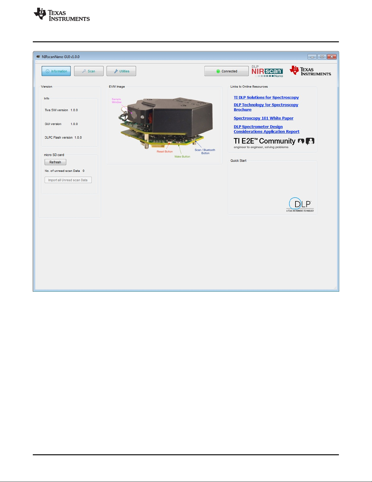
Figure 3-1. DLP NIRscanNano GUI Information Screen
The information screen displays:
• Version information, including the version number of the Tiva and DLPC150 firmware, as well as the
GUI software version number.
• EVM image, which displays the locations of the buttons and their functionality.
• Links to online resources, including Texas Instruments DLP brochures, white papers, and application
notes on spectroscopy with DLP technology. For support, users can search TI's E2E Community. The
TI E2E icon includes a link to direct users to the Texas Instruments DLP E2E forums.
• Presence of microSD card by clicking the Refresh button. Under this button, the "Import all Unread
scan Data" buttons transfer any scan data residing on the microSD card to the PC.
DLPU030B–June 2015–Revised July 2015 Operating the DLP NIRscan Nano EVM
Submit Documentation Feedback
Copyright © 2015, Texas Instruments Incorporated
21
Page 22
NIRscan Nano GUI
3.1.1 Scanning a Sample
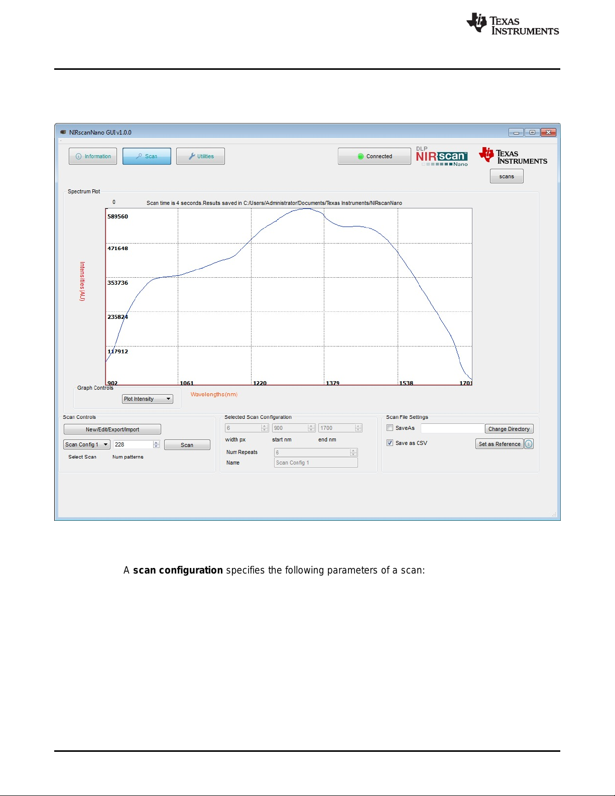
The Scan button at the top of the NIRscan Nano GUI displays spectrum plots and controls scan
configurations and parameters, as shown in Figure 3-2.
www.ti.com
22
Figure 3-2. DLP NIRscanNano GUI Scan Screen
A scan configuration must be created to scan a sample. (See Figure 3-3 for the Scan Configuration dialog
screen.) A scan configuration specifies the following parameters of a scan:
• Wavelength range: Start and End wavelengths (in nm) or spectral range of interest for the scan. The
minimum wavelength is 900 nm and the maximum wavelength is 1700 nm.
• Width in nm: This number must be greater than 8 nm and corresponds to the desired smallest
wavelength content that you want to resolve in a scan. The DLP NIRscan Nano optical resolution is 10
nm, so values less than 10 nm result in lower signal intensity.
• Number of patterns: This number defines how many wavelength points are captured across the
defined spectral range. Depending on the previous setting, the GUI computes the maximum number of
patterns and indicates them as the "Max Limit."
• Number of scans to average: This is the repeated back-to-back scans that are averaged together.
Typical scan configuration parameters for four type of scans that resolve wavelength content in 20-, 15-,
10-, and 8-nm, are shown in Table 3-1.
Operating the DLP NIRscan Nano EVM DLPU030B–June 2015–Revised July 2015
Copyright © 2015, Texas Instruments Incorporated
Submit Documentation Feedback
Page 23

www.ti.com
NIRscan Nano GUI
Table 3-1. Typical Scan Configuration Parameters
SCAN CONFIGURATION 20-nm 15-nm
PARAMETERS CONTENT CONTENT
Wavelength range 900 to 1700 nm 900 to 1700 nm 900 to 1700 nm 900 to 1700 nm 900 to 1700 nm
Width in nm 20 15 10 8 8
Number of patterns 80 108 160 225 248
Oversampling 2 2 2 2.25 2.48
Number of scans to average 18 12 8 to 9 6 5
10-nm CONTENT 8-nm CONTENT
The following steps create a scan configuration:
1. Click the "New/Edit/Export/Import" button in the Scan control box to invoke the Scan Configuration
dialog box.
2. The Scan Configuration dialog box shown in Figure 3-3 has three sections:
• The top-left section displays previous scan configurations saved to the PC.
• The top-right section displays the scan configurations saved on the DLP NIRscan Nano EVM.
• The bottom section displays the scan configuration parameters of the selected PC or DLP NIRscan
Nano EVM stored scan configuration.
3. Click the New button in the top-left section of the Scan Configuration dialog. Then, type the desired
spectral range between 900 and 1700 nm.
4. Select the width in nm that corresponds to the smallest wavelength content that you want to resolve.
5. Enter the desired number of wavelength points captured across the spectral range.
6. Enter the number of scans to average for corresponding back-to-back scans to average.
7. Enter a configuration name and click Save.
8. Close the Scan Configuration dialog by clicking OK.
DLPU030B–June 2015–Revised July 2015 Operating the DLP NIRscan Nano EVM
Submit Documentation Feedback
Copyright © 2015, Texas Instruments Incorporated
23
Page 24

NIRscan Nano GUI
www.ti.com
24
Figure 3-3. DLP NIRscanNano GUI Scan Configuration Dialog
Operating the DLP NIRscan Nano EVM DLPU030B–June 2015–Revised July 2015
Copyright © 2015, Texas Instruments Incorporated
Submit Documentation Feedback
Page 25

www.ti.com
After a scan configuration is defined, it appears under the Select Scan drop-down menu, as shown in
Figure 3-4.
NIRscan Nano GUI
Figure 3-4. DLP NIRscan Nano GUI Scan Select Menu
DLPU030B–June 2015–Revised July 2015 Operating the DLP NIRscan Nano EVM
Submit Documentation Feedback
Copyright © 2015, Texas Instruments Incorporated
25
Page 26

NIRscan Nano GUI
After a scan configuration is selected with the drop-down, define a reference by scanning a reflective
reference standard. Then, click the Set as Reference button. After these steps, scanning any sample will
allow the plot of absorbance as shown in Figure 3-5.
www.ti.com
26
Figure 3-5. Absorbance Spectrum of Aspirin
Operating the DLP NIRscan Nano EVM DLPU030B–June 2015–Revised July 2015
Copyright © 2015, Texas Instruments Incorporated
Submit Documentation Feedback
Page 27

www.ti.com
3.1.2 Displaying Previous Scans
To display previous scans, click the Scans button under the Texas Instruments logo. A sub-window will
pop up displaying the previous scans stored in the PC. The files are stored with the name of the scan
configuration appended with the date and time of the scan. To plot a file as shown in Figure 3-6, select
one of the files and click the Display Spectrum button. Click the Hide button to hide this subwindow.
NIRscan Nano GUI
Figure 3-6. Displaying Previous Scans
DLPU030B–June 2015–Revised July 2015 Operating the DLP NIRscan Nano EVM
Submit Documentation Feedback
Copyright © 2015, Texas Instruments Incorporated
27
Page 28

NIRscan Nano GUI
3.1.3 Transferring Scans Stored in microSD Card
Whenever scans are taken by pressing the Scan button on the microprocessor board, the scans are
stored on microSD card, if one is present. To transfer the stored scan on microSD:
• On the Information Tab, under microSD card, click the Refresh button.
• This will read all the scans stored on the microSD card, and will report the number of scans detected
after "No. of unread scan Data", as shown in Figure 3-7.
• On the Scan tab, click the Scans button in the upper-right corner to display the previous scans. Scans
transferred from the microSD card will be listed with filenames starting with "scan" followed by a four
digit number, as shown in Figure 3-8.
www.ti.com
28
Figure 3-7. Number of Scans Detected on microSD Card
Operating the DLP NIRscan Nano EVM DLPU030B–June 2015–Revised July 2015
Copyright © 2015, Texas Instruments Incorporated
Submit Documentation Feedback
Page 29

www.ti.com
NIRscan Nano GUI
Figure 3-8. 3 Scans Transferred from microSD Card
3.1.4 Utilities
The DLP NIRscanNano GUI includes a Utilities screen, as shown in Figure 3-9, that displays:
• Sensor data:
– Battery voltage, if a Lithium-Ion or Lithium polymer single cell battery is connected to J6 connector.
– Ambient temperature read by the TMP006 in the Detector Board.
– Detector temperature read by the TMP006 in the Detector Board.
– Ambient humidity read by the HDC1000 in the Microcontroller Board.
– HDC temperature read by the HDC1000 in the Microcontroller Board.
– Tiva internal temperature read by the Tiva internal sensor in the microcontroller board.
• Tiva's hibernation module date and time. Pressing the "Sync Data/Time" button will read the PC's date
and time and store it in the Tiva hibernation module's date and time registers.
• DLPC150 Firmware update tool.
– To update the DLPC150 firmware, click the Browse button to search for the DLPC150 firmware file
(for example, C:\ti\DLPR150PROM_1.0.0.img).
– Then, click the Update DLPC150 Firmware button. The firmware will be flashed to the board while
DLPU030B–June 2015–Revised July 2015 Operating the DLP NIRscan Nano EVM
Submit Documentation Feedback
Copyright © 2015, Texas Instruments Incorporated
29
Page 30

NIRscan Nano GUI
the progress bar indicates the update process.
• Tiva Firmware update tool.
– To update the Tiva firmware, click the Browse button to search for the Tiva firmware file (for
example, C:\ti\DLPNIRscanNanoSoftware_1.0.0\Binaries\NIRscanNano.bin).
– Then, click the Update TIVA Firmware button. The firmware will be flashed on the Tiva internal
Flash while the progress bar indicates the update process.
• Detector board's ADS1255 PGA setting.
www.ti.com
30
Figure 3-9. DLP NIRscan Nano GUI Uitlities Screen
Operating the DLP NIRscan Nano EVM DLPU030B–June 2015–Revised July 2015
Copyright © 2015, Texas Instruments Incorporated
Submit Documentation Feedback
Page 31

4.1 External Power Supply Requirements
The DLP NIRscan Nano is powered from either a battery or a USB cable. The power requirements are:
• USB Cable:
– Voltage: 4.75 to 5.25 V
– Current Maximum: 560 mA when operating and 1 A when charging
– Cable: 3 ft, USB A male to micro-USB B male (cable not included)
– Digi-Key Part Number: Q853-ND
– Manufacturer: Qualtek
– Part Number: 3025010-03
• Battery: (Not Included)
– Single-Cell Lithium-Polymer UL certified battery
• Voltage: 3.7 V
• Capacity: 1700 mA
• Manufacturer: Tenergy
• Part Number: 103450
Chapter 4
DLPU030B–June 2015–Revised July 2015
DLP NIRscan Nano Hardware
NOTE: Only connect Tenergy 103450 Lithium Polymer UL certified battery or equivalent UL certified
battery that meets: maximum charge current of 1A or more, maximum charging voltage of
4.23V or higher, battery over voltage protection at 4.305V or higher, and battery under
voltage lockout at 2.5V or less.
If a battery is connected to the NIRscan Nano, a thermistor is required to safely charge the battery and
monitor its temperature. The battery thermistor requirements are:
• Battery Thermistor: (Not Included)
– 10-kΩ NTC thermistor
• Manufacturer: Murata
• Part number: NXRT15XH103FA1B040
• Digi-Key part number: 490-7167-ND
Figure 4-1 shows a block diagram of the power circuits. The main power input is the external battery and
USB connector. The bq24250 includes a single-cell battery charger and a highly efficient DC-DC converter
to regulate the system voltage at 3.52 V. With an optional thermistor, the bq24250 monitors the
temperature of the battery during charging. Note that a thermistor is required to charge the battery. The
battery charger is set to supply up to a 1-A current during charging.
The rest of the devices regulate power to the subsystem as follows:
• The DLPA2005 in the DLP controller board regulates the power to the DLP2010NIR and DLPC150.
• The TPS82671 in the microcontroller board regulates the 1.8-V supply used by the Bluetooth
subsystem CC2564MODN. To conserve power, a TPS22904 load switch turns off the 1.8-V supply to
the Bluetooth subsystem when not in used.
• The TPS630636 in the microcontroller board supplies the main 3.3 V for the microprocessor and
interface inputs and outputs to DLPC150, CC2564MODN, and Tiva microprocessor.
DLPU030B–June 2015–Revised July 2015 DLP NIRscan Nano Hardware
Submit Documentation Feedback
Copyright © 2015, Texas Instruments Incorporated
31
Page 32

EN logic
DLPA2005
VCORE
LS_OUT
VRST
VINC
VINL
VINR
DLPC150
VDD (252.9 mA)
VDDLP12
VCC_FLSH (1.0 mA)
VDD_PLL
VCC18 (12.62 mA)
VCC_INTF (1.5 mA)
RESETZ
P1P1V
TPS82671
(600 mA)
VOUT1
VIN
PROJ_ON
DLP2010NIR
VDDI (9.4mA)
VOFFSET (1.7 mA)
VDD (34.7mA)
VRESET (2 mA)
VBIAS (0.4 mA)
18V
-14V
P1P8V_SW
VINM
VINA
VBIAS
LS_IN
VOFS
VDD_PLLM (6 mA)
VDD_PLLD (6 mA)
PARKZ
RESETZ
INTZ
10V
P1P8V
TM4C129
VDD (117 mA)
VDDC
VDDA
VBAT
TPS63036
(500 mA)
VOUT1VIN
EN
P3P3V
TPS81256
(400 mA)
VOUT1
VIN
EN
ADS1255
OPA2376
DVDD (2 mA)
AVDD (50 mA)
VCC (1 mA)
P5P0V
V-
REF5025
OPA350
VCC (8.5 mA)
VOUT1
VIN (1.2 mA)
V+
CC2564MODN
VDD_IO (1 mA)
VDD_IN (41.2 mA)
EN
BQ24250
BAT
IN
SYS
3.53 - 4.2V
VLED
SW4
LDO
TS
BAT
Conn
BAT +
TEMP
BAT -
STAT
VDPM
(4.36V)
ILM (1A)
150
ISET (1A)
249
1.5K
TPS386596
(Reset Sup)
RESETZ
RESETZ
VIN
SENSE1
SENSE2
SENSE4
MRZ
28.7K
10K
95.3K
10K
SENSE3
RESETZ
100K
2.5uF
Tiva
PJ7
EN = SYSPWR (~PROJ _ON + ~RESETz + INTz)
EN
logic
EN
logic
RESETz
INTz
SYSPWR
EN
PROJ_ON
TPS22904
VOUT1VIN
EN
Tiva
PB2
P1P8V_BT
Emergency Shutdown Logic to allow
sufficient time for DLPA2005
to issue a Fast Park
PROJ_ONTiva PJ7
LS
charging
274k
107k
TPS81256
VOUT1VIN
EN
PROJ_ON
PROJ_ON
LS
OPA567
VCC (300 mA)
V+
Tiva PD2
LS
EN
OUT
0.1
INA213
OUT
IN-
IN+
V-
V+
Power Management
Legend
DLP chipset
DLP
Analog
External Power Supply Requirements
• The TPS81256 in the microcontroller board regulates the 5-V supply of the analog-to-digital converter
(ADS1255), transimpedance amplifiers circuits (OPA350 and OPA2276), and 2.5-V reference voltage
(REF5025) used in the detector board.
• A second TPS81256 in the DLP controller board regulates the 5-V supply for the lamp driver (OPA567
and INA213). The lamp driver drives two parallel lamps at 5 V and 280 mA. Each lamp is rated to a
maximum 140 mA at 5 V.
• The TPS386596 serves as reset supervisor to hold the system in reset whiles all the supplies reach
operational conditions. An external reset button issues a reset when the system has reached
operational conditions.
For detailed connections of these devices, refer to the DLP NIRscan Nano schematics.
www.ti.com
32
Figure 4-2 shows the Tiva connections to the components on the microprocessor board and detector
board. The Tiva uses a 16-MHz external crystal as input to its on-board PLL to run the Tiva system at 120
MHz. A 32-kHz crystal supplies the clock to the Tiva's hibernation module and Bluetooth circuits. An
external 32MB of SDRAM stores the patterns that are streamed to the DLPC150 through the Tiva's LCD
interface. Tiva communicates to the HDC1000 and TMP006 sensors through its I2C6 and I2C7
peripherals. Both sensors generate a DRDY signal when a new value is available. This DRDY signals
interrupt Tiva when a new value is available through PP7 for HDC1000 and PP6 for TMP006. Tiva's
UART3 communicates with the CC2564MODN for Bluetooth transfers. The UART3 defaults to a 115200
baud transfer rate. Tiva's PH5 enables the Bluetooth circuits. Tiva interfaces to the microSD card through
DLP NIRscan Nano Hardware DLPU030B–June 2015–Revised July 2015
Figure 4-1. DLP NIRscan Nano Power Block Diagram
Copyright © 2015, Texas Instruments Incorporated
Submit Documentation Feedback
Page 33

TM4C1297
OSC0
OSC1
32.768KHz
16MHz
PB1/USB0VBUS
PB0/USB0ID
PL6/USBDP
PL7/USB0DM
USB
PF3/SSI3CLK
PF1/SSI3XDAT0
PF0/SSI3XDAT1
PF2/SSI3FSS
PQ4 (I)
microSD
CC2564MODN
BT_ANT
HCI_CTS
HCI_RX
HCI_TX
HCI_RTS
LS
PP4/U3RTS
PJ1/U3TX
PJ0/U3RX
PP5/U3CTS
SLOW_CLK_IN
PP3/RTCCLK
LS
LS
PH5 (O)
nSUTD
CLK
DIN
DOUT
CS
CARD_DET
PB5/SSI1CLK
PE4/SSI1XDAT0 (TX)
PE5/SSI1XDAT1 (RX)
PB4/SSI1FSS
PH6 (O)
PP2 (I)
ADS1255
SCLK
DIN
DOUT
CSZ
SYNC
DRDY
USB0_VBUS
USB_ID
USB_DP
USB_DM
BQ24250
EN1
EN2
CEZ
PQ1 (O)
PQ0 (O)
PQ2 (O)
PA0/I2C9SCL
PA1/I2C9SDA
SCL
SDA
PB6/I2C6SCL
PB7/I2C6SDA
PP7 (I)
HDC1000
SCL
SDA
DRDY
PD0/I2C7SCL
PD1/I2C7SDA
PP6 (I)
TMP006
PQ5 (I)INT
SCL
SDA
DRDRY
AS4C16M16
PK5/EPI0S31
PN3/EPI0S30
PN2/EPI0S29
PB3/EPI0S28
PL3/EPI0S19
PL2/EPI0S18
PL1/EPI0S17
PL0/EPI0S16
PM0/EPI0S15
PM1/EPI0S14
PM2/EPI0S13
PM3/EPI0S12
PG0/EPI0S11
PG1/EPI0S10
PA7/EPI0S9
PA6/EPI0S8
PC4/EPI0S7
PC5/EPI0S6
PC6/EPI0S5
PC7/EPI0S4
PH3/EPI0S3
PH2/EPI0S2
PH1/EPI0S1
PH0/EPI0S0
CLK
CKE
CSz
WEz
RASz
CASz
DQMH
DQML
D15
BA1/D14
BA0/D13
A12/D12
A11/D11
A10/D10
A9/D9
A8/D8
A7/D7
A6/D6
A5/D5
A4/D4
A3/D3
A2/D2
A1/D1
A0/D0
Power
JTAG Header
PC0/TCK
PC1/TMS
PC2/TDI
PC3/TDO
RESETZ
PF5 (O)
PH7 (O)
PL4 (O)
WAKEz (I)
PQ3 (I)
10K
PD4/AIN7
PD5 (O)
Battery Monitor
BAT_V_SW
SENSE_EN
Bluetooth
Scan
Scan/BT
Wake
Reset
Expansion Header
PA2/SSI0CLK/U4RX
PA3/SSI0FSS/U4TX
PA4/SSI0DAT0
PA5/SSI0DAT1
PK2/U4RTS
PK3/U4CTS
Charging
STAT
www.ti.com
SSI3 in SPI mode. Tiva's SSI1 interfaces to the ADS1255. The ADS1255 also generates a DRDY signal
when conversion is completed interrupting the Tiva processor through PP2. Tiva generates a
synchronization signal to the ADS1255 through PH6 to start an ADC conversion when a pattern is
displayed by the DLP2010NIR. To monitor the battery charger bq24250, PQ5 serves as a Tiva interrupt
and commands are sent through I2C9. PQ0, PQ1, and PQ2 allow Tiva to override default bq24250
parameters. The Wake and Scan buttons are connected to Tiva's WAKE and PQ3 pins. To measure
battery voltage, TIva enables an analog MOSFET switch with PD5 to connect the battery to Tiva's ADC7
and perform a voltage measurement. An expansion headers supports a combination of Tiva SSI0 and
UART4 pins. PF5, PH7, PL4 controls the green, blue, and yellow LED, respectively.
External Power Supply Requirements
Figure 4-2. DLP NIRscan Nano Tiva Connections
DLPU030B–June 2015–Revised July 2015 DLP NIRscan Nano Hardware
Submit Documentation Feedback
Copyright © 2015, Texas Instruments Incorporated
33
Page 34

DLPC150
DATEN_CMD
PCLK
VSYNC_WE
HSYNC_CS
PDATA3
PDATA4
PDATA5
PDATA6
PDATA7
PDATA10
PDATA11
PDATA12
PDATA13
PDATA14
PDATA15
PDATA19
PDATA20
PDATA21
PDATA22
PDATA23
PDATA2
PDATA18
PDATA1
PDATA9
PDATA17
PDATA0
PDATA8
PDATA16
DLPA2005
SPI_CSZ
SPI_DIN
SPI_CLK
SPI_DOUT
RESETZ
SENS1
GPIO_3 (CS)
GPIO_2 (DOUT)
GPIO_1 (CLK)
GPIO_0 (DIN)
RESETZ
PARKZ
INTZ
0.2” TRP
VDDI
VOFFSET
VDD
VRESET
VBIAS
LS_OUT
VRST
VBIAS
VOFS
DMD Control
DMD Sub-LVDS
DMD Control
DMD Sub-LVDS
SPI0
SPI Flash
SPI_CLK
SPI_RX
SPI_TX
SPI_CS
TM4C1297
PJ6/LCDAC
PR0/LCDCP
PR1/LCDFP
PR2/LCDLP
PR4/LCDDATA00
PR5/LCDDATA01
PF7/LCDDATA02
PR3/LCDDATA03
PR6/LCDDATA04
PR7/LCDDATA05
PS4/LCDDATA06
PS5/LCDDATA07
PS6/LCDDATA08
PS7/LCDDATA09
PT0/LCDDATA10
PT1/LCDDATA11
PN7/LCDDATA12
PN6/LCDDATA13
PJ2/LCDDATA14
PJ3/LCDDATA15
PJ4/LCDDATA16
PJ5/LCDDATA17
PT2/LCDDATA18
PT3/LCDDATA19
PS0/LCDDATA20
PS1/LCDDATA21
PS2/LCDDATA22
PS3/LCDDATA23
PG7/SSI2CLK
PG5/SSI2XDAT0 (TX)
PG4/SSI2XDAT1 (RX)
PG6/SSI2FSS
SN74LVC2G125
SN74LVC1G125
PD2/I2C2SCL
PG3/I2C2SDA
IIC0_SCL
IIC0_SDA
LED_SEL
LED_SEL
PWM_IN
CMP_OUT
CMP_PWM
CMP_OUT
GPIO10/RC_CHARGE
PP0 (I)
PP1 (I)
PD3 (O)
TRIG_OUT_2
TRIG_OUT_!
TRIG_IN_1
Photodiode
LS
PJ7_O
PROJ_ON
LS
PLL_REFCLK
24MHz
SENS2
PROJ_ON
RESETZ
HOST_IRQ
PQ7 (I)
RESETZ
LS
PQ6 (I)
Logic
PE0 (O)
PE1 (O)
PD2/I2C8SCL
OPA567
EN
OUT
External Power Supply Requirements
Figure 4-3 shows the Tiva connections to the DLPC150 controller board. Tiva powers up the DLP
subsystem through PJ7. The TIva's LCD interface is connected to the DLPC150 Parallel Port interface.
Through this interface 24 patterns are transmitted per frame. DLPC150 sends two interrupts to the Tiva to
indicate when a pattern is exposed (TRIG_OUT_2) and when a new frame begins (TRIG_OUT_1). For
DLPC150 firmware updates, the Tiva con write to the DLPC150 serial flash through its SSI2 peripheral
when the DLP subsystem is powered down. Tiva's PD2 controls the lamp. A lamp photodiode is measured
by the DLPA2005 when a scan occurs. The value of the photodiode is transmitted to the DLPC150 and
then to the Tiva. This photodiode measures the lamp intensity.
www.ti.com
34
Submit Documentation Feedback
Figure 4-3. DLP NIRscan Nano Tiva Connections to DLPC150 Controller Board
DLP NIRscan Nano Hardware DLPU030B–June 2015–Revised July 2015
Copyright © 2015, Texas Instruments Incorporated
Page 35

Tiva TM4C1297
TI RTOS
TivaWare (Peripheral Library)
DLP Spectrum Library
Command Handler
USB
Driver
Scan Handler
GAP GATT
Attribute Protocol
L2CAP
HCI
HID
Protocol
FAT File
System
SDSPI
Driver
Main Application
Link Controller
RF
HCI
CC2564MODN
Bluetopia Stack
TMP006
Handler
HDC1000
Handler
5.1 Overview
The DLP NIRscan Nano's Tiva microprocessor is the system's main control processor. The Tiva handles
button presses, commands and data transfers over USB or Bluetooth, controls the DLP subsystem,
streams the patterns to select specific wavelengths, captures data from InGaAs detector, activates lamps,
and stores data in the microSD card. Due to the realtime nature of the system, the Tiva software includes
TI-RTOS that coordinates tasks while handling realtime interrupts and semaphores. Low-level drivers for
Tiva's USB, GPIO, EPI, I2C, LCD, SPI, and UART peripherals are handled by TivaWare libraries and
routines. The Bluetopia Stack handles Bluetooth communications. DLP Spectrum Library handles pattern
generation and data transformation from raw scan data to a wavelength spectrum. A command handler
interprets commands from USB or Bluetooth and starts the tasks needed to execute the commands. The
main application initializes the system and waits for commands from USB and Bluetooth. The overall
software architecture depicting these components is shown in Figure 5-1.
Chapter 5
DLPU030B–June 2015–Revised July 2015
DLP NIRscan Nano Software
Figure 5-1. DLP NIRscan Nano Software Architecture
5.1.1 TI RTOS
TI RTOS is a scalable, real-time operating system that handles scheduling and synchronization of tasks,
interrupts, includes a limited set of drivers, and provides hardware abstraction layer to ease application
software development. The TI RTOS also includes the FAT file system (FATFs) module to store data in
the microSD card. The TI RTOS drivers used by DLP NIRscan Nano are:
• I2C: driver used for Tiva communication with DLPC150, TMP006, and HDC100.
• SDSPI: SPI driver for Tiva communication with SDcard.
• USBMSCHFatFS: driver for USB mass storage class.
DLPU030B–June 2015–Revised July 2015 DLP NIRscan Nano Software
Submit Documentation Feedback
Copyright © 2015, Texas Instruments Incorporated
35
Page 36

Overview
5.1.2 TivaWare
TivaWare is a set of drivers for accessing the Tiva peripherals. DLP NIRscan Nano uses the following
TivaWare drivers:
• UART: Driver for Tiva interface with CC2564MODN
• USB: Driver for HID transfers between Tiva and PC. The USB drivers handles Tiva's USB interrupts
• SPI: Driver for Tiva interface with ADS1255
• ADC: Driver to control Tiva ADC peripheral
• GPIO: Driver to control Tiva GPIO pins
• LCD: Driver to interface Tiva with DLPC150 parallel port
5.1.3 USB Driver
USB Communication to the DLP NIRscan Nano uses the HID class. Tiva enumerates as a slave USB 2.0
high power device. Appendix G lists the commands supported through USB.
5.1.4 SDSPI Driver
To store data on the microSD card, Tiva's SSI3 peripheral communicates with the microSD card using SPI
mode (SDSPI). Tiva stores data on the microSD card using the file allocation table (FAT) file system.
5.1.5 Bluetopia Stack
The DLP NIRscan Nano wirelessly communicates using Bluetooth Low Energy (BLE) version 4.0. The
Bluetooth communication is handled by the TI Bluetopia stack and the Cc2564MODN. The TI Bluetopia
stack and CC2564MODN implement a fully certified Bluetooth 4.0 specification. The BLE wireless
communication uses two main profiles for discovery and communication with a remote host:
• GAP: Generic Access Profile for basic discovery and establishing connections.
• GATT: Generic Attribute Profile for commands and data transfer.
The DLP NIRscan Nano supports Bluetooth version 4.0 specification. When Bluetooth subsystem is
activated, the DLP NIRscan Nano broadcasts its availability while a smartphone, tablet or PC acts as an
observer. Once connected, the DLP NIRscan Nano acts as a server for the GATT profile while the
smartphone, tablet, or PC acts as a client.
The DLP NIRscan Nano Bluetooth GATT Profile supports the following services:
• Battery Service (BAS) to provide battery charge capacity.
• Device Information Service (DIS) to provide manufacturer name, model number, serial number,
hardware revision, spectrum library revision, and Tiva software revision.
• GATT General Information Service to provide temperature, humidity, status, hours of use, lamp hours,
and battery recharge cycles.
• GATT Date and Time Service to synchronize date and time information between smartphone, tablet, or
PC to the Tiva's realtime clock.
• GATT Calibration Service to provide calibration coefficients.
• GATT Scan Configuration Service to provide stored configurations and scan configuration data.
• GATT Scan Data Service to initiate scan, clear scan data, and return stored scan data.
The Tiva processor handles these profiles and uses the logical link control and adaptation protocol
(L2CAP) to pass packets through a host controller interface (HCI). The Tiva's UART3 peripheral
communicates with the CC2564MODN HCI module. The CC2564MODN transmits these packets to the
client device.
www.ti.com
36
DLP NIRscan Nano Software DLPU030B–June 2015–Revised July 2015
Copyright © 2015, Texas Instruments Incorporated
Submit Documentation Feedback
Page 37

Configuration
dlpspec_scan_read_configuration() Cast to scanConfig struct
Access properties
directly
Configuration
Buffer Size
www.ti.com
5.1.6 DLP Spectrum Library
The DLP spectrum library is a collection of C-language routines that provide the fundamental pieces to
use a DLP system in a spectroscopy application. The DLP spectrum library is resolution and host
processor independent, allowing the routines to be used with different DMD resolutions and processor
systems. The routine sources are shared by the Tiva code, the GUI code, and the iOS App. The DLP
Spectrum Library are classified into three main categories:
• Scan: Performing a column or Hadamard scan by:
– Generating the appropriate full-frame DMD patterns based on a specific scan configuration.
– Computing reflectance and absorbance data form the intensity data during a scan.
– Handling serialization and deserialization of scan configuration and scan data.
• Calibration: Calibrating a system at the factory by:
– Finding peaks from a scan of a calibrated lamp.
– Finding the full width half maximum of specific peaks data of a calibration scan.
– Computing the calibration coefficients for a system.
• Utilities: Utilities to handle:
– Conversion between DMD mirror column position to a calibrated wavelength or wave number, and
vice versa.
– Spectrum data calculations, such as: absorbance, reflectance, and spectrum comparisons.
– Matrix operations.
– Binary pattern packing.
The DLP NIRscan Nano utilizes a previously-created scan configuration (through the GUI or stored on the
NIRscan Nano) to perform a scan. This scan configuration is created on the NIRscanNanoGUI and
transferred to the system in serialized fashion. The system's Tiva processor deserializes this data and
generates a set of full-frame DMD patterns based on the scan configuration and the factory-stored
calibration data. Then, the Tiva turns on the lamps and streams the full-frame DMD patterns to perform a
scan. Tiva collects several data points for each pattern from the detector's ADC conversion. This data is
stored in a structure, and is then serialized and transferred to the PC through USB or Bluetooth. The
NIRscanNanoGUI or the iOS App deserializes this scan data, interprets it using the DLP Spectrum
Library, and plots the resulting spectrum.
Overview
5.1.7 DLP Spectrum Library Workflow
The following sections show the use of the DLP Spectrum Library workflow to read scan configuration
information, decode scan data, and compute reference, absorbance, and reflectance.
5.1.7.1 Scan Configuration Workflow
The DLP Spectrum Library routine to interpret scan configuration information is
dlpspec_scan_read_configuration(). This routine takes as input the serialized scan configuration
transferred through USB or Bluetooth and deserializes to extract all the scan configuration information.
Figure 5-2 shows the typical workflow to view configuration information. The white input box denotes USB
scan configuration data, while the blue input box denotes Bluetooth scan configuration data.
Figure 5-2. DLP Spectrum Library View Configuration Information Workflow
DLPU030B–June 2015–Revised July 2015 DLP NIRscan Nano Software
Submit Documentation Feedback
Copyright © 2015, Texas Instruments Incorporated
37
Page 38

scanResults struct
(reference)
scanResults struct
(sample scan)
client specific.
Reflectance = sample / reference
Reflectance
Plot Reflectance
Wavelength
Intensity
Intensity
Scan Results struct
(sample scan)
Reference
Calibration Data
dlpspec_scan_interpReference()
scanResults struct
(reference)
Allocate scanResults
struct pointer
Scan Data
Allocate scanResults
struct pointer
dlpspec_scan_interpret()
scanResults struct
(sample scan)
Access properties directly, could
display raw intensity if desired
Scan Data
Buffer Size
Overview
5.1.7.2 Decode Scan Workflow
The DLP Spectrum Library routine to interpret scan data is dlp_scan_interpret(). This routine takes as
input the serialized scan data transferred through USB or Bluetooth and deserializes and extracts the
intensities of each wavelength in a scan. Figure 5-3 shows the typical workflow to decode scan data. The
white input box denotes USB scan data, while the blue input box denotes Bluetooth scan data.
Figure 5-3. DLP Spectrum Library Decode Scan Results Workflow
5.1.7.3 Compute Reference Workflow
The DLP Spectrum Library routine to compute reference is dlp_scan_interpReference(). This routine
takes as input the serialized reference calibration data stored on the DLP NIRscan Nano and transmitted
through Bluetooth or the stored reference on the PC transmitted through USB and computes the reference
intensities for each wavelength in a scan. Figure 5-4 shows the typical workflow to compute the reference.
The white input box denotes USB reference data, while the blue input box denotes Bluetooth reference
calibration data.
www.ti.com
5.1.7.4 Compute and Display Reflectance Workflow
The DLP Spectrum Library computes the reflectance of a scan based on the scan intensities divided by
the reference scan. Figure 5-5 shows the typical workflow to compute the reflectance.
38
DLP NIRscan Nano Software DLPU030B–June 2015–Revised July 2015
Figure 5-4. DLP Spectrum Library Compute Reference Workflow
Figure 5-5. DLP Spectrum Library Compute and Display Reflectance Workflow
Copyright © 2015, Texas Instruments Incorporated
Submit Documentation Feedback
Page 39

client specific.
Absorbance = -log10(Reflectance)
Absorbance
scanResults struct
(reference)
scanResults struct
Plot Absorbance
Wavelength
Intensity
Intensity
www.ti.com
5.1.7.5 Compute and Display Absorbance Workflow
5.2 Software System Overview
DLPU030B–June 2015–Revised July 2015 DLP NIRscan Nano Software
Submit Documentation Feedback
Software System Overview
The DLP Spectrum Library computes the absorbance of a scan based on the negative of the logarithm
(based 10) of the reflectance. Figure 5-6 shows the typical workflow to compute the reflectance.
Figure 5-6. DLP Spectrum Library Compute and Display Absorbance
The DLP NIRscan Nano software uses a sets of tasks, hardware interrupts, and semaphores to
coordinate the efforts needed to interpret USB or Bluetooth commands, respond to button presses, scan
an object, and capture the InGaAs detector values. Figure 5-7 shows a high-level block diagram of the
software elements of the system. The DLP NIRscan Nano system includes the following hardware
interrupt handlers to respond to hardware events:
• Button Interrupt Handler: Responds to Scan/Bluetooth button presses and Wake button presses.
• Trigger Interrupt Handler: Synchronizes and keeps track of the pattern displayed during a scan. Two
interrupts from the DLPC150 (ihFrameTrigger and ihPatternTrigger) indicate when a pattern has been
displayed, when 24 patterns have completed the display, and when the DLPC150 buffer needs to be
reloaded with new patterns. This handler also captures data from the ADS1255 when a pattern is
displayed. It uses the ADS1255 DRDY signal to trigger the read of the just-converted value.
• Display Interrupt Handler: Controls the Tiva LCD peripheral and its frame buffer that resides in external
SDRAM. The frame buffer streams 24 patterns per frame to the DLPC150.
The following tasks handle specific portions of the system:
• USB driver: This task is part of the TivaWare USB driver and handles all USB HID transactions. The
data from USB transactions is passed to the command handler task to interpret and respond to a
specific set of USB commands described in Appendix G .
• Bluetooth Stack: This task handles Bluetooth communication with a mobile application through the
implementation of GATT profile in the Bluetopia Stack. Several semaphores control the operation:
– BLEStartSem: Power-up the Bluetooth circuits and initializes the Bluetooth Stack.
– BLEEndSem: Powers-down the Bluetooth circuits and gracefully closes the Bluetooth Stack.
– BLECmdRecd: Coordinates the reception and processing of GATT profiles and notifies Command
Handler of a new command to be processed.
– BLECmdCom: Handles the response to a BLE Client's read and notify requests.
– BLENotifySem: Handles the asynchronous notifications to a BLE Client's notification subscriptions.
• Command Handler: Interfaces the USB and Bluetooth tasks, interprets commands, and starts the
sensor read task and the scanning tasks.
• Scan Handler: Controls power to the subsystems necessary to perform a scan (ADS1255, Lamp,
DLPC150), manages the pattern streamed to the DLPC150, and reads sensor information during a
scan. Two semaphores control the start of the scan (scanSem) and the end of a scan (endscanSem).
• TMP Handler: Manages the temperature readings from the TMP006.
• HDC Handler: Manages humidity and temperature readings form the HDC1000.
• microSD Handler: Controls reading and writing data to the microSD card through a FAT32 file system.
A semaphore (sdSem) triggers data access to the microSD card.
Copyright © 2015, Texas Instruments Incorporated
39
Page 40

Bluetooth Client
searches for
DLP NIRscan Nano
BLE device
found?
Read advertised
packets
BLE device
found?
Does advertised packet
have local name attribute =
NIRscanNano?
Establish
connection
No
No
No
Yes
Yes
Yes
Display INT
Handler
Trigger INT
Handler
Scan
Handler
Bluetooth
Stack
Command
Handler
microSD
Handler
USB Driver
Idle
GUI
Mobile
App
HID
Packets
BLE GATT
Atrributes
ihUSB
DLPC150
ADS1255
ihDRDY
ihFrameTrigger
ihPatternTrigger
ihLCD
TMP006
HDC1000
HDC
Handler
TMP
Handler
hwiTMPDRDY
hwiHDCDRDY
tmp006Sem
hdc1000Sem
scanSem
BLEEndSem
endscanSem
sdSem
LEDs
BLEStartSem
BLENotifySem
BLECmdRecd
BLECmdComp
UART
Button INT
Handler
Buttons
Wake
Scan/BT
hwiSELButton
hwiWAKEButton
SDRAM
Interrupts
Sempahore
Tasks
Interrupt Handler
Hardware
CC2564MODN
UART
Bluetooth Client App Workflow
• Idle Task: Manages the blinking of the LED and UART console transmissions to the expansion
connector.
www.ti.com
Figure 5-7. DLP NIRscan Nano Software Block Diagram
5.3 Bluetooth Client App Workflow
The following sections describe a suggested workflow for the Bluetooth Client to connect and transfer
data.
5.3.1 Bluetooth Client Establishing a Connection
The Bluetooth Client searches for the DLP NIRscan Nano using the GAP for discovery. Once the
40
Bluetooth Client detects a DLP NIRscan Nano, the Bluetooth Client reads the DLP NIRscan Nano
advertized packets, establishing a connection. Figure 5-8 describes this process.
DLP NIRscan Nano Software DLPU030B–June 2015–Revised July 2015
Figure 5-8. Bluetooth Low Energy Connection Workflow
Copyright © 2015, Texas Instruments Incorporated
Submit Documentation Feedback
Page 41

GATT Calibration Service
enumerated?
Subscribe to
Return
Spectrum
Calibration
Coefficients
notification
Yes
Write to
Request
Spectrum
Calibration
Coefficients
DLP NIRscan
Nano returns
spectrum
calibration
coefficeints in
serialized data
format
Subscribe to
Return
Reference
Calibration
Coefficients
notification
Write to
Request
Reference
Calibration
Coefficients
DLP NIRscan
Nano returns
reference
calibration
coefficients in
serialized data
format
Subscribe to
Request
Reference
Calibration
Matrix
notification
Write to
Request
Spectrum
Calibration
Matrix
DLP NIRscan
Nano returns
reference
calibration matrix
in serialized data
format
No
www.ti.com
5.3.2 Bluetooth Client GATT Profiles
Once the Bluetooth Client establishes a connection with the DLP NIRscan Nano, the supported GATT
profile is enumerated. DLP NIRscan Nano uses standard Bluetooth Low Energy services for Device
Information (DIS) and Battery (BAS). The rest of the data transfer is through the custom GATT services
and characteristics in the following sections. In the following workflow figures, blue denotes a GATT
service characteristic, while red denotes a DLP Spectrum library routine.
5.3.2.1 Bluetooth Client GATT General Information Service
Once the GATT General Information Service is enumerated, the Bluetooth Client can prompt DLP
NIRscan Nano to read temperature and humidity values. The Bluetooth Client can set a threshold for
temperature and humidity and then subscribe to the temperature and humidity threshold notification. The
Bluetooth Client can also read a device and error status and then subscribe to the device and error status
notifications.
5.3.2.2 Bluetooth Client GATT Date and Time Service
Once the GATT Date and Time Service is enumerated, the Bluetooth Client can write the data and time
values to the DLP NIRscan Nano. It is recommended that the Bluetooth Client sets the date and time
every time a connection is established, so the scan data has the correct date and time stamp.
5.3.2.3 Bluetooth Client GATT Calibration Service
Once the GATT Calibration Service is enumerated, the Bluetooth Client can prompt DLP NIRscan Nano to
download spectrum calibration coefficients, reference calibration coefficients, and reference calibration
matrix. These parameters are unique for each DLP NIRscan Nano and are required for spectrum intensity,
reflectance, and absorbance plots. These parameters must to be downloaded whenever a new DLP
NIRscan Nano is connected to a Bluetooth Client and before a scan is performed. To download these
parameters, the Bluetooth Client must follow these steps:
• Subscribe to the notification of the characteristic UUID that returns the corresponding coefficient.
• Issue a request for the coefficient and wait for the notification to read the corresponding coefficient.
• Once a notification is received, then the Bluetooth Client reads the serialized multiple packets from
DLP NIRscan Nano.
Figure 5-9 shows the workflow for this service.
Bluetooth Client App Workflow
Figure 5-9. GATT Calibration Service Workflow
DLPU030B–June 2015–Revised July 2015 DLP NIRscan Nano Software
Submit Documentation Feedback
Copyright © 2015, Texas Instruments Incorporated
41
Page 42

GATT Scan Configuration
Service enumerated?
Read
Number of
Stored
Configurations
Yes
Subscribe to
Return Stored
Configurations
List
notification
DLP NIRscan
Nano returns the
number of stored
scan
configurations
Write to
Request Stored
Configuration
List
Subscribe to
Return Scan
Configuration
Data
notification
DLP NIRscan
Nano returns
stored
configurations
Write scan
configuration ID
to
Return Scan
Configuration
Data
Deserialize data
using DLP Spectrum
Library
dlpspec_deserialize
DLP NIRscan
Nano returns
requested scan
configuration in
serialized data
format
No
Read all stored scan
configurations?
Write to
Active Scan
Configuration
to set an active
configuration for
future scans
Yes
No
Bluetooth Client App Workflow
5.3.2.4 Bluetooth Client GATT Scan Configuration Service
Once the GATT Scan Configuration Service is enumerated, the Bluetooth Client can prompt DLP NIRscan
Nano to download stored scan configurations. These parameters must to be downloaded whenever a new
DLP NIRscan Nano is connected to a Bluetooth Client and before a scan is initiated. To read the stored
scan configuration, the Bluetooth Client must perform the following steps:
• Read the number of stored configurations.
• Subscribe to the notification of the characteristic that returns stored configuration list.
• Issue a request for stored configuration list and wait for the notification to read the stored configuration
list.
• Subscribe to the notification of the characteristic that returns scan configuration data.
• Read each scan configuration data by writing the scan configuration ID to the characteristic that
returns the scan configuration data, wait for the notification, and then read the serialized scan
configuration data returned. The DLP Spectrum Library provides a routine to interpret this serialized
data: dlpspec_deserialize. Repeat this step for each stored scan configuration.
• Set the active scan configuration by writing to the scan configuration ID to the active scan configuration
characteristic.
Figure 5-10 depicts the workflow for this service.
www.ti.com
Figure 5-10. GATT Scan Configuration Service Workflow
5.3.2.5 Bluetooth Client GATT Scan Data Service
Once the GATT Scan Data Service is enumerated, the Bluetooth Client can prompt DLP NIRscan Nano to
download stored scan data or perform a scan. To read the stored scan data, the Bluetooth Client must
perform the following steps:
• Read the number of stored scans.
• Subscribe to the notification of the characteristic that returns stored scan indices list.
42
• Issue a request to read stored configuration list, wait for the notification to read the stored configuration
list.
DLP NIRscan Nano Software DLPU030B–June 2015–Revised July 2015
Copyright © 2015, Texas Instruments Incorporated
Submit Documentation Feedback
Page 43

GATT Scan Data Service
enumerated?
Read
Number of
Stored Scans
Yes
Subscribe to
Stored Scan
Indices List
notification
DLP NIRscan
Nano returns the
list of stored
scans
Write to
Request Stored
Configuration
List
Subscribe to
Return Scan
Name
No
Read all stored scan
information?
List scans
Yes
No
Subscribe to
Return Scan
Type
notification
Subscribe to
Return Scan
Date/Time
notification
Subscribe to
Return Packet
Format Version
notification
Write to
Return Scan
Name
with parameter
scan index
Write to
Return Scan
Type
with parameter
scan index
Write to
Return Scan
Date/Time
with parameter
scan index
Write to
Return Packet
Format Version
with parameter
scan index
www.ti.com
• Subscribe to the notifications of the characteristics to return scan name, scan type, and scan date/time,
• Issue requests for scan name, scan type, scan date/time, and packet format version. Then wait for the
To perform a scan, the Bluetooth Client must perform the following steps:
• To display an existing scan:
• To initiate a scan:
• To delete stored scan data:
Figure 5-11 and Figure 5-12 show the workflow for this service.
Bluetooth Client App Workflow
and to request packet format version.
notifications to read scan name, scan type, scan date/time, and packet format version. Repeat the last
two steps for each stored scan.
– If the scan information is not available, subscribe to the notification of the characteristic to return
serialized scan data structure.
– Issue a request to read serialized scan data structure and wait for the notification to read the scan
data structure. The DLP Spectrum Library provides a routine to interpret this serialized data:
dlpspec_scan_interpret.
– Subscribe to the notification of the characteristics to start scan.
– Issue a request to start scan and wait for the notification that indicates the scan completed.
– Subscribe to the notifications of the characteristics to return scan name, scan type, and scan
date/time, and to request packet format version.
– Issue requests for scan name, scan type, scan date/time, and packet format version. Then wait for
the notifications to read scan name, scan type, scan date/time, and packet format version.
– Subscribe to the notification of the characteristic to return serialized scan data structure.
– Issue a request to read serialized scan data structure and wait for the notification to read the scan
data structure. The DLP Spectrum Library provides a routine to interpret this serialized data:
dlpspec_scan_interpret.
– Subscribe to the notification of the characteristic to clear scan.
– Issue a request to clear scan and wait for the notification that indicates the clear scan completed.
Figure 5-11. GATT Scan Data Service Workflow
DLPU030B–June 2015–Revised July 2015 DLP NIRscan Nano Software
Submit Documentation Feedback
Copyright © 2015, Texas Instruments Incorporated
43
Page 44

Yes
Subscribe to
Return
Serialized Scan
Data Structure
notification
DLP NIRscan
Nano returns
scan data
Write to
Request
Serialized Scan
Data Structure
No
Subscribe to
Start Scan
notification
Write to
Start Scan
with parameter
store scan in
microSD card
Bluetooth Client
selects a stored scan
Scan details
available?
Interpret data using DLP
Spectrum Library
dlpspec_scan_interpret
Display Spectrum
Perform a scan
Yes
Subscribe to
Return Scan
Type
notification
Subscribe to
Return Scan
Date/Time
notification
Subscribe to
Return Packet
Format Version
notification
Write to
Return Scan
Name
with parameter
scan index
Write to
Return Scan
Type
with parameter
scan index
Write to
Return Scan
Date/Time
with parameter
scan index
Write to
Return Packet
Format Version
with parameter
scan index
Erase scan from
DLP NIRscan
Nano?
Subscribe to
Clear Scan
notification
Write to
Clear Scan
with parameter
scan ID
Bluetooth Client App Workflow
www.ti.com
Figure 5-12. GATT Scan Data Service Workflow to Display an Existing Scan or Performing a New Scan
44
DLP NIRscan Nano Software DLPU030B–June 2015–Revised July 2015
Copyright © 2015, Texas Instruments Incorporated
Submit Documentation Feedback
Page 45

Connect to
NIRscan Nano
and show
Scan
Window
Delete
Stored
Scan Data
Search
Stored Scans
Support Links
and Information
Settings
Tap to display
stored scans
6.1 NanoScan iOS App
KS Technologies has developed an example iOS app that controls the DLP NIRscan Nano EVM. This app
is available for download through the Apple App Store free of charge. This app supports BLE iOS devices:
iPhone 4S or later and iPad 3 or later with iOS 7.1 or later.
After running the NanoScan iOS App, the main screen shown in Figure 6-1 lists the previous scans
performed with the NIRscan Nano EVM. To connect to a NIRscan Nano EVM, enable the Bluetooth by
pressing and holding the scan button on the EVM for more than three seconds. The blue LED will light up
to indicate that the Bluetooth circuits are powered and actively scanning. Press Scan on the top-right
corner of the iOS App to initiate a connection. The Bluetooth icon in the top-right corner of the iPhone
screen will blink as the connection is established. The NIRscan Nano EVM blue LED will pulse to indicate
that a BLE connection was established. Then, the reference and calibration data is downloaded from the
EVM. When that is completed, the Start Scan button will be activated.
Chapter 6
DLPU030B–June 2015–Revised July 2015
iOS App
Figure 6-1. NanoScan Main Screen
Pressing the Configure button in the top-right corner of the NanoScan main screen opens the
Configuration screen. The Configuration screen displays four buttons:
• Device Information: This button uses the following service:
– GATT General Information Service to request Manufacture, Model Number, Serial Number,
Hardware revision, Tiva firmware version, and Spectrum Library revision.
• Device Status: This button uses the following services:
– Battery Service to prompt for the Battery voltage. The battery is reported in percentage capacity
with 0%, 5%, 20%, 40%, 60%, and 80%.
– GATT General Information Service to request temperature, humidity, device and error status, and
also set threshold for temperature and humidity notifications.
– GATT General Information Service to report device and error status.
• Scan Configurations: This button uses the following service:
– GATT Scan Configuration Information Service to display stored scan configurations on the DLP
NIRscan Nano. The user can select which stored scan configuration will be used in future scans.
DLPU030B–June 2015–Revised July 2015 iOS App
Submit Documentation Feedback
Copyright © 2015, Texas Instruments Incorporated
45
Page 46

Return to
Main Screen
Configuration
Screen
Start a Scan
Enable to save
scan to
microSD card
Select stored
scan
configurations
Enter a filename
prefix for scan
data
Select
spectrum plot
type
NanoScan iOS App
• Stored Scan Data: This button uses the following service:
– GATT Scan Data Information Service to retrieve stored scan data from the microSD card.
Before starting a scan, the user can set a filename prefix, can elect to also save the scan data on the
microSD card, and can choose a default for future scans from the stored scan configurations, as shown in
Figure 6-2. Pressing the Start Scan button will start a scan with the selected scan configuration. Once the
scan completes, the scan data is transmitted from the NIRScan Nano and plotted. The user can choose to
plot absorbance, reflectance, or raw intensity values by tapping on the corresponding button under the plot
area.
www.ti.com
46
Figure 6-2. NanoScan Scan Screen
iOS App DLPU030B–June 2015–Revised July 2015
Copyright © 2015, Texas Instruments Incorporated
Submit Documentation Feedback
Page 47

www.ti.com
Figure 6-3 shows an example plot of absorbance for sugar.
NanoScan iOS App
Figure 6-3. NanoScan Scan Plot Screen
DLPU030B–June 2015–Revised July 2015 iOS App
Submit Documentation Feedback
Copyright © 2015, Texas Instruments Incorporated
47
Page 48

Installing the DLP NIRscan Nano Software
A.1 DLP NIRscan Nano Software Installation
The NIRscan Nano software is broken into several packages:
• DLPNIRscanNanoGUI-1.0.3-windows-installer.exe
– This is the PC program that communicates with the DLP NIRscan Nano through USB.
– This program installs the PC GUI NIRscanNanoGUI.exe under the default directory: C:\Program
Files\Texas Instruments\NIRscanNanoGUI_1.0.2\Binaries
– It also install the sources under the default directory: C:\ti\NIRscanNanoGUI\Sources
• DLPNIRscanNanoSoftware-windows-installer.exe
– This program installs the Tiva binary firmware file under the default directory:
C:\ti\DLPNIRscanNanoSoftware_1.0.0\Binaries\NIRscanNano.bin
– It also installs the sources under the default directory:
C:\ti\DLPNIRscanNanoSoftware_1.0.0\Sources
– This installer includes the TI-RTOS 2.10.1.38 and the Device Firmware Update (DFU) drivers for
Tiva. The DFU drivers allow updating the Tiva firmware through USB. If your CCS installation
already has TI-RTOS 2.10.1.38, you can skip installing this TI-RTOS package.
• DLPSpectrumLibrary-1.0.0-windows-installer.exe
– This program installs the DLP Spectrum Library. This library code is shared with the PC GUI, Tiva
software, and iOS App. The source files are under the default directory:
C:\ti\DLPSpectrumLibrary_1.0.0\src.
• DLPR150PROM-1.0.0-windows-installer.exe
– This program installs the DLPC150 firmware binary (DLPR150PROM_1.0.0.img) under the default
directory: C:\ti\DLPR150PROM_1.0.0
To install the software, run these installer executables and follow the on-screen prompts.
Appendix A
DLPU030B–June 2015–Revised July 2015
48
Installing the DLP NIRscan Nano Software DLPU030B–June 2015–Revised July 2015
Copyright © 2015, Texas Instruments Incorporated
Submit Documentation Feedback
Page 49

Required Tools to Compile Tiva Software
B.1 Tiva Tools Installation
To compile the DLP NIRscan Nano Tiva code, the following tools and software packages are required:
• Code Composer Studio (CCS) Integrated Development Environment (IDE) version 6.0.1
• TI-RTOS version 2.10.1.38
• TI ARM Compiler version 5.2.4
B.1.1 Code Composer Studio Installation
To install, follow these steps:
1. Download the latest Windows or Linux version of the CCS IDE for TM4x ARM MCU.
2. Execute the download file: c_setup_win32.exe
3. Accept the License Agreement. Click Next.
4. Select the installation location and click Next. C:\ti is the default installation location.
5. If you are running anti-virus software, you will be warned that it is recommended to temporarily disable
real-time scanning before proceeding with installation.
6. The installer will prompt for processor support. Ensure that under 32-bit ARM MCUs, Tiva C Series
Support and TI ARM Compiler are checked. Click Next.
7. Select the appropriate Debug Probes or Emulators. Tiva C Series are supported by XDS100, XDS200,
and XDS560 Debug Probes from TI, Spectrum Digital or Blackhawk.
• For more information on supported Debug Probes, visit the Tiva Tools & Software page.
• For emulation information visit the TI Emulation Wiki.
• For more information on JTAG connectors and adapters visit the XDS Target Connection Guide.
8. If prompted for apps, there is no need to select any apps.
9. After the installation is complete, update CCS by following the steps in Section B.1.2.
Appendix B
DLPU030B–June 2015–Revised July 2015
B.1.2 Updating TI-RTOS
The current Tiva Firmware build uses TI-RTOS for TivaC 2.10.1.38.
NOTE: Do not use TI-RTOS for TivaC 2.12.1.33 since the TI-RTOS drivers are different.
If you have an older installation of TI-RTOS, update TI-RTOS with the following steps after launching
Code Composer Studio:
1. Select CCS APP Center from the View Menu.
2. Type "Tiva" in the search box.
3. Update TI-RTOS for TivaC, if offered to update it. To update it, press the select button beneath the TIRTOS for TivaC icon and then click on the install software icon to the left of the search box under the
App Center logo.
TI-RTOS for TivaC 2.10.1.38 is found at this link.
DLPU030B–June 2015–Revised July 2015 Required Tools to Compile Tiva Software
Submit Documentation Feedback
Copyright © 2015, Texas Instruments Incorporated
49
Page 50

Tiva Tools Installation
B.1.2.1 Updating TI ARM Compiler
To update the TI ARM Compiler, follow these steps after launching Code Composer Studio:
1. Select CCS APP Center from the View Menu.
2. Type "compiler" in the search box.
3. Update TI ARM®Compiler, if offered to update it. To update it, press the select button beneath the TI
ARM Compiler icon and then click on the install software icon to the left of the search box under the
App Center logo.
4. Update TI ARM Compiler for TivaC.
www.ti.com
50
Required Tools to Compile Tiva Software DLPU030B–June 2015–Revised July 2015
Copyright © 2015, Texas Instruments Incorporated
Submit Documentation Feedback
Page 51

C.1 Tiva Libraries Compilation
The DLP NIRscan Nano Tiva software uses two libraries from the TivaWare package: Tiva driverlib and
Tiva usblib. It also uses a third library: DLP Spectrum Library. These libraries must be compiled under
CCS before building the DLP NIRscan Nano software.
C.1.1 Tiva driverlib Compilation
To compile the TivaWare driverlib library, follow these steps:
1. Import the driverlib library by selecting Import from the File Menu.
2. In the new Import dialog window, select CCS Projects under C/C++ folder and click Next.
3. Find the location of the TivaWare driverlib project by browsing to the directory
C:\ti\tirtos_tivac_2_10_01_38\products\TivaWare_C_Series-2.1.0.12573c\driverlib and click OK.
4. Compile this newly added driverlib project by selecting Clean from the Project Menu. Ensure that
driverlib project is checked and select "Build only the selected project" and then click OK.
Appendix C
DLPU030B–June 2015–Revised July 2015
How to Compile Tiva Source Code
C.1.2 Tiva usblib Library
To compile the TivaWare usblib library, follow these steps:
1. Import the usblib library by selecting Import from the File Menu.
2. In the new Import dialog window, select CCS Projects under C/C++ folder and click next.
3. Find the location of the TivaWare usblib project by browsing to the directory
C:\ti\tirtos_tivac_2_10_01_38\products\TivaWare_C_Series-2.1.0.12573c\usblib and then click OK.
4. Compile this newly added usblib project by select Clean from the Project Menu. Ensure that usblib
project is checked and select "Build only the selected project" and then click OK.
C.1.3 DLP Spectrum Library
The DLP Spectrum Library is a collection of C-language routines that provide the fundamental pieces to
use a DLP system in a spectroscopy application. These routines are shared by the Tiva firmware,
NIRscan Nano GUI, and iOS App. To compile the DLP Spectrum Library for Tiva firmware, follow these
steps:
1. Import the DLP Spectrum Library by selecting Import from the File Menu.
2. In the new Import dialog window, select CCS Projects under C/C++ folder and click Next.
3. Find the location of the dlpspeclib project by browsing to the install directory:
C:/ti/DLPNIRNANO_SPECLIB.
4. Compile this newly added dlpspeclib project by selecting Clean from the Project Menu. Ensure that
dlpspeclib project is checked and select "Build only the selected project" and then click OK.
C.2 Tiva Main Source
The Tiva main program sources are installed by the DLPNIRscanNanoSoftware package. This package
installs the Code Composer Studio project and source at the default directory
C:\ti\DLPNIRscanNanoSoftware_1.0.0
1. Import the Mobile Spectroscopy Tiva EVM by pulling-down the File Menu and select Import.
2. In the new Import dialog window, select CCS Projects under C/C++ folder and click Next.
DLPU030B–June 2015–Revised July 2015 How to Compile Tiva Source Code
Submit Documentation Feedback
Copyright © 2015, Texas Instruments Incorporated
51
Page 52

Project Settings
3. Find the location of the Mobile Spectroscopy Tiva EVM by browsing to the install directory of the
sources: C:\ti\DLPNIRscanNanoSoftware_1.0.0\Sources.
4. Make sure all the other libraries are compiled and imported before this step. Then, compile this newly
added Mobile Spectroscopy Tiva EVM project by selecting Clean from the Project Menu. Ensure that
dlpspeclib project is checked and select "Build only the selected project" and then click OK.
C.3 Project Settings
The compilation of the Tiva sources and libraries requires the following project settings by right clicking on:
• On Project Browser, select Mobile Spectroscopy Tiva EVM. Right-click and select "Show Build
Settings..."
• Under CCS General, select the Main tab. Ensure that the Compiler version is TI v5.2.4.
• Under CCS General, select the RTSC tab. Ensure that TI-RTOS for TivaC is set to 2.10.1.38 and
XDCtools version is 3.30.4.52_core.
• Repeat this for all libraries.
www.ti.com
52
How to Compile Tiva Source Code DLPU030B–June 2015–Revised July 2015
Copyright © 2015, Texas Instruments Incorporated
Submit Documentation Feedback
Page 53

Required Tools to Compile NIRscan Nano GUI
D.1 NIRscan Nano GUI
The NIRscan Nano GUI requires Qt Framework and tools 5.4.1 or later, MinGW compiler 4.9.1, and the
DLP Spectrum Library. The Qt Framework and tools can be downloaded from the Qt website.
D.1.1 Compiling the DLP Spectrum Library
The DLP Spectrum Library includes a batch file to compile for the PC. To compile the DLP Spectrum
Library for the NIRscan Nano GUI, follow these steps:
1. Open MS-DOS window and change to the src directory of the DLP Spectrum Library:
C:/ti/DLPNIRNANO_SPECLIB/src
2. Execute the build-lib.bat file. This batch file requires the prior installation of MinGW or a GCC toolchain
in the Windows PC with their respective binaries added to the Windows PATH environment variable.
D.1.2 Compiling NIRscan Nano GUI
After compiling the DLP Spectrum Library, compile the NIRscan Nano GUI with the following steps:
1. Run Qt Creator.
2. In Qt Creator, click on "Open Project" button. Navigate to the directory where the NIRscanNanoGUI
sources were installed. The default installation directory is C:\ti\NIRscanNanoGUI\Sources. Open the
project file NirscanNanoGUI.pro
3. A dialog window will indicate that no user settings were found. Click the Yes button.
4. Click the Projects icon on the sidebar. Ensure that the Build settings are correct and that an existing
Build directory is set.
5. From the Build menu, select Build All.
Appendix D
DLPU030B–June 2015–Revised July 2015
DLPU030B–June 2015–Revised July 2015 Required Tools to Compile NIRscan Nano GUI
Submit Documentation Feedback
Copyright © 2015, Texas Instruments Incorporated
53
Page 54

E.1 Tiva EEPROM
The Tiva TM4C129XNCZAD microcontroller includes an EEPROM with 6kB of storage. The DLP NIRscan
Nano uses this EEPROM to store the following factory information:
• DLP NIRscan Nano Serial Number: A five digit number in the format YMMSSSS, where Y represents a
one digit year of manufacturing number, MM represents a two digit month of manufacturing number,
and SSSS represents a four digit serial number
• Scan Data Index Counter: Default scan
• Calibration Coefficients Data Structure Version Number
• Calibration Coefficients Data
• Reference Calibration Data Structure Version Number
• Reference Calibration Data
• Default Scan Name
• Default Scan Configuration
• Active Scan Configuration Number and Index
• Scan Configuration Data Structure Version
• Scan Configurations
See Table E-1 for the address, size, and content of these information in Tive EEPROM.
Appendix E
DLPU030B–June 2015–Revised July 2015
Tiva EEPROM Contents
Table E-1. Tiva EEPROM
ADDRESS SIZE (BYTES) DESCRIPTION
0x0000 8 DLP NIRscan Nano Serial Number
0x0008 4 Scan Data Session Index
0x000C 4 Scan Configuration Index Counter
0x0010 4 Calibration Coefficients Data Structure Version Number
0x0014 50 Calibration Coefficients Data
0x0046 4 Reference Calibration Data Structure Version Number
0x004A 3632 Reference Calibration Data
0x0E7A 16 Default Scan Name
0x0E7E 4 Active Scan Configuration Number and Index
0x0E82 4 Scan Configuration Data Structure Version
0x0E96 1280 Scan Configurations (64 Scan Configuration entries, with 20 bytes per Scan Configuration)
54
Tiva EEPROM Contents DLPU030B–June 2015–Revised July 2015
Copyright © 2015, Texas Instruments Incorporated
Submit Documentation Feedback
Page 55

F.1 Battery Connector
The battery power (J6) connector of the microprocessor board requires the following 2-pin, 2-mm
connector part numbers:
• JST part number: PHR-2
• Digi-Key part number: 455-1165-ND
The corresponding connector terminal (crimp) part numbers are:
• JST part number: SPH-002T-P0.5L
• Digi-Key part number: 455-2148-1-ND
Appendix F
DLPU030B–June 2015–Revised July 2015
DLP NIRscan Nano Connectors
Table F-1. Battery Power Connector (Tiva J6)
DESCRIPTION PIN SUPPLY RANGE
Power positive 1 4.2 V
Ground 2 Ground
NOTE: The preferred connection to the battery may be a direct solder type or any low resistance
contact connection.
F.2 Battery Thermistor Connector
The battery thermistor connector (J7) of the microprocessor board requires the following 2-pin, 1-mm
connector part numbers:
• JST part number: SHR-02V-S-B
• Digi-Key part number: 455-1377-ND
The corresponding connector terminal (crimp) part numbers are:
• JST part number: SSH-003T-P0.2
• Digi-Key part number: 455-1561-1-ND
Table F-2. Battery Thermistor Connector (Tiva J7)
DESCRIPTION PIN SUPPLY RANGE
Power positive 1 4.9 V
Ground 2 Ground
F.3 Expansion Connector
The expansion connector (J3) of the microprocessor board requires the following 10-pin, 1-mm connector
part numbers:
• JST part number: SHR-10V-S-B
• Digi-Key part number: 455-1385-ND
DLPU030B–June 2015–Revised July 2015 DLP NIRscan Nano Connectors
Submit Documentation Feedback
Copyright © 2015, Texas Instruments Incorporated
55
Page 56

JTAG Connector
The corresponding connector terminal (crimp) part numbers are:
• JST part number: SSH-003T-P0.2
• Digi-Key part number: 455-1561-1-ND
Tiva PA2 (GPIO, UART4 receive or SSI0 clock) 3 3.3 V
Tiva PA3 (GPIO, UART4 transmit or SSI0 frame sync) 4 3.3 V
Tiva PA4 (GPIO or SSI0 Data0) 5 3.3 V
Tiva PA5 (GPIO or SSI0 Data1) 6 3.3 V
Tiva PK2 (GPIO or UART4RTS) 7 3.3 V
Tiva PK3 (GPIO or UART4 CTS) 8 3.3 V
F.4 JTAG Connector
The ARM Cortex 10-pin JTAG connector (J4) of the Microprocessor Board requires an adapter to interface
to the standard TI 14-pin and 20-pin emulators. Refer to the TI JTAG Connector wiki page for more
information.
www.ti.com
Table F-3. Expansion Connector (Tiva J3)
DESCRIPTION PIN SUPPLY RANGE
Power 1 3.3 V
Ground 2 Ground
Ground 9 Ground
Tiva wake 10 3.3 V
DESCRIPTION PIN SUPPLY RANGE
Key (no connect) 7 —
F.5 Trigger Connector
The trigger connector (J500) of the DLPC150 board requires the following 9-pin, 1-mm connector part
numbers:
• JST part number: SHR-09V-S-B
• Digi-Key part number: SHR-09V-S-B
The corresponding connector terminal (crimp) part numbers are:
• JST part number: SSH-003T-P0.2
• Digi-Key part number: 455-1561-1-ND
Note that this connector is on the top side of the DLPC150 board covered by the plastic cover. To access
this connector, the microprocessor and DLPC150 boards must be disassembled from the optical module.
Do not remove the top cover because it protects the optical module from dust and keeps the lenses in
place.
Table F-4. ARM Cortex 10-pin JTAG Connector (Tiva J4)
Power 1 3.3 V
TMS 2 3.3 V
Ground 3 Ground
TCK 4 3.3 V
Ground 5 Ground
TDO 6 3.3 V
TDI 8 3.3 V
Ground 9 Ground
RESETz 10 3.3 V
56
DLP NIRscan Nano Connectors DLPU030B–June 2015–Revised July 2015
Copyright © 2015, Texas Instruments Incorporated
Submit Documentation Feedback
Page 57

www.ti.com
Trigger Connector
Table F-5. Trigger Connector (DLPC150 J500)
DESCRIPTION PIN SUPPLY RANGE
Tiva PD2 (lamp control) 1 3.3 V
TRIG_IN_1 2 3.3 V
Ground 3 Ground
DLPC150 GPIO_17 4 3.3 V
DLPC150 GPIO_18 5 3.3 V
Ground 6 Ground
TRIG_OUT_2 (frame trigger) 7 3.3 V
TRIG_OUT_1 (pattern trigger) 8 3.3 V
Ground 9 Ground
DLPU030B–June 2015–Revised July 2015 DLP NIRscan Nano Connectors
Submit Documentation Feedback
Copyright © 2015, Texas Instruments Incorporated
57
Page 58

DLP NIRscan Nano Command Description
G.1 Command Handler Supported Commands
The DLP NIRscan Nano Command Handler supports a set of commands described in Table G-1.
Table G-1. DLP NIRscan Nano Supported Commands
READ /
WRITE
READ Perform file checksum 0x00 0x15
WRITE Write file data 0x00 0x25
WRITE Write file size 0x00 0x2C
READ Read file size 0x00 0x2D
READ Read file data 0x00 0x2E
WRITE Update Tiva firmware 0x00 0x2F
READ EEPROM test 0x01 0x01
READ Detector board test 0x01 0x02
READ Battery charger test 0x01 0x03
READ SDRAM test 0x01 0x04
WRITE DLP Controller power up test 0x01 0x05
READ Temperature sensor test 0x01 0x06
READ Humidity sensor test 0x01 0x07
WRITE Bluetooth test 0x01 0x08
READ microSD Card test 0x01 0x09
READ LED test 0x01 0x0B
READ Read button test 0x01 0x0C
WRITE Write button test 0x01 0x0D
WRITE 0x01 0x0E
READ Read version information 0x02 0x16 0x180A 0x2A26, 0x2A27,
WRITE Write patterns in SDRAM 0x02 0x17
WRITE Start scan 0x02 0x18 Information Service 5020-4E49- 5020-4E49-
DESCRIPTION
FACTORY USE ONLY: Write
EEPROM Calibration
Coefficient, Scan
Configuration, and Reference
Calibration Coefficients
Versions
(1)
USB BLUETOOTH
OPCODE
BYTE 1 BYTE 2
Appendix G
DLPU030B–June 2015–Revised July 2015
COMMUNICATIONS INTERFACE
SERVICE NAME SERVICE UUID
Device Information
Service Table I-1
GATT Scan Data 0x53455206-444C- 0x4348411D-444C-
Table I-7 52204E616E6F 52204E616E6F
CHARACTERISTI
C UUID
0x2829, 0x2A24,
0x2A28
(1)
Commands highlighted in red are for factory calibration. Erasing the factory calibration data will render a unit non-functional and
will need to be recalibrated.
58
DLP NIRscan Nano Command Description DLPU030B–June 2015–Revised July 2015
Copyright © 2015, Texas Instruments Incorporated
Submit Documentation Feedback
Page 59

www.ti.com
Command Handler Supported Commands
Table G-1. DLP NIRscan Nano Supported Commands (continued)
COMMUNICATIONS INTERFACE
READ /
WRITE
DESCRIPTION
READ Scan status 0x02 0x19 Information Service 5020-4E49-
WRITE Reset Tiva 0x02 0x1A
WRITE Write ADC PGA gain 0x02 0x1B
WRITE 0x02 0x1C
FACTORY USE ONLY: Write
DLPC150 Register
(1)
READ Read DLPC150 register 0x02 0x1D
WRITE Generate patterns 0x02 0x1E
WRITE 0x02 0x1F
READ 0x02 0x20 5020-4E49- 5020-4E49-
WRITE 0x02 0x21
READ 0x02 0x22 5020-4E49-
Save given scan configuration
in EEPROM
Read stored scan Configuration
configurations Information Service
Erase all stored scan
configurations
Read number of stored scan
configurations
READ Read active scan configuration 0x02 0x23 5020-4E49- 5020-4E49-
WRITE Set active scan configuration 0x02 0x24 5020-4E49-
WRITE DLPC150 power control 0x02 0x25
WRITE Set scan subimage 0x02 0x26
FACTORY USE ONLY: Erase
Calibration Coefficients,
WRITE 0x02 0x27
Reference Calibration
Coefficients, and Scan
Configuration stored in
EEPROM
(2)
READ Read PGA setting 0x02 0x28
FACTORY USE ONLY: Write
WRITE spectrum calibration 0x02 0x29
coefficients
(2)
USB BLUETOOTH
OPCODE
BYTE 1 BYTE 2
SERVICE NAME SERVICE UUID
GATT General 0x53455201-444C-
Table I-3 52204E616E6F
GATT Scan
Table I-6
GATT Scan
Configuration
Information Service
Table I-6
CHARACTERISTI
C UUID
0x43484103-444C-
5020-4E49-
52204E616E6F,
0x43484104-444C-
5020-4E49-
52204E616E6F
0x43484114-444C-
5020-4E49-
52204E616E6F,
0x53455205-444C- 0x43484115-444C-
52204E616E6F 52204E616E6F,
0x43484116-444C-
5020-4E49-
52204E616E6F
0x43484113-444C-
52204E616E6F
0x53455205-444C- 0x43484117-444C-
52204E616E6F 52204E616E6F
0x43484118-444C-
52204E616E6F
(2)
Commands highlighted in red are for factory calibration. Erasing the factory calibration data will render a unit non-functional and
will need to be recalibrated.
DLPU030B–June 2015–Revised July 2015 DLP NIRscan Nano Command Description
Submit Documentation Feedback
Copyright © 2015, Texas Instruments Incorporated
59
Page 60

Command Handler Supported Commands
Table G-1. DLP NIRscan Nano Supported Commands (continued)
READ /
WRITE
READ 0x02 0x2A Information Service 5020-4E49-
WRITE Compute SNR 0x02 0x2B
READ Read SNR calculation results 0x02 0x2C
WRITE Generate calibration pattern 0x02 0x2D
WRITE Write number of scan repeats 0x02 0x2E
WRITE Reference Calibration in 0x02 0x30
WRITE 0x02 0x32
READ Read device serial number 0x02 0x33 0x180A 0x2A25
WRITE Set scan name tag 0x02 0x34 5020-4E49-
WRITE 0x02 0x35 5020-4E49-
WRITE 0x02 0x36
READ 0x03 0x00 5020-4E49-
WRITE Set temperature threshold 5020-4E49-
READ 0x03 0x02 5020-4E49-
WRITE Set humidity threshold 5020-4E49-
WRITE Set time and date 0x03 0x09 Time Service 5020-4E49- 5020-4E49-
READ Read battery voltage 0x03 0x0A 0x180F 0x2A19
READ Read Tiva internal temperature 0x03 0x0B
DESCRIPTION
Read spectrum calibration 52204E616E6F,
coefficients 0x43484110-444C-
FACTORY USE ONLY:
EEPROM
FACTORY USE ONLY: Write
Device Serial Number
(2)
(2)
Erase specified scan from
microSD card
FACTORY USE ONLY: Mass
erase Tiva EEPROM
(2)
Read temperature (TMP006)
sensor
Read humidity (HDC1000)
sensor
COMMUNICATIONS INTERFACE
USB BLUETOOTH
OPCODE
BYTE 1 BYTE 2
SERVICE NAME SERVICE UUID
GATT Calibration 0x53455204-444C-
Table I-5 52204E616E6F
Device Information
Service Table I-1
GATT Scan Data 0x53455206-444C-
Information Service 5020-4E49-
Table I-7 52204E616E6F
GATT General 0x53455201-444C-
Information Service 5020-4E49-
Table I-3 52204E616E6F
GATT Date and 0x53455203-444C- 0x4348410C-444C-
Table I-4 52204E616E6F 52204E616E6F
Battery Service
Table I-2
www.ti.com
CHARACTERISTI
C UUID
0x4348410D-444C-
5020-4E49-
52204E616E6F,
0x4348412E-444C-
5020-4E49-
52204E616E6F,
0x4348410F-444C-
5020-4E49-
5020-4E49-
52204E616E6F,
0x43484111-444C-
5020-4E49-
52204E616E6F,
0x43484112-444C-
5020-4E49-
52204E616E6F
0x4348411C-444C-
52204E616E6F
0x4348411E-444C-
52204E616E6F
0x43484101-444C-
52204E616E6F
0x43484105-444C-
52204E616E6F
0x43484102-444C-
52204E616E6F
0x43484106-444C-
52204E616E6F
60
DLP NIRscan Nano Command Description DLPU030B–June 2015–Revised July 2015
Submit Documentation Feedback
Copyright © 2015, Texas Instruments Incorporated
Page 61
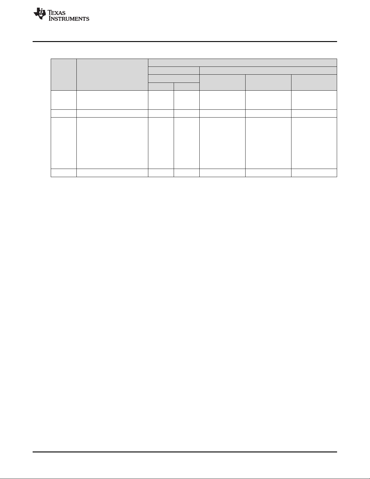
www.ti.com
Command Handler Supported Commands
Table G-1. DLP NIRscan Nano Supported Commands (continued)
COMMUNICATIONS INTERFACE
READ /
WRITE
READ Get time and date 0x03 0x0C Time Service 5020-4E49- 5020-4E49-
WRITE Set Tiva in hybernation mode 0x03 0x0D
READ 0x04 0x00 Information Service 5020-4E49- 5020-4E49-
READ Read Photodetector 0x04 0x02
DESCRIPTION
Read number of scan files
stored in microSD card
USB BLUETOOTH
OPCODE
BYTE 1 BYTE 2
SERVICE NAME SERVICE UUID
GATT Date and 0x53455203-444C- 0x4348410C-444C-
Table I-4 52204E616E6F 52204E616E6F
GATT Scan Data 0x53455206-444C- 0x4348411A-444C-
Table I-7 52204E616E6F 52204E616E6F,
CHARACTERISTI
C UUID
0x43484119-444C-
5020-4E49-
52204E616E6F,
0x4348411B-444C-
5020-4E49-
52204E616E6F
DLPU030B–June 2015–Revised July 2015 DLP NIRscan Nano Command Description
Submit Documentation Feedback
Copyright © 2015, Texas Instruments Incorporated
61
Page 62

Report ID = 0 Command Byte Sequence Byte Length LSB Length MSB OpCode 1 OpCode 2 Data Bytes Data Bytes
Byte 0 Byte 1 Byte 2 Byte 3 Byte 4 Byte 5 Byte 6 Byte 7 Byte N
…
R/W Reply Error Reserved
7 6 5 4:0
USB Communications
The DLP NIRscan Nano communicates using USB 1.1 human interface device (HID) to exchange
commands and data with a host processor or PC. The USB commands are variable length data packets
that are sent with the least significant byte first. The maximum HID packet length is 64 bytes.
The DLP NIRscan Nano enumerates as a Texas Instruments HID device with vendor ID = 0x0451 and
product ID = 0x4200.
USB Transaction Sequence
The USB 1.1 HID protocol has the structure shown in Figure H-1:
Appendix H
DLPU030B–June 2015–Revised July 2015
DLP NIRscan Nano USB Communications
Figure H-1. USB HID Protocol
H.0.0.1 USB Read Transaction Sequence
To issue a read command, the host must perform the following steps:
1. Host sends the Report ID byte, which is set to 0.
2. Host sends the Command ID byte, where:
• Bit 6 is set to 0x1 to indicate the host wants a reply from the device.
• Bit 7 is set to 0x1 to indicate a read transaction.
3. Host sends the Sequence byte. When a single command is more than 64 bytes, it is sent as multiple
USB packets and the sequence byte is used to number the packets so the device can assemble them
in the right sequence. Otherwise, this value is irrelevant and generally set to 0.
4. Host sends two bytes with the length of the data packet. This length denotes the number of data bytes
in the packet and excludes the number of bytes in steps 1 through 4. It denotes the total number of
bytes sent in steps 5 (command bytes) and 6 (data bytes).
5. Host sends two OpCode bytes: OpCode Byte 1 and OpCode Byte 2.
6. Host sends data appropriate to command.
7. After completion of this command, DLP NIRscan Nano responds with a packet that includes:
(a) Byte with the command requested by the host (the matching Sequence byte)
(b) Length of the data packet
(c) Data requested
62
DLP NIRscan Nano USB Communications DLPU030B–June 2015–Revised July 2015
Copyright © 2015, Texas Instruments Incorporated
Submit Documentation Feedback
Page 63

www.ti.com
H.0.0.2 USB Write Transaction Sequence
To issue a write command, the host must perform the following steps:
1. Host sends the Report ID byte, which is set to 0.
2. Host sends the Flags byte, where
• Bit 6 is set to 0x1 to indicate the host wants a reply from the device. The device responds with the
NACK bit set if an unknown command was received or there was any error in processing the
command due to invalid parameters or other reasons..
• Bit 7 is set to 0x1 to indicate a read transaction
3. Host sends the Sequence byte. When a single command is more than 64 bytes, it is sent as multiple
USB packets and the sequence byte is used to number the packets so the device can assemble them
in the right sequence. In other cases, this value is irrelevant and generally set to 0.
4. Host sends two bytes with the length of the data packet. This length denotes the number of data bytes
in the packet and excludes the number of bytes in steps 1 through 4. It denotes the total number of
bytes sent in steps 5 (command bytes) and 6 (data bytes).
5. Host sends three OpCode bytes: OpCode Byte 1 and OpCode Byte 2.
6. Host sends data appropriate to command.
7. After completion of this command, DLP NIRscan Nano responds with a packet that includes a byte
with the command requested by the host. This occurs only if bit 6 was set in the Flags byte.
DLPU030B–June 2015–Revised July 2015 DLP NIRscan Nano USB Communications
Submit Documentation Feedback
Copyright © 2015, Texas Instruments Incorporated
63
Page 64

www.ti.com
64
DLP NIRscan Nano USB Communications DLPU030B–June 2015–Revised July 2015
Copyright © 2015, Texas Instruments Incorporated
Submit Documentation Feedback
Page 65

DLP NIRscan Nano Bluetooth Communications
I.1 Bluetooth Communications
The DLP NIRscan Nano wirelessly communicates using Bluetooth Low Energy version 4.0 This wireless
communication uses two main profiles for discovery and communication with a remote host:
• GAP: Generic access profile for basic discovery and establishing connections.
• GATT: Generic attribute profile for commands and data transfer.
The DLP NIRscan Nano supports Bluetooth version 4.0 specification. When the Bluetooth sub-system is
activated, the DLP NIRscan Nano broadcasts its availability while a smartphone, tablet or PC acts as an
observer. Once connected, the DLP NIRscan Nano acts as a server for the GATT profile while the
smartphone, tablet, or PC acts as a client.
I.1.1 GATT Supported Services
The DLP NIRscan Nano Bluetooth GATT Profile supports the following services:
• Battery Service (BAS) to provide battery charge capacity.
• Device Information Service (DIS) to provide manufacturer Name, model number, serial number,
hardware revision, spectrum library revision, and Tiva software revision.
• GATT General Information Service to provide temperature, humidity, status, hours of use, lamp hours,
and battery recharge cycles.
• GATT Date and Time Service to synchronize date and time information between smartphone, tablet, or
PC to the Tiva's realtime clock.
• GATT Calibration Information Service to provide calibration coefficients
• GATT Scan Configuration Information Service to provide stored configurations and scan configuration
data.
• GATT Scan Data Information Service to initiate scan, clear scan data, and return stored scan data.
A GATT service has a universally unique identifier (UUID) used to identify every service. A UUID is a 128bit value. However, common or frequently used services that are included in the BLE specifications and/or
certified by Bluetooth.org are shortened to 16-bit UUID to improve efficiency.
Each service is composed of a set of characteristics. Each characteristic contains a value with properties
for how the value is accessed and information on how the value is displayed or represented. The
properties are:
• R = Read.
• W = Write.
• WWoR = Write without response. Not used in DLP NIRscan Nano Bluetooth implementation.
• S = Signed write. Not used in DLP NIRscan Nano Bluetooth implementation.
• N = Notify.
• I = Indicate.
• WA = Writable auxiliaries. Not used in DLP NIRscan Nano Bluetooth implementation.
• B = Broadcast. Not used in DLP NIRscan Nano Bluetooth implementation.
• EP = Extended properties. Not used in DLP NIRscan Nano Bluetooth implementation.
Appendix I
DLPU030B–June 2015–Revised July 2015
DLPU030B–June 2015–Revised July 2015 DLP NIRscan Nano Bluetooth Communications
Submit Documentation Feedback
Copyright © 2015, Texas Instruments Incorporated
65
Page 66

Bluetooth Communications
An "X" in a supported property indicates the properties supported by a characteristic. Empty columns
indicate properties not supported by the characteristic.
A data size entry with an MP value represents multiple packets. All data is transmitted little-endian.
SERVICE UUID DESCRIPTION
0x180A DEVICE INFORMATION SERVICE (DIS)
CHARACTERIS DATA
TIC UUID FORMAT
0x2829 Manufacturer name string string 1 X
0x2A24 Model number string string 1 X aracteristic.mode
0x2A25 Serial number string string 1 X aracteristic.serial
0x2A27 Hardware revision string string 1 X
0x2A26 Tiva firmware revision string string 1 X
0x2A28 Spectrum library revision string 2 X
www.ti.com
Table I-1. Device Information Service (DIS)
DESCRIPTION SIZE NOTES
DATA
(BYTES)
unsigned aracteristic.softw
integer are_revision_stri
SUPPORTED
PROPERTIES
R W N I
org.bluetooth.ch
aracteristic.manu
facturer_name_s
tring
org.bluetooth.ch
l_number_string
org.bluetooth.ch
_number_string
org.bluetooth.ch
aracteristic.hard
ware_revision_st
ring
org.bluetooth.ch
aracteristic.firmw
are_revision_stri
ng
org.bluetooth.ch
ng
Table I-2. Battery Service (BAS)
SERVICE UUID DESCRIPTION
0x180F BATTERY SERVICE (BAS)
CHARACTERIS DATA
TIC UUID FORMAT
0x2A19 Battery level 1 X ice. Value
DESCRIPTION SIZE NOTES
unsigned
integer
DATA
(BYTES)
SUPPORTED
PROPERTIES
R W N I
org.bluetooth.ser
vice.battery_serv
reported in the
range of 0-100.
66
DLP NIRscan Nano Bluetooth Communications DLPU030B–June 2015–Revised July 2015
Copyright © 2015, Texas Instruments Incorporated
Submit Documentation Feedback
Page 67

www.ti.com
Table I-3. GATT General Information Service
SERVICE UUID DESCRIPTION
0x53455201-
444C-5020-
4E49-
52204E616E6F
CHARACTERIS DATA
TIC UUID FORMAT
0x43484101-
444C-5020-
4E49-
52204E616E6F
0x43484102-
444C-5020- unsigned
4E49- integer
52204E616E6F
0x43484103-
444C-5020- Device status unsigned
4E49- (Reserved for future support) integer
52204E616E6F
0x43484104-
444C-5020- Error status unsigned
4E49- (Reserved for future support) integer
52204E616E6F
0x43484105-
444C-5020-
4E49-
52204E616E6F
0x43484106-
444C-5020- unsigned
4E49- integer
52204E616E6F
0x43484107-
444C-5020- Number of hours of use unsigned
4E49- (Reserved for future support) integer
52204E616E6F
0x43484108-
444C-5020- Number of battery recharge cycles unsigned
4E49- (Reserved for future support) integer
52204E616E6F
0x43484109-
444C-5020- Total lamp hours unsigned
4E49- (Reserved for future support) integer
52204E616E6F
0x4348410A-
444C-5020- Error log
4E49- (Reserved for future support)
52204E616E6F
Temperature measurement integer 2 X X
Humidity measurement 2 X X
Temperature threshold integer 2 X
Humidity threshold 2 X
DESCRIPTION SIZE NOTES
GATT GENERAL INFORMATION SERVICE
DATA
(BYTES)
2 X X
2 X X
2 X
2 X
2 X
string 1 X
Bluetooth Communications
SUPPORTED
PROPERTIES
R W N I
Integer value
returned in
hundredths.
Divide by 100 to
get the actual
floating point
number.
Value set in
hundredths.
Input truncated
integer of actual
value multiplied
by 100.
DLPU030B–June 2015–Revised July 2015 DLP NIRscan Nano Bluetooth Communications
Submit Documentation Feedback
Copyright © 2015, Texas Instruments Incorporated
67
Page 68

Bluetooth Communications
SERVICE UUID DESCRIPTION
0x53455203-444C-
5020-4E49- GATT CURRENT DATE AND TIME
52204E616E6F
CHARACTERISTIC DATA DATA SIZE
UUID FORMAT (BYTES)
0x4348410C-444C-
5020-4E49- Current day of the week (0-6) 1 X
52204E616E6F
Table I-4. GATT Date and Time Service
DESCRIPTION
Current year (0-99: starting in year 2000) 1
Current month (1-12) 1
Current day (1-31) 1
Current hour (0-23) 1
Current minute (0-59) 1
Current second (0-59) 1
unsigned
integer
unsigned
integer
unsigned
integer
unsigned
integer
unsigned
integer
unsigned
integer
unsigned
integer
Table I-5. GATT Calibration Information Service
www.ti.com
SUPPORTED PROPERTIES
R W N I
SERVICE UUID DESCRIPTION
0x53455204-
444C-5020-
4E49-
52204E616E6F
CHARACTERIS DATA
TIC UUID FORMAT
0x4348410D-
444C-5020- Request Spectrum Calibration unsigned
4E49- Coefficients integer
52204E616E6F
0x4348412E- Each coefficient
444C-5020- Return Spectrum Calibration is a double data-
4E49- Coefficients type of 8 bytes.
52204E616E6F The data is sent
0x4348410F-
444C-5020- Request Reference Calibration unsigned
4E49- Coefficients integer
52204E616E6F
0x43484110- Serialized data;
444C-5020- Return Reference Calibration refer to spectrum
4E49- Coefficients C library for data
52204E616E6F structure.
0x43484111-
444C-5020- unsigned
4E49- integer
52204E616E6F
0x43484112- Serialized data;
444C-5020- refer to spectrum
4E49- C library for data
52204E616E6F structure.
Request Reference Calibration Matrix 1 X read. No data
Return Reference Calibration Matrix MP X
DESCRIPTION SIZE NOTES
GATT CALIBRATION INFORMATION SERVICE
DATA
(BYTES)
1 X read. No data
MP X
1 X read. No data
MP X
SUPPORTED
PROPERTIES
R W N I
Indicate intent to
transferred.
Send 6
coefficients.
in serialized
manner.
Indicate intent to
transferred.
Indicate intent to
transferred.
68
DLP NIRscan Nano Bluetooth Communications DLPU030B–June 2015–Revised July 2015
Copyright © 2015, Texas Instruments Incorporated
Submit Documentation Feedback
Page 69

www.ti.com
Bluetooth Communications
Table I-6. GATT Scan Configuration Information Service
SERVICE UUID DESCRIPTION
0x53455205-
444C-5020-
4E49-
52204E616E6F
CHARACTERIS DATA
TIC UUID FORMAT
0x43484113-
444C-5020- unsigned
4E49- integer
52204E616E6F
0x43484114-
444C-5020- unsigned No data
4E49- integer transmitted.
52204E616E6F
0x43484115-
444C-5020- List of 2 byte
4E49- indices.
52204E616E6F
0x43484116-
444C-5020- unsigned
4E49- integer
52204E616E6F
0x43484117- Serialized data;
444C-5020- refer to spectrum
4E49- C library for data
52204E616E6F structure.
0x43484118- Get/Set function.
444C-5020- Parameter
4E49- transmitted is a
52204E616E6F 2-byte index.
Number of stored configurations 2 X
Request stored configurations list 1 X
Return stored configurations list MP X
Request scan configuration data 2 X Index to read.
Return scan configuration data MP X
Active scan configuration 2 X X
DESCRIPTION SIZE NOTES
GATT SCAN CONFIGURATION INFORMATION SERVICE
DATA
(BYTES)
SUPPORTED
PROPERTIES
R W N I
Table I-7. GATT Scan Data Information Service
SERVICE UUID DESCRIPTION
0x53455206-
444C-5020-
4E49-
52204E616E6F
CHARACTERIS DATA
TIC UUID FORMAT
0x43484119-
444C-5020- unsigned
4E49- integer
52204E616E6F
0x4348411A-
444C-5020- unsigned No data
4E49- integer transmitted.
52204E616E6F
0x4348411B- Multiple packet
444C-5020- transfer of five 4-
4E49- byte indices per
52204E616E6F packet.
0x4348411C-
444C-5020- Limited to 15
4E49- bytes.
52204E616E6F
Number of stored scans 4 X
Stored scan indices list 4 X
Stored scan indices list MP X
Set scan name stub string 2 X
DESCRIPTION SIZE NOTES
GATT SCAN DATA INFORMATION SERVICE
DATA
(BYTES)
SUPPORTED
PROPERTIES
R W N I
DLPU030B–June 2015–Revised July 2015 DLP NIRscan Nano Bluetooth Communications
Submit Documentation Feedback
Copyright © 2015, Texas Instruments Incorporated
69
Page 70

Bluetooth Communications
SERVICE UUID DESCRIPTION
0x53455206-
444C-5020-
4E49-
52204E616E6F
CHARACTERIS DATA
TIC UUID FORMAT
0x4348411D-
444C-5020- unsigned
4E49- integer
52204E616E6F
0x4348411E-
444C-5020- unsigned
4E49- integer
52204E616E6F
0x4348411F-
444C-5020- unsigned Index of scan
4E49- integer data to read.
52204E616E6F
0x43484120-
444C-5020-
4E49-
52204E616E6F
0x43484121-
444C-5020- unsigned Index of scan
4E49- integer data to read.
52204E616E6F
0x43484122-
444C-5020- unsigned
4E49- integer
52204E616E6F
0x43484123-
444C-5020- unsigned
4E49- integer
52204E616E6F
0x43484124-
444C-5020- unsigned
4E49- integer
52204E616E6F
0x43484125-
444C-5020- unsigned Index of data to
4E49- integer read.
52204E616E6F
0x43484126-
444C-5020- unsigned
4E49- integer
52204E616E6F
www.ti.com
Table I-7. GATT Scan Data Information Service (continued)
GATT SCAN DATA INFORMATION SERVICE
DESCRIPTION SIZE NOTES
DATA
(BYTES)
Start scan 1 X X
Clear scan 4 X X
Request scan name 4 X
Return scan name string 20 X limited to 20
Request scan type 4 X
Return scan type 1 X
Request scan date/time 4 X
Return scan date/time 7 X format as GATT
Request packet format version 4 X
Return packet format version 4 X
SUPPORTED
PROPERTIES
R W N I
Parameter value:
0x00 = do not
store scan in
microSD card
0x01 = store
scan in microSD
card.
Notification
returned:
0xFF = scan
completed
Index of scan
data to clear.
Notification
returned:
0x00 = success
non-zero return
is an error
Scan name
characters.
Seven bytes
returned. Same
Date and Time
Service.
70
DLP NIRscan Nano Bluetooth Communications DLPU030B–June 2015–Revised July 2015
Copyright © 2015, Texas Instruments Incorporated
Submit Documentation Feedback
Page 71

www.ti.com
SERVICE UUID DESCRIPTION
0x53455206-
444C-5020-
4E49-
52204E616E6F
CHARACTERIS DATA
TIC UUID FORMAT
0x43484127-
444C-5020- unsigned Index of data to
4E49- integer read
52204E616E6F
0x43484128- Serialized data;
444C-5020- refer to spectrum
4E49- C library for data
52204E616E6F structure.
Request serialized scan data structure 4 X
Return serialized scan data structure MP X
I.2 Bluetooth Packets
Bluetooth transmits in short packet sizes. The typical maximum transmission unit for an iOS App is 20
bytes. Multiple packets are needed to transfer the following information to DLP NIRscan Nano:
• Spectrum Calibration Coefficients
• Reference Calibration Coefficients
• Stored Configurations List
• Scan Configuration Data
• Stored Scan Indices
• Serialized Scan Data Structure
The previous tables label the data size as MP to denote that multiple packets are used during transfer.
The packet structure is:
• First Packet:
– Packet Index: 00 (one byte)
– Data size in bytes (4 bytes)
• NthPacket:
– Packet Index: N-1 (one byte describing the current packet number, zero-based)
– Data Packet: data (up to 19 bytes)
Bluetooth Packets
Table I-7. GATT Scan Data Information Service (continued)
GATT SCAN DATA INFORMATION SERVICE
DESCRIPTION SIZE NOTES
DATA
(BYTES)
SUPPORTED
PROPERTIES
R W N I
DLPU030B–June 2015–Revised July 2015 DLP NIRscan Nano Bluetooth Communications
Submit Documentation Feedback
Copyright © 2015, Texas Instruments Incorporated
71
Page 72

Revision B History
www.ti.com
Revision B History
Changes from A Revision (June 2015) to B Revision .................................................................................................... Page
• Updated locations of firmware files in Section 3.1.4 ................................................................................ 29
• Deleted OpCode Byte 3................................................................................................................. 58
• Added USB Communications HID packet description .............................................................................. 62
NOTE: Page numbers for previous revisions may differ from page numbers in the current version.
Revision A History
Changes from Original (June 2015) to A Revision ......................................................................................................... Page
• Added missing thermistor from block diagram and moved red LED to bq24250 ................................................. 9
• Changed description to include more information................................................................................... 12
• Changed list of DLLs .................................................................................................................... 18
• Changed description of scan configuration parameters ............................................................................ 22
• Changed battery requirements......................................................................................................... 31
• Changed DLP Spectrum Library description......................................................................................... 37
• Added DLP Spectrum Library workflow diagrams................................................................................... 37
• Changed semaphore location to be outside of tasks ............................................................................... 40
• Added Bluetooth Client App Workflow................................................................................................ 40
• Changed software version numbers .................................................................................................. 48
• Added steps to compile NIRscanNanoGUI and its DLP Spectrum Library under Windows ................................... 53
• Changed Command Handler Table to show the exact USB commands and Bluetooth services............................. 58
• Added notes to the GATT services characteristics.................................................................................. 65
NOTE: Page numbers for previous revisions may differ from page numbers in the current version.
72
Revision History DLPU030B–June 2015–Revised July 2015
Copyright © 2015, Texas Instruments Incorporated
Submit Documentation Feedback
Page 73

IMPORTANT NOTICE
Texas Instruments Incorporated and its subsidiaries (TI) reserve the right to make corrections, enhancements, improvements and other
changes to its semiconductor products and services per JESD46, latest issue, and to discontinue any product or service per JESD48, latest
issue. Buyers should obtain the latest relevant information before placing orders and should verify that such information is current and
complete. All semiconductor products (also referred to herein as “components”) are sold subject to TI’s terms and conditions of sale
supplied at the time of order acknowledgment.
TI warrants performance of its components to the specifications applicable at the time of sale, in accordance with the warranty in TI’s terms
and conditions of sale of semiconductor products. Testing and other quality control techniques are used to the extent TI deems necessary
to support this warranty. Except where mandated by applicable law, testing of all parameters of each component is not necessarily
performed.
TI assumes no liability for applications assistance or the design of Buyers’ products. Buyers are responsible for their products and
applications using TI components. To minimize the risks associated with Buyers’ products and applications, Buyers should provide
adequate design and operating safeguards.
TI does not warrant or represent that any license, either express or implied, is granted under any patent right, copyright, mask work right, or
other intellectual property right relating to any combination, machine, or process in which TI components or services are used. Information
published by TI regarding third-party products or services does not constitute a license to use such products or services or a warranty or
endorsement thereof. Use of such information may require a license from a third party under the patents or other intellectual property of the
third party, or a license from TI under the patents or other intellectual property of TI.
Reproduction of significant portions of TI information in TI data books or data sheets is permissible only if reproduction is without alteration
and is accompanied by all associated warranties, conditions, limitations, and notices. TI is not responsible or liable for such altered
documentation. Information of third parties may be subject to additional restrictions.
Resale of TI components or services with statements different from or beyond the parameters stated by TI for that component or service
voids all express and any implied warranties for the associated TI component or service and is an unfair and deceptive business practice.
TI is not responsible or liable for any such statements.
Buyer acknowledges and agrees that it is solely responsible for compliance with all legal, regulatory and safety-related requirements
concerning its products, and any use of TI components in its applications, notwithstanding any applications-related information or support
that may be provided by TI. Buyer represents and agrees that it has all the necessary expertise to create and implement safeguards which
anticipate dangerous consequences of failures, monitor failures and their consequences, lessen the likelihood of failures that might cause
harm and take appropriate remedial actions. Buyer will fully indemnify TI and its representatives against any damages arising out of the use
of any TI components in safety-critical applications.
In some cases, TI components may be promoted specifically to facilitate safety-related applications. With such components, TI’s goal is to
help enable customers to design and create their own end-product solutions that meet applicable functional safety standards and
requirements. Nonetheless, such components are subject to these terms.
No TI components are authorized for use in FDA Class III (or similar life-critical medical equipment) unless authorized officers of the parties
have executed a special agreement specifically governing such use.
Only those TI components which TI has specifically designated as military grade or “enhanced plastic” are designed and intended for use in
military/aerospace applications or environments. Buyer acknowledges and agrees that any military or aerospace use of TI components
which have not been so designated is solely at the Buyer's risk, and that Buyer is solely responsible for compliance with all legal and
regulatory requirements in connection with such use.
TI has specifically designated certain components as meeting ISO/TS16949 requirements, mainly for automotive use. In any case of use of
non-designated products, TI will not be responsible for any failure to meet ISO/TS16949.
Products Applications
Audio www.ti.com/audio Automotive and Transportation www.ti.com/automotive
Amplifiers amplifier.ti.com Communications and Telecom www.ti.com/communications
Data Converters dataconverter.ti.com Computers and Peripherals www.ti.com/computers
DLP® Products www.dlp.com Consumer Electronics www.ti.com/consumer-apps
DSP dsp.ti.com Energy and Lighting www.ti.com/energy
Clocks and Timers www.ti.com/clocks Industrial www.ti.com/industrial
Interface interface.ti.com Medical www.ti.com/medical
Logic logic.ti.com Security www.ti.com/security
Power Mgmt power.ti.com Space, Avionics and Defense www.ti.com/space-avionics-defense
Microcontrollers microcontroller.ti.com Video and Imaging www.ti.com/video
RFID www.ti-rfid.com
OMAP Applications Processors www.ti.com/omap TI E2E Community e2e.ti.com
Wireless Connectivity www.ti.com/wirelessconnectivity
Mailing Address: Texas Instruments, Post Office Box 655303, Dallas, Texas 75265
Copyright © 2015, Texas Instruments Incorporated
 Loading...