

Page 1

DLP®LightCrafter™ Display 3310 EVM User's
Guide
User's Guide
Literature Number: DLPU063
January 2018
Page 2

Contents
1 DLP
®
LightCrafter™ Display 3310 EVM Overview..................................................................... 4
2 Safety Instructions ............................................................................................................... 5
3 Applicable Documents.......................................................................................................... 6
4 DLP LightCrafter Display 3310 EVM Components .................................................................... 7
5 Light Engine........................................................................................................................ 8
6 Quick-Start Procedure......................................................................................................... 10
7 Circuit Description.............................................................................................................. 12
7.1 Connectors and Switches on System Board ........................................................................... 12
7.2 Connectors on DLP LightCrafter Display Board........................................................................ 12
8 EVM Setup......................................................................................................................... 13
2
Contents
Copyright © 2018, Texas Instruments Incorporated
DLPU063–January 2018
Submit Documentation Feedback
Page 3

www.ti.com
1-1. DLP LightCrafter Display Complete EVM ................................................................................ 4
4-1. DLP LightCrafter Display EVM Block Diagram .......................................................................... 7
5-1. Optical Engine Dimensions................................................................................................. 8
5-2. Optical Engine View ......................................................................................................... 9
6-1. Optical Engine with Focus Adjustment.................................................................................. 10
8-1. DLP LightCrafter Display System Board ................................................................................ 13
8-2. Connection System Board and DLP LightCrafter Display Board .................................................... 14
8-3. DLP LightCrafter Display EVM ........................................................................................... 14
5-1. Optical Engine Specifications .............................................................................................. 8
6-1. LEDs on the DLP LightCrafter Display 3310 EVM..................................................................... 11
7-1. Connectors and Switches on System Board ........................................................................... 12
7-2. Connectors on the DLP LightCrafter Display Board ................................................................... 12
List of Figures
List of Tables
DLPU063–January 2018
Submit Documentation Feedback
Copyright © 2018, Texas Instruments Incorporated
List of Figures
3
Page 4
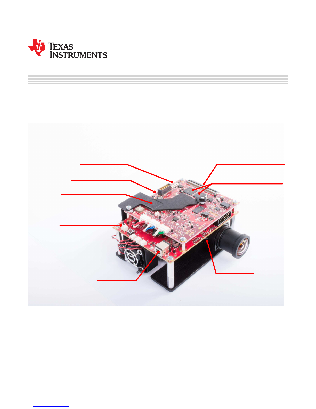
Power Connector
Projector
ON/OFF Switch
DLPA3000 PMIC
and LED Driver
DLPC3437
Display Controllers
Optical Module
With RGB LEDs
Mini-USB Connector
HDMI Connector
DLP3310 Digital
Micromirror Device
Chapter 1
DLPU063–January 2018
DLP®LightCrafter™ Display 3310 EVM Overview
This user’s guide presents an overview of the DLP®LightCrafter™ Display 3310 evaluation module (EVM)
and a general description of the main features and functions. It explains the first steps to getting started
and shows a detailed description of on board LEDs, connectors, and overall EVM assembly. It will give the
user a start with their first DLP LightCrafter Display 3310 evaluation module.
Figure 1-1. DLP LightCrafter Display Complete EVM
In addition to this document, reference the documents listed in Chapter 3.
LightCrafter, E2E are trademarks of Texas Instruments.
DLP is a registered trademark of Texas Instruments.
All other trademarks are the property of their respective owners.
4
DLP®LightCrafter™ Display 3310 EVM Overview
Copyright © 2018, Texas Instruments Incorporated
DLPU063–January 2018
Submit Documentation Feedback
Page 5
DLPU063–January 2018
Safety Instructions
CAUTION
Hot surface. To minimize risk of burns, do not touch.
WARNING
Possible hazardous optical radiation emitted from this product. Do
not stare at the operating lamp. May be harmful to the eye.
Chapter 2
WARNING
Observe handling precautions. Electrostatic sensitive devices.
WARNING
Always ensure all fans are running during operation to help avoid
overheating and ensure reliable operation.
DLPU063–January 2018
Submit Documentation Feedback
Copyright © 2018, Texas Instruments Incorporated
Safety Instructions
5
Page 6

Chapter 3
DLPU063–January 2018
Applicable Documents
The following documents are applicable to the DLP LightCrafter Display 3310 EVM and are available at
TI.com (www.ti.com).
• DLP3310 0.33 1080p DMD (DLPS077)
• DLPA3000 PMIC and High-Current LED Driver IC (DLPS052)
• DLPC3437 Display Controller (DLPS084)
• DLPC3437 Software Programmer's Guide (DLPU062)
• DLP®LightCrafter™ Display EVM GUI Tool (DLPU021)
If you need assistance, refer to the DLP Products and MEMS TI E2E™ community support forums.
6
Applicable Documents
Copyright © 2018, Texas Instruments Incorporated
DLPU063–January 2018
Submit Documentation Feedback
Page 7
Optical
Engine
DLPC3437
(Slave)
DLPA3000
Flex Connector
Parallel I/F
24 Bit Data
CTRL
I2C
1.8V
VBIAS, VRST, VOFS
VIN
1.8V
1.1V
IT6801
Parallel I/F
24 Bit Data
CTRL
HDMI
EE
PROM
USB
MSP430
19V DC
VIN
PROJ
_
ON
USB-Serial
Bridge
Controller
CY7C65215
SPI_0
I2C
DMD Flex Cable
60 pin Board Connector
SPI_0
1.8V
1.1V
SW_ONOFF
I2C
Flash
64Mb
SPI
1.8V
LED Cable
(RED)
LED Cable
(GREEN)
LED Cable
(BLUE)
FPGA
Parallel I/F
Data/Ctrl
Flash
32Mb
SPI
DDR3
32Mb
Addr/
Data
sI2C
DLPC3437
(Master)
Flash
64Mb
SPI
mI2C
Parallel I/F
Data/Ctrl
Syncs
PROJ_ON
Sub-LVDS DATA - B
Ctrl
PROJ_
ON
RED GREEN BLUE
REDGREENBLUE
Sub-LVDS DATA - A
CTRL
1.1V
RESETZ
SPI_1
LED_SEL(2)
VLED (R/G/B)
ACT
DRVR
Ctrl/
Data
ACT_
P/N
ACT_P/N
ACT_
P/N
Conn
Conn
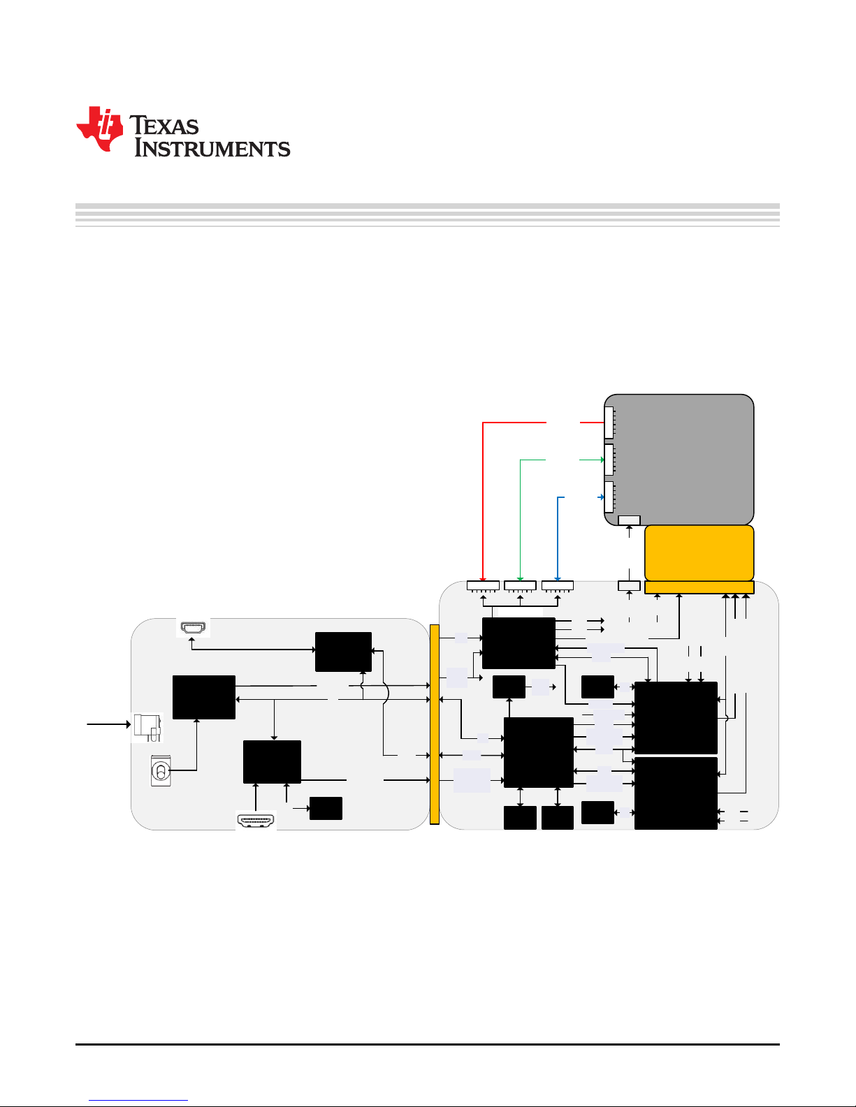
Chapter 4
DLPU063–January 2018
DLP LightCrafter Display 3310 EVM Components
The DLP LightCrafter Display module consists of three subsystems:
• Light engine – Includes the optics, red, green, and blue LEDs, and a Full-HD DMD capable of 300
lumens out-of-the-box.
• Display board – Includes the DLP chipset comprised of DLPC3437 controllers and DLPA3000
PMIC/LED driver.
• System board – Includes the MSP430, ITE HDMI receiver, USB-Serial Bridge controller and several
connectors for external inputs (HDMI, USB, and so forth).
Figure 4-1. DLP LightCrafter Display EVM Block Diagram
DLPU063–January 2018
Submit Documentation Feedback
Copyright © 2018, Texas Instruments Incorporated
DLP LightCrafter Display 3310 EVM Components
7
Page 8

101.92mm
30.00mm
87.70mm
Light Engine
The optical engine in the EVM is developed by Young Optics and is production ready.
The light engine consists of the following components:
• DLP3310 (0.33-inch Full-HD DMD)
• Osram red, green, and blue LEDs
Table 5-1. Optical Engine Specifications
PARAMETER MIN TYP MAX UNIT
Brightness at 6-A RGB LED Current 320 Lm
RGB LED Current 6 A
Brightness Uniformity 85%
Throw Ratio 1.2
Offset 100%
Focusable Diagonal Image Size 60 120 inch
Chapter 5
DLPU063–January 2018
8
Light Engine
Figure 5-1. Optical Engine Dimensions
Copyright © 2018, Texas Instruments Incorporated
DLPU063–January 2018
Submit Documentation Feedback
Page 9

www.ti.com
Figure 5-2. Optical Engine View
DLPU063–January 2018
Submit Documentation Feedback
Copyright © 2018, Texas Instruments Incorporated
Light Engine
9
Page 10

Focus
Adjustment
Chapter 6
DLPU063–January 2018
Quick-Start Procedure
This quick-start assumes default conditions as shipped.
1. Power up the DLP LightCrafter™ Display 3310 EVM by applying an external DC power supply (19-V
DC, 3.42 A) to the J4 connector. External Power Supply Requirements:
• Nominal Output Voltage: 19 VDC
• Minimum Output Current: 2.5 A; Max Output Current: 3.42 A
• Efficiency Level: VI
NOTE: TI recommends using an external power supply that complies with applicable regional safety
standards such as UL, CSA, VDE, CCC, and PSE.
NOTE: The P5V_VIN (D1) and P3P3V_SB (D7) LEDs on the System board will turn on to indicate that
5-V power and 3.3-V power are applied.
2. Move SW2 switch to the ON position to turn on the DLP LightCrafter Display 3310 EVM. When the
DLP LightCrafter Display 3310 EVM is turned on, the PROJ_ON LED (D5) will turn on.
3. After the DLP LightCrafter Display 3310 EVM is turned on; the projector will default to displaying a DLP
LightCrafter Display splash image.
4. The focus of the image can be adjusted manually on the optical engine.
Figure 6-1. Optical Engine with Focus Adjustment
5. Connect the USB to the DLP LightCrafter™ Display 3310 EVM and open the latest GUI on your
computer. If needed, connect an HDMI source to the EVM and communicate to the EVM via the GUI
software.
6. When turning off the projector, turn off the SW2 switch prior to removing the power cable.
Note: To avoid potential damage to the DMD, it is recommended to turn off the projector with the SW2
switch before disconnecting the power.
There are fourteen indicator LEDs on the DLP LightCrafter Display 3310 EVM (Display and System
boards), and they are defined in Table 6-1:
10
Quick-Start Procedure
Copyright © 2018, Texas Instruments Incorporated
DLPU063–January 2018
Submit Documentation Feedback
Page 11

www.ti.com
Table 6-1. LEDs on the DLP LightCrafter Display 3310 EVM
Board LED Reference
System D1 P5V_VIN Regulated 5-V power on.
System D3 MSP430_REQ
System D4 MSP430_ACK
System D5 PROJ_ON On when Projector is turned on via SW_ONOFF
System D6 RESETZ OFF when Projector is turned on via SW_ONOFF.
System D7 P3P3V_SB Regulated 3.3-V power on.
System D8
System D9 GPIO_1 Blinking when PC is communicating to flash over SPI.
System D10 GPIO_0 Blinking when PC is communicating to DLPC3437 over I2C.
Display D1 P12V Regulated 12-V power on.
Display D2 DONE ON when FPGA configuration is completed.
Display D7 INIT_B
Display D8 mHOST_IRQ
Display D9 sHOST_IRQ
Signal
Indication
ON when Cypress CY65215 requests the MSP430 to give Cypress master
control of the I2C bus.
ON when Cypress CY65215 is I2C master. OFF when MSP430 is I2C
master.
MSP_LED2_ONZON when HDMI cable is plugged in and external video is detected. OFF
when external video is not detected.
On when FPGA initialization is completed. OFF indicates that the FPGA is
in reset or when there is a configuration error.
ON during Master DLPC3437 Boot. OFF when projector is running.
Indication of Master DLPC3437 boot-up completed and ready to receive
commands.
ON during Slave DLPC3437 Boot. OFF when projector is running.
Indication of Slave DLPC3437 boot-up completed and ready to receive
commands.
Description
DLPU063–January 2018
Submit Documentation Feedback
Copyright © 2018, Texas Instruments Incorporated
Quick-Start Procedure
11
Page 12

7.1 Connectors and Switches on System Board
Table 7-1. Connectors and Switches on System Board
CONNECTORS/ HEADERS/ SWITCHES DESCRIPTION
J1 MSP430 JTAG Programming interface connector.
J2 Reserved (not installed by default).
J3 Reserved (not installed by default).
J4 Connector for 19-V external power supply interface.
J5 Reserved (not installed by default).
J6 Header for EDID programming.
J7 Header for 5-V DC power (used for LED cooling fan).
J8 Header for 5-V DC power (used for LED cooling fan).
J9 Header for 5-V DC power (used for LED cooling fan).
J10 Connector (60-pin) for DLP LightCrafter Display board interface.
J11 Connector for HDMI input.
J12 Connector for USB cable.
J13 Connector for the I2C interface (DevaSys box, not installed by default).
SW1 Reserved.
SW2 Projector ON/OFF Switch.
Chapter 7
DLPU063–January 2018
Circuit Description
7.2 Connectors on DLP LightCrafter Display Board
Table 7-2. Connectors on the DLP LightCrafter Display Board
CONNECTORS DESCRIPTION
J1 Reserved (not installed by default).
J2 Reserved (not installed by default).
J3 Reserved (not installed by default).
J4 Reserved (not installed by default).
J5 Connector for optical engine flex cable.
J6 Reserved (not installed by default).
J7 Reserved (not installed by default).
J8 Connector for Green LED cable.
J9 Connector for Blue LED cable.
J10 Connector for the DMD interface flex cable.
J11 Connector for Red LED cable.
J12 Connector (60-pin) for FPD interface.
J13 Connector (60-pin) for DLP LightCrafter System board interface.
12
Circuit Description
Copyright © 2018, Texas Instruments Incorporated
DLPU063–January 2018
Submit Documentation Feedback
Page 13
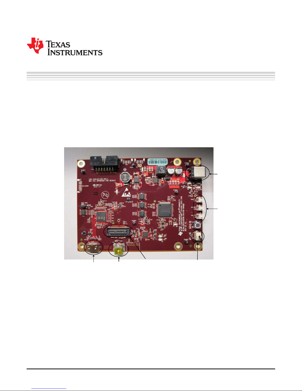
Mini-HDMI
Connector
Mini-USB
Connector
DLP LightCrafter
TM
Display Board
Connector
Projector
ON/OFF Switch
19V Power
Input
Connector
5V Fan Power
Connectors
Chapter 8
DLPU063–January 2018
EVM Setup
The DLP LightCrafter Display 3310 EVM is composed of three parts:
• System board
• DLP LightCrafter Display board
• Engine with LED connections and Flex cables
The system board contains the connector for the power supply, a USB connector to communicate to the
DLP LightCrafter Display software, HDMI, and the connector for the DLP LightCrafter Display board. The
system board also contains a switch to turn on the projector in case the DLP LightCrafter Display board
and the engine are connected. Figure 8-1 shows the main connectors on the system board.
Figure 8-1. DLP LightCrafter Display System Board
DLPU063–January 2018
Submit Documentation Feedback
Copyright © 2018, Texas Instruments Incorporated
EVM Setup
13
Page 14

DMD
Flex Cable
Connector
Red/Green/Blue
LED Connectors
Actuator
Flex Cable
Connector
www.ti.com
The DLP LightCrafter Display board contains the RGB LED connectors, the Flex cable connector, and the
system board connector. To connect the system board to the DLP LightCrafter Display board, refer to
Figure 8-2. Note that the system board connector on the DLP LightCrafter Display board is on the bottom,
while the LED and Flex cable connectors are on the top.
Figure 8-2. Connection System Board and DLP LightCrafter Display Board
Figure 8-3 shows the display board and how it connects to the system board. The different connectors for
each LED are named on the board as well as on the light engine.
Always ensure a good connection of the flex cables and LED cables to the DLP LightCrafter Display board
before turning it on.
Figure 8-3. DLP LightCrafter Display EVM
14
EVM Setup
Copyright © 2018, Texas Instruments Incorporated
DLPU063–January 2018
Submit Documentation Feedback
Page 15

IMPORTANT NOTICE FOR TI DESIGN INFORMATION AND RESOURCES
Texas Instruments Incorporated (‘TI”) technical, application or other design advice, services or information, including, but not limited to,
reference designs and materials relating to evaluation modules, (collectively, “TI Resources”) are intended to assist designers who are
developing applications that incorporate TI products; by downloading, accessing or using any particular TI Resource in any way, you
(individually or, if you are acting on behalf of a company, your company) agree to use it solely for this purpose and subject to the terms of
this Notice.
TI’s provision of TI Resources does not expand or otherwise alter TI’s applicable published warranties or warranty disclaimers for TI
products, and no additional obligations or liabilities arise from TI providing such TI Resources. TI reserves the right to make corrections,
enhancements, improvements and other changes to its TI Resources.
You understand and agree that you remain responsible for using your independent analysis, evaluation and judgment in designing your
applications and that you have full and exclusive responsibility to assure the safety of your applications and compliance of your applications
(and of all TI products used in or for your applications) with all applicable regulations, laws and other applicable requirements. You
represent that, with respect to your applications, you have all the necessary expertise to create and implement safeguards that (1)
anticipate dangerous consequences of failures, (2) monitor failures and their consequences, and (3) lessen the likelihood of failures that
might cause harm and take appropriate actions. You agree that prior to using or distributing any applications that include TI products, you
will thoroughly test such applications and the functionality of such TI products as used in such applications. TI has not conducted any
testing other than that specifically described in the published documentation for a particular TI Resource.
You are authorized to use, copy and modify any individual TI Resource only in connection with the development of applications that include
the TI product(s) identified in such TI Resource. NO OTHER LICENSE, EXPRESS OR IMPLIED, BY ESTOPPEL OR OTHERWISE TO
ANY OTHER TI INTELLECTUAL PROPERTY RIGHT, AND NO LICENSE TO ANY TECHNOLOGY OR INTELLECTUAL PROPERTY
RIGHT OF TI OR ANY THIRD PARTY IS GRANTED HEREIN, including but not limited to any patent right, copyright, mask work right, or
other intellectual property right relating to any combination, machine, or process in which TI products or services are used. Information
regarding or referencing third-party products or services does not constitute a license to use such products or services, or a warranty or
endorsement thereof. Use of TI Resources may require a license from a third party under the patents or other intellectual property of the
third party, or a license from TI under the patents or other intellectual property of TI.
TI RESOURCES ARE PROVIDED “AS IS” AND WITH ALL FAULTS. TI DISCLAIMS ALL OTHER WARRANTIES OR
REPRESENTATIONS, EXPRESS OR IMPLIED, REGARDING TI RESOURCES OR USE THEREOF, INCLUDING BUT NOT LIMITED TO
ACCURACY OR COMPLETENESS, TITLE, ANY EPIDEMIC FAILURE WARRANTY AND ANY IMPLIED WARRANTIES OF
MERCHANTABILITY, FITNESS FOR A PARTICULAR PURPOSE, AND NON-INFRINGEMENT OF ANY THIRD PARTY INTELLECTUAL
PROPERTY RIGHTS.
TI SHALL NOT BE LIABLE FOR AND SHALL NOT DEFEND OR INDEMNIFY YOU AGAINST ANY CLAIM, INCLUDING BUT NOT
LIMITED TO ANY INFRINGEMENT CLAIM THAT RELATES TO OR IS BASED ON ANY COMBINATION OF PRODUCTS EVEN IF
DESCRIBED IN TI RESOURCES OR OTHERWISE. IN NO EVENT SHALL TI BE LIABLE FOR ANY ACTUAL, DIRECT, SPECIAL,
COLLATERAL, INDIRECT, PUNITIVE, INCIDENTAL, CONSEQUENTIAL OR EXEMPLARY DAMAGES IN CONNECTION WITH OR
ARISING OUT OF TI RESOURCES OR USE THEREOF, AND REGARDLESS OF WHETHER TI HAS BEEN ADVISED OF THE
POSSIBILITY OF SUCH DAMAGES.
You agree to fully indemnify TI and its representatives against any damages, costs, losses, and/or liabilities arising out of your noncompliance with the terms and provisions of this Notice.
This Notice applies to TI Resources. Additional terms apply to the use and purchase of certain types of materials, TI products and services.
These include; without limitation, TI’s standard terms for semiconductor products http://www.ti.com/sc/docs/stdterms.htm), evaluation
modules, and samples (http://www.ti.com/sc/docs/sampterms.htm).
Mailing Address: Texas Instruments, Post Office Box 655303, Dallas, Texas 75265
Copyright © 2018, Texas Instruments Incorporated
Page 16

Mouser Electronics
Authorized Distributor
Click to View Pricing, Inventory, Delivery & Lifecycle Information:
Texas Instruments:
DLPDLCR3310EVM
 Loading...