

Page 1

DLP®LightCrafter™ Evaluation Module (EVM)
User's Guide
Literature Number: DLPU006C
January 2012–Revised December 2013
Page 2

Contents
Preface ....................................................................................................................................... 7
1 DLP
2 Operating the DLP LightCrafter ........................................................................................... 18
®
LightCrafter™ Module Overview ................................................................................... 8
1.1 Welcome ..................................................................................................................... 8
1.2 What is in the LightCrafter EVM? ......................................................................................... 8
1.2.1 Light Engine ........................................................................................................ 9
1.2.2 Driver Board ....................................................................................................... 10
1.2.3 System Board ..................................................................................................... 12
1.3 DLP LightCrafter Embedded Software Overview ..................................................................... 13
1.3.1 DM365 Software .................................................................................................. 13
1.3.1.1 Serial Communication ..................................................................................... 13
1.3.2 FPGA Overview ................................................................................................... 13
1.3.3 MSP430 Overview and Shutdown Protection Modes ........................................................ 14
1.4 Other Items Needed for Operation ...................................................................................... 15
1.5 DLP LightCrafter Connections ........................................................................................... 15
1.6 DLP LightCrafter's Dimensions .......................................................................................... 16
2.1 Installing the GUI .......................................................................................................... 18
2.2 Connecting to a PC ....................................................................................................... 18
2.2.1 Installing the RNDIS Driver on Windows XP .................................................................. 20
2.2.2 Installing the RNDIS Driver on Windows 7 .................................................................... 20
2.2.3 Enabling the RNDIS Driver on Linux ........................................................................... 23
2.2.4 Fixing the USB Start-Up Delay in Windows ................................................................... 25
2.2.5 Changing the DLP LightCrafter's IP Address ................................................................. 27
2.2.6 Connecting Multiple DLP LightCrafter's to One PC .......................................................... 28
2.3 Selecting the Display Mode .............................................................................................. 29
2.4 Setting the LED Current .................................................................................................. 30
2.5 Controlling Image Orientation ............................................................................................ 31
2.6 Triggering External Peripherals (Camera and So Forth) ............................................................. 32
2.7 Streaming 24-bit RGB Video from the HDMI Port ..................................................................... 34
2.8 Creating Pattern Sequences ............................................................................................. 35
2.8.1 Internal Stored Pattern Sequences ............................................................................ 35
2.8.1.1 Hardwired Pattern Sequences ............................................................................ 39
2.8.1.2 Multiple Bit-Depth and Multiple Color Pattern Sequences ............................................ 40
2.8.2 External Pattern Sequences Streaming from HDMI Port ................................................... 44
2.8.3 Extended Pattern Sequences ................................................................................... 44
2.9 Uploading Static Images or Colors ...................................................................................... 45
2.10 Using Test Patterns ....................................................................................................... 46
2.11 Saving and Loading Solutions ........................................................................................... 46
2.12 Capturing Images using the Camera Connector ...................................................................... 47
2.13 Upgrading Firmware ...................................................................................................... 48
2.13.1 Updating the MSP430, FPGA, DLPC300, or EDID using the GUI ........................................ 48
2.13.2 Updating the DM365 Firmware ................................................................................ 50
2.13.2.1 Setting up the SD Card on Windows .................................................................... 50
2.13.2.2 Setting up the SD Card on Linux ......................................................................... 53
2.13.2.3 Installing the DM365 Firmware into the NAND ......................................................... 53
2
Contents DLPU006C–January 2012–Revised December 2013
Copyright © 2012–2013, Texas Instruments Incorporated
Submit Documentation Feedback
Page 3

www.ti.com
2.13.2.4 Booting from the SD Card ................................................................................. 54
2.14 Changing the Splash Screens ........................................................................................... 54
2.15 Loading Images from the SD Card with Slide Show Mode .......................................................... 54
3 Developing with the DLP LightCrafter .................................................................................. 55
3.1 Compiling the GUI Using QT Creator ................................................................................... 55
3.2 Compiling the MSP430 Firmware Using Code Composer ........................................................... 55
3.3 Developing with the TI DVSDK .......................................................................................... 55
4 Pattern Sequences ............................................................................................................ 56
4.1 Pattern Sequence Background .......................................................................................... 56
4.2 External Patterns .......................................................................................................... 57
4.3 Internal Patterns ........................................................................................................... 58
5 Connectors ....................................................................................................................... 59
5.1 Trigger Connector ......................................................................................................... 59
5.2 Camera Connector ........................................................................................................ 59
5.3 UART ........................................................................................................................ 60
5.4 I
2
C ........................................................................................................................... 60
5.5 Fan .......................................................................................................................... 60
5.6 Power ....................................................................................................................... 61
Revision A History ...................................................................................................................... 62
Revision B History ...................................................................................................................... 62
Revision C History ...................................................................................................................... 62
DLPU006C–January 2012–Revised December 2013 Contents
Submit Documentation Feedback
Copyright © 2012–2013, Texas Instruments Incorporated
3
Page 4

www.ti.com
List of Figures
1. DLP LightCrafter Evaluation Module .................................................................................... 7
1-1. DLP LightCrafter Block Diagram.......................................................................................... 9
1-2. 0.3-inch DMD Pixel Geometry............................................................................................. 9
1-3. DLP LightCrafter Driver Board Block Diagram ........................................................................ 11
1-4. DLP LightCrafter System Board Block Diagram....................................................................... 12
1-5. DM365 DVSDK Software Platform...................................................................................... 13
1-6. DLP LightCrafter FPGA Block Diagram ................................................................................ 14
1-7. DLP LightCrafter Connector Locations ................................................................................. 16
1-8. DLP LightCrafter Module Dimensions .................................................................................. 17
2-1. DLP LightCrafter GUI Connect Button.................................................................................. 19
2-2. DLP LightCrafter GUI Disconnect Button .............................................................................. 19
2-3. Windows XP Found New Hardware Popup............................................................................ 20
2-4. Windows XP Found New Hardware Wizard ........................................................................... 20
2-5. Windows 7 Driver Software Installation Window ...................................................................... 21
2-6. Windows 7 Device Manager Window................................................................................... 21
2-7. Windows 7 Update Driver Software Search or Browse Window ................................................... 22
2-8. Windows 7 Update Driver Software Select Device Window ........................................................ 22
2-9. Windows 7 Update Driver Software Select Network Driver Window ............................................... 23
2-10. Windows 7 Update Driver Software Successfully Updated Window ............................................... 23
2-11. Ubuntu Command Terminal and "interfaces" File..................................................................... 24
2-12. Ubuntu Command Terminal "ifconfig" Result Before USB Setup ................................................... 24
2-13. Ubuntu Command Terminal "ifconfig" Result After USB Setup .................................................... 25
2-14. Windows 7 Network Connections Window ............................................................................ 25
2-15. Windows 7 Network Connections Identifying Local Area Connection ............................................. 26
2-16. Windows 7 Command Window Local Area Connection IPv4 Address ............................................. 26
2-17. Windows 7 Local Area Connection Properties ........................................................................ 26
2-18. Windows 7 Local Area Connection TCP/IPv4 Properties............................................................ 27
2-19. DLP LightCrafter GUI Connection Tab ................................................................................. 27
2-20. DLP LightCrafter GUI Connection New IP Address Textbox ........................................................ 28
2-21. DLP LightCrafter GUI Changing IP Popup............................................................................. 28
2-22. DLP LightCrafter GUI Connection Current IP Address Textbox .................................................... 28
2-23. DLP LightCrafter GUI Display Mode Setting........................................................................... 29
2-24. DLP LightCrafter GUI Display Mode Options.......................................................................... 29
2-25. DLP LightCrafter GUI Display Mode Set Button....................................................................... 30
2-26. DLP LightCrafter GUI LED Current Settings........................................................................... 30
2-27. DLP LightCrafter GUI LED Current Setting Active Cooling Needed................................................ 31
2-28. DLP LightCrafter GUI LED Current Setting Not Recommended .................................................... 31
2-29. DLP LightCrafter GUI LED Current Setting Set Button............................................................... 31
2-30. DLP LightCrafter GUI Image Orientation Settings .................................................................... 32
2-31. DLP LightCrafter GUI Output Trigger Settings ........................................................................ 33
2-32. DLP LightCrafter GUI Output Trigger Enable Checkbox............................................................. 33
2-33. DLP LightCrafter GUI Output Trigger Set Button ..................................................................... 33
2-34. DLP LightCrafter GUI RGB Video Streaming Selected on HDMI Port Tab........................................ 34
2-35. DLP LightCrafter GUI RGB Video Streaming Set Button ............................................................ 35
2-36. DLP LightCrafter GUI Sequence Settings Tab in Stored Pattern Sequence Tab................................. 36
2-37. Relationship between Trigger Period, Trigger Delay, and Exposure Time ........................................ 37
2-38. DLP LightCrafter GUI Pattern Sequence Settings Set Button....................................................... 37
4
List of Figures DLPU006C–January 2012–Revised December 2013
Copyright © 2012–2013, Texas Instruments Incorporated
Submit Documentation Feedback
Page 5

www.ti.com
2-39. DLP LightCrafter GUI Load Pattern Images ........................................................................... 38
2-40. DLP LightCrafter GUI Select Images Window......................................................................... 38
2-41. DLP LightCrafter GUI Upload All Pattern Images Button ............................................................ 39
2-42. DLP LightCrafter GUI Pattern Sequence Control Start Button ...................................................... 39
2-43. DLP LightCrafter GUI Hardwired Pattern Sequence Settings and Pattern Selection ............................ 40
2-44. MBMC Pattern Sequence Output Example............................................................................ 41
2-45. DLP LightCrafter GUI Multiple Bit and Multiple Color Sequence Settings Tab in Stored Pattern Sequence
2-46. DLP LightCrafter GUI Multiple Bit and Multiple Color Sequence Settings Tab in Stored Pattern Sequence
2-47. DLP LightCrafter GUI Example Sequence Settings for MBMC Sequence ........................................ 43
2-48. DLP LightCrafter GUI External Streaming Pattern Sequence Settings in HDMI Port Tab....................... 44
2-49. DLP LightCrafter GUI Static Image and Test Pattern Tab ........................................................... 45
2-50. DLP LightCrafter GUI Static Image Upload Button ................................................................... 45
2-51. DLP LightCrafter GUI Static Color Set Button......................................................................... 46
2-52. DLP LightCrafter GUI Internal Test Pattern Settings ................................................................. 46
2-53. DLP LightCrafter GUI Solution Tab..................................................................................... 47
2-54. DLP LightCrafter GUI Camera Tab ..................................................................................... 48
2-55. DLP LightCrafter GUI Firmware Upgrade Tab......................................................................... 49
2-56. DLP LightCrafter GUI Firmware Select Drop-Down Options ........................................................ 49
2-57. DLP LightCrafter GUI Firmware Install Button......................................................................... 49
2-58. Windows 7 SD Card Right-Click Menu................................................................................. 50
2-59. Winodws 7 Format SD Card Window................................................................................... 51
2-60. Windows 7 Run cmd.exe Right-click Menu ............................................................................ 52
2-61. Windows 7 Create Bootable SD Card Program....................................................................... 53
4-1. Relationship Between Bit Planes and 24-Bit RGB Images .......................................................... 56
4-2. Relationship Between Bit Partition and Time .......................................................................... 56
4-3. Bit Planes and Triggers................................................................................................... 57
Tab .......................................................................................................................... 42
Tab .......................................................................................................................... 43
DLPU006C–January 2012–Revised December 2013 List of Figures
Submit Documentation Feedback
Copyright © 2012–2013, Texas Instruments Incorporated
5
Page 6

www.ti.com
List of Tables
1-1. DLP LightCrafter Light Engine Specifications ......................................................................... 10
1-2. DLP LightCrafter Protection Shutdown Modes........................................................................ 14
2-1. LED Current Settings ..................................................................................................... 30
2-2. Supported Resolutions for Video Input................................................................................. 34
2-3. MBMC Pattern Sequence Information Input........................................................................... 41
4-1. Allowable External Pattern Combinations ............................................................................. 57
4-2. Maximum Internal Pattern Rate ......................................................................................... 58
4-3. Internal Pattern Exposure Time ......................................................................................... 58
5-1. Trigger Connector Pins................................................................................................... 59
5-2. Camera Connector Pins.................................................................................................. 59
5-3. UART Connector Pins .................................................................................................... 60
5-4. I
5-5. Fan Connector Pins....................................................................................................... 61
5-6. Power Connector Pins.................................................................................................... 61
2
C Connector Pins ........................................................................................................ 60
6
List of Tables DLPU006C–January 2012–Revised December 2013
Copyright © 2012–2013, Texas Instruments Incorporated
Submit Documentation Feedback
Page 7
About This Guide
The DLP®LightCrafter™ is a third party implementation of a next generation DLP 0.3-inch WVGA chipset
reference design to enable faster development cycles for applications requiring small form factor and
intelligent pattern display.
This guide is an introductory document for the DLP LightCrafter that provides an overview of the system
and its software. Other documents provide more in-depth information of the hardware and software
features of the components of the DLP LightCrafter.
Preface
DLPU006C–January 2012–Revised December 2013
Read This First
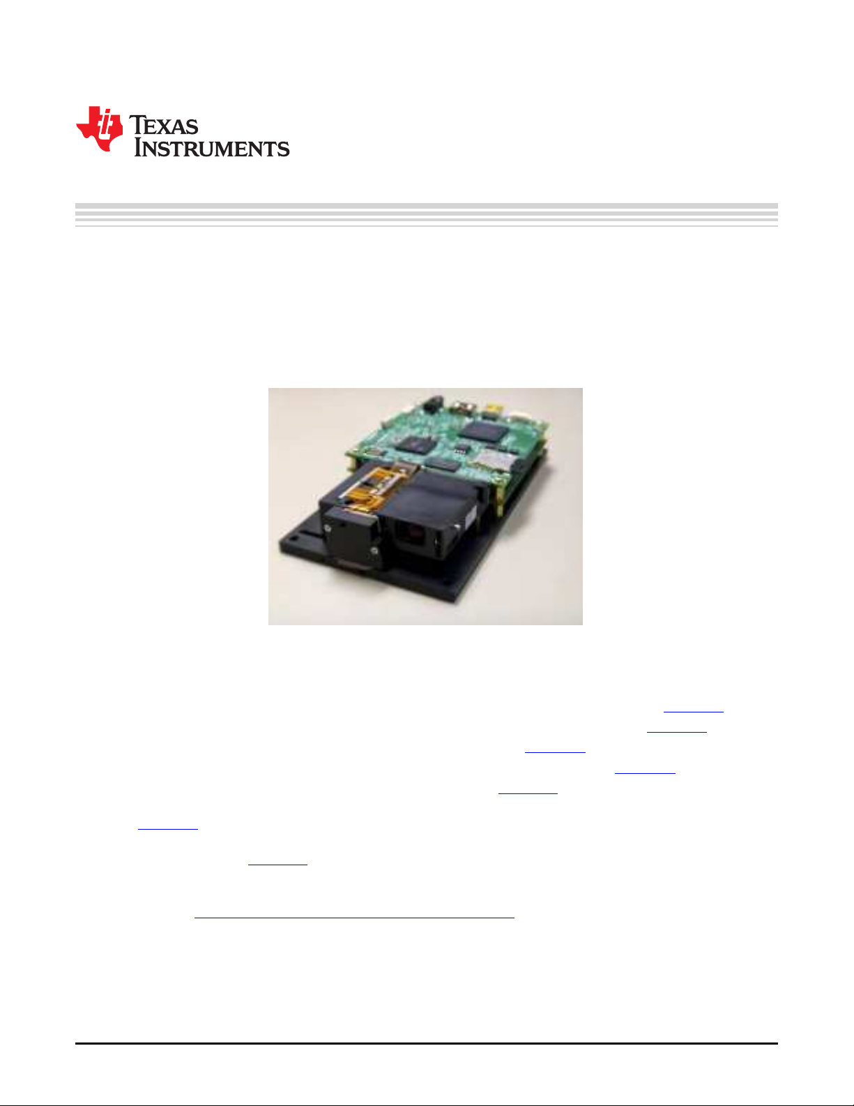
Figure 1. DLP LightCrafter Evaluation Module
Related Documentation from Texas Instruments
• DLPC300 data sheet: DLP Digital Controller for DLP3000 DMD, TI literature number DLPS023
• DLP3000 data sheet: DLP 0.3 WVGA DDR Series 220 DMD, TI literature number DLPS022
• DLPC300 Software Programmer’s Guide, TI literature number DLPU004
• DLP®LightCrafter™ DM365 Command Interface Guide, TI literature number DLPU007
• DLP®LightCrafter™ FPGA Overview TI literature number DLPA042
• Using the DLP®LightCrafter™ to Trigger CCD Cameras from The Image Source® TI literature number
DLPA032
• Creating Multiple Bit Depth and Multiple Color Pattern Sequences for DLP®LightCrafter™ Kit TI
literature number DLPA035
If You Need Assistance
Refer to the DLP and MEMS TI E2E Community support forums.
LightCrafter is a trademark of Texas Instruments.
DLP is a registered trademark of Texas Instruments.
DLPU006C–January 2012–Revised December 2013 Read This First
Submit Documentation Feedback
Copyright © 2012–2013, Texas Instruments Incorporated
7
Page 8

DLP®LightCrafter™ Module Overview
This chapter introduces the DLP LightCrafter module.
1.1 Welcome
Your new DLP LightCrafter module allows you to evaluate TI’s DLP 0.3-inch WVGA chipset platform along
with TI’s DaVinci Technology and the DM365 architecture.
This technology brings together a set of components providing an efficient and compelling system solution
for:
• Small display projector: embedded display, interactive display, information overlay
• Structured light applications: 3D modeling/design, biometric: fingerprint identification and face
recognition, machine vision and inspection
• Medical and life sciences: vascular imaging, dental impression scanner, intraoral dental scanners,
orthopaedics, prosthesis, CT/MRI/X-ray marking, retail cosmetics
1.2 What is in the LightCrafter EVM?
The DLP LightCrafter module consists of three subsystems:
• Light engine – includes the optics, red, green, and blue LEDs, and the 608 x 684 diamond pixel 0.3inch WVGA DMD. Capable of 20 lumens out-of-the-box with support to 50 lumens with user’s addition
of active cooling.
• Driver board – includes the LED driver circuits, DLPC300 DMD Controller, power management circuits,
and MSP430.
• System board – includes TMS320DM365, FPGA, and several connectors for external inputs.
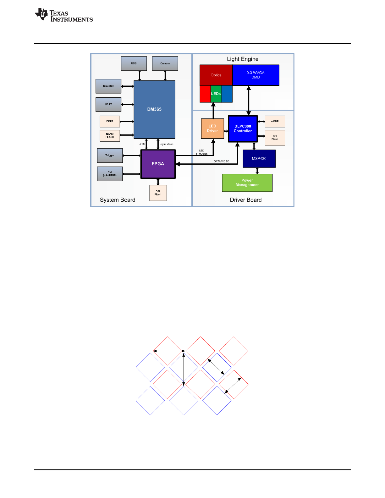
Figure 1-1 shows the major hardware components.
Chapter 1
DLPU006C–January 2012–Revised December 2013
8
DLP®LightCrafter™ Module Overview DLPU006C–January 2012–Revised December 2013
Copyright © 2012–2013, Texas Instruments Incorporated
Submit Documentation Feedback
Page 9
7 .6
3 7um
7
.
6
3
7
u
m
10.8 um
10 .8um
www.ti.com
What is in the LightCrafter EVM?
Figure 1-1. DLP LightCrafter Block Diagram
1.2.1 Light Engine
Young Optics, Inc. developed the DLP LightCrafter’s light engine. The light engine consists of the
following components:
• 0.3-inch WVGA DMD (DLP3000)
• OSRAM Red LED (LE A Q9WN)
• OSRAM Green LED (L CG H9RN)
• OSRAM Blue LED (LE B Q9WN)
• Murata NTC Thermistor (NCP15WF104F03RC)
• Optics with 1.66 Throw Ratio
The DLP3000 0.3-inch DMD contains 415872 mirrors arranged in a 608 by 684 with the diamond pattern
geometry shown in Figure 1-2
The DMD is vertically mounted at the end of the light engine. The light engine, including the LEDs and not
including the heat sinks, has a length of 39.3 mm, width of 41.6 mm, and height of 11 mm. Table 1-1 lists
the specifications of the light engine:
Figure 1-2. 0.3-inch DMD Pixel Geometry
DLPU006C–January 2012–Revised December 2013 DLP®LightCrafter™ Module Overview
Submit Documentation Feedback
Copyright © 2012–2013, Texas Instruments Incorporated
9
Page 10

What is in the LightCrafter EVM?
Table 1-1. DLP LightCrafter Light Engine Specifications
Brightness 25 at 1.85 W LED lm
Brightness uniformity (JBMA) 70 %
ANSI contrast 43:1
Full-on full-off contrast 685:1
Color uniformity (CIE x) 0.03
Color Uniformity (CIE y) 0.04
Throw ratio 1.66
Offset 100 %
Focus range 364 2169 mm
Image diagonal size 10 60 inch
Focus stroke 1 mm
The MSP430 monitors the light engine's thermistor to shutdown the EVM if excessive heat is measured on
the green LED. Passively cooled systems (no extra heat sinks or fans) have a thermal limit resulting in
LED currents under 633 mA. Actively cooled systems (extra heat sink and fan) have a thermal limit
resulting in LED currents under 1.5 A. Please see Table 2-1 for the corresponding LED current software
settings.
www.ti.com
MIN TYP MAX UNIT
10 at 0.6 W LED
30 at 2.25 W LED
1.2.2 Driver Board
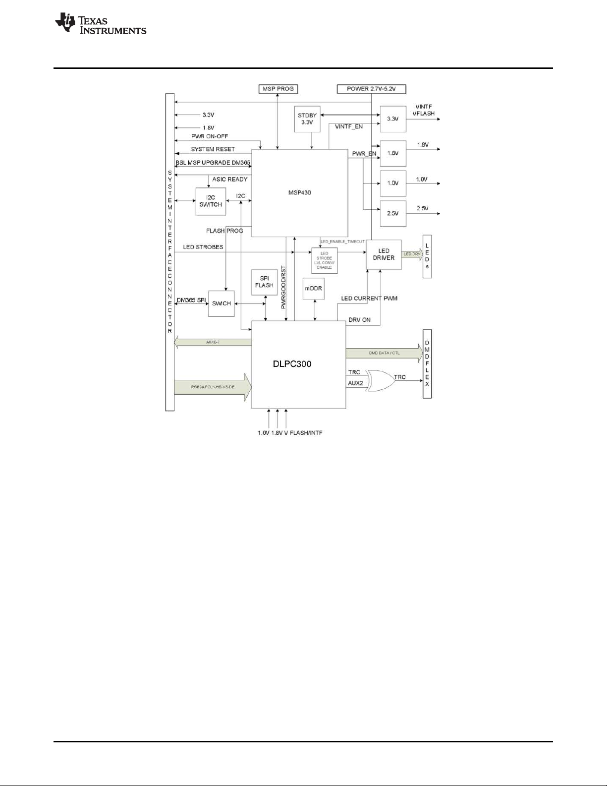
Figure 1-3 shows the DLP LightCrafter’s driver board block diagram.
10
DLP®LightCrafter™ Module Overview DLPU006C–January 2012–Revised December 2013
Copyright © 2012–2013, Texas Instruments Incorporated
Submit Documentation Feedback
Page 11
www.ti.com
What is in the LightCrafter EVM?
Figure 1-3. DLP LightCrafter Driver Board Block Diagram
The major components of the DLP LightCrafter’s driver board are:
• DLP3000: 0.3-inch WVGA chipset DMD
• DLPC300: 0.3-inch WVGA chipset controller for DLP3000 with:
– 2MB SPI FLASH that contains DLPC300 firmware
– 32MB mDDR that buffers images for the DLP3000
• MSP430:
– Controls power supply sequencing and system initialization
– Shuts down system upon detection of low or high input voltage
– Shuts down system if LED anode voltages exceed maximum limit
– Measures thermistor and shuts down system when maximum temperature ratings are exceeded
• LED driver circuitry
• Power management:
– TPS63020: Buck-Boost Regulator for LED supplies
– TPS63020: Buck-Boost Regulator for 3.3 V supply
– TPS62260: Step Down Converter for DLPC300 2.5 V supply
– TPS62400: Step Down Converter for DLPC300 1.0 V and 1.8 V supply
– TPS65120: 4-CH Bias for DMD VRST and VBIAS supplies
– TPS71501: LDO for DMD VOFS supply
DLPU006C–January 2012–Revised December 2013 DLP®LightCrafter™ Module Overview
Submit Documentation Feedback
Copyright © 2012–2013, Texas Instruments Incorporated
11
Page 12
What is in the LightCrafter EVM?
1.2.3 System Board
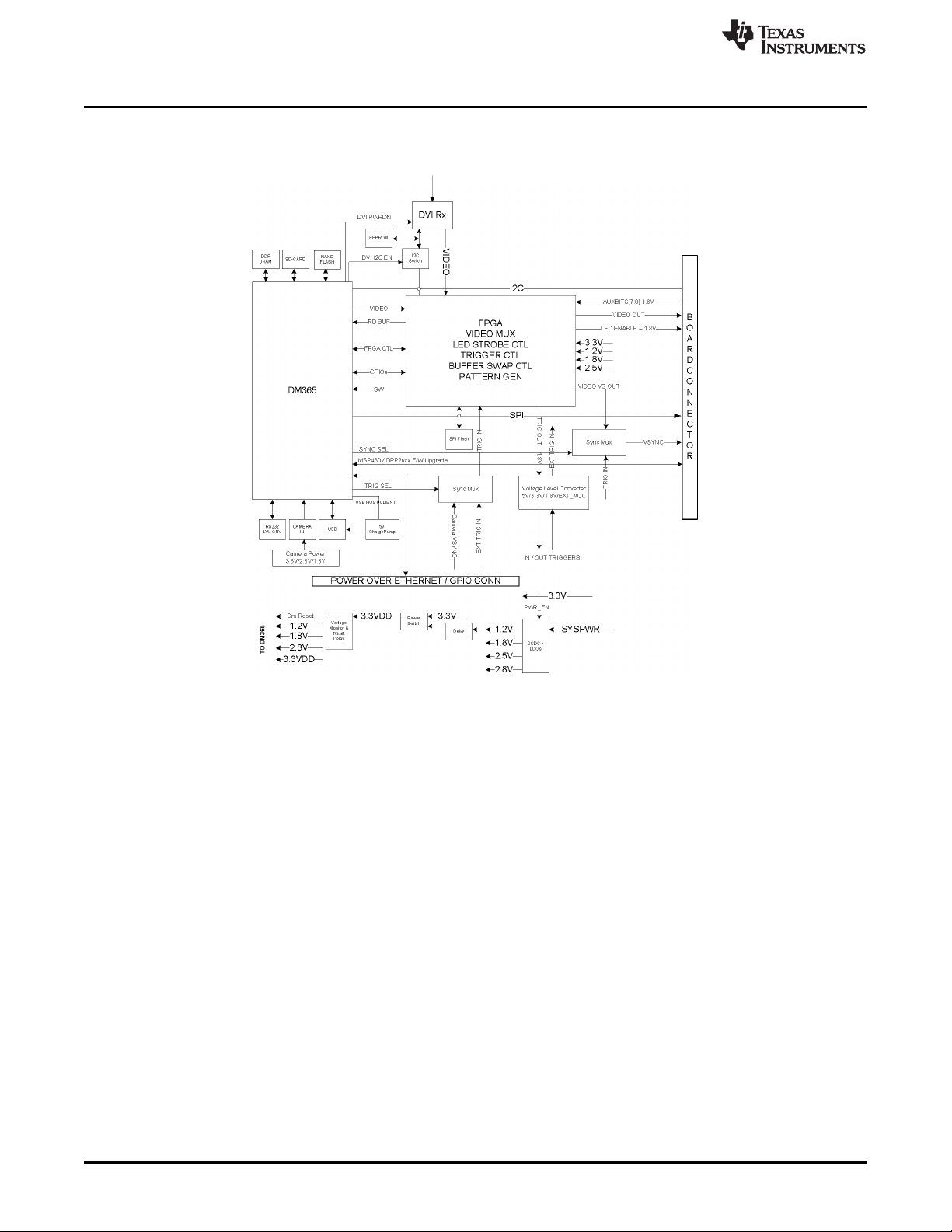
Figure 1-4 shows the DLP LightCrafter’s system board.
www.ti.com
Figure 1-4. DLP LightCrafter System Board Block Diagram
The major components of the system board are:
• Altera Cyclone IV FPGA:
– Controls video muxing (external miniHDMI or DM365)
– Controls LEDs enables
– Generates programmable camera triggers
– Manages four internal buffers for fast pattern display
• DM365: Embedded Linux main processor that controls camera interface, connectivity with PC, nonvolatile storage (Micro-SD and NAND Flash), FPGA control, video output, and video buffer in DDR2.
– 128MB DDR2 memory
– Micro-SD connector
– Mini-USB connector
– UART mini-plug
• MiniHDMI connector (DVI-D compliant)
• Power management:
– TPS650531: 2-Step Down Converter for FPGA’s and DM365’s 1.2 V and 1.8 V supplies with three
LDOs for FPGA’s 2.5-V supply and camera interface optional 2.8-V supply
12
DLP®LightCrafter™ Module Overview DLPU006C–January 2012–Revised December 2013
Copyright © 2012–2013, Texas Instruments Incorporated
Submit Documentation Feedback
Page 13
www.ti.com
1.3 DLP LightCrafter Embedded Software Overview
1.3.1 DM365 Software
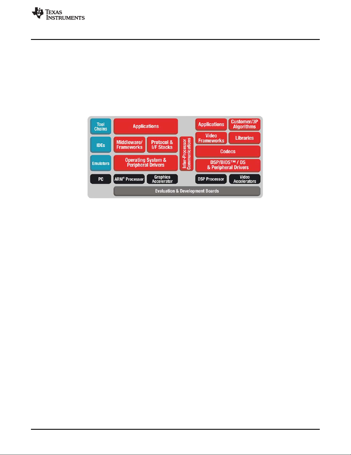
The DLP LightCrafter module software is based on TI’s DVSDK platform running on the Digital Media
System-on-Chip DM365. The DVSDK platform is a collection of royalty-free software components built
upon Linux operating system and pre-tested by TI. The software components include Linux kernel, Linux
filesystem, Linux product support package (PSP), application framework (APIs), codec libraries (MPEG4,
H.264, MPEG2, G.711, JPEG), example programs, DSP Codegen, and CodeSourcery tool chain with IDE
for cross-compiling and debugging target systems.
DLP LightCrafter Embedded Software Overview
Out of the box, the DLP LightCrafter boots from the on-board NAND FLASH. The DM365 acts as the main
processor of the system and boots as an embedded Linux device. The Linux file system resides on the
NAND or micro-SD card. Thus, the DLP LightCrafter does not require an NFS mount nor a TFTP server to
run. The embedded Linux system utilizes Remote Network Drivers Interface Specification (RNDIS) to send
packets through USB. DLP LightCrafter has a default IP address of 192.168.1.100.
1.3.1.1 Serial Communication
DLP LightCrafter’s UART port serves as a console output of the embedded Linux device. The DM365
sends error messages through the UART and accepts root level commands. A 2.5-mm stereo plug to
female DB9 connector is needed to connect the DLP LightCrafter’s UART port to a PC. For PCs with only
USB ports, use a USB-to-serial RS232 adapter.
To view UART console messages, configure a terminal emulator with the following parameters:
• Baud: 115200
• Data Bits: 8
• Stop Bits: 1
• Parity: None
• Flow Control: None
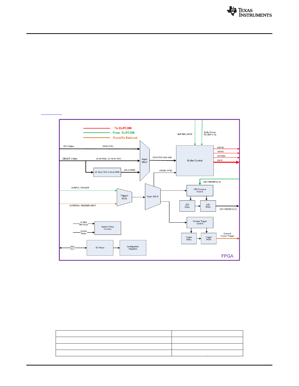
1.3.2 FPGA Overview
The FPGA expands the functionality of the DLP 0.3-inch WVGA chipset to enable the features of DLP
LightCrafter. An important feature of DLP LightCrafter is the ability to display stored patterns at high frame
rates. The FPGA provides the timing and signal management to implement a four buffer rotation scheme,
which enables a stored pattern capability of 4x24=96 binary patterns. Additional capabilities include:
• An external trigger input, which allows an external device to trigger stored patterns; configurable for
polarity (positive or negative), delay, and duration (pulse width).
• An external trigger output, which provides the ability to synchronize an external camera with the
display of patterns; configurable for polarity (positive or negative), delay, and duration (pulse width).
Figure 1-5. DM365 DVSDK Software Platform
DLPU006C–January 2012–Revised December 2013 DLP®LightCrafter™ Module Overview
Submit Documentation Feedback
Copyright © 2012–2013, Texas Instruments Incorporated
13
Page 14
DLP LightCrafter Embedded Software Overview
• A timing generator, which implements the internal auto trigger for continuously repeated pattern
display.
• Control for the illumination LEDs; generates LED strobe signals with configurable delay and duration to
set exposure; synchronized with the trigger.
• A video data source input selector (MUX); sends the video data to the DLPC300 parallel input. Inputs
are:
– Video from the TFP401A DVI receiver
– DM365 24-bit RGB (not bit identical with stored patterns)
– DM365 YUV4:2:2 video converted to RGB888 (bit identical with stored patterns).
• Timing and signal management for a "circular" frame buffer.
Please read the DLP LightCrafter FPGA Overview application note for more details. TI literature number
DLPA042 . Figure 1-6 shows the block diagram of the FPGA hardware.
www.ti.com
Figure 1-6. DLP LightCrafter FPGA Block Diagram
1.3.3 MSP430 Overview and Shutdown Protection Modes
The MSP430 controls the power sequencing, initializes the DLPC300, and provides safety shutdown
protection modes for DLP LightCrafter. The MSP430 has three shutdown protection modes. The shutdown
modes require that both the system power and USB cable be disconnected before a reboot is allowed.
Each mode is displayed by blinking the Red LED (D3) on the driver board at different rates. Table 1-2
describes the protection modes.
Table 1-2. DLP LightCrafter Protection Shutdown Modes
Shutdown Mode Description D3 On Time (s) D3 Off Time (s)
System voltage less than 3.9 V or greater than 5.5 V 5.0 0.5
LED anode voltage above 5.8 V 5.0 5.0
Light engine thermistor above 70°C 1.5 1.0
14
DLP®LightCrafter™ Module Overview DLPU006C–January 2012–Revised December 2013
Copyright © 2012–2013, Texas Instruments Incorporated
Submit Documentation Feedback
Page 15

www.ti.com
Other Items Needed for Operation
1.4 Other Items Needed for Operation
The DLP LightCrafter module is a flexible, ready to use EVM. However, DLP
LightCrafter EVM does not ship with any cables, power supply, or additional
hardware components. To use the EVM, you need:
• Power supply: center positive 5-V output with 2- to 3-A current rating and a
plug of 0.7 mm inner diameter x 2.35 mm outer diameter and 9.5-mm
female shaft.
• USB cable: A to mini-B
• RS232 cable with 2.5-mm stereo plug
1.5 DLP LightCrafter Connections
DLP LightCrafter offers the following connectivity options:
• Power Connector: supplies 5-V to DLP LightCrafter module
– Output: 5-V with 2- to 3-A current rating
– Inner plug diameter: 0.7 mm
– Outer diameter: 2.35 mm
– Female shaft length: 9.5 mm
– Positive center
• Mini-HDMI: supports external video input with 608 × 684 resolution at 60 Hz
• Micro-SD: tested to support up to 4GB, class 10, high capacity cards for
DM365 software and local data storage
• Mini USB: interfaces to PC as a slave device. A program running on the PC
issues commands to the DLP LightCrafter module
• Camera Connector: 28-pin connector using ITU-R BT.656 compatible
camera interface. The camera interface supports up to 12-bit data.
• Trigger connector: supports external or internally generated triggers for
camera capture
• Serial FLASH programming connectors:
– Driver board: programs the MSP430 FLASH and the DLPC300 serial
FLASH
– System board: programs the FPGA serial FLASH
• UART mini-plug: allows serial messages with the following RS-232
compatible serial configuration:
– 2.5-mm stereo plug: tip-RX, ring-TX, ground-GND
– Bits per second: 115200
– Data Bits: 8
– Parity: None
– Stops Bits: 1
– Flow Control: None
Figure 1-7 depicts the connectors and their respective locations.
DLPU006C–January 2012–Revised December 2013 DLP®LightCrafter™ Module Overview
Submit Documentation Feedback
Copyright © 2012–2013, Texas Instruments Incorporated
15
Page 16
1
2
3
4
5
7 8 9 10
15
17
6
12
13 14
16
11
DLP LightCrafter's Dimensions
www.ti.com
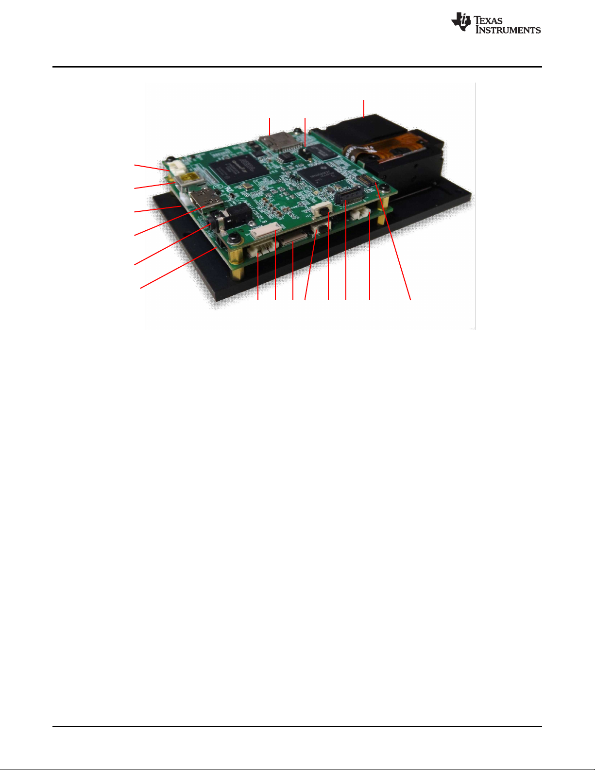
1. Trigger Input and Output
2. Mini USB
3. Power Connector
4. Mini HDMI
5. UART
6. Power Socket
7. I2C
8. FPGA SPI Flash Programming Interface
9. MSP430 or DLPC300 Flash Programming Interface
10. On or Off Button – Do not turn off while the Linux system is
booting
11. Input Selection Button (DM365, Internal Test Pattern, or HDMI
input)
12. Ethernet PHY
13. Fan
14. Camera
15. Focus Control
16. Boot Mode Selection Switch
17. Micro-SD card
Figure 1-7. DLP LightCrafter Connector Locations
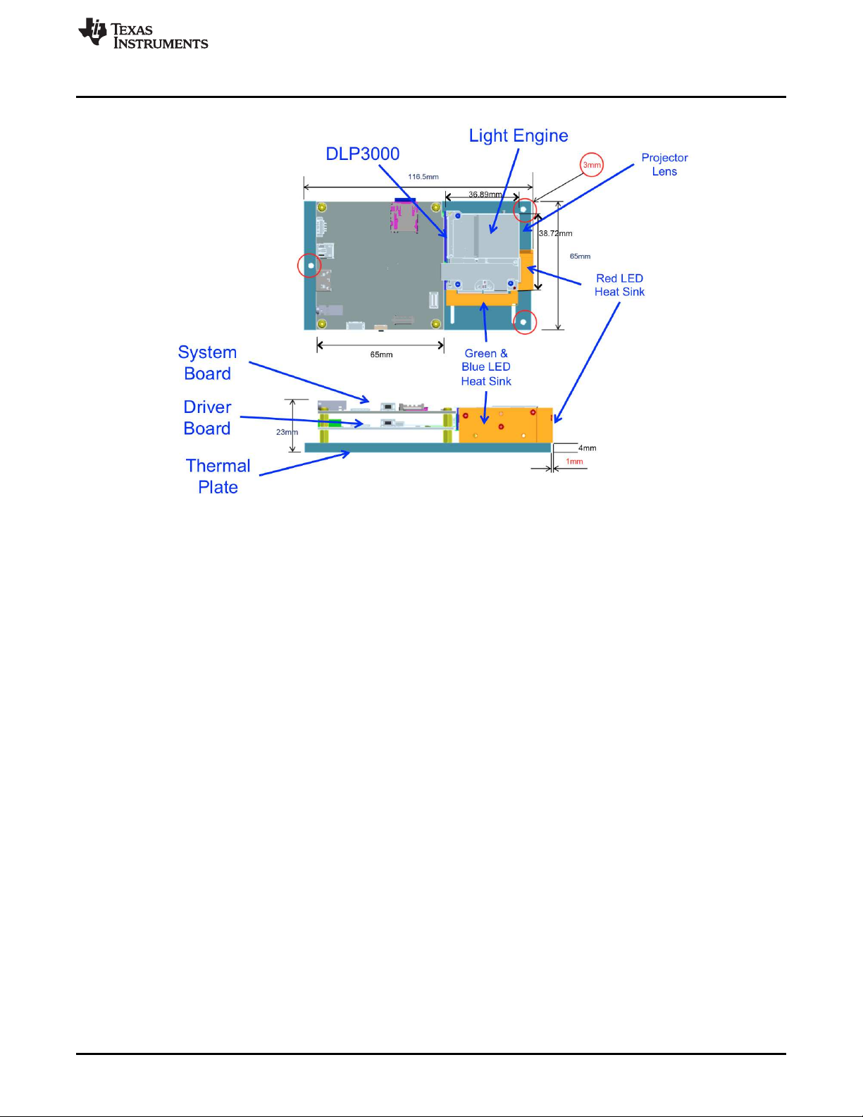
1.6 DLP LightCrafter's Dimensions
The DLP LightCrafter optical engine is mounted on top of a thermal plate to
provide passive cooling to the module. The DLP3000, 0.3-inch DMD, is
vertically mounted at the end of the optical engine and attached with a
connector to the driver board. The system board is mounted on top of the
driver board. This module has dimensions of 116.5-mm long, 65-mm wide, and
16
DLP®LightCrafter™ Module Overview DLPU006C–January 2012–Revised December 2013
23-mm tall. Figure 1-8 illustrates the DLP LightCrafter dimensions.
Copyright © 2012–2013, Texas Instruments Incorporated
Submit Documentation Feedback
Page 17
www.ti.com
DLP LightCrafter's Dimensions
Figure 1-8. DLP LightCrafter Module Dimensions
DLPU006C–January 2012–Revised December 2013 DLP®LightCrafter™ Module Overview
Submit Documentation Feedback
Copyright © 2012–2013, Texas Instruments Incorporated
17
Page 18

This chapter describes installing the Graphical User Interface (GUI), controlling the DLP LightCrafter
Module using the GUI, and upgrading the firmware on the EVM. All instructions relating to the GUI in this
document refer to the latest DLP LightCrafter GUI v5.0.
2.1 Installing the GUI
DLP LightCrafter includes a QT-based GUI to control the module through USB. QT is a Nokia crossplatform application and user interface framework with open source and commercial licenses. To install
the DLP LightCrafter GUI, follow these steps.
1. Download the most recent version of the DLP LightCrafter Software Bundle from
http://www.ti.com/tool/dlplightcrafter.
• Linux users will also need to install the latest QT version 5 library. Available from http://qt-
project.org/downloads. After the QT library has been installed, the user must create a file in the
"etc/ld.so.conf.d" directory so that the GUI coorrectly accesses the QT library. Create a file called
"Qt5.conf" in the "etc/ld.so.conf.d" directory and enter the location of the QT5 library directory. For
example, "<QtInstall_dir>/5.1.1/gcc/lib". Verify the actual directory path of the "lib" directory in the
installed QT5 library. After the file has been saved, run "ldconfig" in the terminal.
2. Extract the files from the downloaded zip file.
3. Run the DLP LightCrafter Software Bundle installer.
• Linux users may need to right click on the installer file and set a property to "Allow executing file as
program" so the installer executes correctly.
• Linux and Mac installers may attempt to install the software bundle to the root directoy, which for
some users may not be accessible. Choosing a different installation directory, such as the user's
home or documents folder should allow the installation to run properly.
4. From the GUI directory of the installed software, double click on the LightCrafterGUI application to run
the GUI. By default the GUI is installed in one of the following directories:
• Windows XP & 7: "C:\Texas Instruments-DLP\DLPLCRSoftwareBundle-3.0\LightCrafterGUI-v5.0-
Windows"
• Linux: ".../Texas Instruments-DLP/DLPLCRSoftwareBundle-3.0/LightCrafterGUI-v5.0-Linux"
– Linux users may need to right click on the GUI executable file and set a property to "Allow
executing file as program" so the GUI operates correctly.
• Mac: ".../Texas Instruments-DLP/DLPLCRSoftwareBundle-3.0/LightCrafterGUI-v5.0-Mac"
Chapter 2
DLPU006C–January 2012–Revised December 2013
Operating the DLP LightCrafter
2.2 Connecting to a PC
The DLP LightCrafter utilizes Remote Network Drivers Interface Specification (RNDIS) to send packets
through USB. Please read Section 2.2.1 or Section 2.2.2 to install the RNDIS drivers on Windows
systems. The drivers are already installed for Linux and Mac computers. Some Linux systems need to
have USB networking enabled.
After the RNDIS driver has been installed on the PC, please follow these steps to connect the DLP
LightCrafter. By default DLP LightCrafter's default IP address is "192.168.1.100," but this can be changed
to allow for multiple DLP LightCrafter's to connect to one computer. Please read Section 2.2.6 for more
details. To connect DLP LightCrafter to a PC, follow these steps:
1. Connect the DLP LightCrafter to the PC using a mini-USB cable.
18
Operating the DLP LightCrafter DLPU006C–January 2012–Revised December 2013
Copyright © 2012–2013, Texas Instruments Incorporated
Submit Documentation Feedback
Page 19
www.ti.com
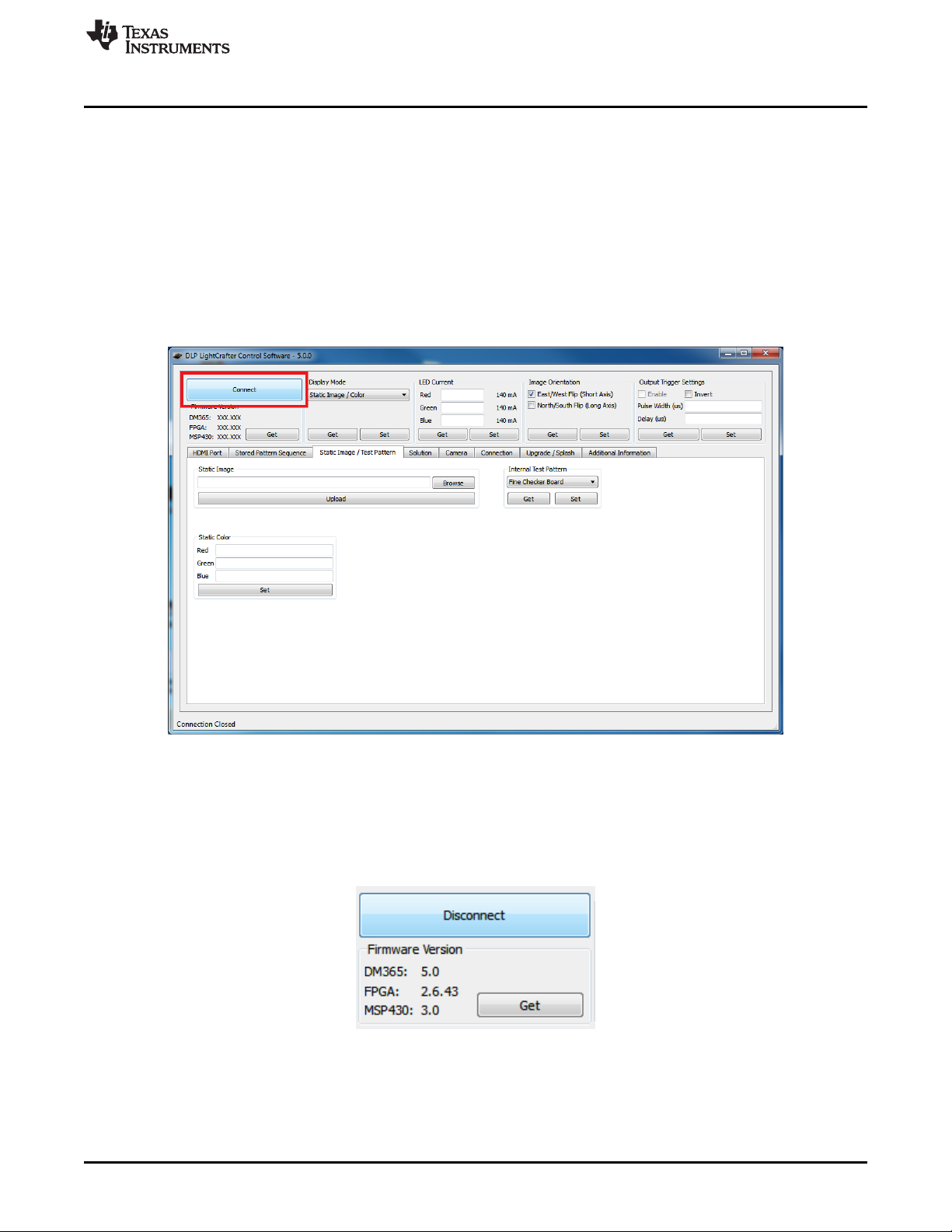
2. Turn on DLP LightCrafter using the On-Off switch. A new network using the RNDIS driver should
3. Open the DLP LightCrafter GUI.
4. Click the "Connect" button. See Figure 2-1.
Connecting to a PC
initialize.
• The network interface on Windows systems may take a couple minutes to initialize. Please read
Section 2.2.4 to speed up the initialization.
to speed up the initialization.
• The GUI connects to the IP address in the "Current IP Address" textbox from the "Connections"
tab. Please read Section 2.2.5 steps 7 and 8 for more details.
• After connecting, the GUI displays DLP LightCrafter's firmware versions. Select the correct tab,
according to the Display Mode, to update the GUI's tab settings to match the EVM's settings.
Figure 2-1. DLP LightCrafter GUI Connect Button
5. Click the "Disconnect" button before disconnecting the USB cable between DLP LightCrafter and the
computer. See Figure 2-2.
• The "Connect" button changes to the "Disconnect" button after a DLP LightCrafter connects.
• Unplugging the USB cable before disconnecting can cause problems when trying to reconnect to
the DLP LightCrafter if the device has not been shutdown.
Figure 2-2. DLP LightCrafter GUI Disconnect Button
DLPU006C–January 2012–Revised December 2013 Operating the DLP LightCrafter
Submit Documentation Feedback
Copyright © 2012–2013, Texas Instruments Incorporated
19
Page 20
Connecting to a PC
2.2.1 Installing the RNDIS Driver on Windows XP
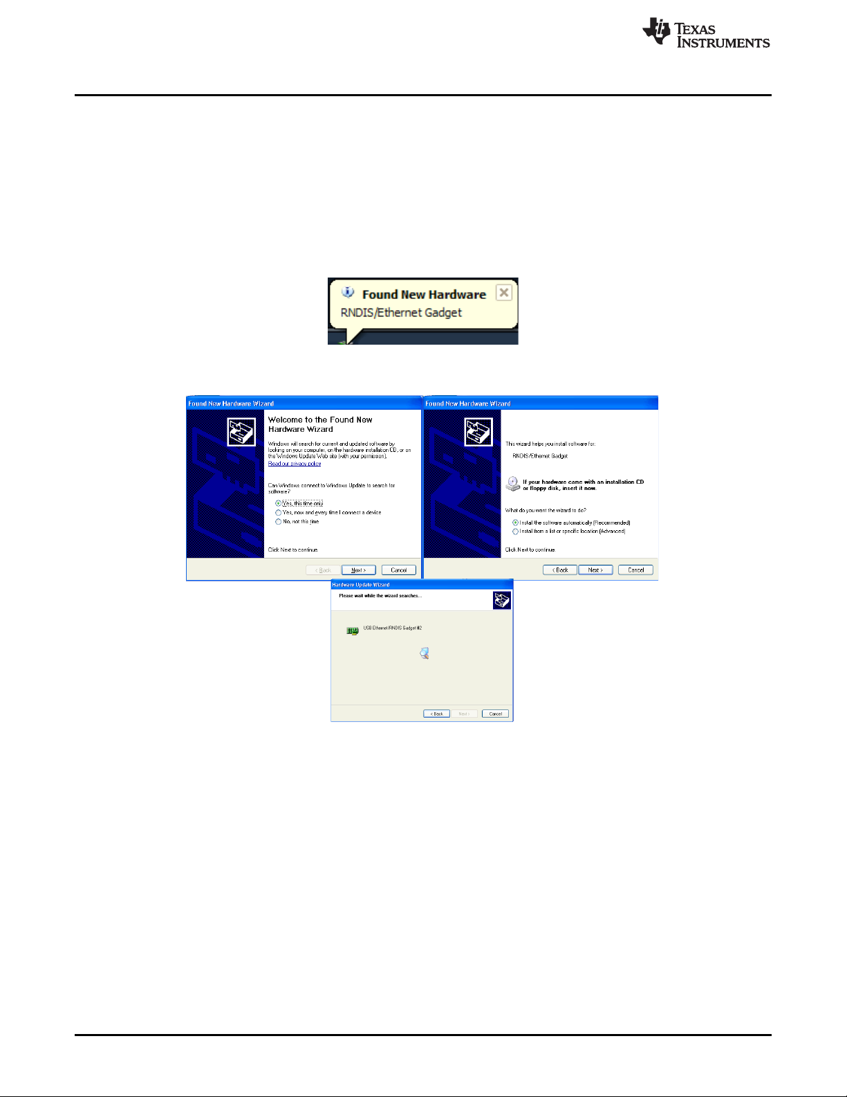
The first time DLP LightCrafter connects to Windows XP, a system pop-up window shows the new
"RNDIS/Ethernet Gadget" hardware device. Windows XP Service Pack 2 or greater includes the RNDIS
drivers, so these drivers should be found by the OS. Follow these steps to install the "RNDIS/Ethernet
Gadget" driver to enable USB communication with the EVM:
1. When the "Found New Hardware" dialog appears, as shown in Figure 2-3 and Figure 2-4, allow
Windows Update to search for the software.
2. Select “Install the software automatically (Recommended)” and click "Next." See Figure 2-4.
• The computer must have an active internet connection to download the driver.
Figure 2-3. Windows XP Found New Hardware Popup
www.ti.com
Figure 2-4. Windows XP Found New Hardware Wizard
2.2.2 Installing the RNDIS Driver on Windows 7
The first time DLP LightCrafter is connected on Windows 7 systems a pop-up window appears stating that
a new hardware device called a "RNDIS/Ethernet Gadget" was found. Follow these steps to install the
"RNDIS/Ethernet Gadget" driver to enable USB communication with the EVM:
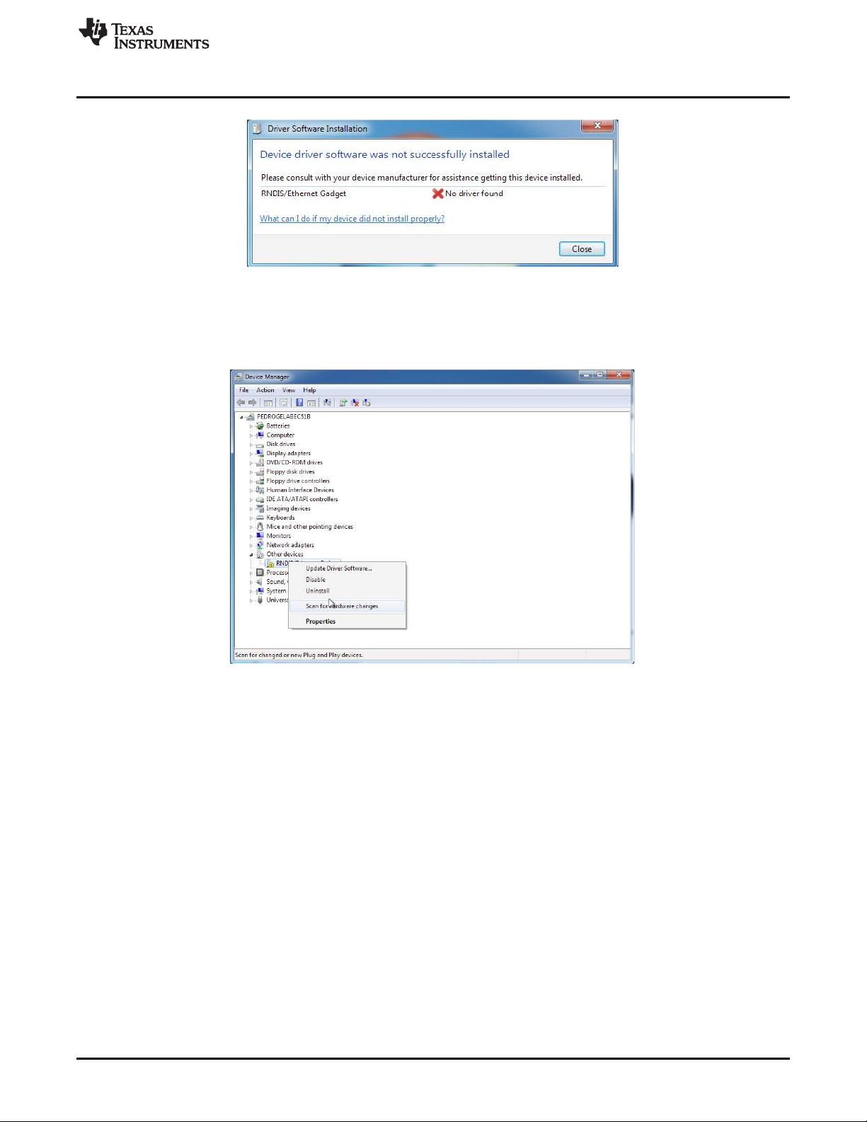
1. The "Driver Software Installation" dialog should appear. Windows 7 will try to automatically download
the driver and fail. A message indicating that the “device driver software was not successfully installed"
is displayed. See Figure 2-5
20
Operating the DLP LightCrafter DLPU006C–January 2012–Revised December 2013
Copyright © 2012–2013, Texas Instruments Incorporated
Submit Documentation Feedback
Page 21
www.ti.com
2. Right click on “My Computer” and open the Device Manager.
3. Expand Other Devices. Right click on “RNDIS/Ethernet Gadget” and select “Update Driver Software.”
Connecting to a PC
Figure 2-5. Windows 7 Driver Software Installation Window
See Figure 2-6.
Figure 2-6. Windows 7 Device Manager Window
4. Select “Browse my computer for driver software” from the “Update Driver Software” window. See
Figure 2-7.
DLPU006C–January 2012–Revised December 2013 Operating the DLP LightCrafter
Submit Documentation Feedback
Copyright © 2012–2013, Texas Instruments Incorporated
21
Page 22

Connecting to a PC
5. On the next dialog, select “Let me pick from a list of device drivers on my computer.”
6. Select "Network Adapter." See Figure 2-8.
www.ti.com
Figure 2-7. Windows 7 Update Driver Software Search or Browse Window
22
Figure 2-8. Windows 7 Update Driver Software Select Device Window
7. Select "Microsoft Corporation" as the manufacturer and “Remote NDIS Compatible Device” as the
network adapter. Click "Next." See Figure 2-9.
Operating the DLP LightCrafter DLPU006C–January 2012–Revised December 2013
Copyright © 2012–2013, Texas Instruments Incorporated
Submit Documentation Feedback
Page 23

www.ti.com
8. Click "Close" after the software updates. See Figure 2-10.
Connecting to a PC
Figure 2-9. Windows 7 Update Driver Software Select Network Driver Window
Figure 2-10. Windows 7 Update Driver Software Successfully Updated Window
2.2.3 Enabling the RNDIS Driver on Linux
DLP LightCrafter connects to Linux systems as a Linux-USB Ethernet/RNDIS device. Some systems
require USB networking support to be manually enabled. To enable USB networking follow these steps:
1. Open a command terminal.
2. Open the "/etc/network/interfaces" file in superuser mode. See Figure 2-11.
• For example, "sudo gedit /etc/network/interfaces"
3. Add "iface usb0 inet dhcp" to the file. See Figure 2-11.
DLPU006C–January 2012–Revised December 2013 Operating the DLP LightCrafter
Submit Documentation Feedback
Copyright © 2012–2013, Texas Instruments Incorporated
23
Page 24

Connecting to a PC
4. Save the file.
5. Reboot the Linux system and run "ifconfig." See Figure 2-12.
• If "usb0" is not present, continue to step 6.
www.ti.com
Figure 2-11. Ubuntu Command Terminal and "interfaces" File
24
Figure 2-12. Ubuntu Command Terminal "ifconfig" Result Before USB Setup
6. Setup usb0 with IP address. See Figure 2-13.
• For example, "sudo ifconfig usb0 192.168.1.99 up"
• Choose an IP address different than the address of the LightCrafter.
7. Check that usb0 was properly assigned an IP address using "ifconfig." See Figure 2-13.
Operating the DLP LightCrafter DLPU006C–January 2012–Revised December 2013
Copyright © 2012–2013, Texas Instruments Incorporated
Submit Documentation Feedback
Page 25

www.ti.com
Figure 2-13. Ubuntu Command Terminal "ifconfig" Result After USB Setup
2.2.4 Fixing the USB Start-Up Delay in Windows
When DLP LightCrafter is first connected to a Windows system, the Local Area Connection created
automatically obtains an IP address. This "Identifying..." process for the Local Area Connection can take
over a minute on some systems. To decrease the time required for DLP LightCrafter to connect, the Local
Area Network assigned an IP address allowing the computer to connect to the EVM within seconds after
fully booting. Follow these steps to assign an IP address for the Local Area Connection:
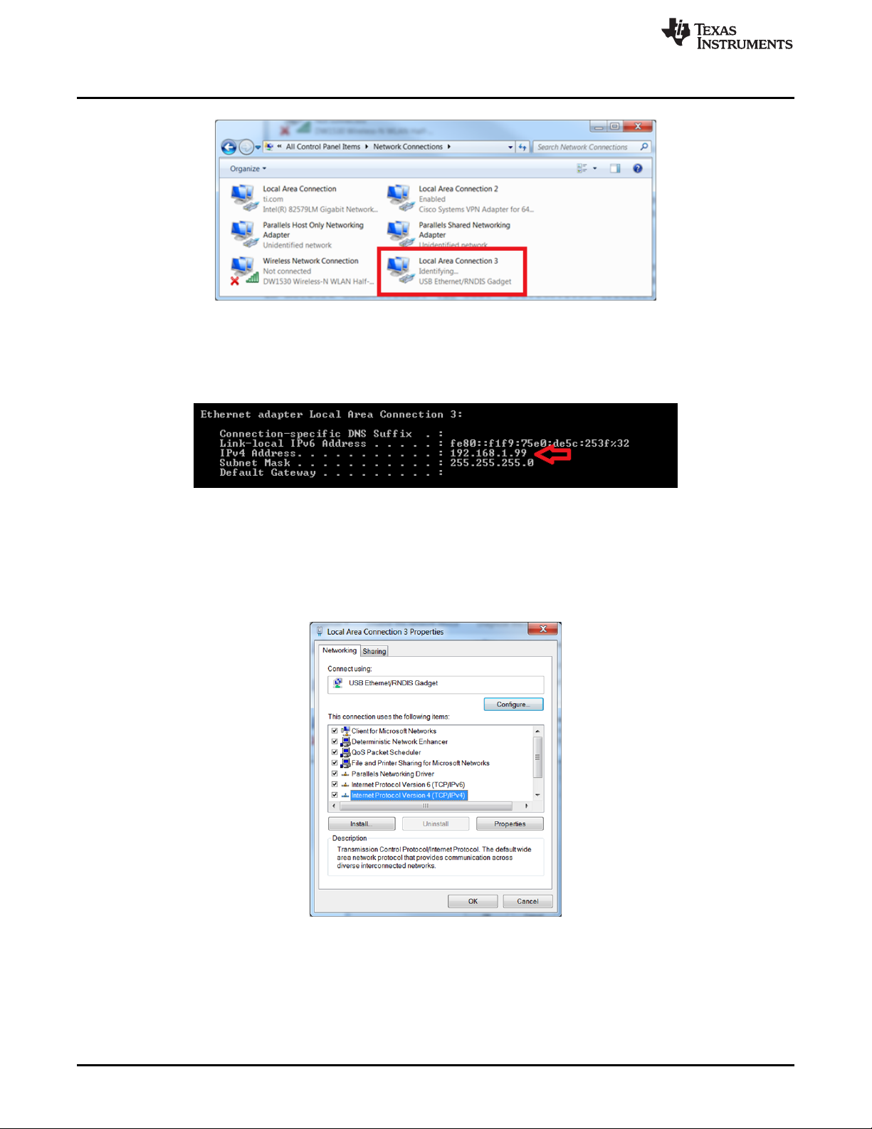
1. Open the Control Panel and type "Network Connections" into the search bar.
2. Select "View Network Connections." See Figure 2-14.
Connecting to a PC
Figure 2-14. Windows 7 Network Connections Window
3. Connect DLP LightCrafter to the computer via a mini-USB cable.
4. Power on DLP LightCrafter. While it boots, a new Local Area Connection in your Network Connections
will appear.
5. Wait until the LAN connection stops "Identifying" or "Acquiring" a network address. See Figure 2-15.
DLPU006C–January 2012–Revised December 2013 Operating the DLP LightCrafter
Submit Documentation Feedback
Copyright © 2012–2013, Texas Instruments Incorporated
25
Page 26
Connecting to a PC
Figure 2-15. Windows 7 Network Connections Identifying Local Area Connection
6. Open a cmd terminal and run "ipconfig /all"
7. A list of all connections will be displayed. Find the IPv4 address and Subnet Mask of DLP
LightCrafter's Local Area Connection. See Figure 2-16.
www.ti.com
Figure 2-16. Windows 7 Command Window Local Area Connection IPv4 Address
8. From the Network Connections window, right click on DLP LightCrafter's Local Area Connection and
click "Properties"
9. In the box "This connection uses the following items" under the Networking tab, look for “Internet
Protocol Version 4”. Highlight the item by clicking on it and then click “Properties” underneath the box.
See Figure 2-17.
26
Figure 2-17. Windows 7 Local Area Connection Properties
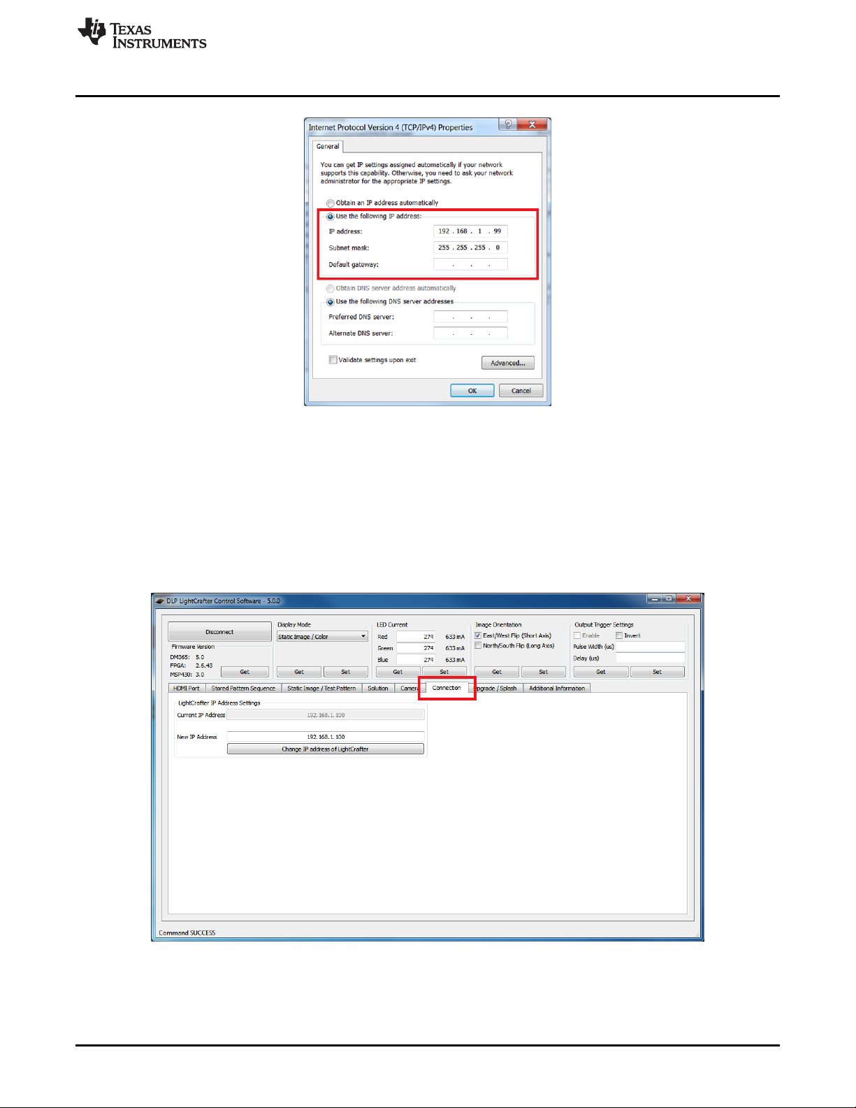
10. Choose "Use the following IP address"
11. Enter the IPv4 address and Subnet Mask found from step 7. See Figure 2-18.
• Please note that each connected device and USB port requires a unique IP address for its Local
Area Connection.
Operating the DLP LightCrafter DLPU006C–January 2012–Revised December 2013
Copyright © 2012–2013, Texas Instruments Incorporated
Submit Documentation Feedback
Page 27
www.ti.com
12. Click "OK" to exit the IPv4 Properties
13. Click "OK" to exit the LAN connection properties.
Connecting to a PC
Figure 2-18. Windows 7 Local Area Connection TCP/IPv4 Properties
2.2.5 Changing the DLP LightCrafter's IP Address
To change DLP LightCrafter's IP address, follow these steps:
1. Connect DLP LightCrafter GUI to EVM.
2. Select the "Connections" tab. See Figure 2-19.
Figure 2-19. DLP LightCrafter GUI Connection Tab
3. Change the last three digits of the IP address in the "New IP Address" textbox. See Figure 2-20.
• For example: Change "192.168.1.100" to "192.168.1.106"
• Even IP addresses are recommended to prevent IP Address conflicts between the computer's
DLPU006C–January 2012–Revised December 2013 Operating the DLP LightCrafter
Submit Documentation Feedback
Copyright © 2012–2013, Texas Instruments Incorporated
27
Page 28

Connecting to a PC
Local Area Connection and DLP LightCrafter.
4. Click the "Change IP address of LightCrafter" button.
5. A popup window, as shown in Figure 2-21, will ask "Do you want to change the IP of the LightCrafter?"
Click "Yes."
6. Restart the EVM using the On/Off button on the Driver board, by powering the device off and back on.
• The GUI will disconnect from DLP LightCrafter automatically.
• The "Current IP Address" textbox will not be updated until the EVM has been reconnected.
7. After DLP LightCrafter has restarted and the network has initialized, select the "Connection" tab.
8. Type DLP LightCrafter's new IP address into the "Current IP Address" textbox. See Figure 2-22.
• This setting cannot be modified while the GUI is connected to an EVM.
www.ti.com
Figure 2-20. DLP LightCrafter GUI Connection New IP Address Textbox
Figure 2-21. DLP LightCrafter GUI Changing IP Popup
Figure 2-22. DLP LightCrafter GUI Connection Current IP Address Textbox
9. Click the "Connect" button.
2.2.6 Connecting Multiple DLP LightCrafter's to One PC
By changing DLP LightCrafter's IP address, it is possible to control multiple EVMs from a single computer.
Follow these steps to control multiple DLP LightCrafter's from a single computer:
1. Connect one DLP LightCrafter to the computer with a USB cable.
2. Follow the steps in Section 2.2.5 to set a unique IP addresses for the connected EVM.
3. Disconnect and turn off the EVM.
4. Repeat steps 1-3 for each DLP LightCrafter.
5. After all DLP LightCrafter's have unique IP addresses, start an instance of the DLP LightCrafter GUI for
each EVM
• For example: If three DLP LightCrafters will be connected, there should be three GUI windows
running.
6. For each open GUI window, follow steps 7 to 9 in Section 2.2.5 to connect each DLP LightCrafter,
using their unique IP address, to the open GUI windows.
28
Operating the DLP LightCrafter DLPU006C–January 2012–Revised December 2013
Copyright © 2012–2013, Texas Instruments Incorporated
Submit Documentation Feedback
Page 29
www.ti.com
2.3 Selecting the Display Mode
The DLP LightCrafter has four display modes: Static Image/Color, Test Patterns, HDMI Port, and Stored
Pattern Sequence. To upload static 24-bit RGB images or project a single color read section Section 2.9.
To use the internally generated test patterns, read Section 2.10. To stream 24-bit RGB video through the
HDMI port read Section 2.7. To create a pattern sequence using external patterns from the HDMI port,
read Section 2.8.2. To create a pattern sequence using stored patterns, read Section 2.8.1. See Figure 2-
23.
Selecting the Display Mode
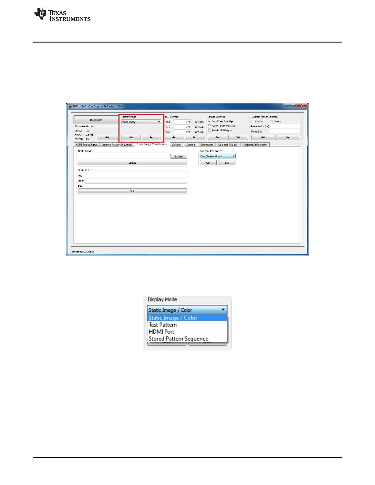
Figure 2-23. DLP LightCrafter GUI Display Mode Setting
To change the display mode, follow these steps:
1. Click and select the desired display mode from the drop down options as shown in Figure 2-24.
Figure 2-24. DLP LightCrafter GUI Display Mode Options
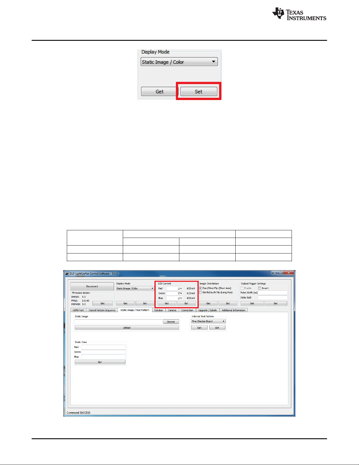
2. Click the "Set" button as shown in Figure 2-25.
• The GUI automatically changes to the correct tab and updates the GUI settings in that tab to
match the EVM's settings if the display mode is properly set.
• The resolution, active pixels, and active lines are reset to their default value if the display mode
changes from "HDMI Port" to "Stored Pattern Sequence".
• When the display mode changes, the "Start Vector" and "Num of Vectors" reset to 0.
DLPU006C–January 2012–Revised December 2013 Operating the DLP LightCrafter
Submit Documentation Feedback
Copyright © 2012–2013, Texas Instruments Incorporated
29
Page 30
Setting the LED Current
Figure 2-25. DLP LightCrafter GUI Display Mode Set Button
3. To retrieve the EVM's display mode, click the "Get" button.
• The GUI will automatically change to the correct tab and update the GUI settings in that tab to
match the EVM's settings.
2.4 Setting the LED Current
The DLP LightCrafter uses current drivers to individually control the current through each LED using an
integer current value. The LED current is computed as follows:
LED Current (mA) = 1.8 × (LED Current Value) + 140 (1)
When at room temperature, the maximum value allowed is dependent on the cooling system of the DLP
LightCrafter. The passively cooled systems of the DLP LightCrafter (no extra heat sinks or fans) have a
thermal limit resulting in LED currents under 633 mA. DLP LightCrafter actively cooled systems (extra heat
sink and fan) have a thermal limit resulting in LED currents under 1.5 A. Table 2-1 summarizes these
constraints. Figure 2-26 shows the "LED Current" settings in the GUI.
www.ti.com
Table 2-1. LED Current Settings
DLP LightCrafter LED CURRENT VALUE LED CURRENT
COOLING SYSTEM
Passively cooled 1 274 633 mA
Actively cooled 1 758 1.5 A
MIN MAX MAX
30
Figure 2-26. DLP LightCrafter GUI LED Current Settings
Operating the DLP LightCrafter DLPU006C–January 2012–Revised December 2013
Copyright © 2012–2013, Texas Instruments Incorporated
Submit Documentation Feedback
Page 31
www.ti.com
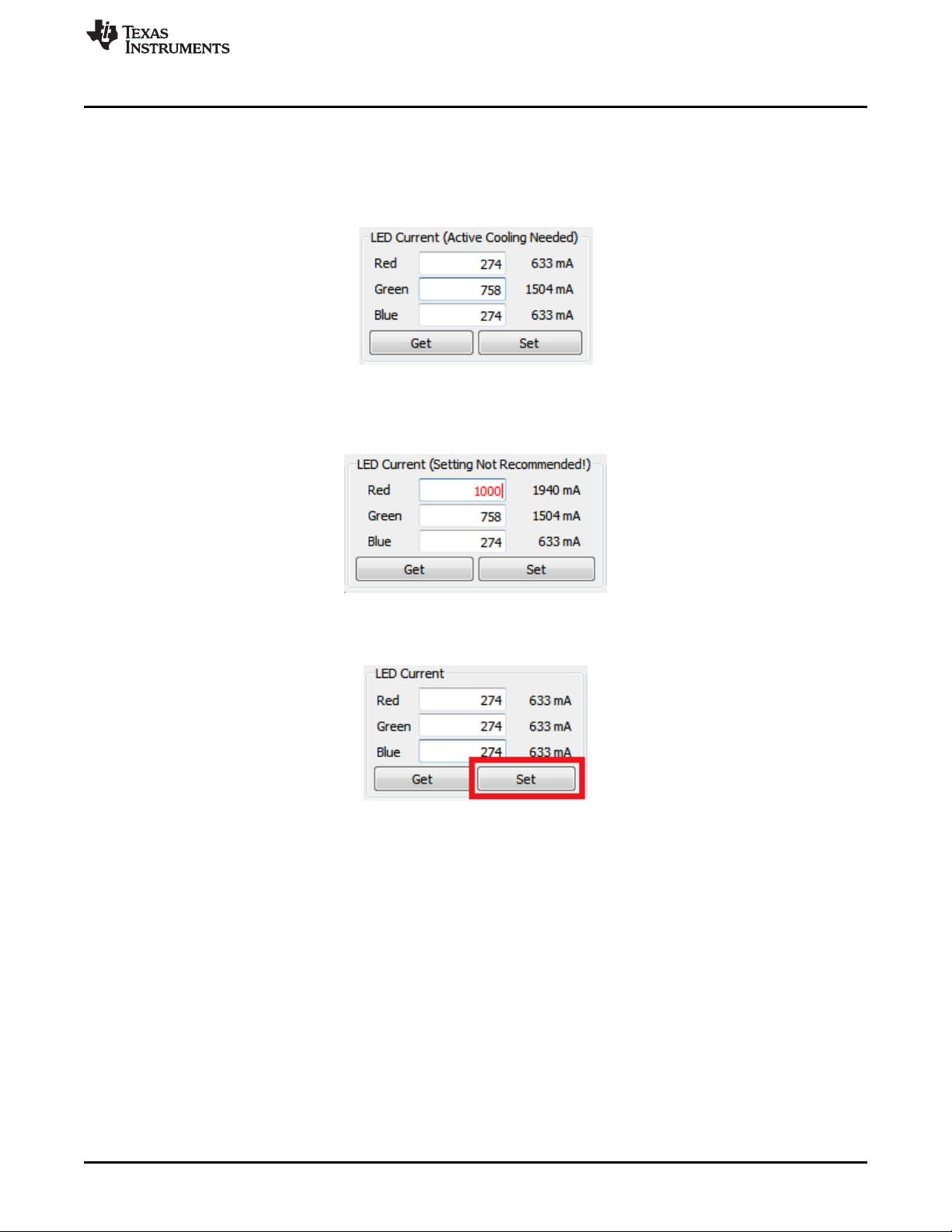
To change the DLP LightCrafter LED current follow these steps:
1. Type the LED Current Value into the corresponding LED's textbox. The GUI automatically calculates
Controlling Image Orientation
and displays the LED current in mA.
• If the value is above 274, a note is added to the LED Current title to inform the user that active
cooling is needed. See Figure 2-27.
Figure 2-27. DLP LightCrafter GUI LED Current Setting Active Cooling Needed
• If the value is above 758, the value turns red and a note is added to the LED Current title to inform
the user that this is not a recommended setting. See Figure 2-28.
Figure 2-28. DLP LightCrafter GUI LED Current Setting Not Recommended
2. Click the "Set" button as shown in Figure 2-29.
Figure 2-29. DLP LightCrafter GUI LED Current Setting Set Button
3. To retreive the EVM's current LED Current Value, click the "Get" button.
2.5 Controlling Image Orientation
The Image Orientation controls the long- and short-axis flips to support front, rear, table, and ceiling
mounted projection. The Image Orientation takes place after the "Set" button has been clicked. Figure 2-
30 shows the "Image Orientation" settings in the GUI.
• East/West Flip (Short-Axis): If checked, the image is flipped along the east/west axis of the projected
image. Normal table front projection has this setting checked (otherwise, the image is flipped
horizontally).
• North/South Flip (Long-Axis): If checked, the image is flipped along the north/south axis of the
projected image. Normal table front projection has this setting unchecked (otherwise, the image is
flipped vertically).
DLPU006C–January 2012–Revised December 2013 Operating the DLP LightCrafter
Submit Documentation Feedback
Copyright © 2012–2013, Texas Instruments Incorporated
31
Page 32

Triggering External Peripherals (Camera and So Forth)
Figure 2-30. DLP LightCrafter GUI Image Orientation Settings
www.ti.com
2.6 Triggering External Peripherals (Camera and So Forth)
The DLP LightCrafter features a trigger output on connecter J7 to allow cameras and other peripherals to
be in sync with the EVM. The trigger output is an open drain type with a 10 kΩ internal pull-up resistor.
This works well with cameras accepting a standard TTL level trigger input. Some cameras with global
trigger capability require a minor hardware change on the DLP LightCrafter system board in order to
function correctly. For more information, read Using the DLP® LightCrafter™ to Trigger CCD Cameras
from The Image Source®, TI literature number DLPA032. Figure 2-31 shows the "Output Trigger Settings"
in the GUI.
32
Operating the DLP LightCrafter DLPU006C–January 2012–Revised December 2013
Copyright © 2012–2013, Texas Instruments Incorporated
Submit Documentation Feedback
Page 33

www.ti.com
Triggering External Peripherals (Camera and So Forth)
Figure 2-31. DLP LightCrafter GUI Output Trigger Settings
To setup the output Trigger, follow these steps:
1. Check the "Enable" checkbox in the Output Trigger Settings as shown in Figure 2-32.
• The output trigger can only be enabled if the EVM is in either "Stored Pattern Sequence" mode or
"External Streaming Pattern Sequence" while in "HDMI Port" mode.
Figure 2-32. DLP LightCrafter GUI Output Trigger Enable Checkbox
2. If an active low trigger output is desired, check the "Invert" checkbox. If an active high trigger output is
desired do not check "Invert"
3. Enter the pulse width and delay in microseconds
• Pulse Width: width of trigger output pulse in microseconds
• Delay: number of microseconds pulse is delayed after pattern exposure begins
4. Click "Set" as shown in Figure 2-33.
Figure 2-33. DLP LightCrafter GUI Output Trigger Set Button
DLPU006C–January 2012–Revised December 2013 Operating the DLP LightCrafter
Submit Documentation Feedback
Copyright © 2012–2013, Texas Instruments Incorporated
33
Page 34

Streaming 24-bit RGB Video from the HDMI Port
5. To retrieve DLP LightCrafter's current output trigger settings, click the "Get" button
2.7 Streaming 24-bit RGB Video from the HDMI Port
DLP LightCrafter can operate as a DVI-D compliant projector with its mini-HDMI connector. By default, the
EVM has the 608 x 684 EDID software installed, and supports resolutions listed in Table 2-2.
Table 2-2. Supported Resolutions for Video Input
240x320 640x480 480x852 864x480
320x240 480x720 852x480 720x240
240x427 720x480 480x853 720x288
427x240 480x752 853x480 360x640
430x640 752x480 480x853 640x360
640x430 480x800 854x480 854x480
480x640 800x480 480x854 608x684
To stream 24-bit RGB video, follow these steps:
1. Connect an active HDMI source to the mini HDMI connector.
2. Set Display Mode to “HDMI Port.”
3. Select "RGB Video Streaming (24 bits per pixel)" as shown in Figure 2-34.
www.ti.com
(1)
Figure 2-34. DLP LightCrafter GUI RGB Video Streaming Selected on HDMI Port Tab
4. Select the frame rate.
5. Enter one of the resolutions listed in Table 2-2.
6. If the full frame is desired:
• Set Active Pixels Start to 0
• Set Active Pixels Width to the resolution width entered in step 5
• Set Active Lines Start to 0
• Set Active Lines Height to the resolution height entered in step 5
7. Click the “Set” button as shown in Figure 2-35.
(1)
The video input port is DVI-D compliant, but not HDMI compliant.
34
Operating the DLP LightCrafter DLPU006C–January 2012–Revised December 2013
Copyright © 2012–2013, Texas Instruments Incorporated
Submit Documentation Feedback
Page 35

www.ti.com
8. To retrieve the EVM's current video mode settings, click the "Get" button.
Creating Pattern Sequences
Figure 2-35. DLP LightCrafter GUI RGB Video Streaming Set Button
2.8 Creating Pattern Sequences
The DLP LightCrafter can perform external and internal pattern sequences. External sequences use
streaming patterns from the mini-HDMI port. Internal sequences use preloaded patterns and can be stored
on the LightCrafter with solutions for reuse. The following sections describe how to setup pattern
sequences on DLP LightCrafter.
2.8.1 Internal Stored Pattern Sequences
To create an internal pattern sequence follow these steps:
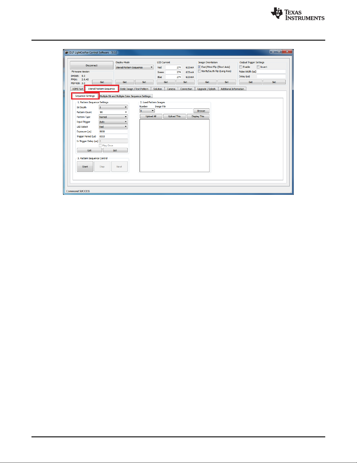
1. Set the display mode as "Stored Pattern Sequence".
2. Select the "Stored Pattern Sequence", then the "Sequence Settings" tab as shown in Figure 2-36.
DLPU006C–January 2012–Revised December 2013 Operating the DLP LightCrafter
Submit Documentation Feedback
Copyright © 2012–2013, Texas Instruments Incorporated
35
Page 36
Creating Pattern Sequences
Figure 2-36. DLP LightCrafter GUI Sequence Settings Tab in Stored Pattern Sequence Tab
www.ti.com
3. Set Pattern settings by updating the following parameters inside the Pattern Setting box:
• Bit Depth: bit depth of the image. Allowed values are from 1 to 8.
• Pattern Count: amount of patterns to display in sequence. Allowed values 1 to 96 divided by the bit
depth. For example, if the bit depth is 8, the maximum amount of patterns is 96 / 8 = 12. If the bit
depth is 1, the maximum amount of patterns is 96/1 = 96.
• Pattern Type
– Normal: display the pattern sequence. Available for all bit depths.
– Inverted: display the pattern sequence with each pattern followed by its inverted pattern.
Available for pattern sequences with Bit Depth equal to 1.
– HW Pattern: display a pattern sequence created from hardwired (HW) patterns. See
Section 2.8.1.1 for more details.
• Trigger Type: selects how the patterns are triggered.
– Auto: patterns displayed after end of Trigger Period.
– Command: patterns displayed when the Next button is pressed.
– External (Positive): patterns displayed after an external active high trigger signal.
– External (Negative):patterns display after an external active low trigger signal.
• LED Select: selects which color LED is active (Red, Green, or Blue). See Section 2.8.1.2 for
details about using the "Multiple" setting.
• Trigger Delay: number of microseconds delay after trigger is received and pattern is displayed.
See Figure 2-37.
• Exposure Time: number of microseconds the pattern is displayed. Input 0 to display the pattern
through the whole trigger period. See Figure 2-37.
• Trigger Period: number of microseconds delay between two consecutive patterns. See Figure 2-
37.
36
Operating the DLP LightCrafter DLPU006C–January 2012–Revised December 2013
Copyright © 2012–2013, Texas Instruments Incorporated
Submit Documentation Feedback
Page 37

www.ti.com
4. Click the "Set" button as shown in Figure 2-38.
Creating Pattern Sequences
Figure 2-37. Relationship between Trigger Period, Trigger Delay, and Exposure Time
• If the exposure or trigger period values are less than the minimum allowed, DLP LightCrafter
automatically sets the minimum values.
Figure 2-38. DLP LightCrafter GUI Pattern Sequence Settings Set Button
NOTE: Changing the bit-depth, exposure, or pattern count requires that all the images need to be
uploaded again. Uploading all images is necessary since the pattern arrangement in the
frame memory buffer depends on these settings.
5. Click the "Browse" button to select the number of bitmap patterns matching the bit depth and number
previously set. See Figure 2-39 and Figure 2-40.
• The pattern number should be set to 0.
• The patterns must be a BMP file with a resolution of 608 by 684.
• The pattern file names should have their corresponding pattern numbers within the name (that is
00_PAT, 01_PAT, 02_PAT, and so forth)
– Each file should have the same number of digits for the pattern number
• Correct: 00_PAT, 01_PAT, 02_PAT, ... , 10_PAT, and so forth
• Wrong: 0_PAT, 1_PAT, 2_PAT, ... , 10_PAT, and so forth
• Click the pattern number drop down list to view the pattern in the GUI. This selected pattern can
then be displayed on the EVM by clicking "Display This" button.
DLPU006C–January 2012–Revised December 2013 Operating the DLP LightCrafter
Submit Documentation Feedback
Copyright © 2012–2013, Texas Instruments Incorporated
37
Page 38

Creating Pattern Sequences
www.ti.com
Figure 2-39. DLP LightCrafter GUI Load Pattern Images
Figure 2-40. DLP LightCrafter GUI Select Images Window
6. Upload the patterns to DLP LightCrafter by clicking the "Upload All" button as shown in Figure 2-41.
38
Operating the DLP LightCrafter DLPU006C–January 2012–Revised December 2013
Copyright © 2012–2013, Texas Instruments Incorporated
Submit Documentation Feedback
Page 39

www.ti.com
Creating Pattern Sequences
Figure 2-41. DLP LightCrafter GUI Upload All Pattern Images Button
7. Start the pattern sequence by clicking "Start" as shown in Figure 2-42.
Figure 2-42. DLP LightCrafter GUI Pattern Sequence Control Start Button
2.8.1.1 Hardwired Pattern Sequences
The DLPC300 can generate a set of 15 vertical 1-bit monochrome patterns with its internal pattern
generator. These patterns are called hardwired patterns in the DLP LightCrafter GUI. Up to 32 of these
vertical patterns can be arranged in any order with or without inversion. The inversion of a pattern
converts the black regions to white and the white regions to black. For a description of the available
patterns, see Table 2-64 from the DLPC300 Programmer’s Guide, TI literature number DLPU004. Pattern
numbers 0 through 10 form a set of gray coded patterns. Pattern numbers 11 through 14 can be used for
auto-focus.
The extended pattern sequence mode follows the same steps as those listed in Section 2.8.1 for regular
internal stored pattern sequences except for selecting the images. Rather than clicking the "Browse"
button, select the desired HW Pattern from the drop-down list. See Figure 2-43.
DLPU006C–January 2012–Revised December 2013 Operating the DLP LightCrafter
Submit Documentation Feedback
Copyright © 2012–2013, Texas Instruments Incorporated
39
Page 40

Creating Pattern Sequences
Figure 2-43. DLP LightCrafter GUI Hardwired Pattern Sequence Settings and Pattern Selection
www.ti.com
NOTE: While the DLP LightCrafter internally generates hardwired patterns, the "Upload All" button
still needs to be clicked after all hardwired patterns have been selected for each pattern.
2.8.1.2 Multiple Bit-Depth and Multiple Color Pattern Sequences
With the latest FPGA Firmware (version 2.6.43) and DM365 software (version 4 or above), the DLP
LightCrafter can run internal pattern sequences that use multiple bit depths and multiple colors (MBMC).
To create an MBMC pattern sequence, follow these steps:
1. Submit MBMC pattern sequence requests on TI's E2E forum in the DLP LightCrafter Development
Platform subsection (http://e2e.ti.com/) by creating a post titled "MBMC Request" and provide the
following information:
• Pattern Exposure time (250 µs < PExT ≤ 20000 µs).
– This parameter influences the maximum bit-depth possible in the sequence for each pattern.
For example, if the exposure time is 1000 µs then it is only possible to have 1-bit or 2-bit depth
patterns. On the other hand, an exposure time ≥ 8333 µs supports patterns of all bit-depths
from 1 to 8. See Table 4-3 to find the minimum exposure time for each pattern’s bit-depth.
• Patterns Sequence Information as shown in Table 2-3.
– Patterns must be listed in the order to be displayed.
– Depending on the order of patterns with different bit-depths it is possible that there will be
unused bit-planes that still count towards the maximum 96 bit-planes. The system will not allow
split multiple bit-depth patterns across the 24-bit frame buffer boundaries. For example, in the
1st row of Table 2-3, there are five, 5bpp patterns. This would translate to 5 x 5 = 25 individual
bit planes, but each frame buffer can only accommodate 24 individual binary frames. Therefore,
in a pattern sequence of five, 5-bit patterns, 20 reside in the first frame buffer, while the last 5bit plans reside in the next frame buffer. The 5bpp x 5 pattern set actually consumes 29
individual bit planes of the frame buffer:
• 5bpp × 4 patterns + 4 unused patterns = 24 patterns (from the first frame buffer)
• 5bpp × 1 pattern = 5 patterns (from the second frame buffer)
• Results in 24 + 5 = 29 individual binary patterns.
40
Operating the DLP LightCrafter DLPU006C–January 2012–Revised December 2013
Copyright © 2012–2013, Texas Instruments Incorporated
Submit Documentation Feedback
Page 41

Trigger Input
Auto/External/Camera
Pattern Display
8333 Secμ
MBMC Pattern Sequence:
1bppX1R_2bppX1G_3bppX1B_4bppX1R_5bppX1G_6bppX1B_7bppX1R_8bppX1G_83333 Secμ
1-Bit 2-Bit 3-Bit 4-Bit 5-Bit 6-Bit 7-Bit 8-Bit 1-Bit 2-Bit
MBMC Pattern Sequence
www.ti.com
Creating Pattern Sequences
Table 2-3. MBMC Pattern Sequence Information Input
Pattern Pattern Color
Bit-Depth (Red/Green/Blue)
5 5 Blue
1 6 Red
.. .. …
.. .. …
7 2 Green
1 3 Blue
Number of Patterns
• Pattern Sequence Equation in the following form:
– <pattern_bit-depth>X<num_of_patterns><color (R)ed or (G)reen or (B)lue>_<pattern_bit-
depth>X<num_of_patterns><color (R)ed or (G)reen or (B)lue>_.....<pattern_bit-
depth>X<num_of_patterns><color (R)ed or (G)reen or (B)lue>_<exposure_time>µs
– For example,
1bppX1G_2bppX1G_3bppX1G_4bppX1G_5bppX1G_6bppX1G_7bppX1G_8bppX1G_8333µs
• The development time frame of the project (optional)
• A description of the application and the need for this capability (optional)
DLPU006C–January 2012–Revised December 2013 Operating the DLP LightCrafter
Submit Documentation Feedback
Figure 2-44. MBMC Pattern Sequence Output Example
2. Prepare image list file.
• Create a TXT file.
• Add one BMP image filename per line.
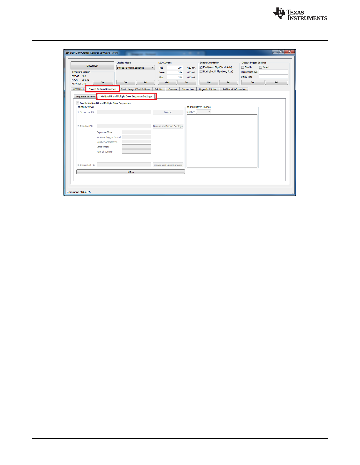
3. Set Display mode to "Stored Pattern Sequence."
4. Select "Stored Pattern Sequence" tab and "Multiple Bit and Multiple Color Sequence Settings" tabs.
See Figure 2-45.
Copyright © 2012–2013, Texas Instruments Incorporated
41
Page 42
Creating Pattern Sequences
Figure 2-45. DLP LightCrafter GUI Multiple Bit and Multiple Color Sequence Settings Tab in Stored
Pattern Sequence Tab
www.ti.com
5. Check the "Enable Multiple Bit and Multiple Color Sequences" checkbox. See Figure 2-46.
• This disables several settings in the "Sequence Settings" tab and requires that a readme file be
imported
6. Browse and select the "Sequence File" (.BIN).
7. Browse and Import the settings from the "Readme File" (.TXT)
• The GUI automatically imports all the necessary values from the readme file into the GUI
8. Browse for the "Image List File" and import the images.
• The GUI automatically parses the images listed in the file into 1bpp patterns and loads them into
the GUI. This means that the "Browse" button in the "Sequence Settings" tab does not need to be
used.
• The GUI displays the MBMC patterns as the DLP LightCrafter will project in the "MBMC Pattern
Images" in the "Multiple Bit and Multiple Color Sequence Settings" tab.
42
Operating the DLP LightCrafter DLPU006C–January 2012–Revised December 2013
Copyright © 2012–2013, Texas Instruments Incorporated
Submit Documentation Feedback
Page 43

www.ti.com
Creating Pattern Sequences
Figure 2-46. DLP LightCrafter GUI Multiple Bit and Multiple Color Sequence Settings Tab in Stored
Pattern Sequence Tab
9. Select "Sequence Settings" tab. See Figure 2-47.
10. Click the sequence settings "Set" button.
11. Click "Upload All" button.
12. Click "Start".
Figure 2-47. DLP LightCrafter GUI Example Sequence Settings for MBMC Sequence
DLPU006C–January 2012–Revised December 2013 Operating the DLP LightCrafter
Submit Documentation Feedback
Copyright © 2012–2013, Texas Instruments Incorporated
43
Page 44

Creating Pattern Sequences
2.8.2 External Pattern Sequences Streaming from HDMI Port
To create an external pattern sequence follow these steps:
1. Set the display mode as "HDMI Port".
2. Select "External Streaming Pattern Sequence" in the "HDMI Port" tab. See Figure 2-48.
3. Set the LED Select.
4. Set the Color Bit Depth.
5. Set the Frame Rate.
6. Click "Set."
• The GUI calculates the patterns per frame and pattern rate from the bit depth and frame rate.
• The resolution in "External Streaming Pattern Sequence" mode cannot be changed. The video
stream must supply frames with a 608 × 684 pixel resolution.
www.ti.com
Figure 2-48. DLP LightCrafter GUI External Streaming Pattern Sequence Settings in HDMI Port Tab
2.8.3 Extended Pattern Sequences
In addition to the high-speed internal stored pattern sequences, DLP LightCrafter can run extended
pattern sequences that allows more than 96 patterns and exposure times up to 5 seconds.
some constraints to the extended pattern sequence mode:
• Sequences with more than 96 patterns:
– Maximum of 1050 patterns for 1-bit per pixel patterns
– Maximum of 131 patterns for 8-bit per pixel patterns
• Longer exposures than 20 ms:
– Maximum exposure of 5 second for 8-bit per pixel patterns
– Maximum exposure of 2 second for 1-bit per pixel patterns
• Minimum trigger period of 18 ms
• Minimum exposure of 5 ms
• "Play Once" not supported
• A 330 µs dark frame occurs every 20 ms
• "Multiple Bit and Multiple Color" mode not supported
(1)
Multiple bit and multiple color pattern sequences are not enabled in extended pattern sequence mode.
44
Operating the DLP LightCrafter DLPU006C–January 2012–Revised December 2013
Copyright © 2012–2013, Texas Instruments Incorporated
Submit Documentation Feedback
(1)
There are
Page 45

www.ti.com
• Resistor R205 must be installed on system boards from DLP LightCrafter hardware prior to revision
2.0.
• FPGA Firmware must be version 2.4.39 or newer
The extended pattern sequence mode follows the same steps as those listed in Section 2.8.1 for regular
internal stored pattern sequences except for selecting the pattern count. Type in the pattern count instead
of selecting an item from the drop-down list.
2.9 Uploading Static Images or Colors
To upload a 608 × 684 pixel 24-bit RGB Windows bit-mapped image (*.BMP) or display a static color,
follow these steps:
1. Set Display Mode to “Static Image / Color.”
2. Select “Static Image / Test Pattern” tab. See Figure 2-49.
Uploading Static Images or Colors
Figure 2-49. DLP LightCrafter GUI Static Image and Test Pattern Tab
3. To display a 608 × 684 pixel 24-bit RGB image, click the “Browse” button to select the BMP file and
then click the "Upload" button. See Figure 2-50.
Figure 2-50. DLP LightCrafter GUI Static Image Upload Button
4. To display a solid color enter an 8-bit value (0 to 255) for each color in the Static Color settings and
click "Set." See Figure 2-51.
• For each LED, 0 corresponds to total darkness and 255 to maximum brightness according to the
LED's current setting.
DLPU006C–January 2012–Revised December 2013 Operating the DLP LightCrafter
Submit Documentation Feedback
Copyright © 2012–2013, Texas Instruments Incorporated
45
Page 46

Using Test Patterns
Figure 2-51. DLP LightCrafter GUI Static Color Set Button
2.10 Using Test Patterns
To display DLPC300 internal test patterns, follow these steps:
1. Set Display Mode to “Test Pattern.”
2. Select “Static Image / Test Pattern” tab as shown in Figure 2-49.
3. Pull down the menu under “Internal Test Pattern” and select the desired option. The options are:
• Fine Checker Board
• Solid Black
• Solid White
• Solid Blue
• Solid Red
• Vertical Lines
• Horizontal Lines
• Vertical Lines (Fine)
• Horizontal Lines (Fine)
• Diagonal Lines
• Vertical Gray Ramp
• Horizontal Gray Ramp
• ANSI 4 × 4 Checker Board
4. Click on the “Set” button to display the selected pattern. See Figure 2-52.
www.ti.com
Figure 2-52. DLP LightCrafter GUI Internal Test Pattern Settings
2.11 Saving and Loading Solutions
Any of DLP LightCrafter's current settings can be stored as a solution. This solution can later be recalled
or set to run as the default solution which starts after booting. To create a solution, follow these steps:
1. Set the appropriate settings such as LED Current, Pattern Sequence bit depth, number of patterns,
input trigger, trigger period, exposure, time, display mode, and so forth.
2. Click on "Solution" tab as shown in Figure 2-53.
3. Type in the solution name and click “Save.”
4. To manage stored solutions, use the following buttons:
• Load: load the selected solution
46
Operating the DLP LightCrafter DLPU006C–January 2012–Revised December 2013
Copyright © 2012–2013, Texas Instruments Incorporated
Submit Documentation Feedback
Page 47

www.ti.com
Capturing Images using the Camera Connector
• Default: sets the selected solution as the default solution when DLP LightCrafter boots; in the list,
this solution will be colored blue
• Delete: erases the currently selected solution
• Refresh: lists stored solutions
Figure 2-53. DLP LightCrafter GUI Solution Tab
2.12 Capturing Images using the Camera Connector
The DLP LightCrafter's embedded Linux system comes with the MT9P031 camera sensor driver. By
connecting this sensor to camera connector (item 14 in Figure 1-7) the EVM can capture images from the
sensor and send the image to the computer or to the DMD. For details about the connector, see
Section 5.2. The camera must be connected to DLP LightCrafter before the EVM boots to ensure the
sensor is detected.
To capture an image from the sensor and save the image to the PC, follow these steps:
1. Select the "Camera" tab as shown in Figure 2-54.
2. Click the "Capture" button.
3. Click the "Save" button.
4. To capture an image from the sensor and send the image to the DMD, click the "Preview" button.
DLPU006C–January 2012–Revised December 2013 Operating the DLP LightCrafter
Submit Documentation Feedback
Copyright © 2012–2013, Texas Instruments Incorporated
47
Page 48

Upgrading Firmware
www.ti.com
Figure 2-54. DLP LightCrafter GUI Camera Tab
2.13 Upgrading Firmware
Periodic upgrades to the firmware of the FPGA, DLPC300, MSP430, and EDID are accomplished through
the DLP LightCrafter GUI. To upgrade the DM365 firmware, a micro-SD card with the new software is
needed to load the software into the NAND flash.
2.13.1 Updating the MSP430, FPGA, DLPC300, or EDID using the GUI
To upgrade the FPGA, DLPC300, MSP430, or EDID, perform the following steps:
1. Select the "Solution / Splash" and "Firmware Upgrades" tabs as shown in Figure 2-55.
48
Operating the DLP LightCrafter DLPU006C–January 2012–Revised December 2013
Copyright © 2012–2013, Texas Instruments Incorporated
Submit Documentation Feedback
Page 49
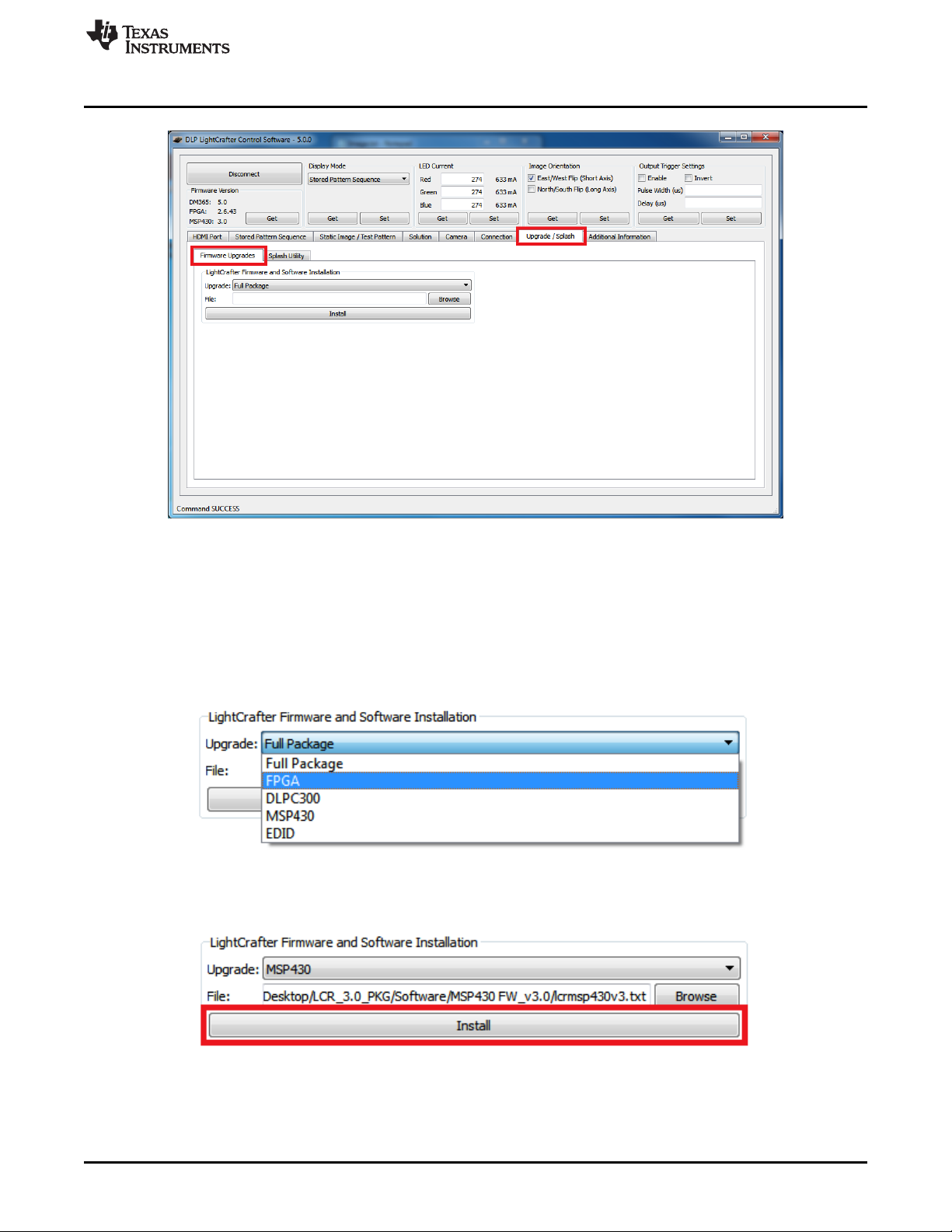
www.ti.com
Upgrading Firmware
Figure 2-55. DLP LightCrafter GUI Firmware Upgrade Tab
2. Select which firmware to upgrade and then click the “Browse” button as shown in Figure 2-56.
• To upgrade MSP430 firmware, select a TI-tagged file (*.txt).
• To upgrade FPGA, select an “*.rbf” file.
• To upgrade DLPC300 firmware, select a binary file (*.bin).
• To upgrade EDID, select a binary file (*.bin).
– Read Section 2.7 for setting the video mode parameters.
Figure 2-56. DLP LightCrafter GUI Firmware Select Drop-Down Options
3. After the file is selected, click Install as shown in Figure 2-57.
Figure 2-57. DLP LightCrafter GUI Firmware Install Button
DLPU006C–January 2012–Revised December 2013 Operating the DLP LightCrafter
Submit Documentation Feedback
Copyright © 2012–2013, Texas Instruments Incorporated
49
Page 50

Upgrading Firmware
2.13.2 Updating the DM365 Firmware
The DM365 linux system can be loaded from either the NAND flash or SD card. To upgrade the linux
system on the NAND, the linux file system must be copied from an SD card into the NAND. Before the file
system can be installed into NAND or booted from the SD card, the linux file system must be copied to an
SD card. For instructions on how to setup the SD card, see Section 2.13.2.1 or Section 2.13.2.2. After the
SD card has been setup, see Section 2.13.2.3 to install the file system into NAND or Section 2.13.2.4 to
boot from the SD card.
NOTE: Updating DLP LightCrafter's DM3654 firmware removes all stored solutions from the EVM.
TI does not recommend using SDHC cards for firmware upgrades. For a list of
tested SD cards, visit
http://processors.wiki.ti.com/index.php/SD_card_boot_and_flashing_tool_for_D
M355_and_DM365
2.13.2.1 Setting up the SD Card on Windows
To setup the SD card on a Windows systems, follow these steps:
1. Insert micro-SD card into PC
2. Right click on the SD card from My Computer as shown in Figure 2-58 and select "Format..."
www.ti.com
CAUTION
50
Figure 2-58. Windows 7 SD Card Right-Click Menu
3. Select "FAT32 (Default)" as the file system and use the default values for the other settings. See
Figure 2-59.
4. Click the "Start" button.
Operating the DLP LightCrafter DLPU006C–January 2012–Revised December 2013
Copyright © 2012–2013, Texas Instruments Incorporated
Submit Documentation Feedback
Page 51

www.ti.com
Upgrading Firmware
Figure 2-59. Winodws 7 Format SD Card Window
5. Run the "Windows Command Processor" as an administrator. See Figure 2-60.
DLPU006C–January 2012–Revised December 2013 Operating the DLP LightCrafter
Submit Documentation Feedback
Copyright © 2012–2013, Texas Instruments Incorporated
51
Page 52

Upgrading Firmware
www.ti.com
52
Figure 2-60. Windows 7 Run cmd.exe Right-click Menu
6. Change to the directory with the DM365 firmware (*.dat) and lcr_boot_sd.exe using the "cd" command.
See Figure 2-61.
7. In the "Windows Command Processor" run lcr_boot_sd.exe {DM365 firmware file} E: for a SD card
mapped to the E: drive.
• To create a bootable SD card, use the dm3xx_sdv*.dat firmware
• To create a SD card to flash the DLP LightCrafter NAND, use the dm3xx_nandv*.dat firmware
Operating the DLP LightCrafter DLPU006C–January 2012–Revised December 2013
Copyright © 2012–2013, Texas Instruments Incorporated
Submit Documentation Feedback
Page 53
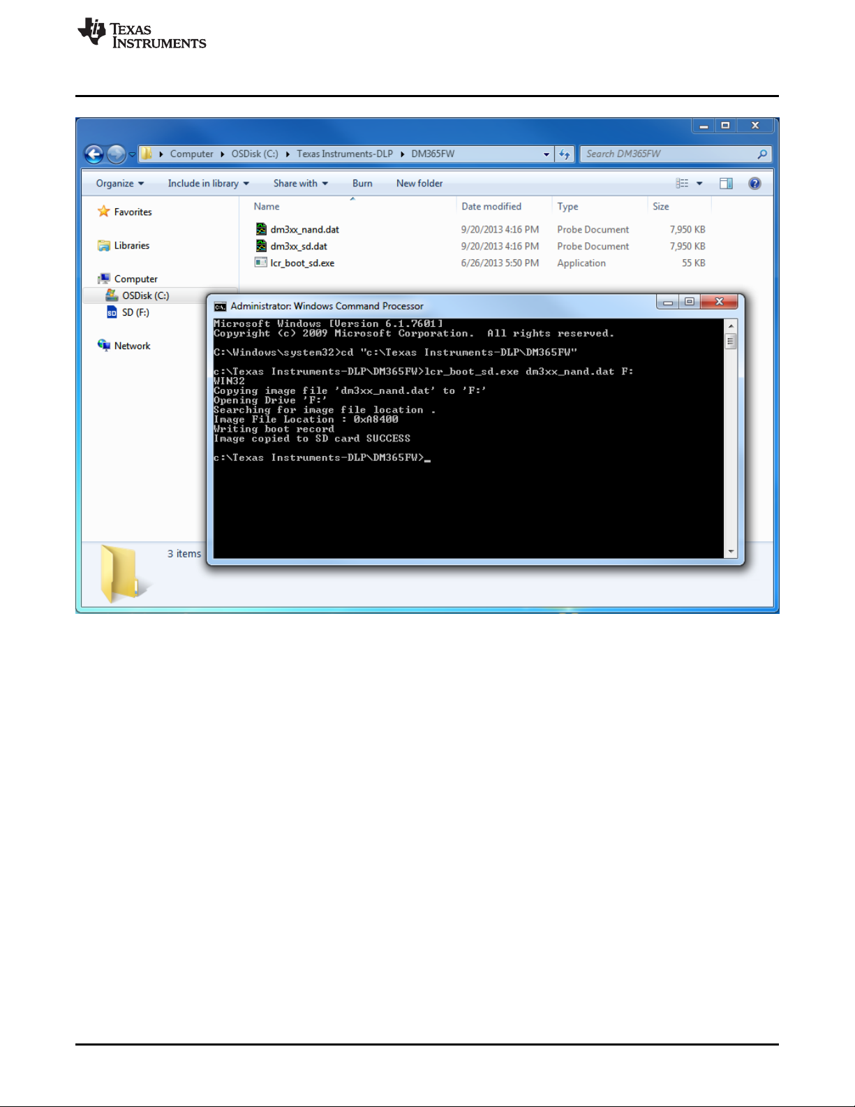
www.ti.com
Upgrading Firmware
Figure 2-61. Windows 7 Create Bootable SD Card Program
2.13.2.2 Setting up the SD Card on Linux
To setup the SD card on Linux or Mac systems, follow these steps:
1. Insert micro-SD card into PC and allow it to mount
• Do not format the SD card. The script formats the card itself.
2. Change to the directory with the DM365 firmware (*.dat) and lcr_boot_sd.sh using the "cd" command.
3. Make the script an executable by running sudo chmod +x lcr_boot_sd.sh
4. Run the script ./lcr_boot_sd.sh -f <sd device> <image file>
• For example, ./lcr_boot_sd.sh -f /dev/sdb dm3xx_sd.dat
• To create a bootable SD card, use the dm3xx_sdv*.dat firmware.
• To create a SD card to flash the DLP LightCrafter NAND, use the dm3xx_nandv*.dat firmware.
• If an “umount: device is busy” or “failed to copy the image to SD card” error occurs, try rerunning
the script.
2.13.2.3 Installing the DM365 Firmware into the NAND
To install the DM365 firmware into the NAND flash, follow these steps :
1. Insert micro-SD card with firmware into an unpowered DLP LightCrafter.
2. Set the DIP switch on system board to the side closest to the micro-SD card connector.
3. Power up the DLP LightCrafter and the LED next to DM365 lights up red.
DLPU006C–January 2012–Revised December 2013 Operating the DLP LightCrafter
Submit Documentation Feedback
Copyright © 2012–2013, Texas Instruments Incorporated
53
Page 54

Changing the Splash Screens
4. Wait until the LED next to DM365 lights up green. This should be a few seconds after the fourth splash
screen.
5. Remove power from the DLP LightCrafter.
6. Remove micro-SD card from DLP LightCrafter and set DIP switch to the side closest to DM365.
7. Power the DLP LightCrafter. A test screen of colored bars should appear after the splash screen if
firmware has been successfully upgraded.
2.13.2.4 Booting from the SD Card
To install the DM365 firmware into the NAND flash, follow these steps:
1. Insert micro-SD card with firmware into an unpowered DLP LightCrafter.
2. Set the DIP switch on system board to the side closest to the micro-SD card connector.
3. Power the DLP LightCrafter. A test screen of colored bars should appear after the splash screens.
2.14 Changing the Splash Screens
The splash images of the DLP LightCrafter's are RGB 427 × 240 pixel images stored in the DLPC300
firmware. To change the splash screens that appear while DLP LightCrafter boots, follow these steps:
1. Select "Upgrade / Splash" and "Splash Utility" tabs
2. Click the "Browse" button to select the DLPC300 firmware file for modifying the splash screens
3. Select the splash screen index
• Selecting the index loads the splash screen into the GUI
4. Click the "Change" button
5. Select the desired 427x240 RGB 24-bit image for that splash screen index
• After selecting, that image is placed in the DLPC300 firmware file selected from step 3
6. Repeat steps 4 through 6 for the other splash screens
7. Load the DLPC300 firmware file, with the new splash screens, from step 3 into the EVM by following
the instructions from Section 2.13.1
www.ti.com
2.15 Loading Images from the SD Card with Slide Show Mode
DLP LightCrafter features a slide show mode which can display large numbers of patterns from the microSD card. To use the slide show mode, follow these steps:
1. Format a new micro-SD card a FAT32 file system
2. Save the required BMP files to the micro-SD card
3. Create "config.txt" file and save to the micro-SD card
• You can specify the delay between images once or multiple times in the text file
• For example, this config.txt file creates a slide show where images 1, 2, and 3 display for 5 s, then
images 4 and 5 display for 10 s
4. Push and hold the button (item 11 from Figure 1-7) to enter slide show mode
5. Before, powering off the DVM push the button again to exit slide show mode
54
Operating the DLP LightCrafter DLPU006C–January 2012–Revised December 2013
Copyright © 2012–2013, Texas Instruments Incorporated
Submit Documentation Feedback
Page 55

DLPU006C–January 2012–Revised December 2013
Developing with the DLP LightCrafter
This chapter describes the tools needed to develop the DLP LightCrafter GUI, MSP430 firmware, and TI's
DVSDK.
3.1 Compiling the GUI Using QT Creator
To compile the DLP LightCrafter GUI, follow these steps:
1. Download QT5.1 from http://qt-project.org/downloads
2. Install QT5.1
3. Open QT Creator
4. Open the "LightCrafterGUI.pro" from the GUI source folder
5. Build the project
3.2 Compiling the MSP430 Firmware Using Code Composer
To compile the MSP430 firmware for DLP LightCrafter, follow these steps:
1. Download Code Composer Studio(CCS) v4.0 from the link,
http://processors.wiki.ti.com/index.php/Download_CCS
2. Open the CCS and Import the project by navigating to, Project--> Import Existing CCS Eclipse Project
3. Browse for the downloaded MSP430v3 source files and click 'Finish'
4. Compile this by building the project in Release/ Debug mode.
5. The build creates a "MSP430.hex" file
6. Copy the MSP430.hex file from the Debug/ Release folder and Paste it in MSP430v3 directory
7. Open the MSDOS command terminal and navigate to this location
8. Execute the MSP430BIN.EXE to merge the Bootstrap loader with this code as follows,
MSP430BIN.EXE -b MSP430_BOOT.hex -m MSP430.hex - o lcrmsp430v25_full.hex Where,
lcrmsp430v3.hex is the output file name
• This command creates two files in the same directory: lcrmsp430v25_full.hex lcrmsp430v25_full.txt
9. Using the GUI, load lcrmsp430v3.txt file in the "Upgrade / Splash" tab.
• The LightCrafter GUI only accepts .txt file for the upgrade.
10. Remove the power and USB cables from the LightCrafter for a complete shutdown
Chapter 3
3.3 Developing with the TI DVSDK
To compile the TI DVSDK for the DLP LightCrafer's DM365, follow these steps:
1. Install the DVSDK Linux build from http://software-
dl.ti.com/dsps/dsps_public_sw/sdo_sb/targetcontent/dvsdk/DVSDK_4_00/4_02_00_06/index_FDS.html
• ./ti-dvsdk_dm365-evm_4_02_00_06 --forcehost
• --forcehost allows installations on systems other than Ubuntu 10.04
2. Install the Code Sourcery toolchain from https://sourcery.mentor.com/sgpp/lite/arm/portal/release858
3. Install the latest DLP LightCrafter DM365 DVSDK from DLP LightCrafter's tool page
http://www.ti.com/tool/dlplightcrafter
4. Follow the instructions from the "DVSDK for LightCrafter.doc" document installed with DLP LightCrafter
DM365 DVSDK.
DLPU006C–January 2012–Revised December 2013 Developing with the DLP LightCrafter
Submit Documentation Feedback
Copyright © 2012–2013, Texas Instruments Incorporated
55
Page 56

This chapter describes the pattern sequences supported by the DLP LightCrafter Module
4.1 Pattern Sequence Background
The DLPC300 device takes as input 16-, 18-, or 24-bit RGB data at up to 60-Hz frame rate. This frame
rate is composed of three colors (red, green, and blue) with each color equally divided in the 60-Hz frame
rate. Thus, each color has a 5.55 ms time slot allocated. Because each color has 5-, 6-, or 8-bit depth,
each color time slot is further divided into bit-planes. A bit-plane is just one-bit representation of all the
pixels in the image. A 24-bit image is decomposed into its bit planes in Figure 4-1.
Chapter 4
DLPU006C–January 2012–Revised December 2013
Pattern Sequences
Figure 4-1. Relationship Between Bit Planes and 24-Bit RGB Images
The length of each bit-plane in the time slot is weighted by the corresponding power of 2 of its binary
representation. This provides a binary pulse-width modulation of the image. For example, a 24-bit RGB
input has three colors with 8-bit depth each. Each color time slot is divided into eight bit-planes, with the
sum of all bit planes in the time slot equal to 256. Figure 4-2 illustrates this partition of bits in a frame.
Figure 4-2. Relationship Between Bit Partition and Time
Therefore, a single video frame is composed of a series of bit planes. Because the DMD mirrors can be
either on or off, an image is created by turning on the mirrors corresponding to the bit set in a bit plane.
With the binary pulse-width modulation, the intensity level of the color is reproduced by controlling the
amount of time the mirror is on. For a 24-bit RGB frame image inputted to the DLPC300, the DLPC300
creates 24 bit planes, stores them on the mDDR, and sends them to the DLP3000 DMD, one bit plane at
a time. Depending on the bit weight of the bit plane, the DLPC300 device controls the time this bit plane is
exposed to light, controlling the intensity of the bit plane. To improve image quality in video frames, the bit
planes, time slots, and color frames are intertwined and interleaved with spatial-temporal algorithms by the
DLPC300 device.
56
Pattern Sequences DLPU006C–January 2012–Revised December 2013
Copyright © 2012–2013, Texas Instruments Incorporated
Submit Documentation Feedback
Page 57

www.ti.com
For other applications where this image enhancement is not desired, the video processing algorithms can
be bypassed and replaced with a specific set of bit planes. The bit depth of the pattern is then allocated
into the corresponding time slots. Furthermore, an output trigger signal is also synchronized with these
time slots to indicate when the image is displayed. For structured light applications, this mechanism
provides the capability to display a set of patterns and signal a camera to capture these patterns overlaid
on an object.
4.2 External Patterns
Using the mechanism described in the previous section, an external device can feed patterns to the
DLPC300 for display. Figure 4-3 illustrates the bit planes and corresponding output triggers for 3-bit, 6-bit,
and 12-bit RGB.
External Patterns
Figure 4-3. Bit Planes and Triggers
While an external device is writing a frame to the DLPC300, the previous frame is displayed. Therefore,
there is a lag of one video frame in relation to the output trigger signal.
Table 4-1 shows the allowed pattern combinations in relation to the bit depth of the external pattern.
Table 4-1. Allowable External Pattern Combinations
COLOR MODE PATTERNS FRAME RATE (Hz) PATTERN RATE
Monochrome
RGB
1-bit per pixel 24 24 * Frame Rate
2-bit per pixel 12 12 * Frame Rate
3-bit per pixel 8 8 * Frame Rate
4-bit per pixel 6 6 * Frame Rate
5-bit per pixel 4 4 * Frame Rate
6-bit per pixel 4 4 * Frame Rate
7-bit per pixel 3 3 * Frame Rate
8-bit per pixel 2 2 * Frame Rate
1-bit per color pixel 8
(3-bit per pixel)
2-bit per color pixel 3
(6-bit per pixel)
4-bit per color pixel 4
(12-bit per pixel)
8-bit per color pixel 1
(24-bit per pixel)
NUMBER OF
PER FRAME
15, 30, 45, or 60
4 * Frame Rate
3 * Frame Rate
2 * Frame Rate
Frame Rate
DLPU006C–January 2012–Revised December 2013 Pattern Sequences
Submit Documentation Feedback
Copyright © 2012–2013, Texas Instruments Incorporated
57
Page 58
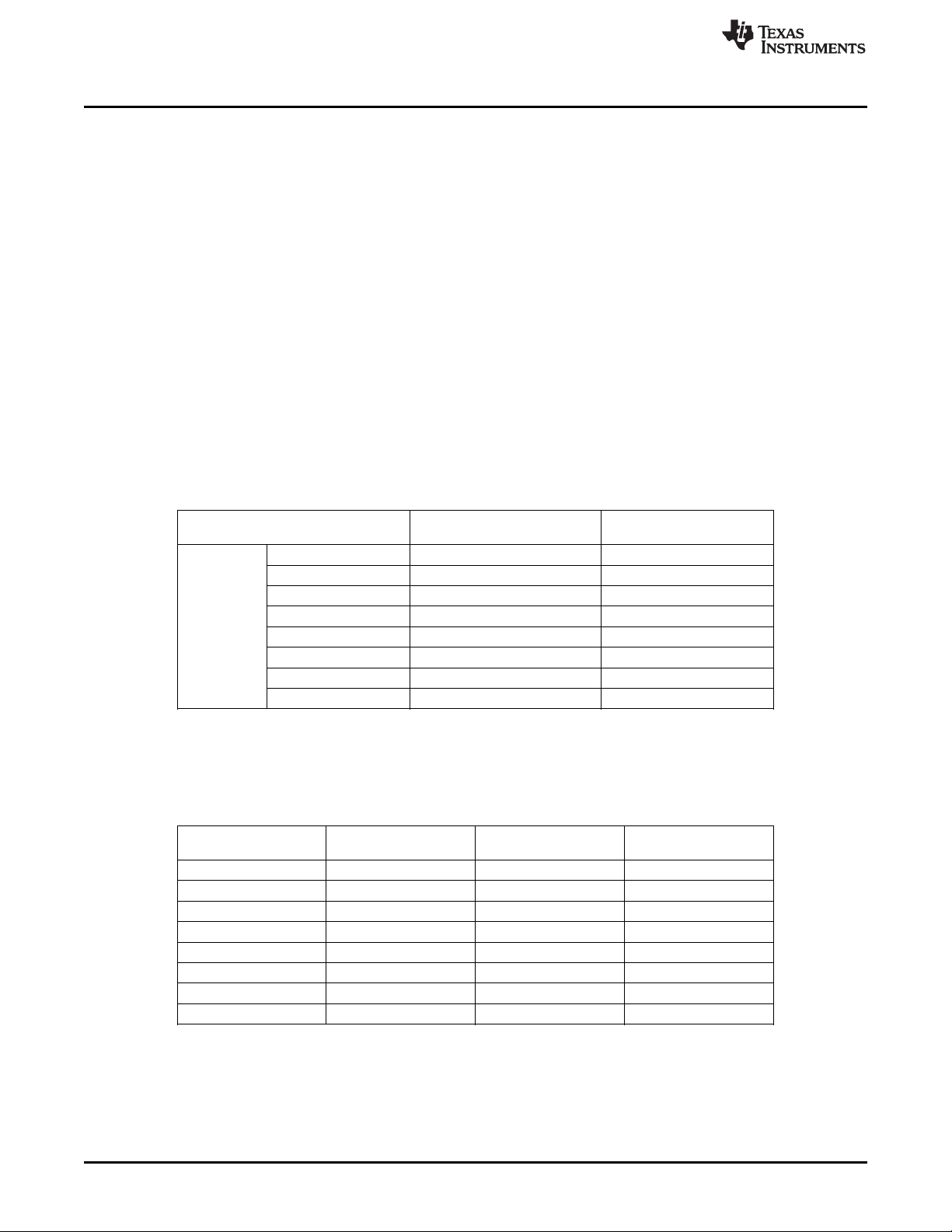
Internal Patterns
4.3 Internal Patterns
In addition to the externally provided sequences through the 24-bit RGB interface of the DLPC300, the
DLP LightCrafter offers the ability to pre-load patterns into the DLPC300’s memory (mDDR) to achieve
faster frame rates. Once the patterns are pre-loaded, the FPGA manages the bit planes stored in the
mDDR. The mDDR accommodates four 608 × 684 images of 24-bit RGB data or 96 bit-planes (24 bitplanes × 4 images). The 96 bit-plane buffer is arranged in a circular buffer style, meaning that the last bit
plane addition to the buffer replaces the oldest stored bit plane.
The oldest set of bit planes in the bit-plane buffer is displayed. Thus, the displayed patterns will lag by
16.66 ms at 60 Hz frame rate while the circular buffer is filled. After the initial 16.66-ms delay, there is no
additional delay for subsequent patterns since the circular buffer is filled.
With the FPGA, the pattern frame rate can be calculated with the following equation:
Pattern Rate = (1/Pattern Exposure Period) + (Bit Plane Load Time) + (Buffer Rotate Overhead)
where
• Typical bit plane load time = 230 µs
• Typical buffer rotate overhead = 135 µs (2)
Table 4-2 shows the maximum pattern rate that can be achieved by using a single FPGA’s internal buffer
in continuous mode.
www.ti.com
Table 4-2. Maximum Internal Pattern Rate
MAXIMUM NUMBER OF MAXIMUM PATTERN RATE
PATTERNS
Monochrome
COLOR MODE
1-bit per pixel 96 4000 Hz
2-bit per pixel 48 1600 Hz
3-bit per pixel 32 480 Hz
4-bit per pixel 24 360 Hz
5-bit per pixel 16 240 Hz
6-bit per pixel 16 240 Hz
7-bit per pixel 12 180 Hz
8-bit per pixel 12 120 Hz
These locally stored patterns have a pre-defined exposure time that is detailed in Table 4-3. Note that the
exposure time decrements by 500 µs from the maximum exposure time. Thus, the minimum might not be
a step size decrease from the second to last minimum exposure time.
Table 4-3. Internal Pattern Exposure Time
BIT DEPTH
8-bit 20,000 8,333 500
7-bit 20,000 4,500 500
6-bit 20,000 2,500 500
5-bit 20,000 2,000 500
4-bit 20,000 1,600 500
3-bit 20,000 1,470 500
2-bit 20,000 666 500
1-bit 100,000 250 500
MAXIMUM EXPOSURE MINIMUM EXPOSURE STEP SIZE DECREASE
TIME (µs) TIME (µs) (µs)
58
Pattern Sequences DLPU006C–January 2012–Revised December 2013
Copyright © 2012–2013, Texas Instruments Incorporated
Submit Documentation Feedback
Page 59
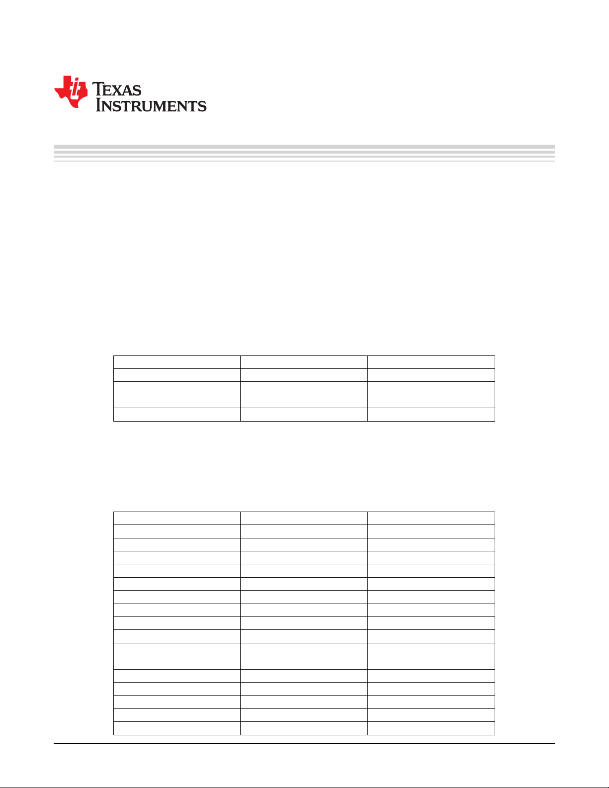
This chapter describes the connector pins of the DLP LightCrafter Module.
5.1 Trigger Connector
The trigger connector pins are listed in Table 5-1. Two matching four pin mating connector part numbers
are:
• Molex part number: 51021-0400
• Digi-Key part number: WM1722-ND
The corresponding crimps part numbers are:
• Molex part number: 50079-8000
• Digi-Key part number: WM1142CT-ND
DESCRIPTION PIN SUPPLY RANGE
Trigger Supply 1 3.3 V
Trigger Input 2 3.3 V
Trigger Output 3 3.3 V
Ground 4 3.3 V
Chapter 5
DLPU006C–January 2012–Revised December 2013
Connectors
Table 5-1. Trigger Connector Pins
5.2 Camera Connector
The camera connector pins are shown in Table 5-2. The supplies are configurable through resistor
population options between 1.8 V, 2.8 V, and 3.3 V.
DESCRIPTION PIN SUPPLY RANGE
Camera Data[2] 1 2.8 V (CAM_IO)
Camera Data[3] 2 2.8 V (CAM_IO)
Camera Data[4] 3 2.8 V (CAM_IO)
Camera Data[5] 4 2.8 V (CAM_IO)
Camera Data[6] 5 2.8 V (CAM_IO)
Camera Data[7] 6 2.8 V (CAM_IO)
Camera Data[8] 7 2.8 V (CAM_IO)
Camera Data[9] 8 2.8 V (CAM_IO)
Camera PCLK 9 2.8 V (CAM_IO)
Digital Supply 10 1.8 V (CAM_DIGITAL)
I/O Supply 11 2.8 V (CAM_IO)
Ground 12 0 V
Analog Supply 13 2.8 V (CAM_ANALOG)
Camera VSYNC 14 2.8 V (CAM_IO)
Camera HSYNC 15 2.8 V (CAM_IO)
CLKIN 24 MHz 16 2.8 V (CAM_IO)
Table 5-2. Camera Connector Pins
DLPU006C–January 2012–Revised December 2013 Connectors
Submit Documentation Feedback
Copyright © 2012–2013, Texas Instruments Incorporated
59
Page 60

UART
5.3 UART
The UART connector pins are shown in Table 5-3.
www.ti.com
Table 5-2. Camera Connector Pins (continued)
DESCRIPTION PIN SUPPLY RANGE
Ground 17 0 V
I2C SDA 18 2.8 V (CAM_IO)
I2C SCL 19 2.8 V (CAM_IO)
Camera Reset 20 2.8 V (CAM_IO)
Camera StandBy 21 2.8 V (CAM_IO)
Camera SubAddr 22 2.8 V (CAM_IO)
Camera Data[0] 23 2.8 V (CAM_IO)
Camera Data[1] 24 2.8 V (CAM_IO)
No Connect 25
Camera Trigger 26 2.8 V (CAM_IO)
Camera DataEn 27 2.8 V (CAM_IO)
No Connect 28
Table 5-3. UART Connector Pins
5.4 I2C
The I2C connector pins are shown in Table 5-4. Two matching four pin mating connector part numbers
are:
• Molex part number: 51021-0400
• Digi-Key part number: WM1722-ND
The corresponding crimps part numbers are:
• Molex part number: 50079-8000
• Digi-Key part number: WM1142CT-ND
DESCRIPTION PIN SUPPLY RANGE
Ground 1 0 V
RX 2 3.3 V
TX 3 3.3 V
Table 5-4. I2C Connector Pins
DESCRIPTION PIN SUPPLY RANGE
I2C SDA 1 3.3 V
I2C SCL 2 3.3 V
Ground 3 0 V
3.3 V Supply 4 3.3 V
5.5 Fan
The fan connector pins are shown in Table 5-5. Two matching connector part numbers are:
The corresponding crimps part numbers are:
60
Connectors DLPU006C–January 2012–Revised December 2013
• Molex part number: 51021-0200
• Digi-Key part number: WM1720-ND
Copyright © 2012–2013, Texas Instruments Incorporated
Submit Documentation Feedback
Page 61

www.ti.com
• Molex part number: 50079-8000
• Digi-Key part number: WM1142CT-ND
5.6 Power
The power connector pins are shown in Table 5-6. Two matching connector part numbers are:
• JST part number: PHR-2(P)
• Digi-Key part number: 455-1165-ND
The corresponding crimps part numbers are:
• JST part number: SPH-002T-P0.5L
• Digi-Key part number: 455-2148-1-ND
Power
Table 5-5. Fan Connector Pins
DESCRIPTION PIN SUPPLY RANGE
Power 1 5 V (SYSPWR)
Switch to Ground 2 0 V
Table 5-6. Power Connector Pins
DESCRIPTION PIN SUPPLY RANGE
Input Supply 1 5 V (SYSPWR)
Ground 2 0 V
DLPU006C–January 2012–Revised December 2013 Connectors
Submit Documentation Feedback
Copyright © 2012–2013, Texas Instruments Incorporated
61
Page 62

Revision A History
www.ti.com
Revision A History
Changes from Original (January 2011) to A Revision .................................................................................................... Page
• Added note about pattern reload when parameters are changed. ............................................................... 37
NOTE: Page numbers for previous revisions may differ from page numbers in the current version.
Revision B History
Changes from A Revision (February 2013) to B Revision ............................................................................................. Page
• Added "Other items needed for operation" section ................................................................................. 15
• Added power connector specifications ............................................................................................... 15
• Changed and clarified UART mini-plug connection description .................................................................. 15
• Changed PC Software section to reflect changes to installation instructions ................................................... 18
• Changed note about reload patterns when parameters are changed ........................................................... 37
NOTE: Page numbers for previous revisions may differ from page numbers in the current version.
Revision C History
Changes from B Revision (July 2013) to C Revision ..................................................................................................... Page
• Deleted LED Current section from "What is in this Module" ........................................................................ 8
• Clarified that DDR2 memory size is 128MB, not 64MB ............................................................................ 12
• Added Software Ovierview section to DLP LightCrafter Module Overview ..................................................... 13
• Changed Embedded Linux Kernel description ...................................................................................... 13
• Added FPGA Operation section to Software Overview ............................................................................ 13
• Added MSP430 Operation section to Software Overview ......................................................................... 14
• Added Operating the DLP LightCrafter section ..................................................................................... 18
• Added Changing the DLP LightCrafter's IP Address section ..................................................................... 27
• Added Selecting the Display Mode section .......................................................................................... 29
• Added Setting the LED Current section .............................................................................................. 30
• Added Controlling Image Orientation and Rotation section ....................................................................... 31
• Added Triggering External Peripherals section ..................................................................................... 32
• Added Streaming 24-bit RGB Video from the HDMI Port section ................................................................ 34
• Added Creating Pattern Sequences section ........................................................................................ 35
• Added Uploading Static Images or Colors section ................................................................................. 45
• Added Using Test Patterns section ................................................................................................... 46
• Added Saving and Loading Solutions section ....................................................................................... 46
• Added Capturing Images using to Camera Connector section ................................................................... 47
• Added Changing the Splash Screens section ....................................................................................... 54
• Added Loading Images from the SD Card section ................................................................................. 54
NOTE: Page numbers for previous revisions may differ from page numbers in the current version.
62
Revision History DLPU006C–January 2012–Revised December 2013
Copyright © 2012–2013, Texas Instruments Incorporated
Submit Documentation Feedback
Page 63

EVALUATION BOARD/KIT/MODULE (EVM) ADDITIONAL TERMS
Texas Instruments (TI) provides the enclosed Evaluation Board/Kit/Module (EVM) under the following conditions:
The user assumes all responsibility and liability for proper and safe handling of the goods. Further, the user indemnifies TI from all claims
arising from the handling or use of the goods.
Should this evaluation board/kit not meet the specifications indicated in the User’s Guide, the board/kit may be returned within 30 days from
the date of delivery for a full refund. THE FOREGOING LIMITED WARRANTY IS THE EXCLUSIVE WARRANTY MADE BY SELLER TO
BUYER AND IS IN LIEU OF ALL OTHER WARRANTIES, EXPRESSED, IMPLIED, OR STATUTORY, INCLUDING ANY WARRANTY OF
MERCHANTABILITY OR FITNESS FOR ANY PARTICULAR PURPOSE. EXCEPT TO THE EXTENT OF THE INDEMNITY SET FORTH
ABOVE, NEITHER PARTY SHALL BE LIABLE TO THE OTHER FOR ANY INDIRECT, SPECIAL, INCIDENTAL, OR CONSEQUENTIAL
DAMAGES.
Please read the User's Guide and, specifically, the Warnings and Restrictions notice in the User's Guide prior to handling the product. This
notice contains important safety information about temperatures and voltages. For additional information on TI's environmental and/or safety
programs, please visit www.ti.com/esh or contact TI.
No license is granted under any patent right or other intellectual property right of TI covering or relating to any machine, process, or
combination in which such TI products or services might be or are used. TI currently deals with a variety of customers for products, and
therefore our arrangement with the user is not exclusive. TI assumes no liability for applications assistance, customer product design,
software performance, or infringement of patents or services described herein.
REGULATORY COMPLIANCE INFORMATION
As noted in the EVM User’s Guide and/or EVM itself, this EVM and/or accompanying hardware may or may not be subject to the Federal
Communications Commission (FCC) and Industry Canada (IC) rules.
For EVMs not subject to the above rules, this evaluation board/kit/module is intended for use for ENGINEERING DEVELOPMENT,
DEMONSTRATION OR EVALUATION PURPOSES ONLY and is not considered by TI to be a finished end product fit for general consumer
use. It generates, uses, and can radiate radio frequency energy and has not been tested for compliance with the limits of computing
devices pursuant to part 15 of FCC or ICES-003 rules, which are designed to provide reasonable protection against radio frequency
interference. Operation of the equipment may cause interference with radio communications, in which case the user at his own expense will
be required to take whatever measures may be required to correct this interference.
General Statement for EVMs including a radio
User Power/Frequency Use Obligations: This radio is intended for development/professional use only in legally allocated frequency and
power limits. Any use of radio frequencies and/or power availability of this EVM and its development application(s) must comply with local
laws governing radio spectrum allocation and power limits for this evaluation module. It is the user’s sole responsibility to only operate this
radio in legally acceptable frequency space and within legally mandated power limitations. Any exceptions to this are strictly prohibited and
unauthorized by Texas Instruments unless user has obtained appropriate experimental/development licenses from local regulatory
authorities, which is responsibility of user including its acceptable authorization.
For EVMs annotated as FCC – FEDERAL COMMUNICATIONS COMMISSION Part 15 Compliant
Caution
This device complies with part 15 of the FCC Rules. Operation is subject to the following two conditions: (1) This device may not cause
harmful interference, and (2) this device must accept any interference received, including interference that may cause undesired operation.
Changes or modifications not expressly approved by the party responsible for compliance could void the user's authority to operate the
equipment.
FCC Interference Statement for Class A EVM devices
This equipment has been tested and found to comply with the limits for a Class A digital device, pursuant to part 15 of the FCC Rules.
These limits are designed to provide reasonable protection against harmful interference when the equipment is operated in a commercial
environment. This equipment generates, uses, and can radiate radio frequency energy and, if not installed and used in accordance with the
instruction manual, may cause harmful interference to radio communications. Operation of this equipment in a residential area is likely to
cause harmful interference in which case the user will be required to correct the interference at his own expense.
Page 64

FCC Interference Statement for Class B EVM devices
This equipment has been tested and found to comply with the limits for a Class B digital device, pursuant to part 15 of the FCC Rules.
These limits are designed to provide reasonable protection against harmful interference in a residential installation. This equipment
generates, uses and can radiate radio frequency energy and, if not installed and used in accordance with the instructions, may cause
harmful interference to radio communications. However, there is no guarantee that interference will not occur in a particular installation. If
this equipment does cause harmful interference to radio or television reception, which can be determined by turning the equipment off and
on, the user is encouraged to try to correct the interference by one or more of the following measures:
• Reorient or relocate the receiving antenna.
• Increase the separation between the equipment and receiver.
• Connect the equipment into an outlet on a circuit different from that to which the receiver is connected.
• Consult the dealer or an experienced radio/TV technician for help.
For EVMs annotated as IC – INDUSTRY CANADA Compliant
This Class A or B digital apparatus complies with Canadian ICES-003.
Changes or modifications not expressly approved by the party responsible for compliance could void the user’s authority to operate the
equipment.
Concerning EVMs including radio transmitters
This device complies with Industry Canada licence-exempt RSS standard(s). Operation is subject to the following two conditions: (1) this
device may not cause interference, and (2) this device must accept any interference, including interference that may cause undesired
operation of the device.
Concerning EVMs including detachable antennas
Under Industry Canada regulations, this radio transmitter may only operate using an antenna of a type and maximum (or lesser) gain
approved for the transmitter by Industry Canada. To reduce potential radio interference to other users, the antenna type and its gain should
be so chosen that the equivalent isotropically radiated power (e.i.r.p.) is not more than that necessary for successful communication.
This radio transmitter has been approved by Industry Canada to operate with the antenna types listed in the user guide with the maximum
permissible gain and required antenna impedance for each antenna type indicated. Antenna types not included in this list, having a gain
greater than the maximum gain indicated for that type, are strictly prohibited for use with this device.
Cet appareil numérique de la classe A ou B est conforme à la norme NMB-003 du Canada.
Les changements ou les modifications pas expressément approuvés par la partie responsable de la conformité ont pu vider l’autorité de
l'utilisateur pour actionner l'équipement.
Concernant les EVMs avec appareils radio
Le présent appareil est conforme aux CNR d'Industrie Canada applicables aux appareils radio exempts de licence. L'exploitation est
autorisée aux deux conditions suivantes : (1) l'appareil ne doit pas produire de brouillage, et (2) l'utilisateur de l'appareil doit accepter tout
brouillage radioélectrique subi, même si le brouillage est susceptible d'en compromettre le fonctionnement.
Concernant les EVMs avec antennes détachables
Conformément à la réglementation d'Industrie Canada, le présent émetteur radio peut fonctionner avec une antenne d'un type et d'un gain
maximal (ou inférieur) approuvé pour l'émetteur par Industrie Canada. Dans le but de réduire les risques de brouillage radioélectrique à
l'intention des autres utilisateurs, il faut choisir le type d'antenne et son gain de sorte que la puissance isotrope rayonnée équivalente
(p.i.r.e.) ne dépasse pas l'intensité nécessaire à l'établissement d'une communication satisfaisante.
Le présent émetteur radio a été approuvé par Industrie Canada pour fonctionner avec les types d'antenne énumérés dans le manuel
d’usage et ayant un gain admissible maximal et l'impédance requise pour chaque type d'antenne. Les types d'antenne non inclus dans
cette liste, ou dont le gain est supérieur au gain maximal indiqué, sont strictement interdits pour l'exploitation de l'émetteur.
SPACER
SPACER
SPACER
SPACER
SPACER
SPACER
SPACER
SPACER
Page 65

【【Important Notice for Users of EVMs for RF Products in Japan】】
This development kit is NOT certified as Confirming to Technical Regulations of Radio Law of Japan
If you use this product in Japan, you are required by Radio Law of Japan to follow the instructions below with respect to this product:
1. Use this product in a shielded room or any other test facility as defined in the notification #173 issued by Ministry of Internal Affairs and
Communications on March 28, 2006, based on Sub-section 1.1 of Article 6 of the Ministry’s Rule for Enforcement of Radio Law of
Japan,
2. Use this product only after you obtained the license of Test Radio Station as provided in Radio Law of Japan with respect to this
product, or
3. Use of this product only after you obtained the Technical Regulations Conformity Certification as provided in Radio Law of Japan with
respect to this product. Also, please do not transfer this product, unless you give the same notice above to the transferee. Please note
that if you could not follow the instructions above, you will be subject to penalties of Radio Law of Japan.
(address) 24-1, Nishi-Shinjuku 6 chome, Shinjuku-ku, Tokyo, Japan
http://www.tij.co.jp
【無線電波を送信する製品の開発キットをお使いになる際の注意事項】
本開発キットは技術基準適合証明を受けておりません。
本製品のご使用に際しては、電波法遵守のため、以下のいずれかの措置を取っていただく必要がありますのでご注意ください。
1. 電波法施行規則第6条第1項第1号に基づく平成18年3月28日総務省告示第173号で定められた電波暗室等の試験設備でご使用いただく。
2. 実験局の免許を取得後ご使用いただく。
3. 技術基準適合証明を取得後ご使用いただく。
なお、本製品は、上記の「ご使用にあたっての注意」を譲渡先、移転先に通知しない限り、譲渡、移転できないものとします。
上記を遵守頂けない場合は、電波法の罰則が適用される可能性があることをご留意ください。
日本テキサス・インスツルメンツ株式会社
東京都新宿区西新宿6丁目24番1号
西新宿三井ビル
http://www.tij.co.jp
Texas Instruments Japan Limited
SPACER
SPACER
SPACER
SPACER
SPACER
SPACER
SPACER
SPACER
SPACER
SPACER
SPACER
SPACER
SPACER
SPACER
SPACER
SPACER
SPACER
Page 66

EVALUATION BOARD/KIT/MODULE (EVM)
WARNINGS, RESTRICTIONS AND DISCLAIMERS
For Feasibility Evaluation Only, in Laboratory/Development Environments. Unless otherwise indicated, this EVM is not a finished
electrical equipment and not intended for consumer use. It is intended solely for use for preliminary feasibility evaluation in
laboratory/development environments by technically qualified electronics experts who are familiar with the dangers and application risks
associated with handling electrical mechanical components, systems and subsystems. It should not be used as all or part of a finished end
product.
Your Sole Responsibility and Risk. You acknowledge, represent and agree that:
1. You have unique knowledge concerning Federal, State and local regulatory requirements (including but not limited to Food and Drug
Administration regulations, if applicable) which relate to your products and which relate to your use (and/or that of your employees,
affiliates, contractors or designees) of the EVM for evaluation, testing and other purposes.
2. You have full and exclusive responsibility to assure the safety and compliance of your products with all such laws and other applicable
regulatory requirements, and also to assure the safety of any activities to be conducted by you and/or your employees, affiliates,
contractors or designees, using the EVM. Further, you are responsible to assure that any interfaces (electronic and/or mechanical)
between the EVM and any human body are designed with suitable isolation and means to safely limit accessible leakage currents to
minimize the risk of electrical shock hazard.
3. Since the EVM is not a completed product, it may not meet all applicable regulatory and safety compliance standards (such as UL,
CSA, VDE, CE, RoHS and WEEE) which may normally be associated with similar items. You assume full responsibility to determine
and/or assure compliance with any such standards and related certifications as may be applicable. You will employ reasonable
safeguards to ensure that your use of the EVM will not result in any property damage, injury or death, even if the EVM should fail to
perform as described or expected.
4. You will take care of proper disposal and recycling of the EVM’s electronic components and packing materials.
Certain Instructions. It is important to operate this EVM within TI’s recommended specifications and environmental considerations per the
user guidelines. Exceeding the specified EVM ratings (including but not limited to input and output voltage, current, power, and
environmental ranges) may cause property damage, personal injury or death. If there are questions concerning these ratings please contact
a TI field representative prior to connecting interface electronics including input power and intended loads. Any loads applied outside of the
specified output range may result in unintended and/or inaccurate operation and/or possible permanent damage to the EVM and/or
interface electronics. Please consult the EVM User's Guide prior to connecting any load to the EVM output. If there is uncertainty as to the
load specification, please contact a TI field representative. During normal operation, some circuit components may have case temperatures
greater than 60°C as long as the input and output are maintained at a normal ambient operating temperature. These components include
but are not limited to linear regulators, switching transistors, pass transistors, and current sense resistors which can be identified using the
EVM schematic located in the EVM User's Guide. When placing measurement probes near these devices during normal operation, please
be aware that these devices may be very warm to the touch. As with all electronic evaluation tools, only qualified personnel knowledgeable
in electronic measurement and diagnostics normally found in development environments should use these EVMs.
Agreement to Defend, Indemnify and Hold Harmless. You agree to defend, indemnify and hold TI, its licensors and their representatives
harmless from and against any and all claims, damages, losses, expenses, costs and liabilities (collectively, "Claims") arising out of or in
connection with any use of the EVM that is not in accordance with the terms of the agreement. This obligation shall apply whether Claims
arise under law of tort or contract or any other legal theory, and even if the EVM fails to perform as described or expected.
Safety-Critical or Life-Critical Applications. If you intend to evaluate the components for possible use in safety critical applications (such
as life support) where a failure of the TI product would reasonably be expected to cause severe personal injury or death, such as devices
which are classified as FDA Class III or similar classification, then you must specifically notify TI of such intent and enter into a separate
Assurance and Indemnity Agreement.
Mailing Address: Texas Instruments, Post Office Box 655303, Dallas, Texas 75265
Copyright © 2013, Texas Instruments Incorporated
Page 67

IMPORTANT NOTICE
Texas Instruments Incorporated and its subsidiaries (TI) reserve the right to make corrections, enhancements, improvements and other
changes to its semiconductor products and services per JESD46, latest issue, and to discontinue any product or service per JESD48, latest
issue. Buyers should obtain the latest relevant information before placing orders and should verify that such information is current and
complete. All semiconductor products (also referred to herein as “components”) are sold subject to TI’s terms and conditions of sale
supplied at the time of order acknowledgment.
TI warrants performance of its components to the specifications applicable at the time of sale, in accordance with the warranty in TI’s terms
and conditions of sale of semiconductor products. Testing and other quality control techniques are used to the extent TI deems necessary
to support this warranty. Except where mandated by applicable law, testing of all parameters of each component is not necessarily
performed.
TI assumes no liability for applications assistance or the design of Buyers’ products. Buyers are responsible for their products and
applications using TI components. To minimize the risks associated with Buyers’ products and applications, Buyers should provide
adequate design and operating safeguards.
TI does not warrant or represent that any license, either express or implied, is granted under any patent right, copyright, mask work right, or
other intellectual property right relating to any combination, machine, or process in which TI components or services are used. Information
published by TI regarding third-party products or services does not constitute a license to use such products or services or a warranty or
endorsement thereof. Use of such information may require a license from a third party under the patents or other intellectual property of the
third party, or a license from TI under the patents or other intellectual property of TI.
Reproduction of significant portions of TI information in TI data books or data sheets is permissible only if reproduction is without alteration
and is accompanied by all associated warranties, conditions, limitations, and notices. TI is not responsible or liable for such altered
documentation. Information of third parties may be subject to additional restrictions.
Resale of TI components or services with statements different from or beyond the parameters stated by TI for that component or service
voids all express and any implied warranties for the associated TI component or service and is an unfair and deceptive business practice.
TI is not responsible or liable for any such statements.
Buyer acknowledges and agrees that it is solely responsible for compliance with all legal, regulatory and safety-related requirements
concerning its products, and any use of TI components in its applications, notwithstanding any applications-related information or support
that may be provided by TI. Buyer represents and agrees that it has all the necessary expertise to create and implement safeguards which
anticipate dangerous consequences of failures, monitor failures and their consequences, lessen the likelihood of failures that might cause
harm and take appropriate remedial actions. Buyer will fully indemnify TI and its representatives against any damages arising out of the use
of any TI components in safety-critical applications.
In some cases, TI components may be promoted specifically to facilitate safety-related applications. With such components, TI’s goal is to
help enable customers to design and create their own end-product solutions that meet applicable functional safety standards and
requirements. Nonetheless, such components are subject to these terms.
No TI components are authorized for use in FDA Class III (or similar life-critical medical equipment) unless authorized officers of the parties
have executed a special agreement specifically governing such use.
Only those TI components which TI has specifically designated as military grade or “enhanced plastic” are designed and intended for use in
military/aerospace applications or environments. Buyer acknowledges and agrees that any military or aerospace use of TI components
which have not been so designated is solely at the Buyer's risk, and that Buyer is solely responsible for compliance with all legal and
regulatory requirements in connection with such use.
TI has specifically designated certain components as meeting ISO/TS16949 requirements, mainly for automotive use. In any case of use of
non-designated products, TI will not be responsible for any failure to meet ISO/TS16949.
Products Applications
Audio www.ti.com/audio Automotive and Transportation www.ti.com/automotive
Amplifiers amplifier.ti.com Communications and Telecom www.ti.com/communications
Data Converters dataconverter.ti.com Computers and Peripherals www.ti.com/computers
DLP® Products www.dlp.com Consumer Electronics www.ti.com/consumer-apps
DSP dsp.ti.com Energy and Lighting www.ti.com/energy
Clocks and Timers www.ti.com/clocks Industrial www.ti.com/industrial
Interface interface.ti.com Medical www.ti.com/medical
Logic logic.ti.com Security www.ti.com/security
Power Mgmt power.ti.com Space, Avionics and Defense www.ti.com/space-avionics-defense
Microcontrollers microcontroller.ti.com Video and Imaging www.ti.com/video
RFID www.ti-rfid.com
OMAP Applications Processors www.ti.com/omap TI E2E Community e2e.ti.com
Wireless Connectivity www.ti.com/wirelessconnectivity
Mailing Address: Texas Instruments, Post Office Box 655303, Dallas, Texas 75265
Copyright © 2013, Texas Instruments Incorporated
Page 68

Mouser Electronics
Authorized Distributor
Click to View Pricing, Inventory, Delivery & Lifecycle Information:
Texas Instruments:
DLPLIGHTCRAFTER
 Loading...