

Page 1

bq35100
Technical Reference Manual
Literature Number: SLUUBH1C
August 2016–Revised March 2018
Page 2

Contents
Preface ........................................................................................................................................ 5
1 Introduction......................................................................................................................... 7
2 Basic Measurement Systems................................................................................................. 8
2.1 Voltage ........................................................................................................................ 8
2.2 Temperature.................................................................................................................. 8
2.3 Coulombs ..................................................................................................................... 8
2.4 Current ........................................................................................................................ 8
3 Factory Calibration ............................................................................................................. 10
3.1 General I
3.2 Calibration Overview....................................................................................................... 10
3.2.1 Method.............................................................................................................. 10
3.2.2 Sequence........................................................................................................... 10
3.3 Enter CALIBRATION Mode ............................................................................................... 11
3.4 Voltage Calibration......................................................................................................... 12
3.5 CC Offset.................................................................................................................... 13
3.6 Board Offset................................................................................................................. 14
3.7 Obtain Raw Calibration Data ............................................................................................. 15
3.8 Current Calibration ......................................................................................................... 16
3.9 Temperature Calibration................................................................................................... 17
3.10 Floating Point Conversion................................................................................................. 18
3.11 Exit CALIBRATION Mode................................................................................................. 19
4 Basic Configuration............................................................................................................ 20
4.1 Operation Config A......................................................................................................... 20
5 Battery Gauging ................................................................................................................. 21
5.1 ACCUMULATOR Mode ................................................................................................... 21
5.1.1 Total Capacity Update ............................................................................................ 21
5.2 STATE-OF-HEALTH (SOH) Mode....................................................................................... 21
5.2.1 Low State-Of-Health Alert........................................................................................ 21
5.3 End-Of-Service (EOS) Mode ............................................................................................. 22
5.3.1 Initial EOS Learning............................................................................................... 22
5.3.2 End-Of-Service Detection ........................................................................................ 23
5.3.3 End-Of-Service Smoothing....................................................................................... 23
6 Power Control.................................................................................................................... 25
6.1 Device Functional Modes ................................................................................................. 25
6.2 Flash Updates .............................................................................................................. 27
7 Battery Condition Warnings................................................................................................. 28
7.1 Battery Low Warning....................................................................................................... 28
7.2 Temperature Low Warning................................................................................................ 28
7.3 Temperature High Warning ............................................................................................... 28
7.4 Battery Low SOC Warning................................................................................................ 29
7.5 Battery EOS OCV BAD Warning......................................................................................... 29
8 ALERT Signal..................................................................................................................... 30
9 Lifetime Data Collection ...................................................................................................... 31
2
C Command Information ...................................................................................... 10
2
Contents
SLUUBH1C–August 2016–Revised March 2018
Copyright © 2016–2018, Texas Instruments Incorporated
Submit Documentation Feedback
Page 3

www.ti.com
10 SHA-1 Authentication.......................................................................................................... 32
10.1 Overview..................................................................................................................... 32
10.2 HMAC Description.......................................................................................................... 32
10.3 Authentication............................................................................................................... 32
10.4 AuthenticateData(): 0x40…0x53 ......................................................................................... 33
10.5 AuthenticateChecksum(): 0x54........................................................................................... 33
11 Data Commands................................................................................................................. 34
11.1 Command Summary....................................................................................................... 34
11.2 Control(): 0x00/0x01 ....................................................................................................... 34
11.3 CONTROL_STATUS: 0x0000 ............................................................................................ 35
11.3.1 DEVICE_TYPE: 0x0001......................................................................................... 37
11.3.2 FW_VERSION: 0x0002 ......................................................................................... 37
11.3.3 HW_VERSION: 0x0003 ......................................................................................... 37
11.3.4 STATIC_CHEM_DF_CHKSUM: 0x0005...................................................................... 37
11.3.5 CHEM_ID: 0x0006 ............................................................................................... 37
11.3.6 PREV_MACWRITE: 0x0007.................................................................................... 37
11.3.7 BOARD_OFFSET: 0x0009...................................................................................... 37
11.3.8 CC_OFFSET: 0x000A........................................................................................... 37
11.3.9 CC_OFFSET_SAVE: 0x000B .................................................................................. 37
11.3.10 GAUGE_START: 0x0011...................................................................................... 37
11.3.11 GAUGE_STOP: 0x0012 ....................................................................................... 38
11.3.12 SEALED: 0x0020 ............................................................................................... 38
11.3.13 CAL_ENABLE: 0x002D........................................................................................ 38
11.3.14 LT_ENABLE: 0x002E .......................................................................................... 38
11.3.15 RESET: 0x0041................................................................................................. 38
11.3.16 NEW_BATTERY: 0xA613 ..................................................................................... 38
11.4 AccumulatedCapacity(): 0x02/0x05...................................................................................... 38
11.5 Temperature(): 0x06/0x07................................................................................................. 38
11.6 Voltage(): 0x08/0x09....................................................................................................... 38
11.7 BatteryStatus() 0x0A....................................................................................................... 38
11.8 BatteryAlert() 0x0B......................................................................................................... 39
11.9 Current(): 0x0C/0x0D ...................................................................................................... 39
11.10 ScaledR(): 0x16/0x17 ..................................................................................................... 39
11.11 MeasuredZ(): 0x22/0x23.................................................................................................. 39
11.12 InternalTemperature(): 0x28/0x29 ....................................................................................... 39
11.13 StateOfHealth(): 0x2E/0x2F .............................................................................................. 40
11.14 DesignCapacity(): 0x3C/3D............................................................................................... 40
11.15 ManufacturerAccessControl(): 0x3E/0x3F ............................................................................. 40
11.16 MACData(): 0x40 through 0x5F.......................................................................................... 40
11.17 MACDataSum(): 0x60..................................................................................................... 40
11.18 MACDataLen(): 0x61 ..................................................................................................... 40
12 Data Flash ......................................................................................................................... 41
12.1 Accessing Data Flash...................................................................................................... 41
12.1.1 Write to DF Example............................................................................................. 41
12.1.2 Read from DF Example ......................................................................................... 41
12.1.3 Auto-Increment Reading ........................................................................................ 41
12.2 Access Modes .............................................................................................................. 41
12.2.1 Sealing/Unsealing Data Flash Access......................................................................... 42
12.3 BlockDataChecksum(): 0x60.............................................................................................. 42
12.4 BlockDataLength(): 0x61 .................................................................................................. 42
12.5 BlockDataControl(): 0x62.................................................................................................. 42
13 Data Flash Summary........................................................................................................... 43
SLUUBH1C–August 2016–Revised March 2018
Submit Documentation Feedback
Copyright © 2016–2018, Texas Instruments Incorporated
Contents
3
Page 4

www.ti.com
14 Communications ................................................................................................................ 48
14.1 I
2
C Interface................................................................................................................. 48
Revision History.......................................................................................................................... 49
4
Contents
SLUUBH1C–August 2016–Revised March 2018
Copyright © 2016–2018, Texas Instruments Incorporated
Submit Documentation Feedback
Page 5

About This Manual
This technical reference manual (TRM) discusses the modules and peripherals of the bq35100 device,
and how each is used to build a complete battery fuel gauge and end-of-service monitor. Content in this
TRM complements, not supersedes, information in the bq35100 Lithium Primary Battery Fuel Gauge and
End-Of-Service Monitor Data Sheet (SLUSCM6).
Notational Conventions
This document uses the following conventions:
• Hexadecimal numbers may be shown with the suffix h or the prefix 0x. For example, the following
number is 40 hexadecimal (decimal 64): 40h or 0x40.
• Registers in this document are shown in figures and described in tables.
– Each register figure shows a rectangle divided into fields that represent the fields of the register.
Each field is labeled with its bit name, its beginning and ending bit numbers above, and its
read/write properties with default reset value below. A legend explains the notation used for the
properties.
– Reserved bits in a register figure can have one of multiple meanings:
• Not implemented on the device,
• Reserved for future device expansion,
• Reserved for TI testing,
• Reserved configurations of the device that are not supported.
– Writing non-default values to the Reserved bits could cause unexpected behavior and should be
avoided.
Preface
SLUUBH1C–August 2016–Revised March 2018
Read This First
Formatting in This Document
The following formatting convention is used in this document:
• SBS Commands: italic with parenthesis and no breaking spaces; for example, RemainingCapacity()
• Data Flash: italic, bold, and breaking spaces; for example, Design Capacity
• Data Flash Bits: italic and bold; for example, [LED1]
• Register Bits and Flags: italic and brackets; for example, [TDA]
• Modes and States: ALL CAPITALS; for example, UNSEALED
Trademarks
E2E is a trademark of Texas Instruments.
All other trademarks are the property of their respective owners.
Related Documentation From Texas Instruments
See the bq35100 Lithium Primary Battery Fuel Gauge and End-Of-Service Monitor Data Sheet
(SLUSCM6).
For product information, visit the Texas Instruments website at http://www.ti.com/product/bq35100.
SLUUBH1C–August 2016–Revised March 2018
Submit Documentation Feedback
Copyright © 2016–2018, Texas Instruments Incorporated
Read This First
5
Page 6

Community Resources
Community Resources
The following links connect to TI community resources. Linked contents are provided "AS IS" by the
respective contributors. They do not constitute TI specifications and do not necessarily reflect TI's views;
see TI's Terms of Use.
TI E2E™ Online Community— TI's Engineer-to-Engineer (E2E) Community. Created to foster
collaboration among engineers. At e2e.ti.com, you can ask questions, share knowledge, explore
ideas and help solve problems with fellow engineers.
Design Support— TI's Design Support Quickly find helpful E2E forums along with design support tools
and contact information for technical support.
Definitions
A Battery Glossary is available at the Battery University on ti.com.
Glossary
TI Glossary —This glossary lists and explains terms, acronyms, and definitions.
www.ti.com
6
Read This First
SLUUBH1C–August 2016–Revised March 2018
Copyright © 2016–2018, Texas Instruments Incorporated
Submit Documentation Feedback
Page 7

Chapter 1
SLUUBH1C–August 2016–Revised March 2018
Introduction
The bq35100 Battery Fuel Gauge and End-Of-Service Monitor provides highly configurable fuel gauging
for non-rechargeable lithium primary batteries—without requiring forced discharge of the battery. Built so
that optimization is not necessary, the patented TI gauging algorithms support replaceable batteries and
enable accurate results with ultra-low average power consumption through host control via the GAUGE
ENABLE (GE) pin.
The fuel gauging functions use voltage, current, and temperature information to provide State-Of-Health
(SOH) and End-Of-Service (EOS) data. The bq35100 device is only required to be powered long enough
to gather data and to make calculations to support the selected algorithm and the frequency of updates
required by the system.
The host can read the gathered data through a 400-kHz I2C bus. An ALERT output is also available to
interrupt the host, based on a variety of configurable options.
The device has extended capabilities, including:
• Fuel Gauge for Single- and Multi-Cell Primary (Non-Rechargeable) Batteries
• Supports Lithium Thionyl Chloride (LiSOCl2) and Lithium Manganese Dioxide (LiMnO2)
• Provides Four Configurable Algorithm Options:
– Coulomb Accumulation (ACC)
– State-Of-Health (SOH)
– End-Of-Service (EOS)
• Ultra-Low Average Power Consumption Supported Through Gauge-Enable Control
• Accurate Coulomb Counter, Voltage, and Temperature Measurement Options
• I2C Host Communication, Providing Battery Parameter and Status Access
• Configurable Host Interrupt
• Data Logging Options
• SHA-1 Authentication
SLUUBH1C–August 2016–Revised March 2018
Submit Documentation Feedback
Copyright © 2016–2018, Texas Instruments Incorporated
Introduction
7
Page 8

2.1 Voltage
The bq35100 device measures the BAT input using the integrated delta-sigma ADC, which is scaled by
the internal translation network, through the ADC. The measured voltage is available through Voltage(),
and is updated for the host to read once per second. The translation gain function is determined by a
calibration process. See Factory Calibration for further details.
In systems where the battery voltage is greater than V
external voltage scaling circuit is required. If [EXTVCELL] is set, then the voltage is measured via the VIN
pin. The input to VIN must be scaled to a maximum of 1 V.
The VEN pin can be used to enable and disable the external divider to conserve power. The firmware will
then scale this < 1-V value to reflect an average cell value, and then again by the number of series cells to
reflect the full battery voltage value.
Chapter 2
SLUUBH1C–August 2016–Revised March 2018
Basic Measurement Systems
MAX (for example, 2-series cell or more), an
IN(BAT)
CLASS SUBCLASS NAME TYPE SIZE MIN VALUE
Gas gauging Design
The configured battery voltage measurement is made available through the Voltage() command.
2.2 Temperature
The device can measure temperature through an integrated temperature sensor or an external NTC
thermistor using the integrated delta-sigma ADC. Only one source can be used for gauging and the
selection is made by setting Operation A [TEMPS] appropriately. The resulting measured temperature is
available through the Temperature() command, and is updated for the host to read once per second. The
internal temperature sensor is always measured in support of voltage measurement accuracy, and the
result is also available through the InternalTemperature() command.
When an external thermistor is used, REG25 (pin 7) is used to bias the thermistor, and TS (pin 11) is used
to measure the thermistor voltage (a pull-down circuit is implemented inside the device). The device then
correlates the voltage to temperature, assuming the thermistor is a Semitec 103AT or similar device.
There is a configurable option for the host to write the temperature to the Temperature() command when
[WRTEMP] = 1. This option is disabled by default.
2.3 Coulombs
The integrating delta-sigma ADC (coulomb counter) in the device measures the discharge flow of the
battery by measuring the voltage drop across a small-value sense resistor between the SRP and SRN
pins in a range from –0.125 V to 0.125 V. The device continuously monitors the measured current and
integrates this value over time using an internal counter. This measurement is updated for the host to read
once per second.
Series cell
count
MAX
VALUE
Integer 1 1 8 1 Count
DEFAULT
VALUE
UNIT
2.4 Current
For the primary battery current, the integrating delta-sigma ADC in the device measures the discharge
current of the battery by measuring the voltage drop across a small-value sense resistor between the SRP
and SRN pins, and is available through the Current() command, and is updated for the host to read once
per second.
8
Basic Measurement Systems
SLUUBH1C–August 2016–Revised March 2018
Copyright © 2016–2018, Texas Instruments Incorporated
Submit Documentation Feedback
Page 9

www.ti.com
The measured current also includes the current consumed by the device. To subtract this value from the
reported current, a value programmed in EOS Gauge Load Current is subtracted for improved accuracy.
Current() = Actual Measured (SRP–SRN) Current – EOS Gauge Load Current
Current
CLASS SUBCLASS NAME TYPE SIZE MIN VALUE
EOS data Values
EOS gauge
load current
Integer 1 1 255 35 0.01 mA
MAX
VALUE
DEFAULT
VALUE
UNIT
SLUUBH1C–August 2016–Revised March 2018
Submit Documentation Feedback
Copyright © 2016–2018, Texas Instruments Incorporated
Basic Measurement Systems
9
Page 10

The bq35100 fuel gauge requires factory calibration. The gauge performs only a limited number of
calibration functions. The rest must be performed by a host system using commands provided by the
gauge for this purpose. The following sections give a detailed description of the various calibration
sequences with the help of flowcharts.
3.1 General I2C Command Information
In the following flowcharts, all I2C functions take three arguments.
Write command arguments:
• Address
• Data
• Wait time in ms
Read command arguments:
• Address
• Number of bytes read
• Wait time in ms
Chapter 3
SLUUBH1C–August 2016–Revised March 2018
Factory Calibration
3.2 Calibration Overview
3.2.1 Method
The calibration method is broken up into the following sections. The first four sequences are subroutines
to be used in the main calibration sequences. Once in CALIBRATION mode, it is important to perform
voltage calibration first.
• Section 3.3, Enter CALIBRATION Mode
• Section 3.4, Voltage Calibration
• Section 3.5, CC Offset
• Section 3.6, Board Offset
• Section 3.7, Obtain Raw Calibration Data
• Section 3.8, Current Calibration
• Section 3.9, Temperature Calibration
• Section 3.10, Floating Point Conversion
• Section 3.11, Exit CALIBRATION Mode
3.2.2 Sequence
Perform the following calibration sequence during battery pack manufacturing process:
1. Perform Voltage Calibration.
2. Perform CC Offset.
3. Perform Board Offset.
4. Perform Current Calibration.
5. Perform Temperature Calibration.
10
Factory Calibration
SLUUBH1C–August 2016–Revised March 2018
Copyright © 2016–2018, Texas Instruments Incorporated
Submit Documentation Feedback
Page 11
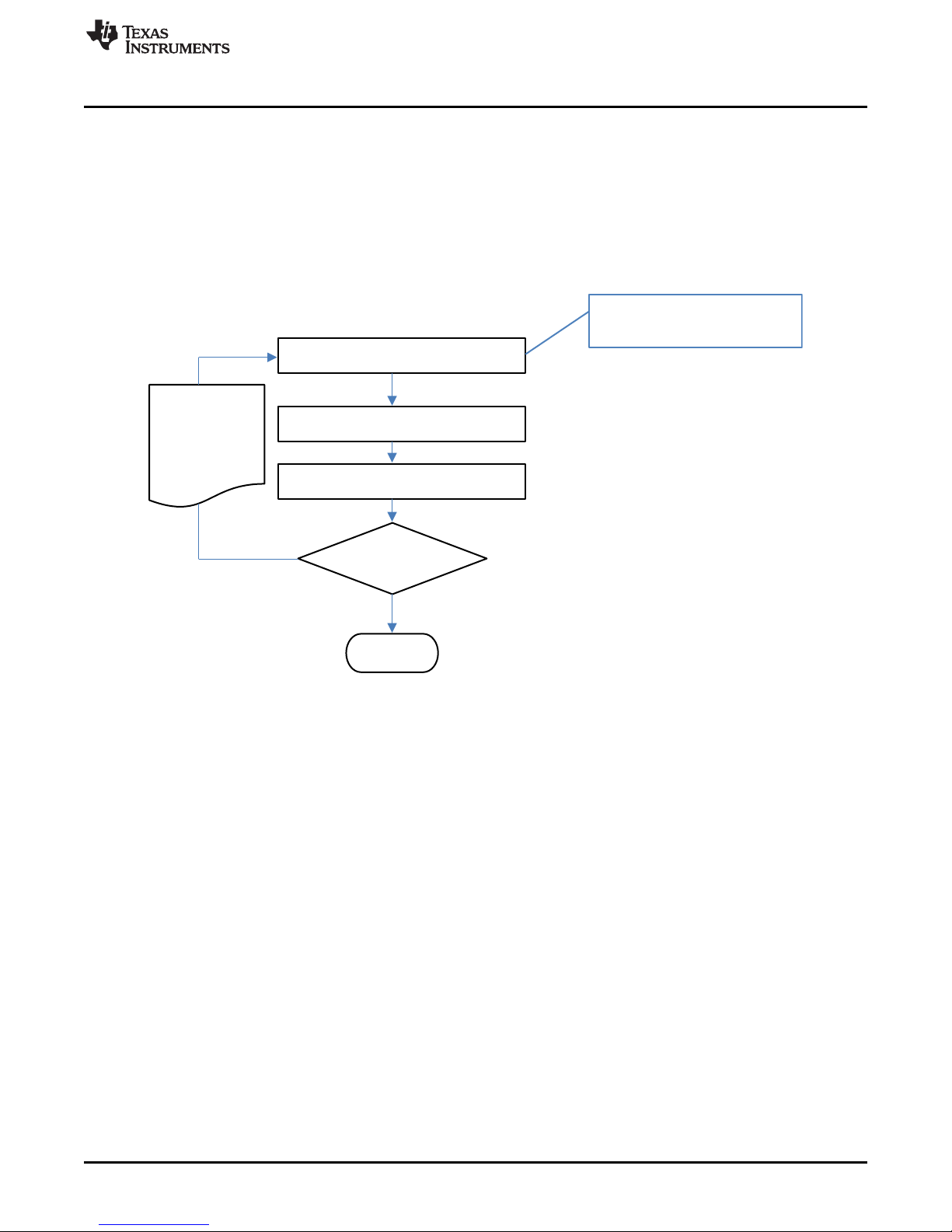
I2CWriteWord(0x0000, 0x0081,100)
ENTER_CAL MAC Command:
0x0081 to 0x0000
I2CWriteWord(0x0000, 0x0000,100)
I2CReadBlock(0x00, 2,100)
calMod == 1
Device did not
enter calibration
mode; retry
True
False
End
www.ti.com
6. Write calibration results to data flash.
3.3 Enter CALIBRATION Mode
The bq35100 device must be enabled (GE High) and in ACC mode (Operation Config A [GMSEL1:0] =
00) AND the GAUGE_START() command should have been sent. When using bqStudio, these steps are
automatic.
This sequence puts the gauge into CALIBRATION mode. These steps must be performed when the
gauge is in UNSEALED mode.
Enter CALIBRATION Mode
Figure 3-1. Enter CALIBRATION Mode Flow
SLUUBH1C–August 2016–Revised March 2018
Submit Documentation Feedback
Copyright © 2016–2018, Texas Instruments Incorporated
Factory Calibration
11
Page 12
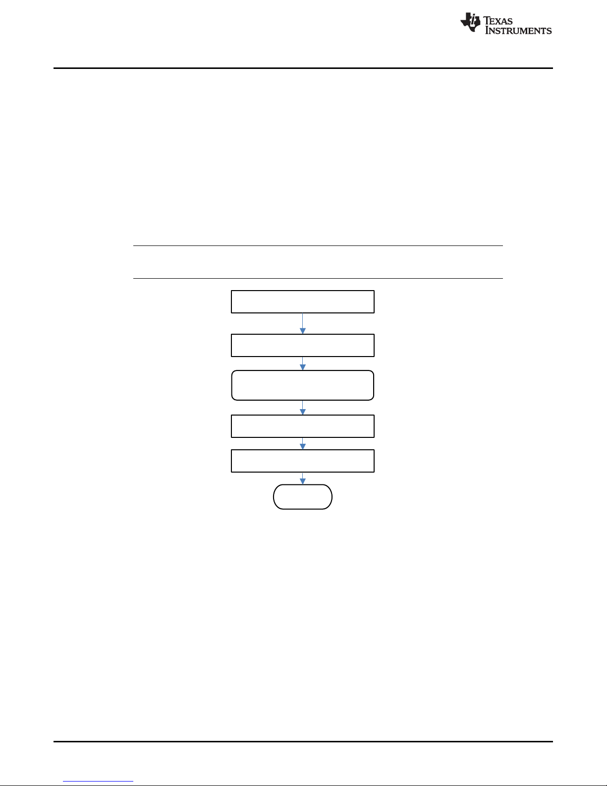
Apply known voltage
Voltage() = known voltage
End
int vOffset = Voltage()
– avgRawVoltage
Write vOffset to DF
Obtain avgRawVoltage
Voltage Calibration
3.4 Voltage Calibration
A known voltage must be applied to the device for voltage calibration, but the voltage can be measured in
two different ways. See Voltage for more details.
The bq35100 device is default-configured to use the BAT input for voltage measurement, and the data
used for calibration is made available through the calibration commands in units of millivolts (mV). In this
setup, the calculated voltage offset must be written to the corresponding location in DF. The voltage offset
is represented by an integer that is a single byte in size and can be written to the appropriate location in
DF without any intermediate steps. The host system must ensure that the fuel gauge is UNSEALED.
The device has the option to use an external voltage divider circuit where the voltage is measured through
the VIN pin, and the data used for calibration is made available through the calibration commands. In this
setup, there is no user offset required and the reported RawVoltage is actually RawADCounts. The gain
of the voltage translation circuit needs to be calculated and stored, where: V
65536. This resulting integer is written to VIN
NOTE: The step labeled Obtain avgRawVoltage refers to Section 3.7, Obtain Raw Calibration
Data.
Gain
www.ti.com
= (V
cellGain
/RawADCounts) ×
cal
.
12
Factory Calibration
Figure 3-2. Voltage Calibration Flow
SLUUBH1C–August 2016–Revised March 2018
Copyright © 2016–2018, Texas Instruments Incorporated
Submit Documentation Feedback
Page 13
I2CWriteWord (0x0000, 0x000A, 100)
CCA == 1
I2CReadBlock (0x00, 2, 100)
CCA == 0
Wait for CCA bit
to clear
End
Device is not calibrating
CC offset; retry.
The device is in the
process of calibrating
CC offset while the
CCA bit is set. Host
should check
the CCA bit more
than once every 0.5 s.
NOT
True
True
False
False
CC_OFFSET MAC Command:
0x000A to 0x0000
I2CWriteWord (0x0000, 0x0000, 100)
Enter Calibration Mode
Exit Calibration Mode
I2CWrite Word (0x0000, 0x000B, 100)
www.ti.com
3.5 CC Offset
Use MAC commands for CC Offset calibration. The host system does not need to write information to the
data flash (DF). See CONTROL_STATUS: 0x0000 for the description of the CONTROL_STATUS[CCA]
bit. The host system must ensure that the fuel gauge is UNSEALED.
NOTE: While the device is calibrating the CC Offset, the host system must not read the
CC Offset
CONTROL_STATUS register at a rate greater than once every 0.5 seconds and no current
should be flowing.
The step labeled Enter CALIBRATION Mode refers to Section 3.3, Enter CALIBRATION
Mode.
The step labeled Exit CALIBRATION Mode refers to Section 3.11, Exit CALIBRATION
Mode.
Figure 3-3. CC Offset Flow
SLUUBH1C–August 2016–Revised March 2018
Submit Documentation Feedback
Copyright © 2016–2018, Texas Instruments Incorporated
Factory Calibration
13
Page 14
I2CWriteWord(0x0000, 0x0009, 100)
CCA == 1 && BCA == 1
I2CReadBlock(0x00, 2, 100)
Wait for CCA bit
to clear
End
Device is not calibrating
CC offset; retry
The device is in the
process of calibrating
CC offset while the
CCA bit is set. The
CCA bit will clear and
then the device will
calibrate the board
offset. Host should
check the CCA/
BCA bits more than
once every 0.5 s.
NOT
True
True
False
False
BCA == 0
I2CWriteWord(0x0000, 0x0000, 100)
BOARD_OFFSET MAC Command:
0x0009 to 0x0000
Enter Calibration Mode
Exit Calibration Mode
Board Offset
3.6 Board Offset
Use MAC commands for Board Offset calibration. The host system does not need to write information to
the DF. The host system must ensure that the fuel gauge is UNSEALED. See CONTROL_STATUS:
0x0000 for the description of the CONTROL_STATUS[CCA] and [BCA] bits.
NOTE: While the device is calibrating the Board Offset, the host system should not read the
CONTROL_STATUS() register at a rate greater than once every 0.5 seconds and no current
should be flowing.
The step labeled Enter CALIBRATION Mode refers to Section 3.3, Enter CALIBRATION
Mode.
The step labeled Exit CALIBRATION Mode refers to Section 3.11, Exit CALIBRATION
Mode.
www.ti.com
14
Factory Calibration
Figure 3-4. Board Offset Flow
SLUUBH1C–August 2016–Revised March 2018
Copyright © 2016–2018, Texas Instruments Incorporated
Submit Documentation Feedback
Page 15

Analog Conversion Counter:
0x79
Read MSB and LSB of the raw data we
are interested in.
counterNow = Analog Conversion Counter
counterNow ==
counterPrev
True
False
End
Enter Calibration Mode
Wait 200 ms
loopCount = 0, rawDataSum = 0
counterNow = Analog Conversion Counter
counterPrev = counterNow
Analog Current:
0x7A, 0x7B (LSB, MSB)
*Analog Cell Voltage:
0x7C, 0x7D (LSB, MSB)
Analog Temperature:
0x7E, 0x7F (LSB, MSB)
rawDataSum + = (MSB << 8) + LSB
loopCount++
counterPrev = counterNow
loopCount <
samplesToAvg
True
avgRawData = rawDataSum/samplesToAvg
Exit Calibration Mode
* When measurement input is
- BAT, then units are millivolts.
- VIN, then units are RawADCounts.
www.ti.com
3.7 Obtain Raw Calibration Data
The following flowchart demonstrates how the host system obtains the raw data to calibrate current,
voltage, and temperature. The host system uses this flow in conjunction with the current, voltage, and
temperature flows described in this chapter. It is recommended that the host system samples the raw data
multiple times at a rate of once per second to obtain an average of the raw current, voltage, and
temperature. The host system must ensure that the fuel gauge is UNSEALED.
NOTE: The step labeled Enter CALIBRATION Mode refers to Section 3.3, Enter CALIBRATION
Mode.
The step labeled Exit CALIBRATION Mode refers to Section 3.11, Exit CALIBRATION
Mode.
Obtain Raw Calibration Data
Figure 3-5. Obtain Raw Calibration Data Flow
SLUUBH1C–August 2016–Revised March 2018
Submit Documentation Feedback
Copyright © 2016–2018, Texas Instruments Incorporated
Factory Calibration
15
Page 16

Force known load current
End
ccDelta = ccGain * 1,193,046
Typically 1000 mA
The signs of the variables are very
important. and
should be positive. ccOffset should be
treated as a 16-bit signed integer and
boardOffset should be an 8-bit signed
integer.
current avgRawCurrent
current = forced load current
Obtain CC Offset and Board offset
from DF
Obtain avgRawCurrent
The sign of current should be positive. Raw
current samples are positive in discharge
mode. This ensures that ccGain is positive.
Convert ccGain and ccDelta to
Gauge’s floating point
representation and write to DF
ccGain = current /(avgRawCurrent-(ccOffset + boardOffset) / 16)
Current Calibration
3.8 Current Calibration
CC Gain and CC Delta are two calibration parameters of concern for current calibration. A known load,
typically 1000 mA, is applied to the device during this process. Details on converting the CC Gain and CC
Delta to floating point format are in Floating Point Conversion. The host system must ensure that the fuel
gauge is UNSEALED.
NOTE: The step labeled Obtain avgRawCurrent refers to Section 3.7, Obtain Raw Calibration
Data.
The step labeled Convert ccGain and ccDelta to Gauge’s floating point representation
and write to DF refers to Section 3.10, Floating Point Conversion.
www.ti.com
Figure 3-6. Current Calibration Flow
16
Factory Calibration
SLUUBH1C–August 2016–Revised March 2018
Copyright © 2016–2018, Texas Instruments Incorporated
Submit Documentation Feedback
Page 17

Apply known temperature
temp = known temperature
End
int tOffset = temp - avgRawVoltage
Write tOffset to DF
Obtain avgRawTemp
www.ti.com
3.9 Temperature Calibration
This feature calibrates the internal temperature and the external temperature sensor if the source is set by
Operation Config A [TEMPS]. A known temperature must be applied to the device for temperature
calibration. The calculated temperature offset is written to the corresponding location in DF. The
temperature offset is represented by an integer that is a single byte in size and can be written to the
appropriate location in DF without any intermediate steps. The host system must ensure that the fuel
gauge is UNSEALED.
NOTE: a) The step labeled Obtain avgRawTemp refers to Section 3.7, Obtain Raw Calibration
Data.
b) When using bqStudio, ensure that the selected calibration of Internal or External
temperature matches the setting on the [TEMPS] selection.
Temperature Calibration
SLUUBH1C–August 2016–Revised March 2018
Submit Documentation Feedback
Figure 3-7. Temperature Calibration Flow
Copyright © 2016–2018, Texas Instruments Incorporated
Factory Calibration
17
Page 18

val < 0
mod _val = val
False
True
mod_val = val x (-1)
tmpVal = mod _val
False
True
byte2 = tmpVal LHS* of decimal
tmpVal = 2
8
× (tmpVal ± byte2)
False
byte1 = tmpVal LHS* of decimal
True
tmpVal = 28 × (tmpVal ± byte1)
decrement exp by 1
byte0 = tmpVal LHS* of decimal
False
True
True
Byte 2 OR with 0x80
False
True
False
rawData[byte0] = exp + 128
rawData[byte1] = byte2
rawData[byte2] = byte1
rawData[byte3] = byte0
exp < í128
End
val = read in value
Create integer, set to 0
exp = 0
tmpVal = tmpVal × (1+2
±25
)
tmpVal < 0.5
tmpVal < 0.5
multiply tmpVal by 2
tmpVal > = 1.0
tmpVal > = 1.0
divide tmpVal by 2
increment exp by 1
exp > 127
exp = 127
Write rawData [0-3] to
corresponding DF location
val < 0
tmpVal = 2
(8 ± exp)
× mod_val ± 128
exp í128
Floating Point Conversion
3.10 Floating Point Conversion
This section details how to convert the floating point CC Gain and CC Delta values to the format
recognized by the gauge.
18
Factory Calibration
* LHS is an abbreviation for Left-Hand Side. This refers to truncating the floating point value by removing anything to
the right of the decimal point.
Figure 3-8. Floating Point Conversion Flow
Copyright © 2016–2018, Texas Instruments Incorporated
www.ti.com
SLUUBH1C–August 2016–Revised March 2018
Submit Documentation Feedback
Page 19

I2CWriteWord(0x0000, 0x0080, 100)
EXIT_CAL MAC Command:
0x0080 to 0x0000
I2CWriteWord(0x0000, 0x0000, 100)
I2CReadBlock(0x00, 2, 100)
calMod == 0
Device did not
exit calibration
mode; retry
True
False
End
www.ti.com
3.11 Exit CALIBRATION Mode
This sequence takes the gauge out of CALIBRATION mode. These steps must be performed when the
gauge is in UNSEALED mode.
NOTE: It is recommended to reset the gauge after calibration is completed to ensure all
measurements are taken using the new calibration.
Exit CALIBRATION Mode
SLUUBH1C–August 2016–Revised March 2018
Submit Documentation Feedback
Copyright © 2016–2018, Texas Instruments Incorporated
Factory Calibration
19
Page 20

4.1 Operation Config A
Chapter 4
SLUUBH1C–August 2016–Revised March 2018
Basic Configuration
CLASS SUBCLASS NAME TYPE SIZE
Configuration Registers Operation Config A Hex 1 0x00 0xff 0x80 —
7 6 5 4 3 2 1 0
TEMPS EXTVCELL WRTEMP LF_EN RSVD GNDSEL GMSEL1 GMSEL0
LEGEND: R/W = Read/Write; R = Read only; -n = value after reset
MIN
VALUE
MAX
VALUE
DEFAULT
VALUE
TEMPS (Bit 7): Enables the external temperature sensor (TS)
1 = External Temperature Sensor is enabled.
0 = Internal temperature sensor is enabled.
EXTVCELL (Bit 6): Enables the external cell voltage translation measurement (VEN, VIN)
1 = External cell voltage translation measurement is used.
0 = Internal cell voltage translation measurement is used.
WRTEMP (Bit 5): Enables host to write the temperature to the gauge
1 = Enabled
0 = Disabled
LF_EN (Bit 4): Enables the Lifetime Data gathering feature
1 = Enabled
0 = Disabled
RSVD (Bit 3): Reserved. Do not use.
GNDSEL (Bit 2): Enables the use of SRN as GND for the ADC conversions
1 = ADC Ground is SRN.
0 = ADC Ground is SRP.
GMSEL1:0 (Bit 1, Bit 0): Enables specific gauging mode
0 0 = Enables ACCUMULATOR mode
0 1 = Enables STATE-OF-HEALTH VOLTAGE CORRELATION mode for LiMnO
1 0 = Enables END-OF-SERVICE RESISTANCE CORRELATION mode for LiSOCl
2
2
1 1 = Invalid setting, do not use.
UNIT
20
Basic Configuration
SLUUBH1C–August 2016–Revised March 2018
Copyright © 2016–2018, Texas Instruments Incorporated
Submit Documentation Feedback
Page 21

The bq35100 device can operate in three distinct modes: ACCUMULATOR (ACC) mode, STATE-OFHEALTH (SOH) mode, and END-OF-SERVICE (EOS) mode. The device can be configured and used for
only one of these modes in the field, as it is not intended to be able to actively switch between modes
when in normal use.
5.1 ACCUMULATOR Mode
In this mode, the bq35100 device measures and updates cell voltage, cell temperature, and load current
every 1 s and begins accumulating after GAUGE_START is received. This data is provided through the
I2C interface while ControlStatus() [GA] is set.
This mode is enabled when [GMSEL1:0] in Operation Config A = 00.
5.1.1 Total Capacity Update
When in ACCUMULATOR mode, the bq35100 device tracks and then stores the total accumulated
capacity to its internal data flash.
Chapter 5
SLUUBH1C–August 2016–Revised March 2018
Battery Gauging
Care should be taken when enabling and using this feature to ensure that the
maximum number of writes, which is 200,000, is not exceeded. For example,
this translates to no more than 25 writes per day over 20 years.
When the GE pin is asserted, the device will update AccumulatedCapacity() from the value stored in data
flash. When ControlStatus() [GA] is set, the device adds each coulomb counter measurement to the value
of AccumulatedCapacity().
Sending the GAUGE_STOP() command prior to the GE pin being pulled low initiates the latest value of
AccumulatedCapacity() to be written to data flash memory. As this operation takes a finite amount of time,
the gauge will assert [G_DONE] in ControlStatus() and can optionally trigger the ALERT pin to inform the
host when the operation is complete.
5.2 STATE-OF-HEALTH (SOH) Mode
This mode is enabled when [GMSEL1:0] in Operation Config A = 01. This mode is suitable for
determining SOH for Lithium Manganese Dioxide (LiMnO2) chemistry. In this mode, cell voltage and
temperature are precisely measured immediately after the GE pin is asserted. The gauge uses this data to
compute SOH.
SOH = DOD(TermV) – DOD(OCV, temperature)
Where:
TermV is a DF constant determined by the manufacturer to be discharge voltage below which the cell
cannot provide the power required by the device.
CAUTION
5.2.1 Low State-Of-Health Alert
BatteryStatus() [SOH_LOW] is set when StateOfHealth() is less than or equal to the value programmed in
SOHLOW for a period of SOH Set Time.
SLUUBH1C–August 2016–Revised March 2018
Submit Documentation Feedback
Copyright © 2016–2018, Texas Instruments Incorporated
Battery Gauging
21
Page 22

End-Of-Service (EOS) Mode
www.ti.com
CLASS SUBCLASS NAME TYPE SIZE
Configuration Discharge SOHLOW Integer 1 0 100 10 %
Configuration Discharge SOH Set Time Integer 1 0 60 0 s
Configuration Discharge
When BatteryStatus() [SOH_LOW] is set, the device can optionally trigger the ALERT pin. SOH_LOW is
cleared if StateOfHealth() is greater than SOH Clear Threshold. See Alert Signal for more information.
The GAUGE_START() and GAUGE_STOP() commands can be used in this mode to detect a Battery Low
Alert condition during a continuous discharge.
5.3 End-Of-Service (EOS) Mode
This mode is enabled when [GMSEL1:0] in Operation Config A = 10. This mode is suitable for gauging
Lithium Thionyl Chloride (LiSOCl2) cells. The End-Of-Service gauging algorithm uses voltage, current, and
temperature data to determine the resistance (R) and rate of change of resistance of the battery. The
resistance data is then used to find Depth of Discharge (DOD) = DOD(R). As above, SOH is determined
and in turn used to determine the EOS condition.
When in this mode, a GAUGE_START() command should be issued prior to any major discharge activity.
This will ensure that any major discharge pulses are used in the determination of the battery's condition.
Upon completion of any major discharge, the GAUGE_STOP() command should be sent to the device.
The gauge will continue to collect data in a low power state for the number of seconds determined by R
Data Seconds. The device then completes any calculations and flash writes. Once these tasks are
completed, then [G_DONE] is set and the device can be powered down.
SOH Clear
Threshold
MIN
VALUE
Integer 1 0 100 10 %
MAX
VALUE
DEFAULT
VALUE
UNIT
CLASS SUBCLASS NAME TYPE SIZE
EOS Data Values R Data Seconds U1 1 0 255 15 s
5.3.1 Initial EOS Learning
For optimal accuracy, the first event where the device updates its impedance value is required to be when
the battery is full (a fresh battery). If the battery was partially discharged, then the accuracy of the EOS
detection is compromised.
When a new battery is inserted, then the NEW_BATTERY() command should be sent to the device to
ensure the initial learned resistance RNEW is refreshed correctly.
In some cases, it may be necessary to compensate for anode passivation effects if there is a delay
between when the battery was conditioned for use and when the device is put into service. Several initial
impedance readings can be discarded (to remove passivation effects) by setting an appropriate value for
New Batt R Scale Delay.
CLASS SUBCLASS NAME TYPE SIZE
EOS Data Values
EOS Data Values R Table Scale Integer 2 –1 –1 –1 —
EOS Data Values
New batt R scale
delay
R Table Scale
Update Flag
MIN
VALUE
MIN
VALUE
Unsigned
Integer
Hex 1 0x00 0xff 0xff —
1 0 255 2 Readings
MAX
VALUE
MAX
VALUE
DEFAULT
VALUE
DEFAULT
VALUE
UNIT
UNIT
NOTE: Do not update R Table Scale and R TableScaleUpdateFlag.
22
Battery Gauging
SLUUBH1C–August 2016–Revised March 2018
Copyright © 2016–2018, Texas Instruments Incorporated
Submit Documentation Feedback
Page 23

www.ti.com
5.3.2 End-Of-Service Detection
The bq35100 device can detect when a sharp increase in the trend of tracked impedance occurs,
indicating that the battery is reaching its end-of-service condition.
When in this mode, each time the GAUGE_START() command is received, then the internal counter "EOS
Detection Pulse Count" is incremented. This internal value is stored to EOS Detection Pulse Count once
GAUGE_STOP() is received.
NOTE: EOS Detection Pulse Count must be programmed to 0 prior to final system installation.
When the device has enough information to update Impedance, the present value of Impedance is
copied to Previous Impedance in preparation for the new Impedance value to be updated.
Using this data, the device monitors the trend through a moving average algorithm. For improved
accuracy, it is recommended to gather new data on a fixed periodic base: for example, every 24 hours. As
the device is powered down when not needed for EOS monitoring, it has no "time" information.
There are two moving average trends that are calculated after an Impedance update:
Short Trend Average = Impedance × 1/DF1 + Previous Impedance × (1–1/DF1) (1)
Long Trend Average = Impedance × 1/DF2 + Previous Impedance × (1–1/DF2) (2)
Where:
DF1 (50) and DF2 (100) are the time constants of the moving average.
The trend detection equation is:
Short Trend Average > Long Trend Average × (1 + EOS Trent Detection / 100) (3)
When this occurs the Battery Status [EOS] flag is set and cannot be cleared.
Where:
EOS Trent Detection is the % increase of Short Trend Average over Long Trend Average.
For example: If EOS Trent Detection = 20, then the [EOS] flag is set when Short Trend Average is
120% × Long Trend Average.
End-Of-Service (EOS) Mode
CLASS SUBCLASS NAME TYPE SIZE
EOS Data Values R short trend filter Unsigned Int 1 1 255 251 —
EOS Data Values R long trend filter Unsigned Int 1 1 255 253 —
EOS Data Values EOS trend detection Unsigned Int 1 1 100 20 —
EOS Data Values EOS detection pulse count Unsigned Int 2 1 20000 120 —
EOS Data Values
EOS Data Values Short trend average Unsigned Int 4 1 8355712 0 —
EOS Data Values Long trend average Unsigned Int 4 1 8355712 0 —
EOS detection pulse count
Thrhd
5.3.3 End-Of-Service Smoothing
In EOS mode, the State-Of-Health() output is smoothed to provide a more stable output value that will
converge, and not jump, at the terminate voltage. Smoothing occurs when Voltage() < EOS SOH Smooth
Start Voltage. The value of EOS SOH Smooth Start Voltage must be higher than Cell Terminate
Voltage.
NOTE: When EOS Smoothing is enabled, Lifetime Data gathering must also be enabled. This can
be done by sending (Control() 0x002E [LT_EN]) and confirming that it is enabled when
OperationStatus()[LTEN] = 1.
In EOS mode, the accuracy of the SOH reported value can vary significantly with a load
profile. Perform in-system evaluation to determine the reported value at the desired EOS
level. In some instances, the value of SOH should be ignored.
MIN
VALUE
Unsigned Int 2 1 20000 120 —
MAX
VALUE
DEFAULT
VALUE
UNIT
SLUUBH1C–August 2016–Revised March 2018
Submit Documentation Feedback
Copyright © 2016–2018, Texas Instruments Incorporated
Battery Gauging
23
Page 24

End-Of-Service (EOS) Mode
The Smoothing Margin can be set to control the rate of smoothing, but it is recommended to not change
it.
www.ti.com
CLASS SUBCLASS NAME TYPE SIZE
Gas Gauging Design
EOS Values
EOS Data Values
Cell Terminate
Voltage
EOS SOH Smooth
Start Voltage
EOS SOH
Smoothing Margin
Integer 2 0 5000 2900 mV
Integer 2 0 5000 2800 mV
Integer 1 0 255 128
MIN
VALUE
MAX
VALUE
DEFAULT
VALUE
UNIT
24
Battery Gauging
SLUUBH1C–August 2016–Revised March 2018
Copyright © 2016–2018, Texas Instruments Incorporated
Submit Documentation Feedback
Page 25

System Current
0
GE LOW
GE HIGH
The bq35100 device has only one active power mode that is enabled through the GAUGE ENABLE (GE)
pin. The power consumption of the bq35100 device can change significantly based on host commands
that it receives and its default configuration, specifically with respect to data flash updates.
6.1 Device Functional Modes
The bq35100 device is intended for systems where the battery electronics are required to consume a very
low average current. To achieve this, the device is intended to be fully powered off when not required
through control of the GAUGE ENABLE pin.
When this pin is low, then the device is fully powered down where no measurements are made and no
data, unless in flash, is retained. In this state, the power consumption of the device is a few 10s of nA.
This value is primarily leakage of the device and other components on the board, but also includes
measurement errors. Due to the level of possible variations, use a conservative value of 50 nA for
example calculations.
An example system current profile is shown along with the state of GE to reduce the average power
consumption of the battery electronics.
Chapter 6
SLUUBH1C–August 2016–Revised March 2018
Power Control
Figure 6-1. System Current Profile Example
The average power consumption of the bq35100 device is an average of the periods where GAUGE
ENABLE is high AND low over a given period.
For example, if the system enters a high power state (315 µA) for 30 s every 4 hours, the average current
will be:
315 µA × 30 s / 4 hrs = 0.66 µA (4)
When GAUGE ENABLE is low (GE = Low), then the device is powered off and the current is nominally
I
CC_GELOW
and is the leakage current into the REGIN pin. Other components connected to this node should
also be evaluated to determine the "System Off" current total.
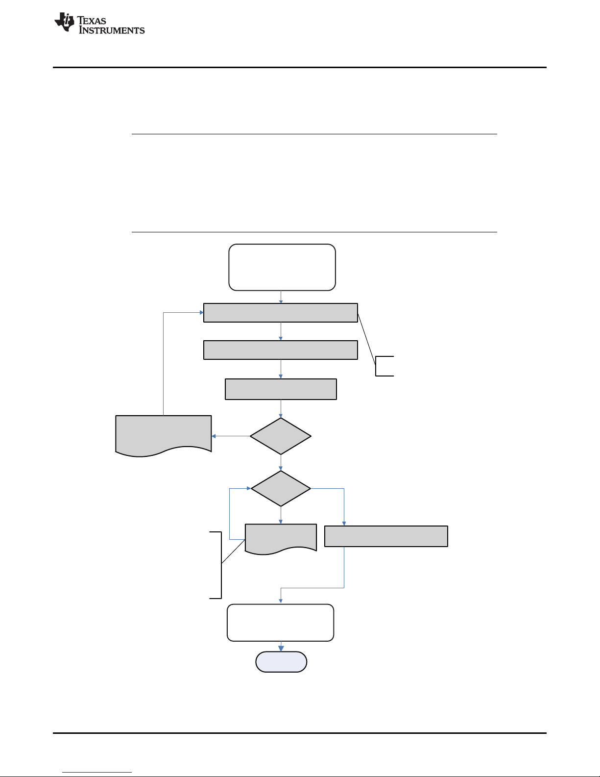
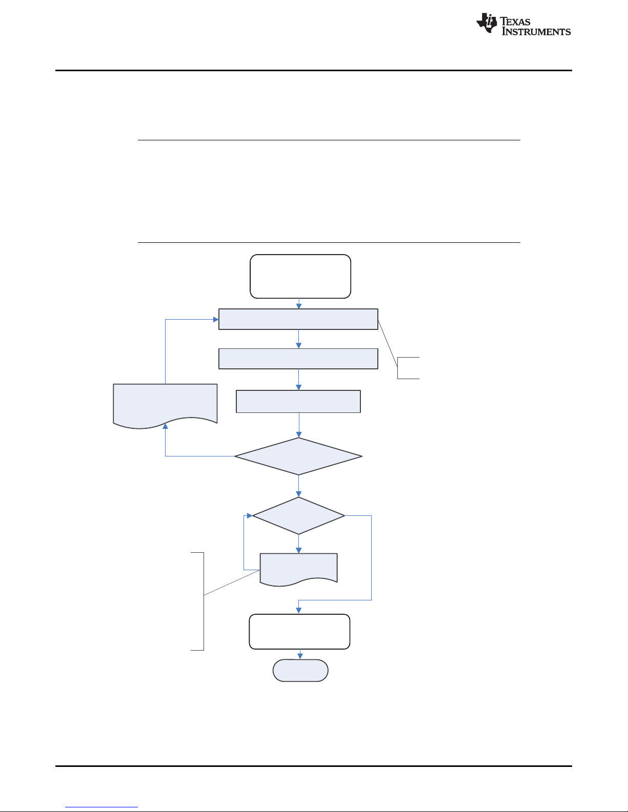
When the device is used for gas gauging, it transitions through several power states based on the
selection of Operation Cfg A[GMSEL].
Figure 6-2 highlights the operational flow and conditional decisions.
SLUUBH1C–August 2016–Revised March 2018
Submit Documentation Feedback
Copyright © 2016–2018, Texas Instruments Incorporated
Power Control
25
Page 26

Systems wants to
begin monitoring
KEY:
GE = GAUGE ENABLE Pin
Host sets GE High
YES
YES
Take initial
measurements and
check for warnings
Set INITCOMP= 1
RX ‘START’ CMD
from Host
Startup Phase
NO
Is GMSEL= 10
NO
Update Discharge
Accumulation from
Coulomb Counter
Update Voltage and
Temperature
RX ‘STOP’ CMD
from Host
Update Voltage and
Current with128 ×
8-ms conversions
Check for Warnings
and update status
YES
Execute End of
Service detection
algorithm and
update status
NO
Execute Lifetime
Checks
Is GMSEL= 10
Write Accumulated
data and status to
DF
YES
NO
Are DF updates
Enabled?
Are Lifetime
updates
Enabled?
YES
NO
Update Lifetime DF
YES
Set G_DONE = 1
Device OK to
power Down
Active
Phase
Data Update
Phase
Waiting Phase
Device powers up
NO
Update Voltage
Device Functional Modes
www.ti.com
26
Power Control
Figure 6-2. Operational Flow
Copyright © 2016–2018, Texas Instruments Incorporated
SLUUBH1C–August 2016–Revised March 2018
Submit Documentation Feedback
Page 27

www.ti.com
6.2 Flash Updates
If enabled, data flash can only be updated if either of the two following conditions is true:
1. ControlStatus() [GA] = 1 AND Voltage() ≥ Flash Update OK Voltage.
2. ControlStatus() [GA] = 0.
If enabled, data flash can only be updated if Voltage() ≥ Flash Update OK Voltage. Flash programming
current can cause an increase in LDO dropout. The value of Flash Update OK Voltage should be
selected such that the device VCCvoltage does not fall below its minimum of 2.4 V during Flash write
operations.
Flash Updates
CLASS SUBCLASS NAME TYPE SIZE
Configuration Power
Flash Update OK
Voltage
Integer 2 0 4200 2800 mV
MIN
VALUE
MAX
VALUE
DEFAULT
VALUE
UNIT
SLUUBH1C–August 2016–Revised March 2018
Submit Documentation Feedback
Copyright © 2016–2018, Texas Instruments Incorporated
Power Control
27
Page 28

7.1 Battery Low Warning
The bq35100 device can indicate and optionally trigger the ALERT pin when the primary battery voltage
falls below a programmable threshold.
STATUS CONDITION ACTION
Normal Voltage() > BatLow Voltage Set Threshold BatteryAlert()[BATLOW] = 0
Trip
Voltage() ≤ BatLow Voltage Set Threshold for
BATLOW:Delay duration BatLow Voltage Set Time
Chapter 7
SLUUBH1C–August 2016–Revised March 2018
Battery Condition Warnings
BatteryAlert()[BATLOW] = 1
CLASS SUBCLASS NAME TYPE SIZE
Configuration Discharge
Configuration Discharge
7.2 Temperature Low Warning
The bq35100 device can indicate and optionally trigger the ALERT pin when the primary battery
temperature falls below a programmable threshold.
Status Condition Action
Normal Temperature() > Under Temperature Set Threshold BatteryAlert()[TEMPLOW] = 0
Trip
Recovery
CLASS SUBCLASS NAME TYPE SIZE
Configuration Discharge
Configuration Discharge
Configuration Discharge
Temperature() ≤ Under Temperature Threshold for
TEMPLOW:Delay duration for Under Temperature
Set Time duration
Temperature() > Under Temperature Clear
Threshold
BatLow Voltage Set
Threshold
BatLow Voltage Set
Time
Under Temperature
Set Threshold
Under Temperature
Set Time
Under Temperature
Clear Threshold
MIN
VALUE
Integer 2 0 5000 2800 mV
Integer 1 0 255 10 s
BatteryAlert()[TEMPLOW] = 1
BatteryAlert()[TEMPLOW] = 0
MIN
VALUE
Signed
Integer
Integer 1 0 255 4 s
Integer 2 0 255 100 0.1°K
2 –400 850 –200 0.1°K
MAX
VALUE
MAX
VALUE
DEFAULT
VALUE
DEFAULT
VALUE
UNIT
UNIT
7.3 Temperature High Warning
The bq35100 device can indicate and optionally trigger the ALERT pin when the primary battery
temperature rises above a programmable threshold.
28
Battery Condition Warnings
SLUUBH1C–August 2016–Revised March 2018
Copyright © 2016–2018, Texas Instruments Incorporated
Submit Documentation Feedback
Page 29

www.ti.com
Battery Low SOC Warning
STATUS CONDITION ACTION
Normal Temperature() < OT Dsg Threshold BatteryAlert()[TEMPHIGH] = 0
Trip
Recovery Temperature() < OT Dsg Recovery BatteryAlert()[TEMPHIGH] = 0
Temperature() ≥ OT Dsg Threshold for OT Dsg Time
duration
BatteryAlert()[TEMPHIGH] = 1
CLASS SUBCLASS NAME TYPE SIZE
Configuration Discharge OT Dsg
Configuration Discharge OT Dsg Time Integer 2 0 255 4 s
Configuration Discharge OT Dsg Recovery Integer 2 0 255 100 0.1°K
Signed
Integer
2 –400 850 450 0.1°K
MIN
VALUE
MAX
VALUE
DEFAULT
VALUE
7.4 Battery Low SOC Warning
The bq35100 device can indicate and optionally trigger the ALERT pin when the primary battery state-ofhealth (SOH) falls below a programmable threshold.
STATUS CONDITION ACTION
Normal StateOfHealth() > SOH Low BatteryStatus()[SOHLOW] = 0
Trip StateOfHealth() ≤ SOH Low BatteryStatus()[SOHLOW] = 1
CLASS SUBCLASS NAME TYPE SIZE
Configuration Discharge SOH Low
Configuration Discharge SOH Set Time
Configuration Discharge
SOH Clear
Threshold
Signed
Integer
Signed
Integer
Signed
Integer
MIN
VALUE
1 0 100 10 %
1 0 100 10 %
1 0 100 10 %
MAX
VALUE
DEFAULT
VALUE
UNIT
UNIT
7.5 Battery EOS OCV BAD Warning
The device assumes that when GE is asserted, the cell is at rest and uses the initialization voltage reading
to determine the Open Circuit Voltage (OCV). If the cell was not fully relaxed at that point, then the voltage
after the pulse could rise above the OCV. This causes an incorrect impedance to be calculated.
If the device measures a voltage value above the initial OCV, then it increments an internal counter. When
this counter increments up to EOS Relax V Hi Max Counts, then [EOS_OCV_BAD] is set in
CONTROL_STATUS().
If [EOS_OCV_BAD] becomes set, then the battery requires a longer time to rest and the device should be
powered down (GE driven low). As a guideline, from the last major discharge, a rest of 5 hours should
allow full relaxation.
CLASS SUBCLASS NAME TYPE SIZE
EOS Data Values
EOS Relax V
Hi Max Counts
Integer 1 1 255 3 counts
MIN
VALUE
MAX
VALUE
DEFAULT
VALUE
UNIT
SLUUBH1C–August 2016–Revised March 2018
Submit Documentation Feedback
Copyright © 2016–2018, Texas Instruments Incorporated
Battery Condition Warnings
29
Page 30

Chapter 8
SLUUBH1C–August 2016–Revised March 2018
ALERT Signal
The ALERT signal can be configured to be triggered by a variety of status conditions. When the ALERT
Configuration bit is set AND the corresponding bit in BatteryStatus() or ControlStatus() is set, then the
corresponding BatteryAlert() bit is set, triggering the ALERT signal.
For example: If BatteryStatus() [BATLOW] AND ALERT Configuration [BATLOW] = 1, then
BatteryAlert() [BATLOW] is set and the ALERT pin is triggered.
The ALERT signal is cleared upon a read of BatteryStatus().
Table 8-1. Data Flash ALERT Configuration
CLASS SUBCLASS NAME TYPE SIZE
Configuration Registers ALERT Configuration Hex 1 0x00 0xff 0x00 —
7 6 5 4 3 2 1 0
BATLOW TEMPLOW TEMPHIGH SOH_LOW EOS RSVD G_DONE INITCOMP
LEGEND: R/W = Read/Write; R = Read only; -n = value after reset
MIN
VALUE
MAX
VALUE
DEFAULT
VALUE
BATLOW (Bit 7): Battery voltage low condition
0 = ALERT is not triggered when BATLOW becomes set (default).
1 = ALERT is triggered when BATLOW becomes set.
TEMPLOW (Bit 6): Battery temperature low condition
0 = ALERT is not triggered when TEMPLOW becomes set (default).
1 = ALERT is triggered when TEMPLOW becomes set.
TEMPHIGH (Bit 5): Battery temperature high condition
0 = ALERT is not triggered when TEMPHIGH becomes set (default).
1 = ALERT is triggered when TEMPHIGH becomes set.
SOH_LOW (Bit 4): Low SOH State detected
0 = ALERT is not triggered when SOH_LOW becomes set (default).
1 = ALERT is triggered when SOH_LOW becomes set.
EOS (Bit 3): End-Of-Service state detected
0 = ALERT is not triggered when EOS becomes set (default).
1 = ALERT is triggered when EOS becomes set.
RSVD (Bit 2): Reserved. Do not use.
G_DONE (Bit 1): Gauge Done State reached
0 = ALERT is not triggered when G_DONE becomes set (default).
1 = ALERT is triggered when G_DONE becomes set.
INITCOMP (Bit 0): Initialization Complete
0 = ALERT is not triggered when INITCOMP becomes set (default).
1 = ALERT is triggered when INITCOMP becomes set.
UNIT
30
ALERT Signal
SLUUBH1C–August 2016–Revised March 2018
Copyright © 2016–2018, Texas Instruments Incorporated
Submit Documentation Feedback
Page 31

Chapter 9
SLUUBH1C–August 2016–Revised March 2018
Lifetime Data Collection
The bq35100 device can be enabled by writing to Control() 0x002E [LT_EN] to gather data regarding the
primary battery and to store it to data flash.
The following data is collected in RAM and only written to DF when the host sends the End command to
the device.
• Min and Max Cell Voltage
• Min and Max Discharge Current
• Min and Max Temperature
CLASS SUBCLASS NAME TYPE MIN MAX DEFAULT UNIT
LTFlash Voltage Max I2 0 32767 0 mV
LTFlash Voltage Min I2 0 32767 0 mV
LTFlash Current Max Discharge I2 0 32767 0 mA
LTFlash Current Min Discharge I2 0 32767 0 mA
LTFlash Temperature Max Cell I2 –128 127 0 °C
LTFlash Temperature Min Cell I2 –128 127 0 °C
LTFlash Temperature Max Gauge I2 –128 127 0 °C
LTFlash Temperature Min Gauge I2 –128 127 0 °C
SLUUBH1C–August 2016–Revised March 2018
Submit Documentation Feedback
Copyright © 2016–2018, Texas Instruments Incorporated
Lifetime Data Collection
31
Page 32

10.1 Overview
As of March 2012, the latest revision is FIPS 180-4. SHA-1, or secure hash algorithm, is used to compute
a condensed representation of a message or data also known as hash. For messages < 264, the SHA-1
algorithm produces a 160-bit output called a digest.
In a SHA-1 one-way hash function, there is no known mathematical method of computing the input given,
only the output. The specification of SHA-1, as defined by FIPS 180-4, states that the input consists of
512-bit blocks with a total input length less than 264 bits. Inputs that do not conform to integer multiples of
512-bit blocks are padded before any block is input to the hash function. The SHA-1 algorithm outputs the
160-bit digest.
The device generates a SHA-1 input block of 288 bits (total input = 160-bit message + 128-bit key). To
complete the 512-bit block size requirement of the SHA-1 function, the device pads the key and message
with a 1, followed by 159 0s, followed by the 64-bit value for 288 (000...00100100000), which conforms to
the pad requirements specified by FIPS 180-4.
• http://www.nist.gov/itl/
• http://csrc.nist.gov/publications/fips
• www.faqs.org/rfcs/rfc3174.html
Chapter 10
SLUUBH1C–August 2016–Revised March 2018
SHA-1 Authentication
10.2 HMAC Description
The SHA-1 engine calculates a modified HMAC value. Using a public message and a secret key, the
HMAC output is considered to be a secure fingerprint that authenticates the device used to generate the
HMAC.
To compute the HMAC: Let H designate the SHA-1 hash function, M designate the message transmitted
to the device, and KD designate the unique 128-bit Unseal/Full Access/Authentication key of the device.
HMAC(M) is defined as: H[KD || H(KD || M)], where || symbolizes an append operation.
10.3 Authentication
The authentication feature is used in the following sequence:
1. MAC command 0x0000: Command = 0x0000, write the 20 bytes to 0x40, then write the checksum+len
at 0x60. The response will be available as a MAC response, so 0x3E/0x3F will be 0x0000, 0x40 will
have the SHA1 result, and 0x60/0x61 will have the checksum and length.
2. Generate 160-bit message M using a random number generator that meets approved random number
generators described in FIPS PUB 140–2.
3. Generate SHA-1 input block B1 of 512 bytes (total input = 128-bit authentication key KD + 160-bit
message M + 1 + 159 0s + 100100000).
4. Generate SHA-1 hash HMAC1 using B1.
5. Generate SHA-1 input block B2 of 512 bytes (total input = 128-bit authentication key KD + 160-bit hash
HMAC1 + 1 + 159 0s + 100100000).
6. Generate SHA-1 hash HMAC2 using B2.
7. With no active MACData() data waiting, write 160-bit message M to MACData() in the format
0xAABBCCDDEEFFGGHHIIJJKKLLMMNNOOPPQQRRSSTT, where AA is LSB.
8. Wait 250 ms, then read MACData() for HMAC3.
32
SHA-1 Authentication
SLUUBH1C–August 2016–Revised March 2018
Copyright © 2016–2018, Texas Instruments Incorporated
Submit Documentation Feedback
Page 33

www.ti.com
9. Compare host HMAC2 with device HMAC3, and if it matches, both host and device have the same key
KD and the device is authenticated.
10.4 AuthenticateData(): 0x40…0x53
UNSEALED Access—This data block has a dual function: It is used for the authentication challenge and
response and is part of the 32-byte data block when accessing data flash.
SEALED Access—This data block has a dual function: It is used for authentication challenge and
response, and is part of the 32-byte data block when accessing Manufacturer Data.
10.5 AuthenticateChecksum(): 0x54
UNSEALED Access—This byte holds the authentication checksum when writing the authentication
challenge to the device, and is part of the 32-byte data block when accessing data flash.
SEALED Access—This byte holds the authentication checksum when writing the authentication challenge
to the device, and is part of the 32-byte data block when accessing Manufacturer Data.
AuthenticateData(): 0x40…0x53
SLUUBH1C–August 2016–Revised March 2018
Submit Documentation Feedback
Copyright © 2016–2018, Texas Instruments Incorporated
SHA-1 Authentication
33
Page 34

11.1 Command Summary
Chapter 11
SLUUBH1C–August 2016–Revised March 2018
Data Commands
Table 11-1. Data Command Summary
CMD MODE NAME FORMAT
0x00...0x01 R/W Control Hex 2 0x00 0xff — —
0x02…0x05 R AccumulatedCapacity Signed Int 4 0 4.29E9 — µAh
0x06…0x07 R Temperature
0x08...0x09 R Voltage Signed Int 2 0 65535 — mV
0x0A R BatteryStatus Hex 1 0x00 0xff — —
0x0B R BatteryAlert Hex 1 0x00 0xff — —
0x0C…0x0D R Current Signed Int 2 –32768 32767 — mA
0x16…0x17 R Scaled R
0x22…0x23 R Measured Z
0x28…0x29 R InternalTemperature
0x2E R StateOfHealth
0x3C…0x3D R DesignCapacity
0x79 R Cal_Count Hex 1 0x00 0xff — —
0x7A…0x7B R Cal_Current Signed Int 2 0 65535 — mA
0x7C…0x7D R Cal_Voltage Signed Int 2 0 32767 —
0x7E…0x7F R Cal_Temperature
(1)
mV when [EXTVCELL] = 0 and ADC counts when [EXTVCELL] = 1
Unsigned
Int
Unsigned
Int
Unsigned
Int
Unsigned
Int
Unsigned
Int
Unsigned
Int
Unsigned
Int
SIZE IN
BYTES
2 –32768 32767 — 0.1°K
2 0 65535 — mΩ
2 0 65535 — mΩ
2 –32768 32767 — 0.1°K
1 0 100 — %
2 0 65535 — mAh
2 0 65535 — °K
MIN
VALUE
MAX
VALUE
DEFAULT
VALUE
UNIT
mV or
Counts
(1)
11.2 Control(): 0x00/0x01
Issuing a Control() (or Manufacturer Access Control or MAC) command requires a 2-byte subcommand.
The subcommand specifies the particular MAC function desired. The Control() command enables the
system to control specific features of the gas gauge during normal operation and additional features when
the device is in different access modes, as described below. On this device, Control() commands may
also be sent to ManufacturerAccessControl().
Any subcommand that has a data response will be read back on MACData(). Reading the Control()
registers will always report the CONTROL_STATUS() data field, except after the DEVICE_TYPE() and
FW_VERSION() subcommands. After these subcommands, CONTROL_STATUS() will report the value
0xFFA5 one time before reverting to the normal data response. This is a flag to indicate that the data
response has been moved to MACData(). Writing a 0x0000 to Control() is not necessary to read the
CONTROL_STATUS(); however, doing so is okay.
34
Data Commands
SLUUBH1C–August 2016–Revised March 2018
Copyright © 2016–2018, Texas Instruments Incorporated
Submit Documentation Feedback
Page 35

www.ti.com
When executing commands that require data (such as data flash writes), the subcommand can be written
to either Control() or ManufacturerAccessControl() registers; however, it is recommended to write using
the ManufacturerAccessControl() registers as this enables performing the full command in a single I2C
transaction.
For example, the following return the same CHEM_ID data write:
0x0000 0x0800 ;
Read: 0x3e
Read: 0x3f
write: 0x3e 0x0800 ;
Read: 0x3e
Read: 0x3f
The Control() MAC command enables the host to control specific features of the device during normal
operation, and additional features when the bq35100 device is in different access modes, as described in
Table 11-2.
CONTROL_STATUS: 0x0000
Table 11-2. Control MAC Subcommands
CNTL FUNCTION CNTL DATA
CONTROL_STATUS 0x0000 Yes Reports the status of key features
DEVICE_TYPE 0x0001 Yes Reports the device type of 0x100 (indicating bq35100)
FW_VERSION 0x0002 Yes Reports the firmware (LSB) version on the device type
HW_VERSION 0x0003 Yes Reports the hardware (MSB) version of the device type
STATIC_CHEM_CHKSUM 0x0005 Yes Calculates chemistry checksum
CHEM_ID 0x0006 Yes
PREV_MACWRITE 0x0007 Yes Returns previous Control() command code
BOARD_OFFSET 0x0009 Yes
CC_OFFSET 0x000A Yes Forces the device to measure the internal CC offset
CC_OFFSET_SAVE 0x000B Yes Forces the device to store the internal CC offset
GAUGE_START 0x0011 Yes Triggers the device to enter ACTIVE mode
GAUGE_STOP 0x0012 Yes
SEALED 0x0020 No Places the device in SEALED access mode
CAL_ENABLE 0x002D No Toggle CALIBRATION mode enable
LT_ENABLE 0x002E No Enables Lifetime Data collection
RESET 0x0041 No Forces a full reset of the device
EXIT_CAL 0x0080 No Exit CALIBRATION mode
ENTER_CAL 0x0081 No Enter CALIBRATION mode
NEW_BATTERY 0xA613 Yes
SEALED
ACCESS
DESCRIPTION
Reports the chemical identifier used by the gas gauge
algorithms
Forces the device to measure and store the board
offset
Triggers the device to stop gauging and complete all
outstanding tasks
Used to refresh the gauge when a new battery is
installed and resets all recorded data.
11.3 CONTROL_STATUS: 0x0000
This command instructs the device to return status information to Control addresses 0x00/0x01. The
status word includes the following information.
SLUUBH1C–August 2016–Revised March 2018
Submit Documentation Feedback
Copyright © 2016–2018, Texas Instruments Incorporated
Data Commands
35
Page 36

CONTROL_STATUS: 0x0000
15 14 13 12 11 10 9 8
FLASHF SEC1 SEC0 CalMode BCA CCA LTEN OCVFAIL
7 6 5 4 3 2 1 0
INITCOMP G_DONE SOH_ERR SOH_MERIT
LEGEND: R/W = Read/Write; R = Read only; -n = value after reset
EOS_BAD
_OCV
RSVD RSVD GA
FLASHF (Bit 15): Indicates the device has detected a failed write to data flash.
1 = Active
0 = Inactive
SEC1, SEC0 (Bit 14,13): Indicates which SECURITY mode the device is in 0.
0, 0 = Reserved
0, 1 = Full Access
1, 0 = Unsealed
1, 1 = Sealed
CalMode (Bit 12): Indicates the device is in CALIBRATION mode.
1 = Active
0 = Inactive
BCA (Bit 11): Indicates the device Board Calibration routine is active.
1 = Active
0 = Inactive
CCA (Bit 10): Indicates the device Coulomb Counter Calibration routine is active.
1 = Active
0 = Inactive
LTEN (Bit 9): Indicates that Lifetime Data collection has been enabled.
1 = Enabled
0 = Disabled
OCVFAIL (Bit 8): Indicates if too much current is detected when making the initial voltage measurement.
1 = Too much current detected
0 = Voltage measurement OK
INITCOMP (Bit7): Indicates the device initialization is complete.
1 = Initialization is complete.
0 = Initialization is not complete.
G_DONE (Bit 6): Indicates all tasks are complete and the device can be powered down.
1 = All tasks are complete.
0 = Some tasks have yet to complete.
SOH_ERR (Bit 5): Indicates the quality of the SOH calculation has overflowed.
1 = SOH Calculation has overflowed.
0 = SOH calculation has not overflowed.
SOH_MERIT (Bit 4): Indicates the quality of the SOH calculation was limited.
1 = SOH Calculation Limited
0 = SOH calculation was not limited.
EOS_BAD_OCV (Bit 3): Indicates the measured voltage exceeds the initial OCV voltage.
1 = Bad OCV measurements are made.
0 = Good OCV measurements are made.
GA (Bit 0): Indicates the device is in ACTIVE mode.
www.ti.com
36
Data Commands
SLUUBH1C–August 2016–Revised March 2018
Copyright © 2016–2018, Texas Instruments Incorporated
Submit Documentation Feedback
Page 37

www.ti.com
1 = Active
0 = Inactive
11.3.1 DEVICE_TYPE: 0x0001
When reading DEVICE_TYPE(), a block read is used. This requires that a write to 0x00 of 0x0200 should
be followed by a read of 0x40 with 6 bytes to be read out. All In little-endian order, the first 2 bytes are
DEVICE_TYPE(), then 2 bytes of FW_VERSION() and 2 bytes of FW BUILD.
11.3.2 FW_VERSION: 0x0002
When reading FW_VERSION(), a block read is used. This requires that a write to 0x00 of 0x0200 should
be followed by a read of 0x40 with 6 bytes to be read out. All in little-endian order, the first 2 bytes are
DEVICE_TYPE(), then 2 bytes of FW_VERSION() and 2 bytes of FW BUILD.
11.3.3 HW_VERSION: 0x0003
This command instructs the device to return the hardware version to addresses 0x00/0x01.
11.3.4 STATIC_CHEM_DF_CHKSUM: 0x0005
This command instructs the fuel gauge to calculate chemistry checksum as a 16-bit unsigned integer sum
of all static chemistry data. The most significant bit (MSB) of the checksum is masked yielding a 15-bit
checksum. This checksum is compared with the value stored in the data flash Static Chem DF
Checksum. If the value matches, the MSB will be cleared to indicate a pass. If it does not match, the
MSB will be set to indicate a failure.
CONTROL_STATUS: 0x0000
11.3.5 CHEM_ID: 0x0006
This command instructs the fuel gauge to return the chemical identifier for the programmed chemistry
configuration to addresses 0x00/0x01. For evaluation purposes, the default CHEM_ID is a hybrid of a) Ra
table for LiSOCl2and b) OCV table for LiMnO2. The appropriate Chem ID for the cell to be used in the
target application should be used in production.
11.3.6 PREV_MACWRITE: 0x0007
This command instructs the fuel gauge to return the previous command written to addresses 0x00/0x01.
The value returned is limited to less than 0x0020.
11.3.7 BOARD_OFFSET: 0x0009
This command instructs the fuel gauge to calibrate board offset when is in ACTIVE mode. During board
offset calibration, the [BCA] bit is set. This command only returns updated data after GAUGE_START() is
received and prior to when GAUGE_STOP() is received.
11.3.8 CC_OFFSET: 0x000A
This command instructs the fuel gauge to calibrate the coulomb counter offset when in ACTIVE mode.
During calibration, the [CCA] bit is set. This command only returns updated data after GAUGE_START() is
received and prior to when GAUGE_STOP() is received.
11.3.9 CC_OFFSET_SAVE: 0x000B
This command instructs the fuel gauge to save the coulomb counter offset after calibration when it is in
ACTIVE mode.
11.3.10 GAUGE_START: 0x0011
This command instructs the fuel gauge to enter ACTIVE mode.
SLUUBH1C–August 2016–Revised March 2018
Submit Documentation Feedback
Copyright © 2016–2018, Texas Instruments Incorporated
Data Commands
37
Page 38

CONTROL_STATUS: 0x0000
11.3.11 GAUGE_STOP: 0x0012
This command instructs the fuel gauge to exit ACTIVE mode and complete all tasks.
11.3.12 SEALED: 0x0020
This command instructs the fuel gauge to transition from UNSEALED state to SEALED state. The fuel
gauge should always be set to SEALED state for use in the customer’s end equipment.
11.3.13 CAL_ENABLE: 0x002D
This command instructs the fuel gauge to enable entry and exit to CALIBRATION mode.
11.3.14 LT_ENABLE: 0x002E
This command instructs the fuel gauge to enable Lifetime Data collection.
11.3.15 RESET: 0x0041
This command instructs the fuel gauge to perform a full reset. This command is only available when the
fuel gauge is UNSEALED.
11.3.16 NEW_BATTERY: 0xA613
This command instructs the fuel gauge to prepare itself for the next resistance update and EOS
determination to be with a new cell.
www.ti.com
11.4 AccumulatedCapacity(): 0x02/0x05
This read-word 4-byte command returns the accumulated coulombs since the coulomb counter was
started. It provides an unsigned integer value with the range of 0 to 4.29E9 µAh. If the value reaches full,
it will hold at the full count and not roll over.
11.5 Temperature(): 0x06/0x07
This read-only command pair returns an unsigned integer value of the temperature, in units of 0.1°K,
measured by the device and has a range of 0 to 6553.5°K. The source of the measured temperature is
configured by the [TEMPS] bit in Operation Config A.
11.6 Voltage(): 0x08/0x09
This read-word command pair returns an unsigned integer value of the measured battery voltage in mV
with a range of 0 V to 65535 mV.
11.7 BatteryStatus() 0x0A
This read-only register provides indications on the status of the battery.
SBS
CMD.
0x0A BatteryAlert R R R Word HEX 0x00 0xff —
7 6 5 4 3 2 1 0
RSVD RSVD RSVD RSVD RSVD ALERT RSVD DSG
LEGEND: R/W = Read/Write; R = Read only; -n = value after reset
NAME
SE US FA
ACCESS
PROTOCOL TYPE MIN MAX UNIT
38
Data Commands
SLUUBH1C–August 2016–Revised March 2018
Copyright © 2016–2018, Texas Instruments Incorporated
Submit Documentation Feedback
Page 39

www.ti.com
RSVD (Bits 7–3): Reserved. Do not use.
ALERT (Bit 2): ALERT output triggered
0 = ALERT is not active.
1 = ALERT is active.
RSVD (Bit 1): Reserved. Do not use.
DSG (Bit 0): Discharge current detection
0 = No discharge is detected.
1 = Discharge current is detected.
11.8 BatteryAlert() 0x0B
This read-only register provides indications on the cause of the ALERT pin trigger. An ALERT bit only
clears if the condition for it is removed. Reading this register causes the ALERT pin to deassert and also
clears the ALERT bit in BatteryStatus(). Note the ALERT pin is only asserted if it is configured to do so for
a particular condition.
BatteryAlert() 0x0B
SBS
CMD.
0x0B BatteryAlert R R R Word HEX 0x00 0xff —
7 6 5 4 3 2 1 0
BATLOW TEMPLOW TEMPHIGH SOH_LOW EOS RSVD G_DONE INITCOMP
LEGEND: R/W = Read/Write; R = Read only; -n = value after reset
NAME
SE US FA
ACCESS
PROTOCOL TYPE MIN MAX UNIT
BATLOW (Bit 7): ALERT is triggered because of BATLOW.
TEMPLOW (Bit 6): ALERT is triggered because of TEMPLOW.
TEMPHIGH (Bit 5): ALERT is triggered because of TEMPHIGH.
SOH_LOW (Bit 4): ALERT is triggered because of SOHLOW.
EOS (Bit 3): ALERT is triggered because of EOS.
RSVD (Bit 2): Reserved. Do not use.
G_DONE (Bit 1): ALERT is triggered because of G_DONE.
INITCOMP (Bit 0): ALERT is triggered because of INITCOMP.
11.9 Current(): 0x0C/0x0D
This read-only command pair returns a signed integer value that is the average current flowing through the
sense resistor. It is updated every 1 second with units of 1 mA per bit.
11.10 ScaledR(): 0x16/0x17
This read-only command pair returns an integer value of the scaled resistance of the cell. It is updated
upon a new resistance update in EOS mode only with a resolution of 1 mΩ per bit.
11.11 MeasuredZ(): 0x22/0x23
This read-only command pair returns an integer value of the measured impedance of the cell. It is updated
upon a new resistance update in EOS mode only with a resolution of 1 mΩ per bit.
11.12 InternalTemperature(): 0x28/0x29
This read-only command pair returns an unsigned integer value of the internal temperature sensor in units
of 0.1°K, measured by the device, and has a range of 0 to 6553.5°K.
SLUUBH1C–August 2016–Revised March 2018
Submit Documentation Feedback
Copyright © 2016–2018, Texas Instruments Incorporated
Data Commands
39
Page 40

StateOfHealth(): 0x2E/0x2F
11.13 StateOfHealth(): 0x2E/0x2F
This read-only command returns an unsigned integer value of the predicted state-of-health (SOH). Where
state-of-health is predicted as Remaining Available Charge / Design Capacity × 100%.
The value is valid for both the SOH and EOS gauging modes. In both cases, the StateOfHealth()
expression can be reduced to the simple expression of "DoD at Termination" – "Present DoD". In the SOH
mode case, "Present DoD" is determined from the relaxed cell voltage and the EOS mode case is
determined by the cell impedance measurement. The "DoD at Termination" is determined by finding the
DoD at which MaxLoad causes the cell voltage to hit the Terminate Voltage threshold.
11.14 DesignCapacity(): 0x3C/3D
This read-only command pair returns the expected full charge capacity with units of 1 mAh per bit. The
value is stored in Design Capacity.
11.15 ManufacturerAccessControl(): 0x3E/0x3F
This read-write word function returns the subcommand that is currently active for reads on MACData().
Word writes to this function will set a subcommand. Commands that do not require data will execute
immediately (identical to writes to Control()).
11.16 MACData(): 0x40 through 0x5F
This read-write block returns the result data for the currently active subcommand. It is recommended to
start the read at ManufacturerAccessControl() to verify the active subcommand. Writes to this block are
used to provide data to a subcommand when required.
www.ti.com
11.17 MACDataSum(): 0x60
This read-write function returns the checksum of the current subcommand and data block. Writes to this
register provide the checksum necessary in order to execute subcommands that require data. The
checksum is calculated as the complement of the sum of the ManufacturerAccessControl() and the
MACData() bytes. MACDataLen() determines the number of bytes of MACData() that are included in the
checksum.
11.18 MACDataLen(): 0x61
This read-write function returns the number of bytes of MACData() that are part of the response and
included in MACDataSum(). Writes to this register provide the number of bytes in MACData() that should
be processed as part of the subcommand. Subcommands that require block data are not executed until
MACDataSum() and MACDataLen() are written together as a word.
40
Data Commands
SLUUBH1C–August 2016–Revised March 2018
Copyright © 2016–2018, Texas Instruments Incorporated
Submit Documentation Feedback
Page 41

12.1 Accessing Data Flash
Accessing data flash (DF) is supported by accessing the actual physical memory in the address range
0x4000–0x43FF. This provides up to 1k of directly addressable DF. In this mode, the subcommand
represents the actual base address in DF to access. Reads provide a 32-byte block (except if it runs off
the end of DF). The length will identify if it is at the end (less than 32 bytes). Writes can have anywhere
from 1 to 32 bytes, which provide the ability to write a single DF parameter without having to read a row
first.
12.1.1 Write to DF Example
Assume data1 is located at address 0x4000 and data2 is located at address 0x4002, and both data1 and
data2 are U2 type. To update data1 and data2 to 0x1234 and 0x5678, respectively, do the following:
• Write 0x00 0x40 (DF address in little endian format) to ManufacturerAccessControl(0x3E, 0x3F).
• Write 0x12 0x34 0x56 0x78 (data in big endian format) to MACData(0x40–0x43). The writes to
ManufacturerAccessControl() and MACData() can be performed in a single transaction.
• Write 0xAB (complement of the sum of the ManufacturerAccessControl() and MACData() bytes) to
MACDataSum(0x60).
• Write 0x08 (4 + length of MACData() bytes) to MACDataLen(0x61).
• The data flash write will execute when the MACDataSum() and MACDataLen() are written in order
(word write) and are verified to be correct.
Chapter 12
SLUUBH1C–August 2016–Revised March 2018
Data Flash
12.1.2 Read from DF Example
• Write 0x00 0x40 (DF address in little endian format) to ManufacturerAccessControl(0x3E, 0x3F).
• Read ManufacturerAccessControl(0x3E, 0x3F) to verify.
• Read data from MACData(0x40–0x5F).
• Read checksum and length from MACDataSum(0x60), MACDataLen().
• Verify checksum. All data above can be read in a single transaction by reading 36 bytes starting at
ManufacturerAccessControl().
12.1.3 Auto-Increment Reading
To support faster data flash dumps, the 0x4000–0x43FF commands will auto-increment after a successful
read. This enables the host to skip the write word step, which increases throughput by at least 2x. After a
word read of the MACDataSum() and MACDataLen() registers is detected, the gauge adds the current
block size to the command (32 bytes). There is no auto-increment for the last block of DF.
12.2 Access Modes
As shown in Table 12-1, the bq35100 device provides three security modes that control data flash access
permissions: FULL ACCESS, UNSEALED, and SEALED.
PUBLIC ACCESS refers to those data flash locations specified in Data Flash Summary that are
accessible to the user.
PRIVATE ACCESS refers to reserved data flash locations used by the device system.
SLUUBH1C–August 2016–Revised March 2018
Submit Documentation Feedback
Copyright © 2016–2018, Texas Instruments Incorporated
Data Flash
41
Page 42

Access Modes
NOTE: Care should be taken to avoid writing to private data flash locations when performing block
writes in FULL ACCESS mode using the procedure outlined in Accessing Data Flash.
Table 12-1. Data Flash Access
SECURITY MODE DF—PUBLIC ACCESS DF—PRIVATE ACCESS
BOOTROM N/A N/A
FULL ACCESS R/W R/W
UNSEALED R/W R/W
SEALED R N/A
Although FULL ACCESS and UNSEALED modes appear identical, FULL ACCESS mode enables the
device to directly transition to BOOTROM mode and also write access keys. UNSEALED mode does not
have these abilities.
12.2.1 Sealing/Unsealing Data Flash Access
The bq35100 device implements a key-access scheme to transition between SEALED, UNSEALED, and
FULL ACCESS modes. Each transition requires that a unique set of two keys be sent to the device via the
Control() command (these keys are unrelated to the keys used for SHA-1/HMAC authentication). The keys
must be sent consecutively, with no other data being written to the Control() register in between.
NOTE: To avoid a conflict, the keys must be different from the codes presented in the CNTL DATA
column of Table 11-2 subcommands.
www.ti.com
When in SEALED mode, the [SEC1,0] bits of ControlStatus() are set, but when the Unseal Keys are
correctly received by the device, it enters UNSEALED mode and [SEC1,0] are set to 1,0. When the full
access keys are correctly received, the device enters FULL ACCESS mode and [SEC1,0] are set to 0,1.
Both sets of keys for each level are 2 bytes each in length and are stored in data flash. The Unseal Key
(stored at Unseal Key 0 and Unseal Key 1) and the FULL ACCESS key (stored at Full Access Key 0 and
Full Access Key 1) can only be updated when in FULL ACCESS mode. The order of the bytes entered
through the Control() command is the reverse of what is read from the device. For example, if the 1st and
2nd word of the Unseal Key 0 returns 0x1234 and 0x5678, then Control() should supply 0x3412 and
0x7856 to unseal the device.
12.3 BlockDataChecksum(): 0x60
UNSEALED Access—This byte contains the checksum on the 32 bytes of block data read or written to
data flash.
SEALED Access—This byte contains the checksum for the 32 bytes of block data written to Manufacturer
Data.
12.4 BlockDataLength(): 0x61
UNSEALED Access—This byte contains the length of the data block of data read or written to data flash.
SEALED Access—This byte contains the length of the data block of data read or written to data flash.
12.5 BlockDataControl(): 0x62
UNSEALED Access—This command is used to control data flash ACCESS mode. Writing 0x00 to this
command enables BlockData() to access general data flash. Writing a 0x01 to this command enables the
SEALED mode operation of DataFlashBlock().
42
Data Flash
SLUUBH1C–August 2016–Revised March 2018
Copyright © 2016–2018, Texas Instruments Incorporated
Submit Documentation Feedback
Page 43

Chapter 13
SLUUBH1C–August 2016–Revised March 2018
Data Flash Summary
Table 13-1. Data Flash Table
Class Subclass Address Name Type Min Value Max Value Default Units
Calibration Data 0x4000 CC Gain F4 2.00E–02 10.00E+00 .04768 —
Calibration Data 0x4004 CC Delta F4
Calibration Data 0x4008 CC Offset I2 –32767 32767 –1400 mA
Calibration Data 0x400A AD I Offset I2 –32767 32767 76 Num
Calibration Data 0x400C Board Offset I1 –128 127 0 Counts
Calibration Data 0x400D Int Temp Offset I1 –128 127 0 0.1°C
Calibration Data 0x400E Ext Temp Offset I1 –128 127 0 0.1°C
Calibration Data 0x400F Pack V Offset I1 –128 127 0 mV
Calibration Data 0x4010 VIN Gain U2 0 65535 29000 mV
Calibration Temp Model 0x4012 Int Coeff 1 I2 –32768 32767 0 Num
Calibration Temp Model 0x4014 Int Coeff 2 I2 –32768 32767 0 Num
Calibration Temp Model 0x4016 Int Coeff 3 I2 –32768 32767 –12324 Num
Calibration Temp Model 0x4018 Int Coeff 4 I2 –32768 32767 6131 0.1°K
Calibration Temp Model 0x401A Int Min AD I2 –32768 32767 0 —
Calibration Temp Model 0x401C Int Max Temp I2 –32768 32767 6131 0.1°K
Calibration Temp Model 0x401E Ext Coef 1 I2 –32768 32767 20982 Num
Calibration Temp Model 0x4020 Ext Coef 2 I2 –32768 32767 –13836 Num
Calibration Temp Model 0x4022 Ext Coef 3 I2 –32768 32767 5202 Num
Calibration Temp Model 0x4024 Ext Coef 4 I2 –32768 32767 2337 Num
Calibration Temp Model 0x4026 Ext rc0 I2 –32768 32767 12909 Counts
Calibration Temp Model 0x4028 Vcomp Coeff 1 I2 –32768 32767 0 Num
Calibration Temp Model 0x402A Vcomp Coeff 2 I2 –32768 32767 14902 Num
Calibration Temp Model 0x402C Vcomp Coeff 3 I2 –32768 32767 –623 Num
Calibration Temp Model 0x402E Vcomp Coeff 4 I2 –32768 32767 37 Num
Calibration Temp Model 0x4030 Vcomp Input Multiplier U1 0 255 48 Num
Calibration Temp Model 0x4031 Vcomp Output Divisor I2 –32768 32767 256 Num
Calibration Current 0x4033 Filter U1 0 255 239 Num
Configuration Registers 0x41B1 Operation Config A H1 0x00 0xFF 0x80 Hex
Configuration Registers 0x41B2 Alert Config H1 0x00 0xFF 0xF3 Hex
Configuration Registers 0x41B3 Clk Ctl Reg H1 0x00 0x0F 0x09 Hex
Configuration Registers 0x4254 Battery ID H1 0x0 0x03 0x00 Hex
Configuration Power 0x41B6 Flash Update OK Voltage I2 0 4200 2800 mV
Configuration Power 0x41B8 Offset Cal Inhibit Temp Low I2 –400 1200 50 0.1°C
Configuration Power 0x41BA Offset Cal Inhibit Temp High I2 –400 1200 450 0.1°C
Configuration Data 0x4060 Device Name S8 x x bq35100 —
Configuration Data 0x4068 Data Flash Version H2 0x0 0xFFFF 0xFFFF —
Configuration Data 0x41D4 Default Temperature I2 2732 3732 2982 0.1°K
Configuration Discharge 0x41D6 OT Dsg I2 0 1200 600 0.1°C
Configuration Discharge 0x41D8 OT Dsg Time U1 0 60 2 s
Configuration Discharge 0x41D9 OT Dsg Recovery I2 0 1200 550 0.1°C
Configuration Discharge 0x41DB
BatLow Voltage Set
Threshold
2.98262E+045.677445E
+06
I2 0 32767 2700 mV
5.677445
e4
—
SLUUBH1C–August 2016–Revised March 2018
Submit Documentation Feedback
Copyright © 2016–2018, Texas Instruments Incorporated
Data Flash Summary
43
Page 44

www.ti.com
Table 13-1. Data Flash Table (continued)
Class Subclass Address Name Type Min Value Max Value Default Units
Configuration Discharge 0x41E0
Configuration Discharge 0x41E2 Under Temperature Set Time U1 0 60 2 s
Configuration Discharge 0x41E3 Under Temperature Clear I2 –400 250 100 0.1°C
Configuration Discharge 0x41E5 SOH Low I2 0 100 5 %
Configuration Integrity Data 0x4056 Static Chem DF Checksum H2 0x0 0x7FFF 0x58D2 Hex
Configuration Integrity Data 0x405C IF Checksum H4 0x0
Configuration Integrity Data 0x4253 Reset Counter WD U1 0 255 0 Num
LTFlash Voltage 0x4240 Primary Max I2 0 32767 0 mV
LTFlash Voltage 0x4242 Primary Min I2 0 32767 32767 mV
LTFlash Current 0x4244 Max Discharge I2 –32768 0 –2000 mA
LTFlash Current 0x4246 Min Discharge I2 0 32767 0 mA
LTFlash Temperature 0x4248 Max Cell I2 –128 127 0 °C
LTFlash Temperature 0x424A Min Cell I2 –128 127 20 °C
LTFlash Temperature 0x424C Max Gauge I2 –128 127 0 °C
LTFlash Temperature 0x424E Min Gauge I2 –128 127 20 °C
System Data Manufacturer Data 0x4036 Manufacturer Info Block A01 H1 0x0 0xFF 0x0 Hex
System Data Manufacturer Data 0x4037 Manufacturer Info Block A02 H1 0x0 0xFF 0x0 Hex
System Data Manufacturer Data 0x4038 Manufacturer Info Block A03 H1 0x0 0xFF 0x0 Hex
System Data Manufacturer Data 0x4039 Manufacturer Info Block A04 H1 0x0 0xFF 0x0 Hex
System Data Manufacturer Data 0x403A Manufacturer Info Block A05 H1 0x0 0xFF 0x0 Hex
System Data Manufacturer Data 0x403B Manufacturer Info Block A06 H1 0x0 0xFF 0x0 Hex
System Data Manufacturer Data 0x403C Manufacturer Info Block A07 H1 0x0 0xFF 0x0 Hex
System Data Manufacturer Data 0x403D Manufacturer Info Block A08 H1 0x0 0xFF 0x0 Hex
System Data Manufacturer Data 0x403E Manufacturer Info Block A09 H1 0x0 0xFF 0x0 Hex
System Data Manufacturer Data 0x403F Manufacturer Info Block A10 H1 0x0 0xFF 0x0 Hex
System Data Manufacturer Data 0x4040 Manufacturer Info Block A11 H1 0x0 0xFF 0x0 Hex
System Data Manufacturer Data 0x4041 Manufacturer Info Block A12 H1 0x0 0xFF 0x0 Hex
System Data Manufacturer Data 0x4042 Manufacturer Info Block A13 H1 0x0 0xFF 0x0 Hex
System Data Manufacturer Data 0x4043 Manufacturer Info Block A14 H1 0x0 0xFF 0x0 Hex
System Data Manufacturer Data 0x4044 Manufacturer Info Block A15 H1 0x0 0xFF 0x0 Hex
System Data Manufacturer Data 0x4045 Manufacturer Info Block A16 H1 0x0 0xFF 0x0 Hex
System Data Manufacturer Data 0x4046 Manufacturer Info Block A17 H1 0x0 0xFF 0x0 Hex
System Data Manufacturer Data 0x4047 Manufacturer Info Block A18 H1 0x0 0xFF 0x0 Hex
System Data Manufacturer Data 0x4048 Manufacturer Info Block A19 H1 0x0 0xFF 0x0 Hex
System Data Manufacturer Data 0x4049 Manufacturer Info Block A20 H1 0x0 0xFF 0x0 Hex
System Data Manufacturer Data 0x404A Manufacturer Info Block A21 H1 0x0 0xFF 0x0 Hex
System Data Manufacturer Data 0x404B Manufacturer Info Block A22 H1 0x0 0xFF 0x0 Hex
System Data Manufacturer Data 0x404C Manufacturer Info Block A23 H1 0x0 0xFF 0x0 Hex
System Data Manufacturer Data 0x404D Manufacturer Info Block A24 H1 0x0 0xFF 0x0 Hex
System Data Manufacturer Data 0x404E Manufacturer Info Block A25 H1 0x0 0xFF 0x0 Hex
System Data Manufacturer Data 0x404F Manufacturer Info Block A26 H1 0x0 0xFF 0x0 Hex
System Data Manufacturer Data 0x4050 Manufacturer Info Block A27 H1 0x0 0xFF 0x0 Hex
System Data Manufacturer Data 0x4051 Manufacturer Info Block A28 H1 0x0 0xFF 0x0 Hex
System Data Manufacturer Data 0x4052 Manufacturer Info Block A29 H1 0x0 0xFF 0x0 Hex
System Data Manufacturer Data 0x4053 Manufacturer Info Block A30 H1 0x0 0xFF 0x0 Hex
System Data Manufacturer Data 0x4054 Manufacturer Info Block A31 H1 0x0 0xFF 0x0 Hex
System Data Manufacturer Data 0x4055 Manufacturer Info Block A32 H1 0x0 0xFF 0x0 Hex
Gas Gauging Design 0x41FE Cell Design Capacity mAh I2 0 32767 2200 mAh
Gas Gauging Design 0x4202 Cell Design Voltage I2 0 32767 3700 mV
Gas Gauging Design 0x4204 Cell Terminate Voltage I2 0 32767 2000 mV
Under Temperature Set
Threshold
I2 –400 250 50 0.1°C
0xFFFFFFFF0x4C0B3
D70
Hex
44
Data Flash Summary
SLUUBH1C–August 2016–Revised March 2018
Submit Documentation Feedback
Copyright © 2016–2018, Texas Instruments Incorporated
Page 45

www.ti.com
Table 13-1. Data Flash Table (continued)
Class Subclass Address Name Type Min Value Max Value Default Units
Gas Gauging Design 0x4206 Series Cell Count I1 1 8 1 Counts
Gas Gauging Design 0x4207 Max Load I2 0 32767 50 mA
Gas Gauging Design 0x4209 State of Health I1 0 100 100 %
Gas Gauging Design 0x420A State of Health Max Delta I1 0 100 2 %
Accum_Table Table0 0x4280 page active H1 0x0 0xFF 0xFF —
Accum_Table Table0 0x4281 Last Entry Code 0 H1 0x0 0xFF 0xFF —
Accum_Table Table0 0x4282 Last Entry Code 1 H1 0x0 0xFF 0xFF —
Accum_Table Table0 0x4283 Last Entry Code 2 H1 0x0 0xFF 0xFF —
Accum_Table Table0 0x4284 Last Entry Code 3 H1 0x0 0xFF 0xFF —
Accum_Table Table0 0x4285 Last Entry Code 4 H1 0x0 0xFF 0xFF —
Accum_Table Table0 0x4286 intPart 0 H2 0x0 0xFFFF 0x7FFF mA
Accum_Table Table0 0x4288 fractPart 0 H4 0x0
Accum_Table Table0 0x428C intPart 1 H2 0x0 0xFFFF 0xFFFF mA
Accum_Table Table0 0x428E fractPart 1 H4 0x0
Accum_Table Table0 0x4292 intPart 2 H2 0x0 0xFFFF 0xFFFF mA
Accum_Table Table0 0x4294 fractPart 2 H4 0x0
Accum_Table Table0 0x4298 intPart 3 H2 0x0 0xFFFF 0xFFFF mA
Accum_Table Table0 0x429A fractPart 3 H4 0x0
Accum_Table Table0 0x429E intPart 4 H2 0x0 0xFFFF 0xFFFF mA
Accum_Table Table0 0x42A0 fractPart 4 H4 0x0
Accum_Table Table0 0x42A4 intPart 5 H2 0x0 0xFFFF 0xFFFF mA
Accum_Table Table0 0x42A6 fractPart 5 H4 0x0
Accum_Table Table0 0x42AA intPart 6 H2 0x0 0xFFFF 0xFFFF mA
Accum_Table Table0 0x42AC fractPart 6 H4 0x0
Accum_Table Table0 0x42B0 intPart 7 H2 0x0 0xFFFF 0xFFFF mA
Accum_Table Table0 0x42B2 fractPart 7 H4 0x0
Accum_Table Table0 0x42B6 intPart 8 H2 0x0 0xFFFF 0xFFFF mA
Accum_Table Table0 0x42B8 fractPart 8 H4 0x0
Accum_Table Table1 0x42C0 page active H1 0x0 0xFF 0x55 —
Accum_Table Table1 0x42C1 Last Entry Code 0 H1 0x0 0xFF 0xFF —
Accum_Table Table1 0x42C2 Last Entry Code 1 H1 0x0 0xFF 0xFF —
Accum_Table Table1 0x42C3 Last Entry Code 2 H1 0x0 0xFF 0xFF —
Accum_Table Table1 0x42C4 Last Entry Code 3 H1 0x0 0xFF 0xFF —
Accum_Table Table1 0x42C5 Last Entry Code 4 H1 0x0 0xFF 0xFF —
Accum_Table Table1 0x42C6 intPart 0 H2 0x0 0xFFFF 0xFFFF mA
Accum_Table Table1 0x42C8 fractPart 0 H4 0x0
Accum_Table Table1 0x42CC intPart 1 H2 0x0 0xFFFF 0xFFFF mA
Accum_Table Table1 0x42CE fractPart 1 H4 0x0
Accum_Table Table1 0x42D2 intPart 2 H2 0x0 0xFFFF 0xFFFF mA
Accum_Table Table1 0x42D4 fractPart 2 H4 0x0
Accum_Table Table1 0x42D8 intPart 3 H2 0x0 0xFFFF 0xFFFF mA
Accum_Table Table1 0x42DA fractPart 3 H4 0x0
Accum_Table Table1 0x42DE intPart 4 H2 0x0 0xFFFF 0xFFFF mA
0xFFFFFF
FF
0xFFFFFFFF0xFFFFF
0xFFFFFFFF0xFFFFF
0xFFFFFFFF0xFFFFF
0xFFFFFFFF0xFFFFF
0xFFFFFFFF0xFFFFF
0xFFFFFFFF0xFFFFF
0xFFFFFFFF0xFFFFF
0xFFFFFFFF0xFFFFF
0xFFFFFFFF0xFFFFF
0xFFFFFFFF0xFFFFF
0xFFFFFFFF0xFFFFF
0xFFFFFFFF0xFFFFF
0x0 mA
FFF
FFF
FFF
FFF
FFF
FFF
FFF
FFF
FFF
FFF
FFF
FFF
mA
mA
mA
mA
mA
mA
mA
mA
mA
mA
mA
mA
SLUUBH1C–August 2016–Revised March 2018
Submit Documentation Feedback
Copyright © 2016–2018, Texas Instruments Incorporated
Data Flash Summary
45
Page 46

www.ti.com
Table 13-1. Data Flash Table (continued)
Class Subclass Address Name Type Min Value Max Value Default Units
Accum_Table Table1 0x42E0 fractPart 4 H4 0x0
Accum_Table Table1 0x42E4 intPart 5 H2 0x0 0xFFFF 0xFFFF mA
Accum_Table Table1 0x42E6 fractPart 5 H4 0x0
Accum_Table Table1 0x42EA intPart 6 H2 0x0 0xFFFF 0xFFFF mA
Accum_Table Table1 0x42EC fractPart 6 H4 0x0
Accum_Table Table1 0x42F0 intPart 7 H2 0x0 0xFFFF 0xFFFF mA
Accum_Table Table1 0x42F2 fractPart 7 H4 0x0
Accum_Table Table1 0x42F6 intPart 8 H2 0x0 0xFFFF 0xFFFF mA
Accum_Table Table1 0x42F8 fractPart 8 H4 0x0
Ra Tables Ra0 Table 0x4175 Ra 0 I2 0 32767 1126
Ra Tables Ra0 Table 0x4177 Ra 1 I2 0 32767 1197
Ra Tables Ra0 Table 0x4179 Ra 2 I2 0 32767 1186
Ra Tables Ra0 Table 0x417B Ra 3 I2 0 32767 1110
Ra Tables Ra0 Table 0x417D Ra 4 I2 0 32767 1157
Ra Tables Ra0 Table 0x417F Ra 5 I2 0 32767 1058
Ra Tables Ra0 Table 0x4181 Ra 6 I2 0 32767 1121
Ra Tables Ra0 Table 0x4183 Ra 7 I2 0 32767 1501
Ra Tables Ra0 Table 0x4185 Ra 8 I2 0 32767 1646
Ra Tables Ra0 Table 0x4187 Ra 9 I2 0 32767 1749
Ra Tables Ra0 Table 0x4189 Ra 10 I2 0 32767 2898
Ra Tables Ra0 Table 0x418B Ra 11 I2 0 32767 5888
Ra Tables Ra0 Table 0x418D Ra 12 I2 0 32767 13825
Ra Tables Ra0 Table 0x418F Ra 13 I2 0 32767 18933
Ra Tables Ra0 Table 0x4191 Ra 14 I2 0 26430 26303
EOSData Values 0x4255 R Data Seconds I2 0 5000 15 Num
EOSData Values 0x4257 R Table Scale I2 –1 –1 –1 Num
EOSData Values 0x4259 New Batt R Scale Delay U1 0 255 2 Num
EOSData Values 0x425A R Table Scale Update Flag H1 0x00 0xFF 0xFF Hex
EOSData Values 0x425B R Short Trend Filter U1 1 255 251 Num
EOSData Values 0x425C R Long Trend Filter U1 1 255 253 Num
EOSData Values 0x425D EOS Trend Detection % U1 1 100 20 Num
EOSData Values 0x425E
EOS Detection Pulse Count
Thrshd
U2 1 20000 120 Num
EOSData Values 0x4260 Short Trend Average U4 0 8355712 0 Num
EOSData Values 0x4264 Long Trend Average U4 0 8355712 0 Num
EOSData Values 0x4268
EOS Trend Detection Pulse
Counts
U2 0 20000 0 Num
EOSData Values 0x426A EOS Not Detected Flag H1 0x0 0xFF 0xFF Hex
EOSData Values 0x426B
EOS SOH smooth Start
Voltage
I2 1 32767 2800 mV
EOSData Values 0x426D EOS SOH Smoothing Margin U1 1 255 128 Num
EOSData Values 0x426E EOS Relax V Hi Max Counts U1 1 255 10 Num
Security Codes 0x41BC Authen Key3 MSB H2 0x0000 0xFFFF 0x0123 Hex
Security Codes 0x41BE Authen Key3 LSB H2 0x0000 0xFFFF 0x4567 Hex
Security Codes 0x41C0 Authen Key2 MSB H2 0x0000 0xFFFF 0x89AB Hex
Security Codes 0x41C2 Authen Key2 LSB H2 0x0000 0xFFFF 0xCDEF Hex
Security Codes 0x41C4 Authen Key1 MSB H2 0x0000 0xFFFF 0xFEDC Hex
Security Codes 0x41C6 Authen Key1 LSB H2 0x0000 0xFFFF 0xBA98 Hex
0xFFFFFFFF0xFFFFF
FFF
0xFFFFFFFF0xFFFFF
FFF
0xFFFFFFFF0xFFFFF
FFF
0xFFFFFFFF0xFFFFF
FFF
0xFFFFFFFF0xFFFFF
FFF
mA
mA
mA
mA
mA
–10
2
–10
2
–10
2
–10
2
–10
2
–10
2
–10
2
–10
2
–10
2
–10
2
–10
2
–10
2
–10
2
–10
2
–10
2
Ω
Ω
Ω
Ω
Ω
Ω
Ω
Ω
Ω
Ω
Ω
Ω
Ω
Ω
Ω
46
Data Flash Summary
SLUUBH1C–August 2016–Revised March 2018
Submit Documentation Feedback
Copyright © 2016–2018, Texas Instruments Incorporated
Page 47

www.ti.com
Table 13-1. Data Flash Table (continued)
Class Subclass Address Name Type Min Value Max Value Default Units
Security Codes 0x41C8 Authen Key0 MSB H2 0x0000 0xFFFF 0x7654 Hex
Security Codes 0x41CA Authen Key0 LSB H2 0x0000 0xFFFF 0x3210 Hex
Security Codes 0x41CC Unseal Step1 H2 0x0000 0xFFFF 0x0414 Hex
Security Codes 0x41CE Unseal Step 2 H2 0x0000 0xFFFF 0x3672 Hex
Security Codes 0x41D0 FullUnseal Step 1 H2 0x0000 0xFFFF 0xFFFF Hex
Security Codes 0x41D2 FullUnseal Step 2 H2 0x0000 0xFFFF 0xFFFF Hex
SLUUBH1C–August 2016–Revised March 2018
Submit Documentation Feedback
Copyright © 2016–2018, Texas Instruments Incorporated
Data Flash Summary
47
Page 48

S ADDR[6:0] 0 A CMD[7:0]
A Sr
ADDR[6:0]
1 A
DATA[7:0]
A
...
DATA[7:0]
N P
Address
0x7F
DataFrom
addr0x7F
DataFrom
addr0x00
S
ADDR[6:0]
0 A
CMD[7:0]
A
A
N
P
DATA[7:0]
DATA[7:0]
...
N
S ADDR[6:0] 0 A
CMD[7:0]
N P
S ADDR[6:0] 0 A CMD[7:0] A DATA[7:0] A P
S ADDR[6:0] 0 A CMD[7:0] A DATA[7:0] A P S ADDR[6:0] 1 A DATA[7:0] N P
S
ADDR[6:0]
0 A
CMD[7:0]
A Sr
ADDR[6:0] 1 A DATA[7:0]
N P
S ADDR[6:0] 0 A CMD[7:0]
A Sr
ADDR[6:0]
1 A
DATA[7:0]
A
. . .
DATA[7:0]
N P
(d) incremental read
c) 1-byte read
(a) 1-byte write
(b) quick read
Host Generated Fuel Gauge Generated
(
14.1 I2C Interface
The gas gauge supports the standard I2C read, incremental read, one-byte write quick read, and functions.
The 7-bit device address (ADDR) is the most significant 7 bits of the hex address and is fixed as 1010101.
The 8-bit device address is therefore 0xAA or 0xAB for write or read, respectively.
The supported I2C formats are (a) 1-byte write, (b) quick read, (c) 1-byte read, and (d) incremental read.
Diagram Key: S = Start, Sr = Repeated Start, A = Acknowledge, N = No Acknowledge, and P = Stop
Chapter 14
SLUUBH1C–August 2016–Revised March 2018
Communications
Figure 14-1. Supported I2C Formats
The “quick read” returns data at the address indicated by the address pointer. The address pointer, a
register internal to the I2C communication engine, increments whenever data is acknowledged by the
device or the I2C master. “Quick writes” function in the same manner and are a convenient means of
sending multiple bytes to consecutive command locations (such as 2-byte commands that require two
bytes of data).
Attempt to write a read-only address (NACK after data sent by master):
Attempt to read an address above 0x7F (NACK command):
Attempt at incremental writes (NACK all extra data bytes sent):
Incremental read at the maximum allowed read address:
48
were holding the lines, releasing them frees the master to drive the lines.
Examples of generic I2C transactions can be found in the Using I2C Communication with the bq275xx
Series of Fuel Gauges Application Report (SLUA467).
Communications
Copyright © 2016–2018, Texas Instruments Incorporated
SLUUBH1C–August 2016–Revised March 2018
The I2C engine releases both SDA and SCL if the I2C bus is held low for Bus Low Time. If the gas gauge
Submit Documentation Feedback
Page 49

www.ti.com
Revision History
Revision History
NOTE: Page numbers for previous revisions may differ from page numbers in the current version.
Changes from B Revision (October 2016) to C Revision ............................................................................................... Page
• Changed Basic Measurement Systems................................................................................................ 8
• Changed Figure 3-2..................................................................................................................... 12
• Changed CC Offset...................................................................................................................... 13
• Changed Figure 3-3..................................................................................................................... 13
• Changed Board Offset .................................................................................................................. 14
• Changed Figure 3-5..................................................................................................................... 15
• Changed Temperature Calibration .................................................................................................... 17
• Changed ACCUMULATOR Mode..................................................................................................... 21
• Changed Figure 6-2..................................................................................................................... 26
• Changed Data Commands ............................................................................................................. 34
Changes from A Revision (September 2016) to B Revision .......................................................................................... Page
• Changed End-Of-Service Smoothing ................................................................................................. 23
• Changed Data Command Summary .................................................................................................. 34
Changes from Original (August 2016) to A Revision ..................................................................................................... Page
• Deleted the command DF_VERSION throughout the document ................................................................... 5
• Changed Method ........................................................................................................................ 10
• Changed Sequence ..................................................................................................................... 10
• Changed Exit CALIBRATION Mode................................................................................................... 19
• Changed Data Flash Table............................................................................................................. 43
• Changed Communications ............................................................................................................. 48
SLUUBH1C–August 2016–Revised March 2018
Submit Documentation Feedback
Copyright © 2016–2018, Texas Instruments Incorporated
Revision History
49
Page 50

IMPORTANT NOTICE FOR TI DESIGN INFORMATION AND RESOURCES
Texas Instruments Incorporated (‘TI”) technical, application or other design advice, services or information, including, but not limited to,
reference designs and materials relating to evaluation modules, (collectively, “TI Resources”) are intended to assist designers who are
developing applications that incorporate TI products; by downloading, accessing or using any particular TI Resource in any way, you
(individually or, if you are acting on behalf of a company, your company) agree to use it solely for this purpose and subject to the terms of
this Notice.
TI’s provision of TI Resources does not expand or otherwise alter TI’s applicable published warranties or warranty disclaimers for TI
products, and no additional obligations or liabilities arise from TI providing such TI Resources. TI reserves the right to make corrections,
enhancements, improvements and other changes to its TI Resources.
You understand and agree that you remain responsible for using your independent analysis, evaluation and judgment in designing your
applications and that you have full and exclusive responsibility to assure the safety of your applications and compliance of your applications
(and of all TI products used in or for your applications) with all applicable regulations, laws and other applicable requirements. You
represent that, with respect to your applications, you have all the necessary expertise to create and implement safeguards that (1)
anticipate dangerous consequences of failures, (2) monitor failures and their consequences, and (3) lessen the likelihood of failures that
might cause harm and take appropriate actions. You agree that prior to using or distributing any applications that include TI products, you
will thoroughly test such applications and the functionality of such TI products as used in such applications. TI has not conducted any
testing other than that specifically described in the published documentation for a particular TI Resource.
You are authorized to use, copy and modify any individual TI Resource only in connection with the development of applications that include
the TI product(s) identified in such TI Resource. NO OTHER LICENSE, EXPRESS OR IMPLIED, BY ESTOPPEL OR OTHERWISE TO
ANY OTHER TI INTELLECTUAL PROPERTY RIGHT, AND NO LICENSE TO ANY TECHNOLOGY OR INTELLECTUAL PROPERTY
RIGHT OF TI OR ANY THIRD PARTY IS GRANTED HEREIN, including but not limited to any patent right, copyright, mask work right, or
other intellectual property right relating to any combination, machine, or process in which TI products or services are used. Information
regarding or referencing third-party products or services does not constitute a license to use such products or services, or a warranty or
endorsement thereof. Use of TI Resources may require a license from a third party under the patents or other intellectual property of the
third party, or a license from TI under the patents or other intellectual property of TI.
TI RESOURCES ARE PROVIDED “AS IS” AND WITH ALL FAULTS. TI DISCLAIMS ALL OTHER WARRANTIES OR
REPRESENTATIONS, EXPRESS OR IMPLIED, REGARDING TI RESOURCES OR USE THEREOF, INCLUDING BUT NOT LIMITED TO
ACCURACY OR COMPLETENESS, TITLE, ANY EPIDEMIC FAILURE WARRANTY AND ANY IMPLIED WARRANTIES OF
MERCHANTABILITY, FITNESS FOR A PARTICULAR PURPOSE, AND NON-INFRINGEMENT OF ANY THIRD PARTY INTELLECTUAL
PROPERTY RIGHTS.
TI SHALL NOT BE LIABLE FOR AND SHALL NOT DEFEND OR INDEMNIFY YOU AGAINST ANY CLAIM, INCLUDING BUT NOT
LIMITED TO ANY INFRINGEMENT CLAIM THAT RELATES TO OR IS BASED ON ANY COMBINATION OF PRODUCTS EVEN IF
DESCRIBED IN TI RESOURCES OR OTHERWISE. IN NO EVENT SHALL TI BE LIABLE FOR ANY ACTUAL, DIRECT, SPECIAL,
COLLATERAL, INDIRECT, PUNITIVE, INCIDENTAL, CONSEQUENTIAL OR EXEMPLARY DAMAGES IN CONNECTION WITH OR
ARISING OUT OF TI RESOURCES OR USE THEREOF, AND REGARDLESS OF WHETHER TI HAS BEEN ADVISED OF THE
POSSIBILITY OF SUCH DAMAGES.
You agree to fully indemnify TI and its representatives against any damages, costs, losses, and/or liabilities arising out of your noncompliance with the terms and provisions of this Notice.
This Notice applies to TI Resources. Additional terms apply to the use and purchase of certain types of materials, TI products and services.
These include; without limitation, TI’s standard terms for semiconductor products http://www.ti.com/sc/docs/stdterms.htm), evaluation
modules, and samples (http://www.ti.com/sc/docs/sampterms.htm).
Mailing Address: Texas Instruments, Post Office Box 655303, Dallas, Texas 75265
Copyright © 2018, Texas Instruments Incorporated
 Loading...