

Page 1

bq34210-Q1
Technical Reference Manual
Literature Number: SLUUBE8
September 2018
Page 2

Contents
Preface ........................................................................................................................................ 6
1 General Description.............................................................................................................. 7
1.1 Gas Gauging ................................................................................................................. 7
1.1.1 CEDV Gas Gauging Operational Overview ..................................................................... 8
1.1.2 Main Fuel Gauge Registers ....................................................................................... 8
1.1.3 Capacity Learning (FCC Update)................................................................................. 9
1.1.4 End-of-Discharge (EDV) Thresholds and Capacity Correction ............................................... 9
1.1.5 EDV Discharge Rate and Temperature Compensation ...................................................... 10
1.1.6 EDV Age Factor ................................................................................................... 11
1.1.7 Self-Discharge..................................................................................................... 11
1.1.8 Battery Electronic Load Compensation......................................................................... 11
1.1.9 Initial Battery Capacity at Device Reset........................................................................ 12
1.1.10 Fuel Gauge Operating Modes.................................................................................. 12
1.1.11 CEDV Smoothing ................................................................................................ 13
1.2 Accumulated Charge Measurement ..................................................................................... 14
1.3 End-Of-Service Determination............................................................................................ 15
1.3.1 Alert Config Registers ............................................................................................ 16
1.3.2 Smoothing Config Register ...................................................................................... 21
1.3.3 End-Of-Service Determination—Detailed Description........................................................ 21
2 Functional Description........................................................................................................ 31
2.1 Device Configuration....................................................................................................... 31
2.1.1 Smoothing Config Register ...................................................................................... 31
2.1.2 Operation Configuration A (Operation Config A) Register................................................... 31
2.2 External Pin Functions..................................................................................................... 32
2.2.1 Wake-Up Comparator ............................................................................................ 32
2.2.2 Autocalibration..................................................................................................... 32
2.3 Temperature Measurement ............................................................................................... 33
2.3.1 Overtemperature Indication ...................................................................................... 33
2.3.2 Undertemperature Indication..................................................................................... 33
2.4 Battery Condition Warnings............................................................................................... 33
2.4.1 Battery Low Warning.............................................................................................. 33
2.4.2 Battery High Warning ............................................................................................. 34
2.4.3 Battery Low SOC Warning....................................................................................... 34
2.4.4 Battery Level Threshold .......................................................................................... 34
2.5 Charging and Charge Termination Indication .......................................................................... 35
2.5.1 Detecting Charge Termination................................................................................... 35
2.5.2 Charge Inhibit...................................................................................................... 35
2.6 Power Modes ............................................................................................................... 35
2.6.1 NORMAL Mode.................................................................................................... 37
2.6.2 SLEEP Mode....................................................................................................... 37
2.6.3 SHUTDOWN Mode ............................................................................................... 37
2.7 CONFIG UPDATE Mode .................................................................................................. 37
2.8 Application-Specific Information.......................................................................................... 37
2.8.1 Battery Profile Storage and Selection .......................................................................... 37
2.8.2 First OCV Measurement.......................................................................................... 38
2
Contents
Copyright © 2018, Texas Instruments Incorporated
SLUUBE8–September 2018
Submit Documentation Feedback
Page 3

www.ti.com
2.9 Additional Data Memory Parameter Descriptions...................................................................... 38
2.9.1 Calibration ......................................................................................................... 38
2.9.2 Coulomb Counter Offset (CC Offset) ........................................................................... 38
2.9.3 Board Offset ....................................................................................................... 38
2.9.4 Int Temp Offset ................................................................................................... 38
2.9.5 Ext Temp Offset .................................................................................................. 38
2.9.6 Pack VOffset ...................................................................................................... 38
2.9.7 Internal Temp Model ............................................................................................. 38
2.9.8 Ext a Coef and Ext b Coef ...................................................................................... 39
2.9.9 RC0 ................................................................................................................. 39
2.9.10 Filter................................................................................................................ 39
2.9.11 Deadband ........................................................................................................ 39
2.9.12 CC Deadband .................................................................................................... 39
2.9.13 SOC Flag Configuration A (SOC Flag Config A) Register ................................................. 39
2.9.14 SOC Flag Configuration B (SOC Flag Config B) Register ................................................. 40
2.9.15 CEDV Gauging Configuration (CEDV Config) Register .................................................... 41
2.9.16 EMF ............................................................................................................... 41
2.9.17 C0 ................................................................................................................. 41
2.9.18 R0 ................................................................................................................. 42
2.9.19 T0 .................................................................................................................. 42
2.9.20 R1 ................................................................................................................. 42
2.9.21 TC ................................................................................................................. 42
2.9.22 C1 ................................................................................................................. 42
2.9.23 Age Factor ........................................................................................................ 42
2.9.24 Fixed EDV0 ...................................................................................................... 42
2.9.25 Fixed EDV1 ...................................................................................................... 42
2.9.26 Fixed EDV2 ...................................................................................................... 42
2.9.27 Battery Low % ................................................................................................... 42
2.9.28 Learning Low Temp ............................................................................................. 42
2.9.29 Overload Current ................................................................................................ 42
2.9.30 Self Discharge Rate ............................................................................................. 42
2.9.31 Electronics Load ................................................................................................. 42
2.9.32 Near Full .......................................................................................................... 42
2.9.33 Reserve Capacity ................................................................................................ 43
2.9.34 Charge Efficiency (Chg Eff)..................................................................................... 43
2.9.35 Discharge Efficiency (Dsg Eff).................................................................................. 43
2.9.36 Depth of Discharge (DOD) at EDV2........................................................................... 43
2.9.37 Design Capacity ................................................................................................. 43
2.9.38 Design Voltage ................................................................................................... 43
2.9.39 Cycle Count % ................................................................................................... 43
2.9.40 Charge Inhibit Temp Low ....................................................................................... 43
2.9.41 Charge Inhibit Temp High ...................................................................................... 44
2.9.42 Temp Hys ......................................................................................................... 44
2.9.43 Charging and Charge Termination............................................................................. 44
2.9.44 Fast Charge Current ............................................................................................ 45
2.9.45 Charging Voltage ................................................................................................ 46
2.9.46 Taper Current..................................................................................................... 46
2.9.47 Taper Voltage..................................................................................................... 46
2.9.48 Sleep Current ..................................................................................................... 46
2.9.49 Bus Low Time .................................................................................................... 46
2.9.50 Offset Calibration Inhibit Temperature Low................................................................... 46
2.9.51 Offset Calibration Inhibit Temperature High .................................................................. 46
2.9.52 Sleep Voltage Time.............................................................................................. 47
SLUUBE8–September 2018
Submit Documentation Feedback
Copyright © 2018, Texas Instruments Incorporated
Contents
3
Page 4

www.ti.com
2.9.53 Sleep Current Time .............................................................................................. 47
2.9.54 Dsg Current Threshold (Discharge Detection Threshold) .................................................. 47
2.9.55 Chg Current Threshold (Charge Detection Threshold)...................................................... 47
2.9.56 Quit Current ...................................................................................................... 47
2.9.57 Discharge Relax Time .......................................................................................... 47
2.9.58 Charge Relax Time .............................................................................................. 47
2.9.59 Quit Relax Time ................................................................................................. 47
2.9.60 OT Charge ........................................................................................................ 47
2.9.61 OT Chg Recovery ............................................................................................... 48
2.9.62 OT Discharge ..................................................................................................... 48
2.9.63 OT Dsg Recovery ............................................................................................... 48
3 Communications ............................................................................................................... 49
3.1 I
3.2 I
3.3 I
3.4 I
2
C Interface................................................................................................................. 49
2
C Time Out ................................................................................................................ 49
2
C Command Waiting Time .............................................................................................. 50
2
C Clock Stretching........................................................................................................ 50
4 Data Commands................................................................................................................. 51
4.1 Control()/CONTROL_STATUS(): 0x00 and 0x01...................................................................... 52
4.1.1 CONTROL_STATUS: 0x0000 ................................................................................... 53
4.1.2 DEVICE_NUMBER: 0x0001 ..................................................................................... 54
4.1.3 FW_VERSION: 0x0002........................................................................................... 54
4.1.4 BOARD_OFFSET: 0x0009....................................................................................... 54
4.1.5 CC_OFFSET: 0x000A ............................................................................................ 54
4.1.6 CC_OFFSET_SAVE: 0x000B ................................................................................... 54
4.1.7 SET_PROFILE_1: 0x0015 ...................................................................................... 54
4.1.8 SET_PROFILE_2: 0x0016 ...................................................................................... 54
4.1.9 SHUTDOWN_ENABLE: 0x001B ................................................................................ 54
4.1.10 SHUTDOWN: 0x001C........................................................................................... 54
4.1.11 ACCUM_DSG_EN: 0x001E .................................................................................... 54
4.1.12 ACCUM_CHG_EN: 0x001F .................................................................................... 54
4.1.13 IGNORE_SELFDSG_EN: 0x0020 ............................................................................ 55
4.1.14 PIN_CONTROL_EN: 0x0022................................................................................... 55
4.1.15 CAL_TOGGLE: 0x002D......................................................................................... 55
4.1.16 SEAL: 0x0030 .................................................................................................... 55
4.1.17 EOS_START_LEARN: 0x0039................................................................................. 55
4.1.18 EOS_ABORT_LEARN: 0x003A ................................................................................ 55
4.1.19 EOS_RCELL_RRATE_LEARN: 0x003B...................................................................... 55
4.1.20 EOS_WARN_CLEAR: 0x003C................................................................................. 55
4.1.21 EOS_INITIAL_RCELL: 0x003E ................................................................................ 55
4.1.22 EOS_INITIAL_RRATE: 0x003F ................................................................................ 55
4.1.23 RESET: 0x0041 .................................................................................................. 55
4.1.24 ACCUM_RESET: 0x004B....................................................................................... 55
4.1.25 GAUGING_STATUS: 0x0056 .................................................................................. 56
4.1.26 ManufacturingStatus(): 0x57.................................................................................... 56
4.1.27 ALERT_SET: 0x0068............................................................................................ 57
4.1.28 ALERT_RESET: 0x0069 ........................................................................................ 57
4.1.29 EDV_Threshold: 0x0073 ........................................................................................ 57
4.1.30 EXIT_ CAL: 0x0080.............................................................................................. 57
4.1.31 ENTER_CAL: 0x0081 ........................................................................................... 57
4.1.32 ENTER_CFG_UPDATE: 0x0090............................................................................... 57
4.1.33 EXIT_CFG_UPDATE_REINIT: 0x0091 ....................................................................... 57
4.1.34 EXIT_CFG_UPDATE: 0x0092.................................................................................. 57
4.2 Temperature(): 0x06 and 0x07 ........................................................................................... 57
4
Contents
Copyright © 2018, Texas Instruments Incorporated
SLUUBE8–September 2018
Submit Documentation Feedback
Page 5

www.ti.com
4.3 Voltage(): 0x08 and 0x09 ................................................................................................. 58
4.4 BatteryStatus(): 0x0A and 0x0B.......................................................................................... 58
4.5 Current(): 0x0C and 0x0D................................................................................................. 58
4.6 RemainingCapacity(): 0x10 and 0x11 ................................................................................... 58
4.7 FullChargeCapacity(): 0x12 and 0x13................................................................................... 58
4.8 AverageCurrent(): 0x14 and 0x15........................................................................................ 59
4.9 AverageTimeToEmpty(): 0x16 and 0x17................................................................................ 59
4.10 AverageTimeToFull(): 0x18 and 0x19................................................................................... 59
4.11 AccumulatedCharge(): 0x1A and 0x1B.................................................................................. 59
4.12 AccumulatedChargeTime(): 0x1C and 0x1D ........................................................................... 59
4.13 LastAccumulatedCharge(): 0x1E and 0x1F............................................................................. 59
4.14 LastAccumulatedChargeTime(): 0x20 and 0x21....................................................................... 60
4.15 AveragePower(): 0x24 and 0x25......................................................................................... 60
4.16 InternalTemperature(): 0x28 and 0x29 .................................................................................. 60
4.17 CycleCount(): 0x2A and 0x2B............................................................................................ 60
4.18 RelativeStateOfCharge(): 0x2C and 0x2D.............................................................................. 60
4.19 StateOfHealth(): 0x2E and 0x2F ......................................................................................... 60
4.20 ChargingVoltage(): 0x30 and 0x31 ...................................................................................... 60
4.21 ChargingCurrent(): 0x32 and 0x33....................................................................................... 60
4.22 BLTDischargeSet(): 0x34 and 0x35 ..................................................................................... 60
4.23 BLTChargeSet(): 0x36 and 0x37......................................................................................... 60
4.24 OperationStatus(): 0x3A and 0x3B ...................................................................................... 61
4.25 DesignCapacity(): 0x3C and 0x3D....................................................................................... 61
4.26 ManufacturerAccessControl(): 0x3E and 0x3F......................................................................... 61
4.27 MACData(): 0x40 through 0x5F .......................................................................................... 61
4.28 MACDataSum(): 0x60 ..................................................................................................... 61
4.29 MACDataLen(): 0x61 ...................................................................................................... 62
4.30 EOSLearnStatus(): 0x64 and 0x65 ...................................................................................... 62
4.31 EOSSafetySatus(): 0x66 and 0x67 ...................................................................................... 64
4.32 EOSStatus(): 0x68 ......................................................................................................... 65
4.33 AnalogCount(): 0x79....................................................................................................... 66
4.34 RawCurrent(): 0x7A and 0x7B............................................................................................ 66
4.35 RawVoltage(): 0x7C and 0x7D ........................................................................................... 66
4.36 RawIntTemp(): 0x7E and 0x7F........................................................................................... 66
4.37 RawExtTemp(): 0x80 and 0x81 .......................................................................................... 66
5 Data Memory Interface ........................................................................................................ 67
5.1 Accessing the Data Memory.............................................................................................. 67
5.2 Device Access Modes ..................................................................................................... 67
5.3 Sealing and Unsealing Data Memory Access .......................................................................... 67
6 Data Memory Summary....................................................................................................... 68
7 Application Example........................................................................................................... 81
7.1 Data Memory Parameter Update Example ............................................................................. 81
7.2 GAUGEPARCAL ........................................................................................................... 82
Revision History.......................................................................................................................... 83
SLUUBE8–September 2018
Submit Documentation Feedback
Copyright © 2018, Texas Instruments Incorporated
Contents
5
Page 6

This manual discusses the modules and peripherals of the automotive-qualified AEC-Q100, Grade 3
bq34210-Q1 fuel gauge, and how each is used to build a complete battery pack fuel gauge solution. For
further information, refer to the bq34210-Q1 Automotive 1-Series Cell System-Side CEDV Fuel Gauge for
Rarely Discharged Batteries Data Sheet (SLUSCG1).
Formatting in This Document
The following formatting convention is used in this document:
• SBS commands: italics with parentheses and no breaking spaces; for example, RemainingCapacity()
• Data memory: italics, bold, and breaking spaces; for example, Design Capacity
• Register bits and flags: italics and brackets; for example, [TDA]
• Data memory bits: italics and bold; for example, [LED1]
• Modes and states: ALL CAPITALS; for example, UNSEALED
Trademarks
MathCAD is a trademark of MathSoft, Inc.
All other trademarks are the property of their respective owners.
Read This First
SLUUBE8–September 2018
Preface
Glossary
http://www.ti.com provides a Battery Glossary on the Battery Management FAQ page and the TI Glossary.
Related Documentation from Texas Instruments
To obtain a copy of any of the following TI documents, click on the links below:
1. bq34210-Q1 Automotive 1-Series Cell System-Side CEDV Fuel Gauge for Rarely Discharged Batteries
Data Sheet (SLUSCG1)
2. Going to Production with the bq275xx Application Report (SLUA449)
3. Host System Calibration Method Application Report (SLUA640)
For more documentation and product information, go to the bq34210-Q1 product page or to the TI Web
site at www.ti.com.
6
Preface
Copyright © 2018, Texas Instruments Incorporated
SLUUBE8–September 2018
Submit Documentation Feedback
Page 7

Chapter 1
SLUUBE8–September 2018
General Description
The bq34210-Q1 fuel gauge incorporates gas gauging and an End-of-Service (EOS) Determination
function to use with a 1-series Li-Ion or Lithium Iron Phosphate (LiFePO4) rechargeable cell or a Nickel
metal hydride (NiMH) based pack with a configuration of 3-series cells.
The gas gauge uses Compensated End-of-Discharge Voltage (CEDV) gauging technology to accurately
predict the battery capacity and other operational characteristics of the battery. It can be interrogated by a
system processor to provide cell information, such as remaining capacity, full charge capacity (FCC), timeto-empty (TTE), and relative state-of-charge (RSOC), and provide an interrupt signal to the processor.
The integrated EOS Determination function is specifically intended for applications where the battery is
rarely discharged, such as eCall systems, uninterruptible power supplies (UPS), enterprise server backup
systems, and telematics or telecommunications backup modules. In such systems, the battery may remain
in a fully (or near fully) charged state for much of its lifetime, with it rarely or never undergoing a significant
discharge. If the health of the battery in such a system is not monitored regularly, then it may degrade
beyond the level required for a system backup/discharge event, and thus fail precisely at the time when it
is needed most. Monitoring the battery enables the system to take action before the failure occurs.
The EOS Determination function monitors the health of the battery by using infrequent learning phases,
which involve a controlled discharge of ~1% capacity, and provides an alert to the system when the
battery is approaching the end of its usable service. By coordinating battery charging with the learning
phases, the battery capacity available to the system can be maintained above a preselected level to avoid
compromising the ability for the battery to support a system discharge event.
Information is accessed through a series of commands, called Data Commands, and indicated by the
general format Command(). Read and write information within the device control and status registers, as
well as its data memory locations are accessed through these commands. Commands are sent from the
system to the gauge using the I2C serial communications engine, and can be run during application
development, system manufacturing, or end-equipment operation.
The fuel gauge measures charge and discharge activity by monitoring the voltage across a small-value
series sense resistor (5 mΩ to 20 mΩ, typical), which may be used in a low-side (at the CELL- connection)
or a high-side (at the CELL+ connection) configuration.
The external temperature sensing is optimized with the use of a high-accuracy negative temperature
coefficient (NTC) thermistor with 25°C resistance (R25) = 10.0 kΩ ±1% and beta value (B25/85, resistance
at 25°C and at 85°C) = 3435 kΩ ± 1% (such as Semitec NTC 103AT). Alternatively, the fuel gauge can be
configured to use its internal temperature sensor or receive temperature data from the host processor.
The fuel gauge uses temperature to monitor the battery-pack environment, which is used for gas gauging
and cell protection functionality.
To minimize power consumption, the fuel gauge has several power modes: INITIALIZATION, NORMAL,
SLEEP, and SHUTDOWN. The fuel gauge passes automatically between these modes (except for
SHUTDOWN exit, which needs an external stimulus), depending upon the occurrence of specific events,
though a system processor can initiate some of these modes directly. The device also includes a CONFIG
UPDATE mode, which is generally used during initial setup to update various RAM-based parameters
used by the gauge.
1.1 Gas Gauging
The bq34210-Q1 device features the Compensated End-of-Discharge Voltage (CEDV) gauging algorithm,
capable of gauging a maximum capacity of 32 Ah.
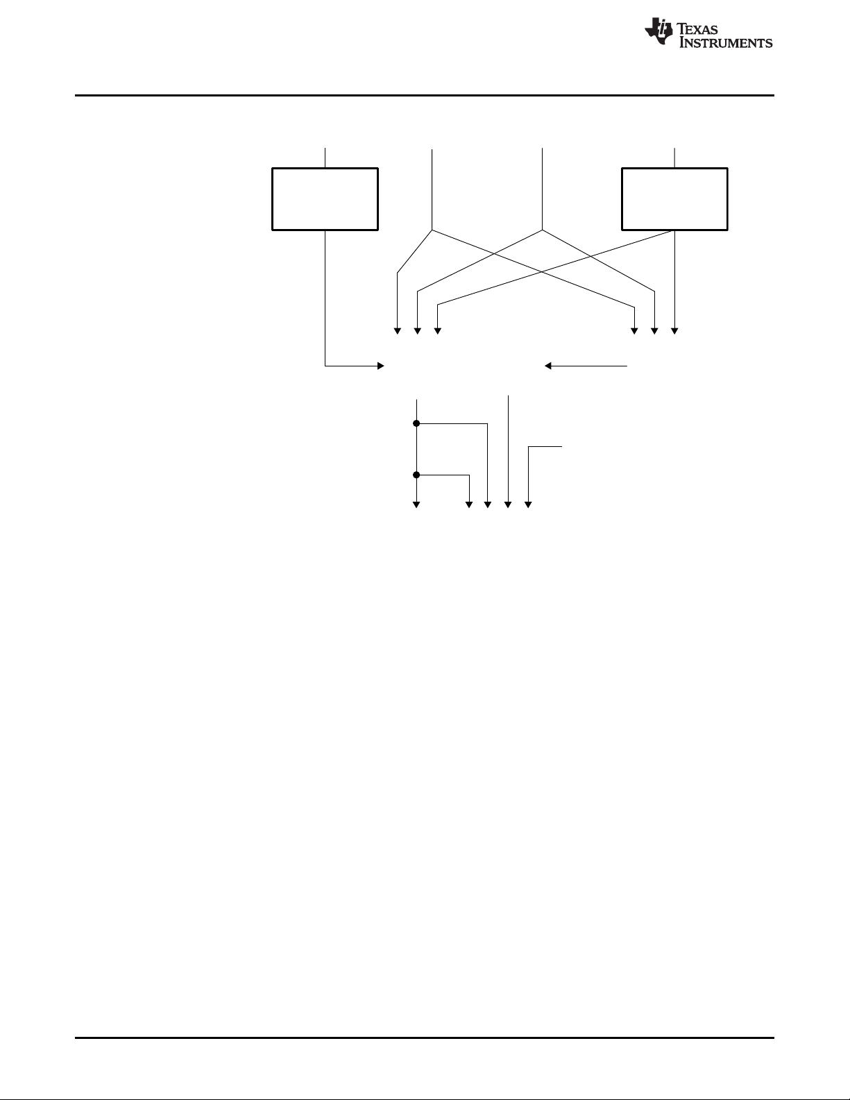
Figure 1-1 shows the operational overview of the bq34210-Q1 fuel gauge.
SLUUBE8–September 2018
Submit Documentation Feedback
Copyright © 2018, Texas Instruments Incorporated
General Description
7
Page 8
Charge
Efficiency
Compensation
Charge
Current
+
Inputs
Remaining
Capacity
(RC)
Discharge
Current
Temperature
Compensation
Self-Discharge
Timer
– –
≤
+
Full
Charge
Capacity
(FCC)
Discharge
Count
Register
(DCR)
Qualified
Transfer
Temperature, Other Data
Main Counters and
Capacity Reference (FCC)
Outputs
Chip-Controlled
Available Charge
LED Display
Two-Wire
Serial Port
– ++
Battery Electronics
Load Estimate
Gas Gauging
www.ti.com
1.1.1 CEDV Gas Gauging Operational Overview
The bq34210-Q1 device accumulates the measured quantities of charge and discharge and estimates
self-discharge of the battery. The bq34210-Q1 device compensates the charge current measurement for
temperature and the state-of-charge of the battery. The device also adjusts the self-discharge estimation
based on temperature. The initial battery state-of-charge estimation on first insertion of the battery pack in
the system may display a factor of the true value; the system must go through a full charge and then a full
discharge cycle before the correct full-charge capacity (FCC) is estimated.
The main charge counter, RemainingCapacity() (RC) register, represents the available capacity or energy
in the battery at any given time. The bq34210-Q1 device adjusts RC for charge, self-discharge, and other
compensation factors. The information in the RC register is accessible through the I2C interface. The
FullChargeCapacity() (FCC) register represents the initial or last measured full discharge of the battery. It
is used as the battery full-charge reference for relative capacity indication. FCC is accessible through the
I2C interface.
1.1.2 Main Fuel Gauge Registers
Remaining Capacity (RC) — Remaining capacity in the battery
Figure 1-1. bq34210-Q1 CEDV Gas Gauging Operational Overview
RC represents the remaining capacity in the battery. The bq34210-Q1 device computes RC in units
of mAh.
RC counts up during charge to a maximum value of FCC and down during discharge and selfdischarge to a minimum of 0. In addition to charge and self-discharge compensation, the bq34210Q1 device calibrates RC at three low-battery-voltage thresholds, EDV2, EDV1, and EDV0. This
provides a voltage-based calibration to the RC counter.
8
Design Capacity (DC) — User-specified battery full capacity
General Description
Copyright © 2018, Texas Instruments Incorporated
SLUUBE8–September 2018
Submit Documentation Feedback
Page 9

www.ti.com
DC is the user-specified battery full capacity. It is calculated from Design Capacity mAh and is
represented in units of mAh. It also represents the full-battery reference for the absolute display
mode.
Full Charge Capacity (FCC) — Last measured discharge capacity of the battery
FCC is the last measured discharge capacity of the battery. It is represented in units of mAh. On
initialization, the bq34210-Q1 device sets FullChargeCapacity() to the data memory value stored in
Full Charge Capacity (FCC). During subsequent discharges, the bq34210-Q1 device updates
FullChargeCapacity() with the last measured discharge capacity of the battery. Once updated, the
bq34210-Q1 device writes the new FullChargeCapacity() value to data memory in mAh to Learned
Full Charge Capacity. FullChargeCapacity() represents the full battery reference for the relative
display mode and relative state-of-charge calculations.
1.1.3 Capacity Learning (FCC Update)
An FCC update occurs if the battery discharges from RC ≥ FCC – Near Full to the EDV2 voltage
threshold with the following conditions:
• No valid charge activity occurs during the discharge period. A valid charge is defined as a charge of
10 mAh into the battery.
• No more than 256 mAh of self-discharge or battery load estimation occurs during the discharge period.
• The temperature does not drop below the low temperature thresholds programmed in Low Temp
during the discharge period.
• The battery voltage reaches the EDV2 threshold during the discharge period and the voltage is greater
than or equal to the EDV2 threshold minus 256 mV when the bq34210-Q1 device detected EDV2.
• Current remains ≥ 3C/32 when EDV2 is reached.
• No overload condition exists when EDV2 threshold is reached or if RC has dropped to
Battery Low % × FCC.
The bq34210-Q1 device sets [VDQ] = 1 in OperationStatus() when a discharge begins. The bq34210-Q1
device sets [VDQ] = 0 if any disqualifying condition occurs. One complication may arise regarding the
state of [VDQ] if [CSYNC] is set in CEDV Gauging Configuration. When [CSYNC] is enabled,
RemainingCapacity() is written to equal FullChargeCapacity() on valid primary charge termination. This
capacity synchronization is done even if the condition RC ≥ FCC – Near Full is not satisfied at charge
termination.
FCC cannot be reduced by more than 256 mAh or increased by more than 512 mAh during any single
update cycle. If [FCC_LIMIT] is set in CEDV Gauging Configuration, then FCC cannot learn above the
Design Capacity mAh. The bq34210-Q1 device saves the new FCC value to the data memory within 4 s
of being updated.
Gas Gauging
1.1.4 End-of-Discharge (EDV) Thresholds and Capacity Correction
The bq34210-Q1 device monitors the battery for three low-voltage thresholds: EDV0, EDV1, and EDV2.
If the [EDV_CMP] bit in CEDV Gauging Configuration is clear, fixed EDV thresholds may be
programmed in Fixed EDV0, Fixed EDV1, and Fixed EDV2 in mV.
If the [EDV_CMP] bit in CEDV Gauging Configuration is set, automatic EDV compensation is enabled
and the bq34210-Q1 device computes the EDV0, EDV1, and EDV2 thresholds based on values stored in
the selected CEDV profile in data memory and the battery's current discharge rate and temperature. If the
[FIXED_EDV0] bit in CEDV Gauging Configuration is also set, then the EDV0 threshold will be set to the
programmed Fixed EDV0, and the EDV1 and EDV2 compensated thresholds will not go below the
programmed Fixed EDV0.
The bq34210-Q1 device disables EDV detection if current exceeds the Overload Current threshold. The
bq34210-Q1 device resumes EDV threshold detection after current drops below the Overload Current
threshold. Any EDV threshold detected is reset after charge is applied and [VDQ] is cleared after 10 mAh
of charge.
The bq34210-Q1 device uses the EDV thresholds to apply voltage-based corrections to the RC register
(see Table 1-1).
SLUUBE8–September 2018
Submit Documentation Feedback
Copyright © 2018, Texas Instruments Incorporated
General Description
9
Page 10

Gas Gauging
Table 1-1. State-of-Charge Based on Low Battery
Voltage
THRESHOLD RELATIVE STATE OF CHARGE
EDV0 0%
EDV1 3%
EDV2 Battery Low %
The bq34210-Q1 device performs EDV-based RC adjustments with current ≥ C/32. No EDVs are set if
current < C/32. The bq34210-Q1 device adjusts RC as it detects each threshold. If the voltage threshold is
reached before the corresponding capacity on discharge, the bq34210-Q1 device reduces RC to the
appropriate amount, as shown in Table 1-1.
If an RC % level is reached on discharge before the voltage reaches the corresponding threshold, then
RC is held at that % level until the threshold is reached. RC is only held if [VDQ] = 1, indicating a valid
learning cycle is in progress. If Battery Low % is set to 0, EDV1 and EDV0 corrections are disabled.
1.1.5 EDV Discharge Rate and Temperature Compensation
If EDV compensation is enabled, the bq34210-Q1 device calculates battery voltage to determine EDV0,
EDV1, and EDV2 thresholds as a function of battery capacity, temperature, and discharge load. The
general equation for EDV0, EDV1, and EDV2 calculation is as follows:
EDV0,1,2 = n (EMF × FBL – |I
• EMF is a no-load cell voltage higher than the highest cell EDV threshold computed. EMF is
programmed in mV in the CEDV profile EMF.
• I
is the current discharge load magnitude.
LOAD
• n = the number of series cells. In the bq34210-Q1 case, n = 1.
• FBL is the factor that adjusts the EDV voltage for battery capacity and temperature to match the noload characteristics of the battery.
FBL = f (C0, C + C1, T) (2)
• C (either 0%, 3%, or Battery Low % for EDV0, EDV1, and EDV2, respectively) and C0 are the
capacity-related EDV adjustment factors. C0 is programmed in the CEDV profile C0. C1 is the desired
residual battery capacity remaining at EDV0 (RC = 0). The C1 factor is stored in the CEDV profile C1.
• T is the current temperature in °K.
• R0 × FTZ represents the resistance of a cell as a function of temperature and capacity.
FTZ = f (R1, T0, C + C1, TC) (3)
• R0 is the first order rate dependency factor stored in the CEDV profile R0.
• T is the current temperature; C is the battery capacity relating to EDV0, EDV1, and EDV2.
• R1 adjusts the variation of impedance with battery capacity. R1 is programmed in the CEDV profile R1.
• T0 adjusts the variation of impedance with battery temperature. T0 is programmed in the CEDV profile
T0.
• TC adjusts the variation of impedance for cold temperatures (T < 23°C). TC is programmed in the
CEDV profile TC.
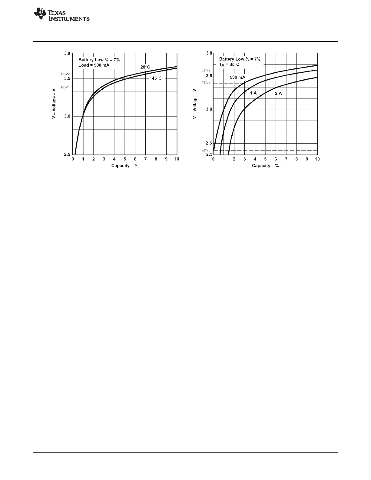
The graphs below show the calculated EDV0, EDV1, and EDV2 thresholds versus capacity using the
typical compensation values for different temperatures and loads for a Li-Ion 18650 cell. The
compensation values vary widely for different cell types and manufacturers and must be matched exactly
to the unique characteristics for optimal performance.
| × R0 × FTZ) (1)
LOAD
www.ti.com
10
General Description
Copyright © 2018, Texas Instruments Incorporated
SLUUBE8–September 2018
Submit Documentation Feedback
Page 11
www.ti.com
Gas Gauging
Figure 1-2. (a) EDV Calculations vs Capacity for Various Temperatures, (b) EDV Calculations vs Capacity
for Various Loads
1.1.6 EDV Age Factor
The EDV Age Factor enables the bq34210-Q1 device to correct the EDV detection algorithm to
compensate for cell aging. This parameter scales cell impedances as the cycle count increases. This new
factor is used to accommodate for much higher impedances observed in larger capacity and/or aged cells.
For most applications, the default value of 0 is sufficient; however, for some very specific applications, this
new aging factor may be required. In those cases, experimental data must be taken at the 0, 100, 200,
and 300 cycle-read points using a typical discharge rate while at ambient temperature. Entering this data
into a TI provided MathCAD™ program will yield the appropriate EDV Age factor value. Contact TI
Applications Support @ http://www-k.ext.ti.com/sc/technical-support/email-tech-support.asp?AAP for more
detailed information.
1.1.7 Self-Discharge
The bq34210-Q1 device estimates the self-discharge of the battery to maintain an accurate measure of
the battery capacity during periods of inactivity. The bq34210-Q1 device makes self-discharge
adjustments to RC every 1/4 second when awake and periodically when in SLEEP mode. The period is
determined by Sleep Current Time.
The nominal self-discharge rate, %PERDAY (% per day), is programmed in an 8-bit value Self-Discharge
Rate by the following relation:
Self-Discharge Rate = %PERDAY/0.0025
1.1.8 Battery Electronic Load Compensation
The bq34210-Q1 device can be configured to compensate for a constant load (as from battery electronics)
present in the battery pack at all times. The bq34210-Q1 device applies the compensation continuously
when the charge or discharge is below the digital filter. The bq34210-Q1 device applies the compensation
in addition to self-discharge. The compensation occurs at a rate determined by the value stored in
Electronics Load. The compensation range is 0 μA–765 μA in steps of approximately 3 µA.
The amount of internal battery electronics load estimate in μA, BEL, is stored as follows:
Electronics Load = BEL/3
SLUUBE8–September 2018
Submit Documentation Feedback
Copyright © 2018, Texas Instruments Incorporated
General Description
11
Page 12
QuitCurrent
(–)QuitCurrent
Current
Time
RelaxationMode ChargeMode DischargeModeRelaxationMode ChargeMode DischargeMode RelaxationMode
ChgRelaxTime
DsgRelaxTime
1 10 1 1 10[DSG]
Gas Gauging
1.1.9 Initial Battery Capacity at Device Reset
The bq34210-Q1 device estimates the initial capacity of a battery pack at device reset, which is the case
when battery cells are first attached to the application circuit. The initial FullChargeCapacity() (FCC) is a
direct copy of the ROM CEDV profile parameter Full Charge Capacity. The initial RC and RSOC are
estimated using the open-circuit voltage (OCV) characteristics of the programmed Li-Ion (LiFePO4 or
NiMH) chemistry, DOD at EDV2, and Design Capacity (maximum chemical capacity). This gives a
reasonably accurate RC and RSOC; however, battery capacity learning is required in order to find the
accurate FCC, RC, and RSOC. During battery capacity learning, learned Full Charge Capacity, and DOD
at EDV2 will be learned and updated.
The determined value of remaining capacity can be further scaled, if needed, through the value of
RemCap Init Percent. Upon a reset, the final value of RemainingCapacity() is initialized from the
RemCap Init Percent value of the initial value correlated to the battery voltage table.
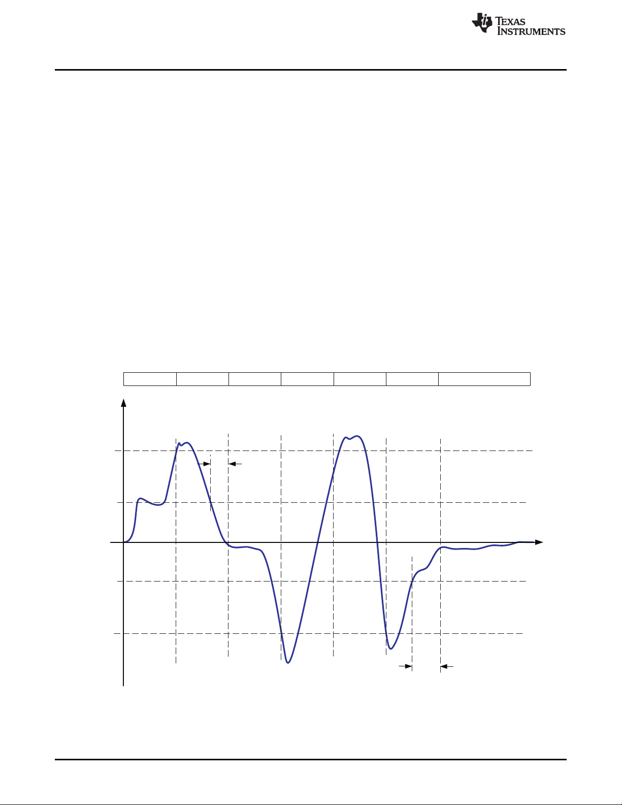
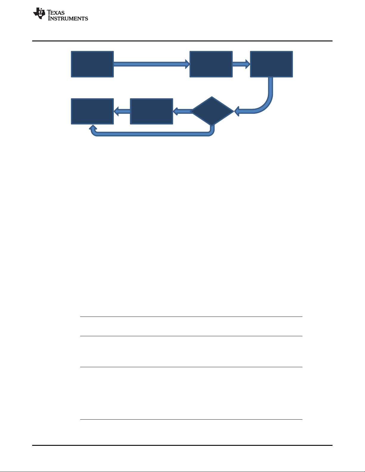
1.1.10 Fuel Gauge Operating Modes
Entry and exit of each mode is controlled by data memory parameters in the Current Thresholds
subclass. The [DSG] flag referenced below is from the MAC GaugingStatus() subcommand and is set in
RELAXATION and DISCHARGE modes. The [DSG] flag in BatteryStatus() is slightly different—it sets only
in DISCHARGE mode and not in RELAXATION mode.
CHARGE mode is exited and RELAXATION mode is entered when Current() goes below Quit Current for
a period of Charge Relax Time. DISCHARGE mode is entered when Current() goes below
(–)Dsg Current Threshold. DISCHARGE mode is exited and RELAXATION mode is entered when
Current() goes above (–)Quit Current threshold for a period of Discharge Relax Time. CHARGE mode is
entered when Current() goes above Chg Current Threshold.
www.ti.com
Figure 1-3. Fuel Gauge Operating Mode Example
12
General Description
Copyright © 2018, Texas Instruments Incorporated
SLUUBE8–September 2018
Submit Documentation Feedback
Page 13

www.ti.com
1.1.11 CEDV Smoothing
The bq34210-Q1 device has the ability to smooth the RemainingCapacity() during discharge in order to
avoid a drop in RelativeStateOfCharge() when the EDV thresholds are reached. This feature is enabled by
setting the Smoothing Config [SMEN] = 1 and configuring the Smoothing Start Voltage and
Smoothing Delta Voltage.
The smoothing will activate only when all of the following conditions are true:
• Current() < 0
• Voltage() < Smoothing Start Voltage
• EDV2 has been reached ([EDV2] = 1) OR (Voltage() – present EDV2 threshold) < Smoothing Delta
Voltage.
• Maximum Voltage() during the previous one minute is less than the maximum Voltage() during the
current minute (that is, "drop rate" is greater than 0).
• RemainingCapacity() is greater than the capacity at the next EDV point.
While smoothing is active, the "drop rate" is used to estimate the time to the EDV point under the
assumption that the rate is constant (linear). This information is then used to estimate how much current
would need to be applied in order to have RemainingCapacity() reach the expected capacity at the EDV
point. The actual Current() is then scaled by the "smoothing current." This will either speed up or slow
down the RemainingCapacity() accumulation to reach the EDV threshold at the correct time.
Whenever the RemainingCapacity() accumulation is actively scaled, the OperationStatus()[SMTH] bit will
be set.
Smoothing deactivates whenever an EDV threshold is reached until the rate to the next EDV threshold
can be calculated; however, smoothing past the EDV2 point only occurs if Smoothing Config [SMEXT] is
set to 1.
To improve smoothing at the end of discharge, the SME0 configuration bit provides additional flexibility.
This is particularly useful when FIXED_EDV0 is set and the calculated EDV2/EDV1 is lower than EDV0. In
this scenario, the State-of-Charge (SOC) smooths to EDV2, then to EDV1, and then to EDV0, leading to
SOC jumps. If the SME0 bit is set, then the SOC smooths directly to EDV0, leading to a smooth transition
to empty.
Table 1-2 shows the available smoothing configurations.
Gas Gauging
Smoothing Config
[SMEN]
0 0 0 No Smoothing
0 0 1 No Smoothing
0 1 0 No Smoothing
0 1 1 No Smoothing
1 0 0 Smoothing to EDV2
1 0 1 Smoothing to EDV0 if calculated EDV2/EDV1 is less than EDV0.
1 1 0 Smoothing to EDV2 ≥ EDV1 ≥ EDV0
1 1 1 Smoothing to EDV0 if calculated EDV2/EDV1 is less than EDV0.
Smoothing Config
The bq34210-Q1 device can also add smoothing during charging. In situations when the FCC is not
updated during a discharge cycle or on a subsequent charge cycle, if the valid charge termination is
reached, RSOC is synced to 100% regardless of the true RSOC. To help in scenarios like these, the
device enables the SMOOTHEOC_EN bit (default is enabled). When enabled, the RSOC value is
gradually increased to 100% instead of a sudden jump if the following are true:
a. Battery is charging.
b. Cell Voltage > Taper Voltage
c. Charge Current is decreasing AND is below the EOC Smooth Current threshold for EOC Smooth
Current Time.
SLUUBE8–September 2018
Submit Documentation Feedback
[SMEXT]
Table 1-2. Smoothing Configurations
CEDV Config
[SME0]
Copyright © 2018, Texas Instruments Incorporated
Description
General Description
13
Page 14

Accumulated Charge Measurement
1.2 Accumulated Charge Measurement
The bq34210-Q1 device integrates an Accumulated Charge function that measures the integrated
charge passed in or out of the cell since the integration is reset. This function can be used to generate an
alert to the host when a programmable threshold of Accumulated Charge is achieved.
The device also integrates the elapsed time since the integration began, assuming the timer was not
interrupted by a power cycle or put into SHUTDOWN mode. This time is read using the command
AccumulatedTime(). If an event has occurred that interrupted the timer, the value of AccumulatedTime()
will be fixed unchanging at 0 until the integration is reset.
The charge and time integration is reset at full charge termination or upon issue of the ACCUM_RESET
command. While the battery is discharging (that is, the measured Current() is negative), then the charge
integration counter increases. If the battery starts charging (that is, the measured Current() is positive),
then the charge integration counter decreases. The integrated charge value in mAh can be read by the
host using the command AccumulatedCharge(). The elapsed time (which does not decrease in value) is
read by issuing the AccumulatedTime() command.
The Accumulated Charge calculation uses the current measured across the sense resistor and, similar to
the coulomb counter integration, ignores currents below a programmed level controlled by CC Deadband.
In periods when the bq34210-Q1 device is in SLEEP mode, the Accumulated Charge integration
includes an estimate of the charge integrated based on analysis of the periodic measured current.
If the user prefers to include cell self-discharge in the integration, this capability can be enabled or
disabled using the [IGNORE_SD_EN] configuration bit.
The charge integration can also be limited to only include positive (charging) currents, only negative
(discharging) currents, or both, through setting the [ACCHG_EN] and [ACDSG_EN] configuration bits. If
both [ACCHG_EN] and [ACDSG_EN] are reset, then the timer is halted. These bits can be set using the
ACCUM_CHG_EN() and ACCUM_DSG_EN() commands.
When the cell is fully charged and the FC bit is set due to normal charge termination, then the integration
counter is again reset. At this point, the values of Accumulated Charge and time just before reset are
stored and can be read using LastAccumulatedCharge() and LastAccumulatedTime(). The values stored
in LastAccumulatedCharge() and LastAccumulatedTime() are cleared each time the command is issued
and the respective value is read. They are also overwritten whenever the integration counter is reset
again. The user can set thresholds to alert the host when AccumulatedCharge() reaches a particular level
in both the charge (positive) and discharge (negative) directions. These thresholds are set by Accum
Charge Positive Threshold and Accum Charge Negative Threshold.
www.ti.com
Due to the charge integration and timer information being stored in RAM, any the device's power cycles or
putting the device into SHUTDOWN will result in the loss of AccumulatedCharge(), AccumulatedTime(),
LastAccumulatedCharge(), and LastAccumulatedTime() data.
AccumulatedCharge() R Signed integer, 2 bytes –32767 32767 0 mAh
LastAccumulatedCharge() R Signed integer, 2 bytes –32767 32767 0 mAh
AccumulatedTime() R Unsigned integer, 2 bytes 0 65535 0 5 min
LastAccumulatedTime() R Unsigned integer, 2 bytes 0 65535 0 5 min
ACCUM_RESET W Boolean NA NA NA
14
General Description
NOTE: AccumulatedCharge() does not reset when a threshold is reached: The reset should be
initiated by the host using ACCUM_RESET. When a threshold is passed, a flag is set in
OperationStatus()[ACTHR].
It is possible for the integration counter to be reset at normal charge termination, but the
charger continues charging the battery for additional time until the charger ceases charging.
In this case, the integration counter would reset, then proceed to integrate this additional
charge. The user should be aware of this possibility and if it is a concern to plan for a
workaround, such as programming the integration to only accumulate discharging currents or
to detect when the charger stops charging, then issue an ACCUM_RESET command to
clear any residual charging integration.
Command R/W Type Min Max Default Units
SLUUBE8–September 2018
Submit Documentation Feedback
Copyright © 2018, Texas Instruments Incorporated
Page 15

www.ti.com
1.3 End-Of-Service Determination
The bq34210-Q1 device incorporates the End-of-Service (EOS) Determination function to determine the
end of useful service of the battery and to provide alerts based on this detection. Learning phases are
used to gather information about the present state of the battery through its cell resistance. Learning
cycles are coordinated by the bq34210-Q1 device with the host, which enables and disables the learning
load. LEN or LLEN is used to denote the Learning Load Enable function. The EOS Determination function
is enabled when [EOS_EN] in ManufacturingStatus() = 1. This bit can be toggled using the EOS_EN()
subcommand. The ManufacturingStatus[EOS_EN] bit should not be written directly during CONFIG
UPDATE mode, but instead should be done via the EOS_EN() subcommand. If the [EOS_EN] bit or other
data memory values related to this function are changed directly in data memory, they will not take effect
until a device reset is issued.
For best results, it is recommended that JEITA-based charging is not enabled when the EOS
Determination feature is used.
There are two ways to initiate a learning phase:
a. To have it automatically controlled by the device (recommended) based on when the internal Auto
Learn Time timer has expired since the last successful learning phase OR
b. To have it triggered by the host by writing a ManufacturerAccessControl() EOS_START_LEARN()
subcommand to the device.
Automatic learning is disabled if Auto Learn Time = 0. There is also a special test mode, which is entered
using the [LTEST] bit and sets several timers to short time durations.
The learning phase can be implemented in two ways, which are controlled by the [LSM] bit:
a. CHARGE-BEFORE-DISCHARGE: The system begins a Learn Charge Phase where it enables
charging to a voltage given by the charging voltage determined by the selected algorithm (JEITA, for
example) incremented by Learn Charge Voltage Delta. This increases charging from the level used
when not in a learning phase.
End-Of-Service Determination
NOTE: The data memory value of Last Charge Voltage Tx - Ty is not increased due to this Learn
Charge Phase.
After this charging is completed through normal charge termination, the device waits for the cell to
relax. It then initiates a Learn Discharge Phase, whereby an intended Learn Discharge Current is
enabled for a length of time given by Learn Discharge Time. When this time has expired, the device
disables the Learn Discharge Current. The bq34210-Q1 device analyzes the response of the battery
to this discharge current to estimate the status of the battery regarding its end of usable service.
If needed, the host continues discharging the battery until Voltage() reaches the appropriate voltage,
as determined by the charging algorithm selected, OR
b. DISCHARGE-BEFORE-CHARGE: The device begins by ensuring it is in a RELAXED state (typically
fully or near-fully charged).
The device begins a Learn Discharge Phase by enabling Learn Discharge Current for a length of
time given by Learn Discharge Time. When this time has expired, the device disables the Learn
Discharge Current.
The device can now be recharged to the appropriate voltage, as determined by the charging algorithm
selected, if needed.
NOTE: The learning discharge current value is set by external components and is not directly
controlled by the bq34210-Q1 device. However, this current is monitored throughout the
Learn Discharge Phase and evaluated to ensure it is close to the intended value.
SLUUBE8–September 2018
Submit Documentation Feedback
Copyright © 2018, Texas Instruments Incorporated
General Description
15
Page 16
End-Of-Service Determination
The CHARGE-BEFORE-DISCHARGE approach described above in (a) is appealing in that the battery
voltage is not discharged below the appropriate charging voltage level by the learning phase. However, it
requires the use of a charger with programmable charging voltage, which may be a limitation in some
systems. For those cases, the DISCHARGE-BEFORE-CHARGE approach in (b) is provided, whereby a
charger with a fixed output voltage can be used with the tradeoff that the battery voltage will be
discharged below this level during the Learn Discharge Phase. However, the amount of this reduction in
battery voltage, and thus capacity, can be controlled and limited to acceptable levels through appropriate
device settings.
The response of the battery to the learning discharge current is analyzed and used to estimate the cell
resistance, Rcell, and this resistance estimate is used in two different methods to evaluate the cell EOS
status:
a. Direct Resistance Decisioning (DRD): This method uses the newly measured value of Rcell and
computes the ratio of Rcell with that of an Initial Rcell captured when the battery was first put into
service. The ratios are compared to thresholds to generate an alert and a warning.
• Alert if (Rcell/Initial Rcell) > DRD Alert Level
• Warning if (Rcell/Initial Rcell) > DRD Warning Level
b. Resistance Slope Decisioning: This method uses the changes with respect to time of Rcell,
comparing this to programmable thresholds to generate an alert and a warning.
Use of Resistance Slope Decisioning (RSD) requires an accurate measurement of the time between
consecutive learning phases for calculation of the slope of Rcell change with respect to time. This will not
be possible if the device is powered off between learning phases; in which case, Direct Resistance
Decisioning (DRD) can still be used. If the device is programmed to use Resistance Slope Decisioning
and a power cycle is detected (or anything that could impact the validity of the time measurement between
learning phases), then the device defaults to only using Direct Resistance Decisioning until the device is
continuously powered long enough to complete multiple learning phases and accurately evaluate the
Rcell change over time.
www.ti.com
1.3.1 Alert Config Registers
The Alert registers are detailed in this section.
Alert_x Config Register Matching Register
Alert_0 Config Battery Status Low Byte
Alert_1 Config Battery Status High Byte
Alert_2 Config EOS Learn Status Low Byte
Alert_3 Config EOS Learn Status High Byte
Alert_4 Config EOS Status
Alert_5 Config EOS Safety Status Active Bits
Alert_6 Config Operation Status 2 bits
1.3.1.1 Alert_0 Config
This register matches the Battery Status register low byte.
Bit 7 Bit 6 Bit 5 Bit 4 Bit 3 Bit 2 Bit 1 Bit 0
SLEEP CHGINH FD FCSETV TCA TDA CHG DSG
Default
0 0 0 0 0 0 0 0
Table 1-3. Alert Config Registers
Table 1-4. Alert_0 Config Register Bit Definitions
0x00
16
General Description
Copyright © 2018, Texas Instruments Incorporated
SLUUBE8–September 2018
Submit Documentation Feedback
Page 17
www.ti.com
End-Of-Service Determination
SLEEP = Enables BatteryStatus()[SLEEP]
0 = Disabled (default)
1 = Enabled
CHGINH = Enables BatteryStatus()[CHGINH]
0 = Disabled (default)
1 = Enabled
FD = Enables BatteryStatus()[FD]
0 = Disabled (default)
1 = Enabled
FCSETV = Enables BatteryStatus()[FCSETV]
0 = Disabled (default)
1 = Enabled
TCA = Enables BatteryStatus()[TD]
0 = Disabled (default)
1 = Enabled
TDA = Enables BatteryStatus()[TDA]
0 = Disabled (default)
1 = Enabled
CHG = Enables BatteryStatus()[CHG]
0 = Disabled (default)
1 = Enabled
DSG = Enables BatteryStatus()[DSG]
0 = Disabled (default)
1 = Enabled
1.3.1.2 Alert_1 Config
This register matches the Battery Status register high byte.
Bit 7 Bit 6 Bit 5 Bit 4 Bit 3 Bit 2 Bit 1 Bit 0
RSVD SOCLOW UTC UTD OTC OTD BATHIGH BATLOW
Default
RSVD = Reserved
SOCLOW = Enables BatteryStatus()[SOCLOW]
UTC = Enables BatteryStatus()[UTC]
UTD = Enables BatteryStatus()[UTD]
OTC = Enables BatteryStatus()[OTC]
OTD = Enables BatteryStatus()[OTD]
Table 1-5. Alert_1 Config Register Bit Definitions
0 0 0 0 0 0 0 0
0x00
0 = Disabled (default)
1 = Enabled
0 = Disabled (default)
1 = Enabled
0 = Disabled (default)
1 = Enabled
0 = Disabled (default)
1 = Enabled
0 = Disabled (default)
1 = Enabled
SLUUBE8–September 2018
Submit Documentation Feedback
Copyright © 2018, Texas Instruments Incorporated
General Description
17
Page 18
End-Of-Service Determination
BATHIGH = Enables BatteryStatus()[BATHIGH]
BATLOW = Enables BatteryStatus()[BATLOW]
1.3.1.3 Alert_2 Config
This register matches the EOS Learn Status register low byte.
Bit 7 Bit 6 Bit 5 Bit 4 Bit 3 Bit 2 Bit 1 Bit 0
LCT0 LFAULT LABRT LCMD LPER LRLX LCHG LDSG
Default
0 0 0 0 0 0 0 0
LCT0 = Enables EOSLearnStatus()[LCT0]
LFAULT = Enables EOSLearnStatus()[LFAULT]
LABRT = Enables EOSLearnStatus()[LABRT]
LCMD = Enables EOSLearnStatus()[LCMD]
LPER = Enables EOSLearnStatus()[LPER]
LRLX = Enables EOSLearnStatus()[LRLX]
LCHG = Enables EOSLearnStatus()[LDSG]
LDSG = Enables EOSLearnStatus()[LDSG]
www.ti.com
0 = Disabled (default)
1 = Enabled
0 = Disabled (default)
1 = Enabled
Table 1-6. Alert_2 Config Register Bit Definitions
0x00
0 = Disabled (default)
1 = Enabled
0 = Disabled (default)
1 = Enabled
0 = Disabled (default)
1 = Enabled
0 = Disabled (default)
1 = Enabled
0 = Disabled (default)
1 = Enabled
0 = Disabled (default)
1 = Enabled
0 = Disabled (default)
1 = Enabled
0 = Disabled (default)
1 = Enabled
1.3.1.4 Alert_3 Config
This register matches the EOS Learn Status register high byte.
18
General Description
Copyright © 2018, Texas Instruments Incorporated
SLUUBE8–September 2018
Submit Documentation Feedback
Page 19
www.ti.com
Table 1-7. Alert_3 Config Register Bit Definitions
Bit 7 Bit 6 Bit 5 Bit 4 Bit 3 Bit 2 Bit 1 Bit 0
LDONE LRES LRSTOR LCTLEDGE LUCD LDPAM LDPAT LDPAI
Default
LCTLEDGE = Enables EOSLearnStatus()[LCTLEDGE]
0 0 0 0 0 0 0 0
LDONE = Enables EOSLearnStatus()[LDONE]
0 = Disabled (default)
1 = Enabled
LRES = Enables EOSLearnStatus()[LRES]
0 = Disabled (default)
1 = Enabled
LRSTOR = Enables EOSLearnStatus()[LRSTOR]
0 = Disabled (default)
1 = Enabled
0 = Disabled (default)
1 = Enabled
LUCD = Enables EOSLearnStatus()[LUCD]
0 = Disabled (default)
1 = Enabled
LDPAM = Enables EOSLearnStatus()[LDPAM]
0 = Disabled (default)
1 = Enabled
LDPAT = Enables EOSLearnStatus()[LDPAT]
0 = Disabled (default)
1 = Enabled
LDPAI = Enables EOSLearnStatus()[LDPAI]
0 = Disabled (default)
1 = Enabled
End-Of-Service Determination
0x00
1.3.1.5 Alert_4 Config
This register matches the EOS Status register.
Bit 7 Bit 6 Bit 5 Bit 4 Bit 3 Bit 2 Bit 1 Bit 0
SRRL SRCL RSVD LTI RSDLI RCELLR IRRCOMP IRCOMP
Default
SLUUBE8–September 2018
Submit Documentation Feedback
0 0 0 0 0 0 0 0
SRRL = Enables EOSStatus()[SRRL]
SRCL = Enables EOSStatus()[SRCL]
RSVD = Reserved
LTI = Enables EOSStatus()[LTI]
Table 1-8. Alert_4 Config Register Bit Definitions
0x00
0 = Disabled (default)
1 = Enabled
0 = Disabled (default)
1 = Enabled
0 = Disabled (default)
Copyright © 2018, Texas Instruments Incorporated
General Description
19
Page 20
End-Of-Service Determination
RSDLI = Enables EOSStatus()[RSDLI]
RCELLR = Enables EOSStatus()[RCELLR]
IRRCOMP = Enables EOSStatus()[IRRCOMP]
IRCOMP = Enables EOSStatus()[IRCOMP]
1.3.1.6 Alert_5 Config
This register matches the EOS Safety Status register active bits. Bits 7:4 in the Alert_5 Config register
match the EOS Safety Status register's high byte, Bits 3:0. Bits 3:0 in the Alert_5 Config register match
the EOS Safety Status register's low byte, Bits 3:0.
Bit 7 Bit 6 Bit 5 Bit 4 Bit 3 Bit 2 Bit 1 Bit 0
RSVD RSDLWARN RSDWARN DRDWARN RSVD
Default
0 0 0 0 0 0 0 0
1 = Enabled
0 = Disabled (default)
1 = Enabled
0 = Disabled (default)
1 = Enabled
0 = Disabled (default)
1 = Enabled
0 = Disabled (default)
1 = Enabled
Table 1-9. Alert_5 Config Register Bit Definitions
0x00
RSDL
ALERT
www.ti.com
RSDALERT DRDALERT
RSVD = Reserved
RSDLWARN = Enables EOSSafetyStatus()[RSDLWARN]
RSDWARN = Enables EOSSafetyStatus()[RSDWARN]
DRDWARN = Enables EOSSafetyStatus()[DRDWARN]
RSVD = Reserved
RSDLALERT = Enables EOSSafetyStatus()[RSDLALERT]
RSDALERT = Enables EOSSafetyStatus()[RSDALERT]
DRDALERT = Enables EOSLearnStatus()[DRDALERT]
1.3.1.7 Alert_6 Config
This register matches two bits from the Operation Status low byte.
0 = Disabled (default)
1 = Enabled
0 = Disabled (default)
1 = Enabled
0 = Disabled (default)
1 = Enabled
0 = Disabled (default)
1 = Enabled
0 = Disabled (default)
1 = Enabled
0 = Disabled (default)
1 = Enabled
20
General Description
Copyright © 2018, Texas Instruments Incorporated
SLUUBE8–September 2018
Submit Documentation Feedback
Page 21
www.ti.com
Table 1-10. Alert_6 Config Register Bit Definitions
Bit 7 Bit 6 Bit 5 Bit 4 Bit 3 Bit 2 Bit 1 Bit 0
RSVD RSVD RSVD RSVD RSVD RSVD ACTHR BLT
Default
0 0 0 0 0 0 0 0
RSVD = Reserved
ACTHR = Enables OperationStatus()[ACTHR]
0 = Disabled (default)
1 = Enabled
BLT = Enables OperationStatus()[BLT]
0 = Disabled (default)
1 = Enabled
1.3.2 Smoothing Config Register
Table 1-11. Smoothing Config Register Bit Definition
Bit 7 Bit 6 Bit 5 Bit 4 Bit 3 Bit 2 Bit 1 Bit 0
RSVD RSVD RSVD RSVD
Default
0 0 0 0 0 0 0 0
0x00
0x00
SMOOTH
EOC_EN
End-Of-Service Determination
SMEXT VAVG SMEN
RSVD = Reserved
SMOOTHEOC_EN = Allows smoothing of RemCap once Current starts decreasing during the end of charge (EOC).
0 = End of charge smoothing is not enabled.
1 = End of charge smoothing is enabled (default).
SMEXT = When set to 1, smoothing continues to EDV1 and EDV0 points. When set to 0, smoothing stops at
VAVG = Enables smoothing to use average voltage
SMEN = Smoothing result is reported on RemainingCapacity().
EDV2. Default is 0.
When set to 1, smoothing uses average voltage. When set to 0 smoothing uses measured voltage.
Default is 0.
When set to 1, the smoothing result is reported on RemainingCapacity(). When set to 0, the normal
CEDV remaining capacity is reported. Default is 0.
1.3.3 End-Of-Service Determination—Detailed Description
The EOS Configuration data memory is used to configure certain settings associated with the EOS
Determination function.
Table 1-12. EOS Configuration
Bit 7 Bit 6 Bit 5 Bit 4 Bit 3 Bit 2 Bit 1 Bit 0
RSVD RSVD RSVD RSVD LTEST LVR LSM RSVD
Legend: RSVD = Reserved. Do not use.
LTEST = Learn Test Mode Control
This bit is used to put the device into a test mode for reduced timing testing of the EOS
Determination function.
When this bit is set = 1, the following values are set:
SLUUBE8–September 2018
Submit Documentation Feedback
Copyright © 2018, Texas Instruments Incorporated
General Description
21
Page 22

Learn
Post-Relax
Phase
Learn
Charge
Phase
Learn
Pre-Relax
Phase
Learn
Discharge
Phase
Voltage
Restore?
yes
no
Voltage
Restore
Phase
Learning
Phase
Complete
End-Of-Service Determination
Auto Learn Time = 10 min
Auto Learn Retry Time = 5 min
Alert-Warn Learn Time = 10 min
Minimum Learn Time = 10 min
0 = The device uses the values programmed in data memory for the above parameters
(default).
LVR = Learn Voltage Restore Control
This bit determines whether the device continues discharging during Learn Discharge Phase
until Voltage() reaches the appropriate Last Charge Voltage Tx - Ty (when set = 1), or to
simply stop discharge when the timer reaches Learn Discharge Time (when set = 0).
1 = The device continues Learn Discharge Phase until Voltage() reaches the appropriate
Last Charge Voltage Tx - Ty.
0 = The device stops Learn Discharge Phase when the timer reaches Learn Discharge
Time (default).
LSM = Learn Sequence Mode Control
This bit determines whether the EOS algorithm uses CHARGE-BEFORE-DISCHARGE or
DISCHARGE-BEFORE-CHARGE mode.
1 = DISCHARGE-BEFORE-CHARGE mode is used.
0 = CHARGE-BEFORE-DISCHARGE mode is used (default).
The device includes a variety of flags to provide visibility into the operation of the EOS Determination
Learning process. These are found in EOSLearnStatus(): 0x64 and 0x65.
The sequence of steps involved in a learning phase differs depending on the setting of [LSM]. These are
depicted in the following figures.
www.ti.com
22
General Description
Figure 1-4. State Diagram for LSM = 0
Copyright © 2018, Texas Instruments Incorporated
SLUUBE8–September 2018
Submit Documentation Feedback
Page 23
Learn
Post-Relax
Phase
Learn
Pre-Relax
Phase
Learn
Discharge
Phase
Voltage
Restore?
yes
no
Learn
Charge
Phase
Learning
Phase
Complete
www.ti.com
Figure 1-5. State Diagram for LSM = 1
1.3.3.1 Periodic and Manual Learn Command
For manual control of learning phases, the ManufacturerAccessControl() subcommand
EOS_START_LEARN() is used. When the device receives this command, it sets the [LCMD] flag and
initiates the learning phase if conditions permit: for example, charger present, no charging or safety faults,
and the temperature is within acceptable limits. The [LDPAT] and [LFAULT] flags will be set if the Learning
Discharge Phase is attempted but temperature conditions do not permit it.
If the device is in periodic (automatic) learning mode, then the [LPER] bit will be set while the device is in
a learning phase.
EOS_ABORT_LEARN(): This ManufacturerAccessControl() subcommand is used to abort a learning
phase that is in progress. Use of this command during a learning phase results in a failed learning phase
and setting the [LABRT] flag, whereupon the device will retry another learning phase after a time period of
Auto Learn Retry Time.
When the device attempts to initiate a learning phase, but conditions do not permit this, then the device
will wait for Auto Learn Retry Time to again attempt a learning phase. Note that this will occur whether
the device is configured in periodic learning or learning is initiated through a host command.
If the case occurs where an alert or warning is detected, either through Direct Resistance Decisioning or
Resistance Slope Decisioning, the Alert-Warn Learn Time is used to schedule a new learning phase. If
multiple fault events must be detected before the alert or warning flags are set, and an stopped learning
phase occurs after the first alert or warning is detected, then Alert-Warn Learn Time is used to schedule
future Rcell measurements rather than Auto Learn Retry Time.
End-Of-Service Determination
NOTE: If [LTEST] is set, special values override the selected timer values to facilitate device
operation testing in a shorter time scale.
To avoid interruption to the EOS Determination measurements and calculations, automatic offset
calibration is not initiated during a learning phase. While it is possible for the host to manually initiate a
calibration event during a learning phase, it is recommended that the host avoid this.
NOTE: Alert-Warn Learn Time has priority over Auto Learn Retry Time, so if multiple
occurrences must be detected before an alert or warning is triggered, and after the first
occurrence is detected that a fault occurred that invalidated a following attempted learning
phase, the Alert-Warn Learn Time will be used to determine the time to the next learning
phase attempt. It should also be noted that if Alert-Warn Learn Time is set to be lower than
Minimum Learn Time, then Minimum Learn Time will be used to determine the time to the
next learning phase attempt.
SLUUBE8–September 2018
Submit Documentation Feedback
Copyright © 2018, Texas Instruments Incorporated
General Description
23
Page 24

End-Of-Service Determination
1.3.3.2 Learn Charge Phase
The operation of the device is first described for the case of [LSM] = 0, in which the device uses
CHARGE-BEFORE-DISCHARGE mode. In this mode, the device first enters Learn Charge Phase by
setting ChargingVoltage() to the appropriate charging voltage determined by the selected charging
algorithm (JEITA, for example) incremented by Learn Charge Voltage Delta. The [LCHG] flag is set and
charge terminates using standard charge termination criteria. Upon termination of charge, then [LCHG] is
cleared. Note that the data memory value of Last Charge Voltage Tx - Ty is not incremented due to this
Learn Charge Phase.
The time while [LCHG] is set is measured and compared against a threshold given by Learn Charge
Time Limit to identify an excessive charging time, which may indicate an issue in the system. When the
learn charging time exceeds this limit, the [LCTO] flag is set, learning is terminated, and the [LFAULT] flag
is set to indicate a fault has occurred. The [LCHG] flag is reset whenever the device exits from
CHARGING mode. If a learning fault occurs, the status flag ([LCHG] in this case) remains set to enable
the host to understand what mode the system was in when the fault occurred.
NOTE: The standard charge termination criteria voltage condition is relative to ChargingVoltage(), so
the same settings are used for Normal and Learn charging phases.
1.3.3.3 Learn Pre-Relax Phase
If [LSM] = 0, then the device next waits for relaxation of the cell, during which Voltage() is monitored for
100-s time windows. While in this phase, the device sets the [LRLX] flag. If the change in the consecutive
100-s averages of Voltage() is less than 4 µV, then relaxation is deemed achieved. If not, the device
continues monitoring for another 100-s time window. It is important that the cell be fully relaxed before the
algorithm can continue onto the Learn Discharge Phase. The status of relaxation can be seen by the
[REST] bit in the Gauging Status register, after which the algorithm can move onto the Learn Discharge
Phase. If a learning fault occurs while in the Learn Pre-Relax Phase or the Learn Post-Relax Phase, the
status flag ([LRLX] in this case) will remain set to enable the host to understand what mode the system
was in when the fault occurred.
When the device is in learning mode (but not in the Learn Discharge Phase), and a current is detected
differently than what is expected, the [LUCD] bit will be set. It is set if the device is attempting to charge or
relax, and a discharge current in excess of Discharge Detection Threshold is detected. It is also set if
the device is in a RELAXATION mode and a charging current in excess of Charge Detection Threshold
is detected. This detection also terminates the learning phase, and this flag will remain set so the host can
recognize why the learning phase was stopped. This bit will be reset to 0 when charging is terminated or
the register is read.
www.ti.com
1.3.3.4 Learn Discharge Phase
After achieving relaxation, the bq34210-Q1 device next enters the Learn Discharge Phase, whereby the
device enables the Learn Discharge Current (depending on the [LENCTL] setting), sets the [LDSG] flag,
and begins the timer.
External circuitry is required to actively discharge the battery at a constant current rate where the
discharge current flows through the sense resistor connected across SRP – SRN. This will be
implemented by the host directly controlling the current. To provide sufficient resolution in the associated
calculations, it is important that the level of this Learn Discharge Current be large enough so that it
generates a cell voltage change of approximately 5 mV or greater. A current level of C/20 or higher is
generally recommended.
[LDSG] remains enabled until the timer reaches Learn Discharge Time, at which point (if [LVR] = 0) the
[LDSG] flag is reset and Learn Discharge Current is disabled. The device then transitions into the Learn
Post-Relax Phase.
The [LVR] (Learn Voltage Restore) bit is used to tell the device to resume discharging using the learning
load after completion of the voltage determined by the charging algorithm selected until Voltage() reaches
the appropriate voltage determined by the charging algorithm selected (when [LVR] is set = 1). When this
is finished (or when the Learn Post-Relax Phase is complete, if [LVR] is set = 0), the entire learning phase
is complete, at which point the device sets the [LDONE] flag.
24
General Description
Copyright © 2018, Texas Instruments Incorporated
SLUUBE8–September 2018
Submit Documentation Feedback
Page 25

www.ti.com
During the time period while the timer is active for the Learn Discharge Time period, the average current
and average temperature over this time period will be calculated by the device and saved at the
conclusion of the Learn Discharge Phase. These values are used in later calculations to provide better
accuracy.
While the device is in Learn Discharge Phase, it is also monitoring Current() and ensuring it is within an
acceptable range around the intended discharge current. The algorithm knows the intended current based
on the Learn Discharge Current, which is the intended Learn Discharge Current implemented using the
external circuitry. This current should generally be designed greater than C/20. The boundary the
algorithm uses for the acceptable range is determined using the Learn Discharge Current Boundary. If
the current exceeds the Learn Discharge Current Boundary, the [LDPAI] and [LFAULT] flags are set,
and the learning phase is stopped. If a learning fault does occur, the status flag ([LDSG] in this case) will
remain set to allow the host to understand what mode the system was in when the fault occurred.
The value of Learn Discharge Current should be selected large enough to accept variations in the
current with temperature and system noise, but low enough to ensure identification of other events, such
as an unintended charging session starting or a system load discharge event beginning. The Learn
Discharge Current should also be chosen well above the Discharge Detection Threshold and Quit
Current to ensure proper operation.
End-Of-Service Determination
NOTE: After setting [LDSG], the device will monitor Current() for up to Learn Request Timeout
seconds and start the timer only when the current has entered the acceptable range around
Learn Discharge Current. This will accommodate delay in the host responding to the
ALERT interrupt to see the [LCTLEDGE] signal and enable the Learn Discharge Current.
If the bq34210-Q1 device does not detect a valid current within a time period of Learn
Request Timeout after setting [LDSG], then the device will set [LFAULT], delay a time given
by Auto Learn Retry Time, and then initiate a new learning phase. The [LDSG] flag will
remain set so the host can read and determine the phase in which the fault occurred. The
Learn Request Timeout timer is similarly used after the [LCTLEDGE] signal asserts when
the host should disable the learning load.
The Learn Discharge Phase can be terminated for other criteria (beyond its intended valid termination by
persisting for the Learn Discharge Time period), including Current() exiting the acceptable range, a
safety fault is detected, or a temperature exceeds the allowed learning temperature limits. If the Learn
Discharge Phase is terminated for any reason other than valid termination, then [LFAULT] is set,
indicating that the learning phase was not completed. [LFAULT] is cleared when the learning process is
initiated again.
The Learn Discharge Phase is only allowed when the temperature is within an allowed range, which is
given by the Learn Min Temperature and Learn Max Temperature. If a Learn Discharge Phase is
attempted when the temperature is outside this allowed range, the [LDPAT] and [LFAULT] flags are set.
If the [LSM] is set = 1, then DISCHARGE-BEFORE-CHARGE mode is used, in which the operation
sequence is described below:
1. Check for relaxation by monitoring Voltage() as described above, and delay until relaxation is
achieved.
2. Enable [LDSG], enable the Learn Discharge Current, and reset the timer to begin Learn Discharge
Phase.
3. When the timer reaches Learn Discharge Time, then disable [LDSG] and Learn Discharge Current.
SLUUBE8–September 2018
Submit Documentation Feedback
Copyright © 2018, Texas Instruments Incorporated
General Description
25
Page 26

End-Of-Service Determination
1.3.3.5 Learn Post-Relax Phase
After the Learn Discharge Phase completes, the bq34210-Q1 device will disable the learning current and
enter the Learn Post-Relax Phase, whereby the device again waits for relaxation of the cell, during which
Voltage() is monitored for 100-s time windows. While in this phase, the device sets the [LRLX] flag. If the
change in the consecutive 100-s averages of Voltage() is less than 4 µV, then relaxation is deemed
achieved. If not, the device continues monitoring for another 100-s time window. It is important that the cell
be fully relaxed before the algorithm can continue. The status of relaxation can be seen by the [REST] bit
in the Gauging Status register. If a learning fault occurs while in the Learn Post-Relax Phase, the status
flag ([LRLX] in this case) remains set to enable the host to understand what mode the system was in
when the fault occurred.
As in the Learn Pre-Relax Phase, if a discharge current in excess of Discharge Detection Threshold or
a charging current in excess of Charge Detection Threshold is detected, then the [LUCD] flag is set.
This detection also terminates the learning phase, and this flag will remain set so the host can recognize
why the learning phase was stopped. This bit will be reset to 0 when charging is terminated or the register
is read.
At the completion of the Learn Post-Relax Phase, if in CHARGE-BEFORE-DISCHARGE mode and
Voltage() > the charging voltage determined by the selected charging algorithm and [LVR] = 1, then the
device will set [LDSG] and enable the Learn Discharge Current until Voltage() ≤ the calculated charging
voltage. At which point, [LDSG] is reset and the Learn Discharge Current is disabled. The [LRSTOR] bit
will be set while the device is continuing discharge to reach the calculated charging voltage.
If in DISCHARGE-BEFORE-CHARGE mode and [LVR] = 0, then the device will set [LDONE] and
complete learning. If [LVR] = 1, then the device will initiate a new charging session to charge the battery
back to the appropriate charging voltage determined by the selected charging algorithm using a similar
sequence as described above. In this case, the device sets the [LCHG] and [LRSTOR] flags to indicate to
the host that charging can begin. If charging does not terminate within Learn Charge Time Limit, then
[LCTO] and [LFAULT] is set. If a learning fault does occur, the status flag ([LCHG] in this case) will remain
set to allow the host to understand what mode the system was in when the fault occurred.
www.ti.com
NOTE: It is possible that a Learn Discharge Phase has completed, and a new Rcell value was
calculated and stored, but during a Voltage Restore phase, a fault could occur. This would
cause [LFAULT] to be set, and the device would retry a new learning phase after Auto
Learn Retry Time.
1.3.3.6 Cell Resistance Calculation
The device uses the values obtained during each learning phase to estimate a value of Rcell for the
battery. Note the actual value of this Rcell estimate is not critical here, rather its change as the battery
ages is what is important. The [LRES] bit indicates when a new Rcell value was acquired and stored by
the device.
The change in value of Rcell must be normalized relative to differences in temperature when they are
captured. Therefore, the bq34210-Q1 device uses resistance temperature parameters in Rcell High &
Low Temperature Coefficients to calculate an expected value of resistance at the Learn Target
Temperature.
The Rcell High & Low Temperature Coefficients are obtained during a preproduction test whereby the
customer initiates Initial Rcell calculations at temperatures of 5°C, 25°C, and 40°C. These Initial Rcell
values are put into a spreadsheet provided by TI, which then calculates the values of Rcell High
Temperature Coefficient and Rcell Low Temperature Coefficient. These values are then loaded into
data memory and used by the device to normalize effective Rcell measurements back to an equivalent
value at the Learn Target Temperature.
26
General Description
Copyright © 2018, Texas Instruments Incorporated
SLUUBE8–September 2018
Submit Documentation Feedback
Page 27

[DRDALERT] is set if
Rcell
Initial Rcell
>
Rcell
Initial Rcell
>
DRD Alert Level
100
(1+ )
DRD Warning Level
100
(1+ )
[DRDWARN] is set if
www.ti.com
NOTE: The Rcell and Initial Rcell values read by the device are normalized to Learn Target
Temperature. During the preproduction testing to capture the Initial Rcell values as
described above, it is important to keep the Rcell High & Low Temperature Coefficients
set = 0, so the Initial Rcell values captured there are not further normalized.
The Initial Rcell values should be written using the MAC Commands.
It is important that the temperature remain stable during the learning phase. If the temperature is detected
to vary more than 10°C during certain portions of the learning phase, the learning phase will be stopped,
and the [LDPAT] and [LFAULT] flags will be set.
Learn Target Temperature should be the typical or nominal temperature for intended cell operation.
1.3.3.7 End-Of-Service Evaluation
1.3.3.7.1 Direct Resistance Decisioning
The device uses the change in Rcell relative to the value of Initial Rcell as one method to estimate EOS.
The ratio of Rcell / Initial Rcell is compared to two thresholds to generate [DRDALERT] and [DRDWARN]
flags by:
End-Of-Service Determination
The EOS alerts and warnings are read using the command EOSSafetyStatus(), which will clears the alert
bits in this register. There is also a ManufacturerAccessControl() subcommand EOS_SAFETY_STATUS(),
which can be read and does not clear the alert bits.
The following data memory values are set to provide levels at which the bq34210-Q1 device will generate
an alert or a warning, based on the DRD algorithm.
In normal situations, the value of Rcell is expected to increase over time. If the value of Rcell is detected
to decrease from the previous measurement, this is unexpected and may indicate an abnormal situation,
such as a cell having been replaced. The bq34210-Q1 device will set the [RCELLR] flag if a reduction in
the value of Rcell of more than 2% is detected.
To offer improved robustness, there is the option to enable a filter to help ensure that the condition was
detected for a number of consecutive learning phases through programming DRD Alert Counts and DRD
Warning Counts.
If the DRD Alert calculation is positive for DRD Alert Counts, then [DRDALERT] is set. If DRD Alert
Counts is set = 0, then this test is disabled.
If the DRD Warning calculation is positive for DRD Warning Counts, then [DRDWARN] is set. If DRD
Warning Counts is set = 0, then this test is disabled.
Additionally, once the first instance of the either a DRD Alert or DRD Warning condition is detected, then
the time between automatic learns can be adjusted and is based on Alert-Warn Learn Time. If Alert-
Warn Learn Time = 0, then the value in Auto Learn Time continues to be used.
After DRD Alert Counts number of alert conditions have occurred and a [DRDALERT] was triggered, then
the timing to the next learning phase returns to Auto Learn Time.
When the [DRDALERT] flag is set, it will be cleared after being read by the host. However, if the
[DRDWARN] flag is set, it is NOT cleared after being read by the host, but can only be cleared by the host
using the ManufacturerAccessControl() subcommand EOS_WARN_CLEAR().
1.3.3.7.2 Resistance Slope Decisioning
SLUUBE8–September 2018
Submit Documentation Feedback
This second method the device uses to evaluate EOS is based on the slope of the change in Rcell versus
time. The preferred approach is to use Direct Resistance Decisioning with Resistance Slope Decisioning,
whereby an even more robust solution is obtained.
General Description
Copyright © 2018, Texas Instruments Incorporated
27
Page 28

[RSDLAlert] is set if
longterm
>
>
RSDL Alert Level
100
(1+
RSDL Warning Level
100
(1+
[RSDLWarn] is set if
R
Rate
RRate
)
)
longterm
R
Rate
RRate
[RSDAlert] is set if
Initial
>
Initial
>
Rate Alert Level
100
1+ (
Rate Warning Level
100
1+ (
[RSDWarn] is set if
R
R
RRate
RRate
RRate
RRate
)
)
End-Of-Service Determination
Resistance Slope Decisioning requires an accurate measurement of the time between consecutive
learning phases, which it uses to calculate the slope of the Rcell change with respect to time. For best
results, this mode should be used with automatic learning mode enabled and the device experiences no
(or few) power cycles during its lifetime.
Here, the device collects Rcell information using periodic learning phases, which may be in either
CHARGE-BEFORE-DISCHARGE or DISCHARGE-BEFORE-CHARGE mode. The device measures
accurately the time between learning phases, and this is then used to calculate the rate of change in Rcell
with respect to time, which is termed RRate. The value of RRate is stored in units of µΩ/day as a two-byte
signed value, which can store values up to a maximum of 32767 µΩ/day. If a value of RRate is calculated
exceeding this level, the value stored will be limited at 32767. If this value is read back by the host, it
should serve as an indication that the RRate value has saturated the range allotted for storing it.
During operation, the algorithm uses the newly measured value of RRate and computes the ratio of RRate
with that of an Initial RRate captured when the battery was first put into service. The ratios are compared
to thresholds to generate an alert and a warning:
The device also maintains a long-term timer value, which counts the time from the completion of the Initial
RRate learning phases to the present time. This value will only be valid if no power cycles or interruptions
to device operation have been encountered since the Initial RRate learning phases were completed. If
there is a power cycle such that the timer was interrupted, then the [RDSLI] flag will be set, which
indicates that no alerts or warnings based on the long-term RSD value (described below) will be triggered.
A long-term value for the resistance slope (given by RRate
from the Initial RRate value to the most recent RRate measurement.
The ratio of RRate to RRate
) is calculated as the change in RRate
longterm
is compared against thresholds to provide further information as:
longterm
www.ti.com
28
NOTE: It is important that the delay between successive Rcell calculations be long enough such
that the slope of resistance change can be accurately calculated. If the triggering of learning
phases is being performed manually (rather than automatically using the Auto Learn Time),
then it is possible for the host to request successive learning phases with too short of a time
delay between them. The minimum time required for successive learning phases is set by
Minimum Learn Time. If the host manually requests a new learning phase without waiting
for Minimum Learn Time, then the [LDPAM] flag will be set and the request for a new
learning phase will be declined. The [LFAULT] flag is not set here because the learning
phase was never started.
The Initial RRate values should be written using the MAC Commands.
It is important that Auto Learn Time be set larger than Minimum Learn Time; otherwise, Minimum
Learn Time will be used in place of Auto Learn Time. It is also recommended that, if Resistance Slope
Decisioning is used, the value of RRate be ~>10 in practice, to enable appropriate resolution during
mathematical computation within the device.
NOTE: Minimum Learn Time also limits the time between successive Rcell measurements even
when DRD Decisioning is used and RSD/RSDL Decisioning is not used. In the case where
RSD/RSDL Decisioning is not being used, the user can set the Minimum Learn Time to 0 if
frequent Rcell measurements are needed.
General Description
Copyright © 2018, Texas Instruments Incorporated
SLUUBE8–September 2018
Submit Documentation Feedback
Page 29

www.ti.com
To offer improved robustness, there is the option to enable a filter to help ensure that the condition was
detected for a number of consecutive learning phases through programming RSD Alert Counts and RSD
Warning Counts.
If the RSD Alert calculation is positive for RSD Alert Counts, then [RSDALERT] is set. Similarly, if the
RSDL Alert calculation is positive for RSD Alert Counts, then [RSDLALERT] is set. If RSD Alert Counts
is set = 0, then these tests will not be enabled.
If the RSD Warning calculation is positive for RSD Warning Counts, then [RSDWARN] is set. Similarly, if
the RSDL Warning calculation is positive for RSD Warning Counts, then [RSDLWARN] is set. If RSD
Warning Counts is set = 0, then these tests will not be enabled.
Additionally, once the first instance of either an RSD Alert, RSDL Alert, RSD Warning, or RSDL Warning
condition is detected, then the time between automatic learns can be adjusted and is based on Alert-
Warn Learn Time. If Alert-Warn Learn Time = 0, then the value in Auto Learn Time continues to be
used.
When the bq34210-Q1 device is operating in Resistance Slope Decisioning mode and a power cycle is
detected, such that the timer is stopped and restarted, then newly calculated values of RRate will no
longer be compared against the long-term value of the resistance slope. Thus, the [RSDLAlert] and
[RSDLWarn] flags will never be set. The [RSDLI] flag is set to indicate an interruption has occurred.
In addition, a new value of RRate cannot be calculated until two learning phases are completed with the
device maintaining power between them, so a valid time is available for the calculation.
If the system designer is concerned about the power drawn by the bq34210-Q1 timer, another option is for
the system to power up the bq34210-Q1 device, maintain power long enough for the device to complete
two learning phases and calculate a valid RRate value for evaluation. The device can then be powered
down until another evaluation is needed, in which case the sequence can be repeated.
End-Of-Service Determination
1.3.3.8 Initial Rcell and RRate Learning Process
When the cell is first put into service, Initial Learn Pulse Number learning phases will be initiated, each
resulting in a calculated Rcell value. These Rcell values will be averaged and stored as Initial Rcell.
The EOS_RCELL_RRATE_LEARN() command is available for the host to initiate the measurement of an
Initial Rcell value. This command will also reset the timer measuring the time since completion of the
Initial Rcell measurement.
NOTE: The Initial Rcell measurement can be done while in test mode, but the Initial RRate
measurement cannot practically be done in test mode with an actual cell, due to the minimal
change expected in the values of Rcell when using the short time durations of the test mode.
If any fault is detected during the Initial Rcell or Initial RRate measurement process, all learned data
associated with the Rcell measurement in progress is discarded, and the device will initiate a new
learning phase after Auto Learn Retry Time. If the Initial RRate value measured by the device is 0 or
negative, this result is ignored, and the device will still consider Initial RRate not yet learned. In this case,
the host should initiate a new Initial RRate using EOS_RCELL_RRATE_LEARN().
The time since the last successful calculation of Rcell is provided via the EOSSTATUS2() command. If
timing were disrupted since the last Rcell calculation, such as caused by a power cycle on the device,
then this register will read 0 until a new Rcell is calculated.
Similarly, the time since the successful calculation of Initial Rcell is also provided via the EOSSTATUS2()
command. If timing was disrupted since the Initial Rcell calculation, this register will read 0, and the
[RSDLI] flag will be set.
When the cell is first put into service, the first learning phases that are initiated are used to calculate
multiple values for RRate. These multiple values are averaged and stored as Initial RRate. For the Initial
RRate procedure to operate, the Auto Learn Time cannot be set = 0.
SLUUBE8–September 2018
Submit Documentation Feedback
Copyright © 2018, Texas Instruments Incorporated
General Description
29
Page 30

End-Of-Service Determination
NOTE: For the EOS Determination function to provide best results, it is important that the values of
Rcell be measured at a consistent level of charge. This means it cannot directly be used
together with JEITA charging without additional steps.
If the Initial Learn Pulse Number is set greater than 1, Learn Voltage Restore is set = 1, and Learn
Sequence Mode is set = 1 (DISCHARGE-BEFORE-CHARGE mode), the bq34210-Q1 device will wait for
the cell to be charged after each Learn Post-Relax Phase is complete before it completes the learning
cycle for a single initial learn pulse. It then initiates the next learning cycle for the next initial learn pulse.
However, if the Learn Voltage Restore is set = 0, then the bq34210-Q1 device will wait for the cell to be
charged back after the Learn Post-Relax Phase is complete, but will immediately complete the learning
cycle and initiate a new learning cycle for the next initial learn pulse. This will result in each of the multiple
initial learn pulses being captured at slightly different depth-of-discharge, which can introduce an
additional error into the measurement, depending on the battery chemistry used. To avoid this error, it is
recommended that either the Learn Voltage Restore be set = 1 or the Initial Learn Pulse Number be
set = 1.
Because the Learn Discharge Pulses only discharge the battery a small amount, recharging to
compensate for this small discharge may create difficulty in achieving proper charge termination,
depending on the battery chemistry used. This case should be evaluated during development, and if
necessary, the pertinent charge termination settings can be adjusted to address this issue. For example,
the Current Taper Window and Minimum Taper Capacity may need to be reduced to facilitate proper
charge termination.
A possible issue can arise if the bq34210-Q1 gauge is configured for CHARGE-BEFORE-DISCHARGE
mode, and a fault occurs after charging, but before the Learn Discharge Phase has completed. Then
when the device attempts a new learning phase, it may have difficulty achieving proper charge
termination, since the battery was already charged to the required level. In this case, a possible
workaround would be to enable the learning load and discharge the battery back to the original level
before the next learning phase occurs.
www.ti.com
30
General Description
Copyright © 2018, Texas Instruments Incorporated
SLUUBE8–September 2018
Submit Documentation Feedback
Page 31

2.1 Device Configuration
The configuration options are configured via the following Smoothing Config and Operation Config A
data memory registers. These registers are programmed and read via the methods described in
Section 5.1, Accessing the Data Memory.
2.1.1 Smoothing Config Register
Table 2-1. Smoothing Config Register Bit Definition
Bit 7 Bit 6 Bit 5 Bit 4 Bit 3 Bit 2 Bit 1 Bit 0
RSVD RSVD RSVD RSVD
Default
0 0 0 0 0 0 0 0
Chapter 2
SLUUBE8–September 2018
Functional Description
SMOOTH
EOC_EN
0x00
SMEXT VAVG SMEN
RSVD = Reserved
SMOOTHEOC_EN = Allows smoothing of RemCap once Current starts decreasing during the end of charge (EOC).
0 = End of charge smoothing is not enabled.
1 = End of charge smoothing is enabled (default).
SMEXT = When set to 1, smoothing continues to EDV1 and EDV0 points. When set to 0, smoothing stops at
VAVG = Enables smoothing to use average voltage
SMEN = Smoothing result is reported on RemainingCapacity().
EDV2. Default is 0.
When set to 1, smoothing uses average voltage. When set to 0 smoothing uses measured voltage.
Default is 0.
When set to 1, the smoothing result is reported on RemainingCapacity(). When set to 0, the normal
CEDV remaining capacity is reported. Default is 0.
2.1.2 Operation Configuration A (Operation Config A) Register
Table 2-2. Operation Config A Register Bit Definitions
Bit 7 Bit 6 Bit 5 Bit 4 Bit 3 Bit 2 Bit 1 Bit 0
High Byte TEMPS Default Seal ALERT_POL ALERT_EN SCALED SLEEP
Low Byte DefaultFA LFOONLY
High Byte
TEMPS = When set to 1, the external thermistor is selected for Temperature() measurements.
Default Seal = Seal during POR
0 = No Seal after POR (default)
1 = Seal after POR
ALERT_POL = Sets the polarity of the ALERT pin
0 = ALERT is active low.
NIMH_CHG
_EN
NI_DT NI_DV WAKE_EN WK_TH1 WK_TH0
SLPWAKE
CHG
JEITA
SLUUBE8–September 2018
Submit Documentation Feedback
Copyright © 2018, Texas Instruments Incorporated
Functional Description
31
Page 32

External Pin Functions
SLPWAKECHG = Accumulate estimated charge on wake from sleep when Current() > Sleep Current, but not enough
Low Byte
NIMH_CHG_EN = When set, the device performs primary charge termination using the NiXX algorithm. See Charging
WAKE_EN, WK_TH1,
1 = ALERT is active high.
ALERT_EN = When set to 1, the ALERT pin is active.
SCALED = Scaled capacity and/or current bit
SLEEP = The fuel gauge can enter SLEEP, if operating conditions allow. True when set.
JEITA = Enables JEITA Temperature functionality. See Charging and Charge Termination.
DefaultFA = Default to FULL ACCESS mode on power up (1 = yes)
LFOONLY = Use LFO only for ADC conversions (1 = yes).
NI_DT = When set, the device performs primary charge termination using the ΔT/Δt algorithm. See Charging
NI_DV = When set, the device performs primary charge termination using the –ΔVt algorithm. See Charging
WK_TH0 =
The mA and mAh settings and reports will take on a value that is artificially scaled. This setting has
no actual effect within the gauge. It is the responsibility of the host to reinterpret the reported values.
Scaled current measurement is achieved by calibrating the current measurement to a value lower
than actual.
to trigger a wake event. Enabled when set.
LFOONLY is a lower power mode, but has a reduction in accuracy.
and Charge Termination.
and Charge Termination.
and Charge Termination.
These bits configure the current wake function. See the bq34210-Q1 Automotive 1-Series Cell
System-Side CEDV Fuel Gauge for Rarely Discharged Batteries Data Sheet (SLUSCG1) for
threshold values.
www.ti.com
2.2 External Pin Functions
2.2.1 Wake-Up Comparator
The wake-up comparator indicates a change in cell current while the fuel gauge is in SLEEP mode. The
Operation Config A [WK_TH1:WK_TH0] bits select the appropriate comparator threshold for the sense
resistor value used. The Operation Config A [WAKE_EN] bit selects one of two possible voltage
threshold ranges for the given sense resistor selection. An internal interrupt is generated when the
threshold is reached in either the charge or discharge direction. Setting the [WK_TH1] and [WK_TH0] bits
to 0 disables this feature.
2.2.2 Autocalibration
The fuel gauge provides an autocalibration feature that measures the voltage offset error across SRP and
SRN as operating conditions change. It subtracts the resulting offset error from the normal sense resistor
voltage, VSR, for maximum measurement accuracy.
Autocalibration of the coulomb counter begins on entry to SLEEP mode, except if Temperature() is ≤ 5°C
or Temperature() ≥ 45°C.
The fuel gauge also performs a single offset when:
• The condition of AverageCurrent() ≤ 100 mA
• {voltage change since last offset calibration ≥ 256 mV} or {temperature change since last offset
calibration is greater than 8°C for ≥ 60 s}.
Capacity and current measurements continue at the last measured rate during the offset calibration when
these measurements cannot be performed. If the battery voltage drops more than 32 mV during the offset
calibration, the load current has likely increased; thus, the offset calibration is stopped. The
CONTROL_STATUS()[CCA] bit is set during coulomb counter autocalibration.
32
Functional Description
Copyright © 2018, Texas Instruments Incorporated
SLUUBE8–September 2018
Submit Documentation Feedback
Page 33

www.ti.com
2.3 Temperature Measurement
The fuel gauge typically measures battery temperature via its TS input to supply battery temperature
status information to the gas gauging algorithm and charger-control sections of the gauge. Alternatively, it
can be configured to use an internal on-chip temperature sensor or receive temperature data from the
host processor. See Temperature(): 0x06 and 0x07 for specific information on configuration options.
Regardless of which temperature configuration is used, the host processor can request the current battery
temperature by reading the Temperature(), and for internal temperature, InternalTemperature().
The external thermistor circuit requires the use of an 10K NTC 103AT-type thermistor.
2.3.1 Overtemperature Indication
2.3.1.1 Overtemperature: Charge (OT Chg)
If during charging, Temperature() reaches the threshold of OT Chg for a period of OT Chg Time, and
Current() > Chg Current Threshold, then the BatteryStatus()[OTC] bit is set. When Temperature() falls to
OT Chg Recovery, the BatteryStatus()[OTC] bit is cleared.
If OT Chg Time = 0, then the feature is completely disabled.
2.3.1.2 Overtemperature: Discharge (OT Dsg)
If during discharging, Temperature() reaches the threshold of OT Dsg for a period of OT Dsg Time, and
Current() ≤ –Dsg Current Threshold, then the BatteryStatus()[OTD] bit is set. When Temperature() falls
to OT Dsg Recovery, the BatteryStatus()[OTD] bit is cleared.
If OT Dsg Time = 0, then the feature is completely disabled.
Temperature Measurement
2.3.2 Undertemperature Indication
2.3.2.1 Undertemperature: Charge (UT Chg)
If during charging, Temperature() reaches the threshold of UT Chg for a period of UT Chg Time, and
Current() > Chg Current Threshold, then the BatteryStatus()[UTC] bit is set. When Temperature() rises
to UT Chg Recovery, the BatteryStatus()[UTC] bit is cleared.
If UT Chg Time = 0, then the feature is completely disabled.
2.3.2.2 Undertemperature: Discharge (UT Dsg)
If during discharging, Temperature() reaches the threshold of UT Dsg for a period of UT Dsg Time, and
Current() ≤ –Dsg Current Threshold, then the BatteryStatus()[UTD] bit is set. When Temperature() rises
to UT Dsg Recovery, the BatteryStatus()[UTD] bit is cleared.
If UT Dsg Time = 0, then the feature is completely disabled.
2.4 Battery Condition Warnings
2.4.1 Battery Low Warning
The bq34210-Q1 device can indicate, and optionally trigger an alert signal, when the battery voltage falls
below a programmable threshold. This feature is disabled if Battery Low Time is set to 0.
NOTE: If Battery Low Time is set to 30 seconds or higher, the device may initiate an automatic
offset calibration during the time window, resulting in the BATLOW signal being delayed
approximately an additional 15–20 seconds beyond the Battery Low Time setting.
SLUUBE8–September 2018
Submit Documentation Feedback
Copyright © 2018, Texas Instruments Incorporated
Functional Description
33
Page 34

Battery Condition Warnings
Status Condition Action
Normal Voltage() > BATLOW: Battery Low Set Threshold BatteryStatus()[BATLOW] = 0
Trip
Recovery Voltage() > BATLOW:Battery Low Clear Threshold BatteryStatus()[BATLOW] = 0
Voltage() ≤ BATLOW: Battery Low Set Threshold
For
BATLOW:Battery Low Time
2.4.2 Battery High Warning
The bq34210-Q1 device can indicate, and optionally trigger an alert signal, when the battery voltage falls
below a programmable threshold. This feature is disabled if Battery High Time is set to 0.
Status Condition Action
Normal Voltage() > BATHIGH: Battery High Set Threshold BatteryStatus()[BATHIGH] = 0
Trip
Recovery Voltage() > BATHIGH:Battery High Clear Threshold BatteryStatus()[BATHIGH] = 0
Voltage() ≤ BATHIGH: Battery High Set Threshold
For
BATHIGH:Battery High Time duration
2.4.3 Battery Low SOC Warning
The bq34210-Q1 device can indicate, and optionally trigger an alert signal, when the battery state-ofcharge (SOC) falls below a programmable threshold. This feature is disabled by setting SOC Low
Threshold and SOC Low Recovery to 0.
www.ti.com
BatteryStatus()[BATLOW]= 1
BatteryStatus()[BATHIGH]= 1
Status Condition Action
Normal RelativeStateOfCharge() > SOC Low Threshold BatteryStatus()[SOCLOW] = 0
Trip RelativeStateOfCharge() ≤ SOC Low Threshold BatteryStatus()[SOCLOW] = 1
Recovery RelativeStateOfCharge() > SOC Low Recovery BatteryStatus()[SOCLOW] = 0
2.4.4 Battery Level Threshold
The battery level threshold (BLT) feature indicates when the SOC of a battery pack has depleted to a
certain value set in a DF register. This feature allows a host to program two capacity-based thresholds
that govern the triggering of the BLT flag and the setting or clearing of the OperationStatus()[BLT] on the
basis of RemainingCapacity(). The interrupt on pins ALERT1 and/or ALERT2 is enabled or disabled via
Alert1_6[BLT] and Alert2_6[BLT], respectively.
• OperationStatus()[BLT] is set when:
– Current > 0 and RemainingCapacity() > BLTChargeSet(). This threshold is initialized at reset from
Init Charge Set.
– Current ≤ 0 and RemainingCapacity() < BLTDischargeSet(). This threshold is initialized at reset
from Init Discharge Set.
• When either the BLTDischargeSet() or BLTChargeSet() command is received, OperationStatus()[BLT]
will clear and the flag will be deasserted. The new threshold is written to either BLTDischargeSet() or
BLTChargeSet().
• At reset, the flag is set to the deasserted state.
Name
BLT Discharge Set R/W R/W R/W Word S2 — 65535 150 mAh
SE US FA
Access
Table 2-3. BLTDischargeSet()
Protocol Type Min Max Default Unit
34
This read/write word command updates the BLT set threshold for DISCHARGE mode for the next BLT flag
assertion, deasserts the present BLT flag, and clears the OperationStatus()[BLT] bit.
Functional Description
Copyright © 2018, Texas Instruments Incorporated
SLUUBE8–September 2018
Submit Documentation Feedback
Page 35

www.ti.com
Table 2-4. BLTChargeSet()
Name
BLT Charge Set R/W R/W R/W Word S2 — 65535 175 mAh
SE US FA
Access
Protocol Type Min Max Default Unit
The read/write word command updates the BLT set threshold for CHARGE mode for the next BLT flag
assertion, deasserts the present BLT flag, and clears the OperationStatus()[BLT] bit.
Table 2-5. Init Discharge Set
Class Subclass Name Format
Settings BLT Init Discharge Set I2 2 0 32767 150 mAh
Description: Initial value for BLTDischargeSet()
Table 2-6. Init Charge Set
Class Subclass Name Format
Settings BLT Init Charge Set I2 2 0 32767 175 mAh
Description: Initial value for BLTChargeSet()
2.5 Charging and Charge Termination Indication
Charging and Charge Termination Indication
Size in
Bytes
Size in
Bytes
Min Value Max Value
Min Value Max Value
Default
Value
Default
Value
Unit
Unit
2.5.1 Detecting Charge Termination
For proper fuel gauge operation, the cell Charging Voltage must be specified by the user.
The fuel gauge detects charge termination when:
• During two consecutive periods of 40 seconds, the AverageCurrent() < Taper Current.
• During the same two periods, the accumulated change in capacity must be > 0.25 mAh.
• Voltage() > Charging Voltage – Taper Voltage.
When this occurs, the BatteryStatus()[FC] and [TCA] bits are set depending on the SOC Flag Config A
[FCSETVCT] and [TCSETVCT] options. Also, if the CEDV Configuration [CSYNC] bit is set, then
RemainingCapacity() is set equal to FullChargeCapacity().
2.5.2 Charge Inhibit
The fuel gauge can indicate when battery temperature has fallen below or risen above predefined
thresholds Charge Inhibit Temp Low or Charge Inhibit Temp High, respectively. In this mode, the
BatteryStatus()[CHGINH] bit is set to indicate this condition. The [CHGINH] bit is cleared once the battery
temperature returns to the range [Charge Inhibit Temp Low + Temp Hys, Charge Inhibit Temp High –
Temp Hys].
The charging should not start when the temperature is below the Charge Inhibit Temp Low or above the
Charge Inhibit Temp High. The charging can continue if the charging starts inside the window [Charge
Inhibit Temp Low, Charge Inhibit Temp High].
2.6 Power Modes
The fuel gauge has different power modes: NORMAL, SLEEP, CONFIG UPDATE, and SHUTDOWN.
NOTE: Prior to NORMAL mode is INITIALIZATION mode, which is the mode immediately following
battery attachment. This is when the ROM parameters are moved to volatile memory.
• In NORMAL mode, the fuel gauge is fully powered and can run any allowable task.
SLUUBE8–September 2018
Submit Documentation Feedback
Copyright © 2018, Texas Instruments Incorporated
Functional Description
35
Page 36
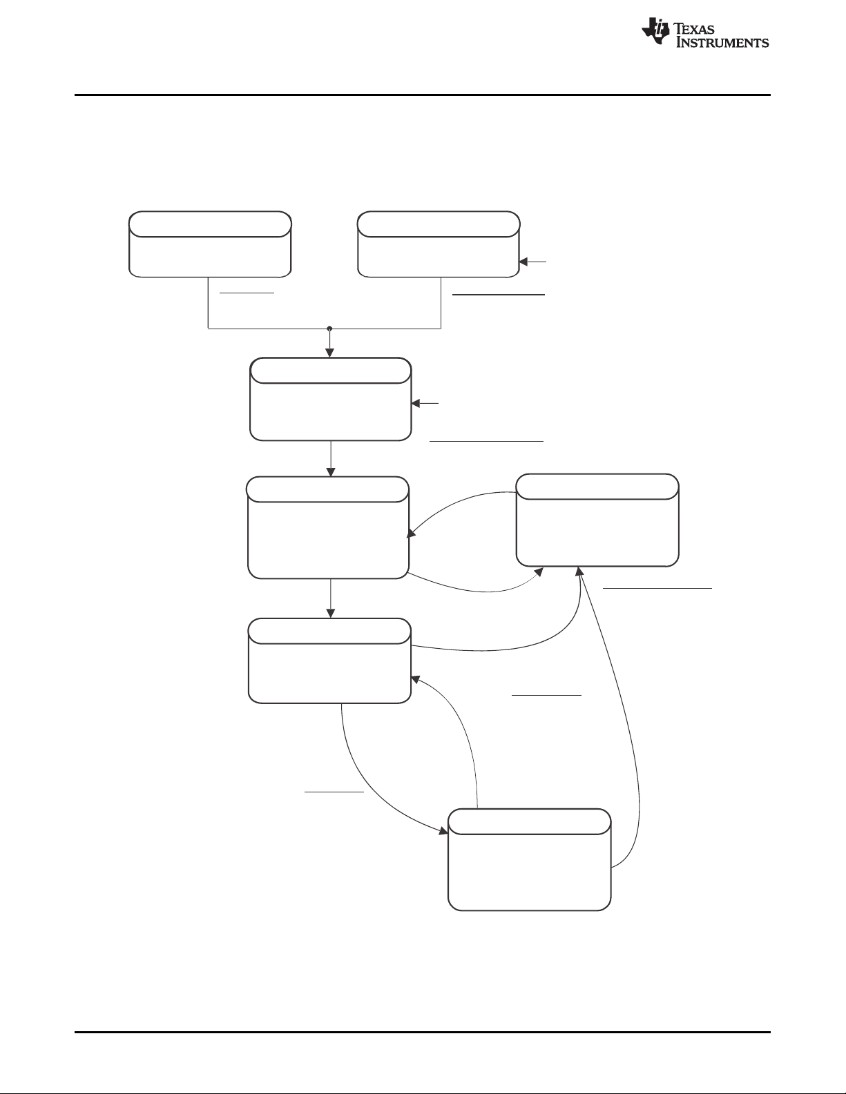
Voltage( ) > S l
eepVoltage
Fuel gauging and data
updatedevery 1 s
NORMAL
ICC= Sleep
SLEEP
Initialize algorithm and data
(No gauging in this mode)
ICC= Normal
INITIALIZATION
Copy configuration ROM
default to RAM data
Power on Reset [POR]
REGIN pin > V
REGIN
min,
SHUTDOWN
REGIN pin = OFF
OFF
Entry to POR
REGIN pin > V
REGIN
min
Via subcommandRESET
(from any mode)
Exit from SHUTDOWN
Exit from CONFIG UPDATE
CONFIG UPDATE
Entry to SLEEP
Entry to CONFIG UPDATE
Exit from SLEEP
Host sends the
and then the commands
(from any mode).
SHUTDOWN_ENABLE
SHUTDOWN
ICC= Normal
Operation Config A [SLEEP] = 1
Sleep Current
AND
<| AverageCurrent() |
Fuel gauging and
data update every
20 seconds
OR
>
OR
Current is detected above +/–30 mA.
Host sets Operation Config A [SLEEP] = 0
Sleep Current| AverageCurrent() |
The ALERT pin is raised high for t
Control()[EXIT_CFG_UPDATE]
Via 240-s
timeout
Host can change RAM.
No gauging in this mode
Control ()[ENTER_CFG_UPDATE]
ALERT
.
Power Modes
• In SLEEP mode, the fuel gauge turns off the high-frequency oscillator (when in RELAXATION mode)
and is in a reduced-power state, periodically taking measurements and performing calculations.
• In CONFIG UPDATE mode, the internal configuration data in the fuel gauge can be modified.
• SHUTDOWN mode is the lowest power mode and requires a power cycle or signal on the ALERT pin.
Figure 2-1 shows the relationship between these modes.
www.ti.com
36
Functional Description
Figure 2-1. Power Mode Diagram for System Shutdown
Copyright © 2018, Texas Instruments Incorporated
SLUUBE8–September 2018
Submit Documentation Feedback
Page 37

www.ti.com
2.6.1 NORMAL Mode
The fuel gauge is in NORMAL mode when not in any other power mode. During this mode, Current(),
Voltage(), and Temperature() measurements are taken, and the interface data set is updated. Decisions to
change states are also made. This mode is exited by activating a different power mode.
Because the gauge consumes the most power in the NORMAL mode, the CEDV algorithm minimizes the
time the fuel gauge remains in this mode.
2.6.2 SLEEP Mode
SLEEP mode is entered automatically if the feature is enabled (Operation Config A [SLEEP] bit = 1) and
Current() is below the programmable level Sleep Current. Once entry into SLEEP mode is qualified, but
prior to entering it, the fuel gauge performs a coulomb counter autocalibration to minimize offset.
During SLEEP mode, the fuel gauge periodically takes data measurements and updates its data set.
However, a majority of its time is spent in an idle condition.
The fuel gauge exits the SLEEP mode if any entry condition is broken, specifically when either:
• Current() rises above Sleep Current.
• A current in excess of I
2.6.3 SHUTDOWN Mode
In SHUTDOWN mode, REG18 is disabled so internal power and all RAM-based volatile data is lost. The
host can command the gauge to immediately enter SHUTDOWN mode by first unsealing the gauge then
enabling the mode with a SHUTDOWN_ENABLE subcommand (0x001B), followed by the SHUTDOWN
subcommand (0x001C). To exit SHUTDOWN mode, the ALERT pin must be raised from logic low to logic
high for t
Both SHUTDOWN_ENABLE and SHUTDOWN are only available while unsealed. Sending
SHUTDOWN_ENABLE will set SHUTDOWN_EN in CONTROL_STATUS(). Sending SHUTDOWN while
SHUTDOWN_EN is set will cause the device to immediately shut down. Sealing the gauge will clear
SHUTDOWN_EN.
Once in SHUTDOWN mode, there are two methods to exit. A power cycle (battery removal and insertion)
is one method. The second method uses the ALERT pin alternative function. Pulling the ALERT pin high
(the time is specified in the data sheet) enables the bq34210-Q1 to exit SHUTDOWN mode and reenter
NORMAL mode.
ALERT
.
WAKE
through R
SENSE
Power Modes
is detected.
2.7 CONFIG UPDATE Mode
If the application requires different configuration data for the fuel gauge, the system processor can update
RAM-based data memory parameters using the Control() ENTER_CFG_UPDATE subcommand to enter
the CONFIG UPDATE mode. Operation in this mode is indicated by the OperationStatus() [CFGUPDATE]
status bit. In this mode, fuel gauging is suspended while the host uses the data commands to modify the
configuration data blocks. To resume fuel gauging, the host sends a Control() EXIT_CFG_UPDATE, or
EXIT_CFG_UPDATE_REINIT subcommand to exit the CONFIG UPDATE mode, which clears
OperationStatus() [CFGUPDATE]. After a timeout of approximately 240 seconds (4 minutes), the gauge
automatically exits the CONFIG UPDATE mode if it has not received an EXIT_CFG_UPDATE or
EXIT_CFGPUPDATE_REINIT subcommand from the host.
2.8 Application-Specific Information
2.8.1 Battery Profile Storage and Selection
The fuel gauge supports two predefined CEDV profiles in device ROM that customers can use by sending
the SET_PROFILE_1 or SET_PROFILE_2 command.
In situations where the user wants to input a custom CEDV profile, they must use the system controller to
set the defaults during system initialization.
To send these commands, the gauge must be in CONFIG UPDATE mode.
SLUUBE8–September 2018
Submit Documentation Feedback
Copyright © 2018, Texas Instruments Incorporated
Functional Description
37
Page 38

Application-Specific Information
2.8.2 First OCV Measurement
Upon power-up, an open-circuit voltage (OCV) measurement of the battery is made via the BAT pin. For
the best gauging results, the system load during the OCV measurement should not exceed a C/20
discharge rate of the battery.
Upon completion of the OCV voltage measurement, BatteryStatus()[OCVCOMP] is set.
2.9 Additional Data Memory Parameter Descriptions
2.9.1 Calibration
The calibration method requires a correction due to offset errors, using a number of samples to get a
statistical average for the golden image. The parameters of particular interest are listed in the following
sections.
NOTE: Calibrate the gauge only when it is in FULL ACCESS UNSEALED mode.
2.9.1.1 CC Gain
CC Gain sets the mA current scale factor for the coulomb counter. Use calibration routines to set this
value.
2.9.1.2 CC Delta
CC Delta sets the mAh capacity scale factor for the coulomb counter. Use calibration routines to set this
value.
www.ti.com
2.9.2 Coulomb Counter Offset (CC Offset)
This register value stores the coulomb counter offset compensation. It is set by automatic calibration of the
device.
2.9.3 Board Offset
This register value stores the compensation for the PCB dependent coulomb counter offset. It is
recommended to use characterization data of the actual PCB to set this value.
2.9.4 Int Temp Offset
This register value stores the internal temperature sensor offset compensation. Use calibration routines to
set this value.
2.9.5 Ext Temp Offset
This register value stores the external temperature sensor offset compensation. Use calibration routines to
set this value.
2.9.6 Pack VOffset
This register value stores the Pack voltage offset measured at the Pack pin. Use calibration routines to set
this value.
2.9.7 Internal Temp Model
Internal Model Coefficient 1 through 4 characterize the internal thermistor of the device. Do not modify
these values without consulting TI.
38
Functional Description
Copyright © 2018, Texas Instruments Incorporated
SLUUBE8–September 2018
Submit Documentation Feedback
Page 39

www.ti.com
2.9.8 Ext a Coef and Ext b Coef
External Model Coefficient 1-5 and Ext Model Coefficient b 1-4 are the thermistor temperature
linearization polynomial coefficients. The default values were computed with a Semitec 103AT thermistor.
If a different type of thermistor is used, then the coefficients will need to be changed. Contact TI to
generate coefficients for a different thermistor.
2.9.9 RC0
RC0 is the ideal value for the internal pullup resistor on the TS pin, shown in counts from the ADC based
on typical reference voltage. No modifications to this value are required
2.9.10 Filter
Defines the filter constant used in ± AverageCurrent() calculation:
AverageCurrent() = a × AverageCurrent() old + (1-a) × Current() with:
a = Filter/256; time constant = 1 s/in(1/a) (default = 14.5 s)
2.9.11 Deadband
Any current within ± Deadband is reported as 0 mA by the Current() function.
2.9.12 CC Deadband
This constant defines the deadband voltage for the measured voltage between the SRP and SRN pins
used for capacity accumulation in units of 294 nV. Any voltages within ±CC Deadband do not contribute
to capacity accumulation.
Additional Data Memory Parameter Descriptions
2.9.13 SOC Flag Configuration A (SOC Flag Config A) Register
The settings in SOC Flag Config A configure how the [TC], [FC], and [TD] flags in GaugingStatus() set
and clear. These flags are also used to set the [TCA], [TDA], and [FC] flags in BatteryStatus().
Table 2-7. SOC Configuration Flag A Register Bit Definitions
Bit 7 Bit 6 Bit 5 Bit 4 Bit 3 Bit 2 Bit 1 Bit 0
High Byte RSVD RSVD RSVD RSVD TCSETVCT FCSETVCT RSVD RSVD
Default
Low Byte
Default
TCSETVCT = Enables BatteryStatus()[TCA] flag set on primary charge termination
FCSETVCT = Enables BatteryStatus()[FC] flag set on primary charge termination
TCCLEARRSOC = Enables BatteryStatus()[TCA] flag clear when RelativeStateOfCharge() ≤ TC:Clear % RSOC Threshold
TCSETRSOC = Enables BatteryStatus()[TCA] flag set when RelativeStateOfCharge() ≥ TC:Set % RSOC Threshold
0 0 0 0 1 1 0 0
0x0C
TCCLEARR
SOC
1 0 0 0 1 1 0 0
RSVD = Reserved
TCSETR
SOC
0 = Disabled
1 = Enabled (default)
0 = Disabled
1 = Enabled (default)
0 = Disabled
1 = Enabled (default)
0 = Disabled (default)
TCCLEARV TCSETV
TDCLEARR
SOC
0x8C
TDSETR
SOC
TDCLEARV TDSETV
SLUUBE8–September 2018
Submit Documentation Feedback
Copyright © 2018, Texas Instruments Incorporated
Functional Description
39
Page 40

Additional Data Memory Parameter Descriptions
1 = Enabled
TCCLEARV = Enables BatteryStatus()[TCA] flag clear when Voltage() ≤ TC:Clear Voltage Threshold
0 = Disabled (default)
1 = Enabled
TCSETV = Enables BatteryStatus()[TCA] flag set when Voltage() ≥ TC:Set Voltage Threshold
0 = Disabled (default)
1 = Enabled
TDCLEARRSOC = Enables BatteryStatus()[TDA] flag clear when RelativeStateOfCharge() ≥ TD:Clear % RSOC Threshold
0 = Disabled
1 = Enabled (default)
TDSETRSOC = Enables BatteryStatus()[TDA] flag set when RelativeStateOfCharge() ≤ TD:Set % RSOC Threshold
0 = Disabled
1 = Enabled (default)
TDCLEARV = Enables BatteryStatus()[TDA] flag clear when Voltage() ≥ TD:Clear Voltage Threshold
0 = Disabled (default)
1 = Enabled
TDSETV = Enables BatteryStatus()[TDA] flag set when Voltage() ≤ TD:Set Voltage Threshold
0 = Disabled (default)
1 = Enabled
2.9.14 SOC Flag Configuration B (SOC Flag Config B) Register
www.ti.com
Table 2-8. SOC Configuration Flag B Register Bit Definitions
Bit 7 Bit 6 Bit 5 Bit 4 Bit 3 Bit 2 Bit 1 Bit 0
FCCCLEAR
RSOC
Default
FCCLEARRSOC = Enables BatteryStatus()[FC] flag clear when RelativeStateOfCharge() ≤ FC:Clear % RSOC Threshold
FCSETRSOC = Enables BatteryStatus()[FC] flag set when RelativeStateOfCharge() ≥ FC:Set % RSOC Threshold
FCCLEARV = Enables BatteryStatus()[FC] flag clear when Voltage() ≤ FC:Clear Voltage Threshold
FDCLEARRSOC = Enables BatteryStatus()[FD] flag clear when RelativeStateOfCharge() ≥ FD:Clear % RSOC Threshold
FDSETRSOC = Enables BatteryStatus()[FD] flag set when RelativeStateOfCharge() ≤ FD:Set % RSOC Threshold
FDCLEARV = Enables BatteryStatus()[FD] flag clear when Voltage() ≥ FD:Clear Voltage Threshold
1 0 0 0 1 1 0 0
FCSETV = Enables BatteryStatus()[FC] flag set when Voltage() ≥ FC:Set Voltage Threshold
FCSET
RSOC
0 = Disabled
1 = Enabled (default)
0 = Disabled (default)
1 = Enabled
0 = Disabled (default)
1 = Enabled
0 = Disabled (default)
1 = Enabled
0 = Disabled
1 = Enabled (default)
0 = Disabled
1 = Enabled (default)
0 = Disabled (default)
1 = Enabled
FCCLEARV FCSETV
0x8C
FDCLEAR
RSOC
FDSET
RSOC
FDCLEARV FDSETV
40
Functional Description
SLUUBE8–September 2018
Submit Documentation Feedback
Copyright © 2018, Texas Instruments Incorporated
Page 41

www.ti.com
FDSETV = Enables BatteryStatus()[FD] flag set when Voltage() ≤ FD:Set Voltage Threshold
0 = Disabled (default)
1 = Enabled
Additional Data Memory Parameter Descriptions
2.9.15 CEDV Gauging Configuration (CEDV Config) Register
Table 2-9. CEDV Gauging Configuration Register Bit Definitions
Bit 7 Bit 6 Bit 5 Bit 4 Bit 3 Bit 2 Bit 1 Bit 0
High Byte RSVD RSVD RSVD SME0 RSVD
Default 0 0 0 0 0 0 0 0
Low Byte RSVD RSVD
Default 0 0 0 0 0 0 0 0
RSVD = Reserved
SME0 = Smoothing towards EDV0 enable. Used with SMEN and SMEXT.
0 = Default
1 = Disabled
RSVD = Reserved
FC_FOR_VDQ =
0 = FC is not required to get VDQ.
1 = FC is required to get VDQ.
RSVD = Reserved
FCC_LIMIT = Learned FCC is not allowed to be higher than DesignCapacity(). Enabled when set.
RSVD = Reserved
FIXED_EDV0 = This bit is used when [EDV_CMP] = 1 to determine if EDV0 will use a fixed threshold.
When set to 1, FIXED_EDV0 will be used.
When set to 0, dynamic EDV0 will be used (default).
SC = This is a selection for learning cycle optimization for a smart charger or independent charger.
0 = Learning Cycle optimized for Smart Charger (default)
1 = Learning Cycle optimized for Independent Charger
EVD_CMP = Method to calculate EDV compensation
0 = Use fixed EDV values.
1 = Use the EDV compensation to calculate the EDV values.
RSVD = Reserved
CSYNC = Sync RemainingCapacity() with FullChargeCapacity() at valid charge termination
0 = NOT Synchronized (default)
1 = Synchronized
CCT = Cycle Count Threshold
0 = Use CC % of DesignCapacity() (default).
1 = Use CC % of FullChargeCapacity().
FIXED_
EDV0
SC EDV_CMP RSVD CSYNC CCT
FC_FOR
_VDQ
RSVD FCC_LIMIT
2.9.16 EMF
This value is the no-load cell voltage higher than the highest cell EDV threshold computed.
2.9.17 C0
This value is the no-load, capacity-related EDV adjustment factor.
SLUUBE8–September 2018
Submit Documentation Feedback
Copyright © 2018, Texas Instruments Incorporated
Functional Description
41
Page 42

Additional Data Memory Parameter Descriptions
2.9.18 R0
This value is the first order rate dependency factor, accounting for battery impedance adjustment.
2.9.19 T0
This value adjusts the variation of impedance with battery temperature.
2.9.20 R1
This value adjusts the variation of impedance with battery capacity.
2.9.21 TC
This value adjusts the variation of impedance for cold temperatures (T < 23°C).
2.9.22 C1
This value is the desired reserved battery capacity remaining at EDV0.
2.9.23 Age Factor
This value enables the bq34210-Q1 device to correct the EDV detection algorithm to compensate for cell
aging.
2.9.24 Fixed EDV0
This value is the EDV0 threshold if [CEDV] is clear in CEDV Config.
www.ti.com
2.9.25 Fixed EDV1
This value is the EDV1 threshold if [CEDV] is clear in CEDV Config.
2.9.26 Fixed EDV2
This value is the EDV2 threshold if [CEDV] is clear in CEDV Config.
2.9.27 Battery Low %
Battery Low % sets the EDV2 level—the highest of the EDV voltages.
2.9.28 Learning Low Temp
This value specifies the minimum temperature above which a discharge must maintain to qualify for
capacity learning.
2.9.29 Overload Current
This value sets the upper current range for EDV detection beyond which EDV detection is halted.
2.9.30 Self Discharge Rate
This value is the estimated self-discharge rate of battery.
2.9.31 Electronics Load
This value should be set to a discharge rate determined by the battery electronics current consumption.
2.9.32 Near Full
This value sets the start of discharge condition for qualified capacity learning.
42
Functional Description
Copyright © 2018, Texas Instruments Incorporated
SLUUBE8–September 2018
Submit Documentation Feedback
Page 43

www.ti.com
2.9.33 Reserve Capacity
This value determines how much actual remaining capacity exists when the fuel gauge reports 0 for
RemainingCapacity() before reaching EDV0. This accommodates a controlled shutdown based on battery
capacity rather than a specific voltage.
NOTE: If the Reserve Capacity is non-zero, then it should be added to the desired Near Full
capacity as well.
2.9.34 Charge Efficiency (Chg Eff)
This is a value to compensate for efficiency loss during charging when estimating total capacity value.
This is based on every coulomb counting charge period and adjusted to reflect the total charge efficiency
of the battery pack.
2.9.35 Discharge Efficiency (Dsg Eff)
This is a value to compensate for efficiency loss during discharging when estimating total capacity value.
This is based on every coulomb counting discharge period and adjusted to reflect the total discharge
efficiency of the battery pack.
2.9.36 Depth of Discharge (DOD) at EDV2
This value is updated by the CEDV gauging algorithm when battery voltage reaches EDV2. If Battery
Low % is altered, the DOD at EDV2 value should be set to (1 – Battery_Low%) × 16384, where
Battery_Low% = Battery Low % ÷ 100. The firmware default value is 15232, which corresponds to a
Battery Low % = 703 (.01 %).
Additional Data Memory Parameter Descriptions
2.9.37 Design Capacity
The DesignCapacity() function reports Design Capacity mAh.
NOTE: There is only a single Design Capacity value for all battery profiles. When setting the
battery profile in production, it may be necessary to update Design Capacity as well for
accurate StateOfHealth() results.
2.9.38 Design Voltage
The default value of DesignVoltage() is stored in Design Voltage and copied upon bq34210-Q1
initialization.
2.9.39 Cycle Count %
If the [CCT] bit is set, the cycle count function counts the accumulated discharge of (FullChargeCapacity()
× CC %) as one cycle. If (FullChargeCapacity() × CC %) is smaller than CC Threshold, CC Threshold is
used for counting.
2.9.40 Charge Inhibit Temp Low
The bq34210-Q1 device does not allow the battery pack to charge if Temperature() is below
Charge Inhibit Temp Low. The [CHGINH] bit is set in BatteryStatus(). The default value is 0°C. Charging
is allowed once the temperature is above Charge Inhibit Temp Low plus Temp Hys value. The
[CHGINH] bit is reset in the BatteryStatus() register.
SLUUBE8–September 2018
Submit Documentation Feedback
Copyright © 2018, Texas Instruments Incorporated
Functional Description
43
Page 44

Additional Data Memory Parameter Descriptions
2.9.41 Charge Inhibit Temp High
The bq34210-Q1 device does not allow the battery pack to charge if Temperature() is above
Charge Inhibit Temp High. The [CHGINH] bit is set in the BatteryStatus(). The default value is 45°C.
Charging is allowed once the temperature is below Charge Inhibit Temp High plus Temp Hys value. The
[CHGINH] bit is reset in the BatteryStatus() register.
2.9.42 Temp Hys
The bq34210-Q1 device has a temperature hysteresis for both Charge Inhibit Temp High and
Charge Inhibit Temp Low conditions to prevent continuous charger ON/OFF behavior. The default value
is 5°C. Charging is allowed once the temperature is below Charge Inhibit Temp High plus Temp Hys or
above Charge Inhibit Temp Low plus Temp Hys value.
2.9.43 Charging and Charge Termination
The bq34210-Q1 does not directly control charging and charge termination, but its registers and
commands create an interface to work with the charging system. For proper bq34210-Q1 operation, the
battery cell charging voltage should be specified by the user in the 3 Charge Voltage T#-T# registers.
These parameters should be set to the recommended charging voltage battery.
The bq34210-Q1 device includes multiple algorithms for charging and charge termination, including
JEITA-based charging, negative temperature-based charging, and negative delta voltage-based charging.
The ChargingVoltage() and ChargingCurrent() will be selected by the bq34210-Q1 device following the
JEITA method, depending on the [JEITA] bit setting. If this bit is set, the voltage and current are selected
based on the settings in Charge Voltage T#-T#, Charge Current T#-T#, and JEITA T# Temp. The
JEITA T# Temp provides temperature boundaries for the temperature category.
If Temperature() < JEITA T1 Temp, then charging is inhibited,
ChargingVoltage() = 0,
ChargingCurrent() = 0.
If JEITA T1 Temp ≤ Temperature() ≤ JEITA T2 Temp, then
ChargingVoltage() = Charge Voltage T1 – T2,
ChargingCurrent() = Charge Current T1 – T2.
If JEITA T2 Temp < Temperature() ≤ JEITA T3 Temp, then
ChargingVoltage() = Charge Voltage T2 – T3,
ChargingCurrent() = Charge Current T2 – T3.
If JEITA T3 Temp < Temperature() ≤ JEITA T4 Temp, then
ChargingVoltage() = Charge Voltage T3 – T4,
ChargingCurrent()= Charge Current T3 – T4.
If JEITA T4 Temp < Temperature(), then charging is inhibited,
ChargingVoltage() = 0,
ChargingCurrent() = 0.
If the [JEITA] bit is reset, then operation is as follows:
If Temperature() < JEITA T1 Temp, then charging is inhibited,
ChargingVoltage() = 0,
ChargingCurrent() = 0.
If JEITA T1 Temp ≤ Temperature() ≤ JEITA T4 Temp, then
ChargingVoltage() = Charge Voltage T2 – T3,
ChargingCurrent() = Charge Current T2 – T3.
If JEITA T4 Temp < Temperature(), then charging is inhibited,
ChargingVoltage() = 0,
ChargingCurrent() = 0.
www.ti.com
44
Functional Description
Copyright © 2018, Texas Instruments Incorporated
SLUUBE8–September 2018
Submit Documentation Feedback
Page 45

Cell Negative Delta Time
Cell Negative Delta Volt
Cell Negative Delta Qual Volt
Voltage()
Delta Temp
Temperature()
Delta Temp Time
Holdoff Curre nt
Current()
Holdoff Time
www.ti.com
The device detects valid charge termination in one of three ways:
1. Current Taper method:
2. Delta Temperature (ΔT/Δt) method:
3. Negative Delta Voltage (–ΔV) method:
When either condition occurs, the GaugingStatus()[FC] bit is set. Also, if the [CSYNC] bit of
CEDV_Gauging_Configuration is set, and RemainingCapacity() is set equal to FullChargeCapacity().
Additional Data Memory Parameter Descriptions
1. During two consecutive periods of Current Taper Window, the AverageCurrent() is less than
Taper Current AND
2. During the same periods, the accumulated change in capacity > Minimum Taper Capacity AND
3. Voltage() is > ChargingVoltage() – Taper Voltage. When this occurs, the [CHG] bit of
BatteryStatus() is cleared. Also, if the [CSYNC] bit of CEDV_Gauging_Configuration is set, and
RemainingCapacity() is set equal to FullChargeCapacity().
For ΔT/Δt, the bq34210-Q1 device detects an increase in temperature over many seconds. The ΔT/Δt
setting is programmable in the temperature step, Delta Temperature (0°C – 25.5°C), and the time
step, Delta Temperature Time (0 s–1000 s). Typical settings for 1°C/minute include 2°C/120 s and
3°C/180 s (default). Longer times may be used for increased slope resolution.
In addition to the ΔT/Δt timer, a holdoff timer starts (using Holdoff Time) when the battery is charged
at more than Holdoff Current (default is 240 mA), and the temperature is above Holdoff
Temperature. Until this timer expires, ΔT/Δt detection is suspended. If Current() drops below Holdoff
Current or Temperature() below Holdoff Temperature, the holdoff timer resets and restarts only when
the current and temperature conditions are met again.
For negative delta voltage, the bq34210-Q1 device detects a charge termination when the pack voltage
drops during charging by Cell Negative Delta Voltage for a period of Cell Negative Delta Time,
during which time, Voltage() must be greater than Cell Negative Delta Qual Voltage.
2.9.44 Fast Charge Current
The register sets the fast charging current for the battery pack. This information can be read by the MCU
using commands 0x32 and 0x33, ChargingCurrent(). This information may be used to communicate the
information to a battery charger. This value is set based on battery capacity of the pack and
recommended maximum charging current by the cell manufacturers.
SLUUBE8–September 2018
Submit Documentation Feedback
Figure 2-2. NiXX Termination
Copyright © 2018, Texas Instruments Incorporated
Functional Description
45
Page 46

Additional Data Memory Parameter Descriptions
2.9.45 Charging Voltage
The bq34210-Q1 device sets the maximum cell charging voltage for the pack. This information can be
read by the MCU using commands 0x30 and 0x31, ChargingVoltage(). This information may be used to
communicate the information to a battery charger. This value is set based on battery capacity of the pack
and recommended maximum charging voltage by the cell manufacturers.
2.9.46 Taper Current
During primary charge termination detection, one of the three requirements is that the accumulated
change in capacity > 0.25 mAh per Current Taper Window for the bq34210-Q1 device to start trying to
qualify a termination. It must be above this Minimum Taper Capacity before bq34210-Q1 starts trying to
detect a primary charge termination.
The following conditions qualify for primary charge termination:
1. During two consecutive periods of Current Taper Window, the Current() is < Taper Current.
2. During the same periods, the accumulated change in capacity > 0.25 mAh per Current Taper
Window.
3. Voltage() >Charging Voltage – Taper Voltage.
Normal Setting: If the value selected is too high, then it can cause no termination or late termination
detection. An example value is 0.25 mAh or C/10 to C/20, based on battery cell characteristics and
charger specification. Also, two current taper qualifications are required to prevent false current taper.
False primary termination could occur with the pulse charging method and with random starting and
resumption of the charge current, a condition that is important at the beginning or end of the qualification
period.
www.ti.com
2.9.47 Taper Voltage
During primary charge termination detection, one of the three requirements is that Voltage must be above
(Charging Voltage – Taper Voltage) for the bq34210-Q1 device to start trying to qualify a termination. It
must be above this voltage before bq34210-Q1 starts trying to detect a primary charge termination.
Normal Setting: This value depends on charger characteristics. It must be set so that ripple voltage,
noise, and charger tolerances are taken into account. A high value selected can cause early termination. If
the value selected is too low, then it can cause no termination or late termination detection. An example
value is 100 mV (see Taper Current).
2.9.48 Sleep Current
The device is allowed to go into SLEEP mode if the charge or discharge current is below Sleep Current.
SLEEP mode can be enabled with the Operation Config A [SLEEP] bit. If the absolute value of Current()
is above Sleep Current, the bq34210-Q1 device will return to NORMAL mode.
2.9.49 Bus Low Time
The device is allowed to go into SLEEP mode if it is enabled with the Operation Config A [SLEEP] bit if
the I2C lines are low for a period greater than Bus Low Time.
2.9.50 Offset Calibration Inhibit Temperature Low
The bq34210-Q1 device does not perform auto-calibration on entry to SLEEP mode if Temperature() is
below Cal Inhibit Temp Low. The default is 5°C.
2.9.51 Offset Calibration Inhibit Temperature High
The bq34210-Q1 device does not perform auto-calibration on entry to SLEEP mode if Temperature() is
above Cal Inhibit Temp High. The default value is 45°C.
46
Functional Description
Copyright © 2018, Texas Instruments Incorporated
SLUUBE8–September 2018
Submit Documentation Feedback
Page 47

www.ti.com
Additional Data Memory Parameter Descriptions
2.9.52 Sleep Voltage Time
During SLEEP mode, temperature and voltage measurements will be taken in Sleep Voltage Time
intervals. The default setting is 20 s.
2.9.53 Sleep Current Time
During SLEEP mode, current will be measured in Sleep Current Time intervals. The default value is 20 s.
2.9.54 Dsg Current Threshold (Discharge Detection Threshold)
The bq34210-Q1 device enters DISCHARGE mode from RELAXATION mode or CHARGE mode if
Current() < (–) Dsg Current Threshold.
2.9.55 Chg Current Threshold (Charge Detection Threshold)
The bq34210-Q1 device enters CHARGE mode from RELAXATION mode or DISCHARGE mode if
Current() > Chg Current Threshold.
2.9.56 Quit Current
The bq34210-Q1 device enters RELAXATION mode from CHARGE mode if Current() goes below
Quit Current for Charge Relax Time. The device enters RELAXATION mode from DISCHARGE mode if
Current() goes above (–)Quit Current for Discharge Relax Time.
2.9.57 Discharge Relax Time
The bq34210-Q1 device enters RELAXATION mode from DISCHARGE mode if Current() goes above
(–)Quit Current for at least Discharge Relax Time.
NOTE: To optimize power consumption, it is recommended to set Discharge Relax Time to 0 so
the device enters RELAXATION mode immediately when Current() rises above
(–)Quit Current.
2.9.58 Charge Relax Time
The bq34210-Q1 device enters RELAXATION mode from CHARGE mode if Current() goes below
Quit Current for at least Charge Relax Time.
2.9.59 Quit Relax Time
The Quit Relax Time is the delay time to exit RELAXATION. If current is greater than Chg Current
Threshold or less than Dsg Current Threshold and this condition is maintained for Quit Relax Time,
then exiting RELAXATION is permitted. This is useful in applications with low duty cycle dynamic loads.
2.9.60 OT Charge
The bq34210-Q1 device sets the [OTC] flag in BatteryStatus() if the pack Temperature() is equal to or
higher than the Over Temp Chg threshold.
2.9.60.1 OT Charge Time
If the [OTC] condition exists for a time that exceeds the OT Chg Time period, the bq34210-Q1 device
goes into an overtemperature charge condition. This function is disabled if OT Chg Time is set to 0.
In an overtemperature charge condition, the ChargingVoltage() and ChargingCurrent() are set to 0, and
the [OTC] bit is set in the BatteryStatus() register.
SLUUBE8–September 2018
Submit Documentation Feedback
Copyright © 2018, Texas Instruments Incorporated
Functional Description
47
Page 48

Additional Data Memory Parameter Descriptions
2.9.61 OT Chg Recovery
The device recovers from an overtemperature charge condition if the Temperature() is equal to or lower
than the OT Chg Recovery level. On recovery, the CHG FET returns to its normal operating state, the
ChargingCurrent() and ChargingVoltage() are set to their appropriate values per the charging algorithm,
and the [OTC] flag in BatteryStatus() is reset.
2.9.62 OT Discharge
The bq34210-Q1 device sets the [OTD] flag in BatteryStatus() if the pack Temperature() is equal to or
higher than the Over Temp Dsg threshold.
2.9.62.1 OT Discharge Time
If the [OTD] condition exists for a time period that exceeds the OT Dsg Time, the bq34210-Q1 device
goes into an overtemperature discharge condition. This function is disabled if OT Dsg Time is set to 0.
In an overtemperature discharge condition the ChargingCurrent() is set to 0 and the [OTD] bit is set in the
BatteryStatus() register.
2.9.63 OT Dsg Recovery
The bq34210-Q1 device recovers from an overtemperature discharge condition if the Temperature() is
equal to or lower than the OT Dsg Recovery level. On recovery, the DSG FET returns to its normal
operating state, the ChargingCurrent() and ChargingVoltage() are set to their appropriate values per the
charging algorithm, and the [OTD] flag in BatteryStatus() is reset.
www.ti.com
48
Functional Description
Copyright © 2018, Texas Instruments Incorporated
SLUUBE8–September 2018
Submit Documentation Feedback
Page 49

Host generated
A AS 0ADDR[6:0] CMD [7:0] Sr 1ADDR[6:0] A DATA [7:0] A DATA [7:0] PN. . .
(d) incremental read
A AS 0ADDR[6:0] CMD [7:0] Sr 1ADDR[6:0] A DATA [7:0] PN
(c) 1- byte read
A AS A0 PADDR[6:0] CMD [7:0] DATA [7:0]
(a) 1-byte write
(b) quick read
S 1ADDR[6:0] A DATA [7:0] PN
Gauge generated
. . .A AS A0 PADDR[6:0] CMD[7:0 ] DATA [7:0] DATA [7:0] A A
(e) incremental write
(S = Start , Sr = Repeated Start , A = Acknowledge , N = No Acknowledge , and P = Stop).
3.1 I2C Interface
The slave-only bq34210-Q1 fuel gauge supports the standard I2C read, incremental read, quick read, one
byte write, and incremental write functions. The 7-bit device address (ADDR) is the most significant 7 bits
of the hex address and is fixed as 1010101. The first 8-bits of the I2C protocol is, therefore, 0xAA or 0xAB
for write or read, respectively.
Chapter 3
SLUUBE8–September 2018
Communications
The “quick read” returns data at the address indicated by the address pointer. The address pointer, a
register internal to the I2C communication engine, increments whenever data is acknowledged by the fuel
gauge or the I2C master. “Quick writes” function in the same manner and are a convenient means of
sending multiple bytes to consecutive command locations (such as two-byte commands that require two
bytes of data).
The following command sequences are not supported:
Attempt to write a read-only address (NACK after data sent by master):
Attempt to read an address above 0x6B (NACK command):
3.2 I2C Time Out
The I2C engine releases SDA and SCL if the I2C bus is held low for Bus Low Time. If the fuel gauge was
holding the lines, releasing them frees them for the master to drive the lines. If an external condition is
holding either of the lines low, the I2C engine enters the low-power SLEEP mode.
SLUUBE8–September 2018
Submit Documentation Feedback
Copyright © 2018, Texas Instruments Incorporated
Communications
49
Page 50

A AS 0ADDR [6:0] CMD [7:0] Sr 1ADDR [6:0] A DATA [7:0] A DATA [7:0] PN
A AS A0 PADDR [6:0] CMD [7:0] DATA [7:0] DATA [7:0] A 66 sm
A AS 0ADDR [6:0] CMD [7:0] Sr 1ADDR [6:0] A DATA [7:0] A DATA [7:0] A
DATA [7:0] A DATA [7:0] PN
Waiting time inserted between incremental 2-byte write packet for a subcommand and reading results
(acceptable for 100 kHz)f
SCL
£
Waiting time inserted after incremental read
66 sm
66 sm
A AS 0ADDR [6:0] CMD [7:0] Sr 1ADDR [6:0] A DATA [7:0] A DATA [7:0] PN
A AS A0 PADDR [6:0] CMD [7:0] DATA [7:0] 66 sm
Waiting time inserted between two 1-byte write packets for a subcommand and reading results
(required for 100 kHz < f 400 kHz)
SCL
£
66 sm
A AS A0 PADDR [6:0] CMD [7:0] DATA [7:0] 66 sm
I2C Command Waiting Time
3.3 I2C Command Waiting Time
To ensure proper operation at 400 kHz, a t
packets addressed to the fuel gauge. In addition, if the SCL clock frequency (f
individual 1-byte write commands for proper data flow control. The following diagram shows the standard
waiting time required between issuing the control subcommand and reading the status result. A
DF_CHECKSUM() subcommand requires 100-ms minimum prior to reading the result. For read-write
standard commands, a minimum of 2 s is required to get the result updated. For read-only standard
commands, there is no waiting time required, but the host should not issue all standard commands more
than two times per second; otherwise, the fuel gauge could result in a reset issue due to the expiration of
the watchdog timer.
≥ 66 μs, bus-free waiting time must be inserted between all
(BUF)
) is > 100 kHz, use
SCL
www.ti.com
3.4 I2C Clock Stretching
A clock stretch can occur during all modes of fuel gauge operation. In SLEEP mode, a short ≤ 100-μs
clock stretch occurs on all I2C traffic as the device must wake-up to process the packet. In the other
modes (INITIALIZATION, NORMAL), a ≤ 4-ms clock stretching period may occur within packets
addressed for the fuel gauge as the I2C interface performs normal data flow control.
50
Communications
Copyright © 2018, Texas Instruments Incorporated
SLUUBE8–September 2018
Submit Documentation Feedback
Page 51

Chapter 4
SLUUBE8–September 2018
Data Commands
The bq34210-Q1 fuel gauge uses a series of data commands to enable system reading and writing of
battery information. Each data command has an associated command-code pair, as shown in Table 4-1.
Because each command consists of two bytes of data, two consecutive I2C transmissions must be run to
initiate the command function and to read or write the corresponding data. Additional options for
transferring data are described in Table 4-2, Control() commands. Read and write permissions depend on
the active access mode, SEALED or UNSEALED. For details, see Device Access Modes. For I2C details,
see Communications.
Table 4-1. Data Commands
NAME COMMAND CODE UNIT
Control()/CONTROL_STATUS() CNTL 0x00 and 0x01 NA RW
Temperature() TEMP 0x06 and 0x07 0.1°K RW
Voltage() VOLT 0x08 and 0x09 mV R
BatteryStatus() 0x0A and 0x0B NA R
Current() Current() 0x0C and 0x0D mAh R
RemainingCapacity() RC 0x10 and 0x11 mAh R
FullChargeCapacity() FCC 0x12 and 0x13 mAh R
AverageCurrent() AI 0x14 and 0x15 mA R
AverageTimeToEmpty() TTE 0x16 and 0x17 Minutes R
AverageTimeToFull() TTF 0x18 and 0x19 Minutes R
AccumulatedCharge() 0x1A and 0x1B mAh R
AccumulatedChargeTime() 0x1C and 0x1D 5 Minutes R
LastAccumulatedCharge() 0x1E and 0x1F mA R
LastAccumulatedChargeTime() 0x20 and 0x21 min R
AveragePower() AP 0x24 and 0x25 mW R
InternalTemperature() INTTEMP 0x28 and 0x29 0.1°K R
CycleCount() CC 0x2A and 0x2B num R
RelativeStateOfCharge() SOC 0x2C and 0x2D % R
StateOfHealth() SOH 0x2E and 0x2F %/num R
ChargingVoltage() CV 0x30 and 0x31 mV R
ChargingCurrent() CC 0x32 and 0x33 mA R
BLTDischargeSet() 0x34 and 0x35 mAh RW
BLTChargeSet() 0x36 and 0x37 mAh RW
OperationStatus() 0x3A and 0x3B NA R
DesignCapacity() Design Cap 0x3C and 0x3D mAh R
ManufacturerAccessControl() MAC 0x3E and 0x3F RW
MACData() 0x40 through 0x5F RW
MACDataSum() 0x60 RW
MACDataLen() 0x61 RW
EOSLearnStatus() 0x64 and 0x65 R
EOSSafetyStatus() 0x66 and 0x67 R
EOSStatus() 0x68 R
SEALED
ACCESS
SLUUBE8–September 2018
Submit Documentation Feedback
Copyright © 2018, Texas Instruments Incorporated
Data Commands
51
Page 52

Control()/CONTROL_STATUS(): 0x00 and 0x01
Table 4-1. Data Commands (continued)
NAME COMMAND CODE UNIT
AnalogCount() 0x79 R
RawCurrent() 0x7A and 0x7B mA R
RawVoltage() 0x7C and 0x7D mV R
RawIntTemp() 0x7E and 0x7F 0.1ºK R
RawExtTemp() 0x80 and 0x81 0.1ºK R
4.1 Control()/CONTROL_STATUS(): 0x00 and 0x01
Issuing a Control() Manufacturer Access Control (MAC) command requires a 2-byte subcommand. The
subcommand specifies the particular MAC function desired. The Control() command enables the system
to control specific features of the fuel gauge during normal operation and additional features when the
device is in different access modes, as described in Table 4-2. On this device, Control() commands may
also be sent to ManufacturerAccessControl(). Any subcommand that has a data response will be read
back on MACData().
Reading the Control() registers will always report the CONTROL_STATUS() data field except after the
DEVICE_NUMBER() and FW_VERSION() subcommands. After these subcommands,
CONTROL_STATUS() will report the value 0xFFA5 one time before reverting to the normal data
response. This is a flag to indicate that the data response was moved to MACData(). Writing a 0x0000 to
Control() is no longer necessary to read the CONTROL_STATUS(), although it is okay if it is done.
When executing commands that require data (such as data memory writes), the subcommand can be
written to either Control() or ManufacturerAccessControl() registers; however, it is recommended to write
using the ManufacturerAccessControl() registers, as this allows performing the full command in a single
I2C transaction.
www.ti.com
SEALED
ACCESS
Table 4-2. Control() MAC Subcommands
CNTL/MAC FUNCTION
CONTROL_STATUS 0x0000 Yes
DEVICE_NUMBER 0x0001 Yes
FW_VERSION 0x0002 Yes Reports the firmware version
BOARD_OFFSET 0x0009 Yes Invokes the board offset correction
CC_OFFSET 0x000A Yes Invokes the CC offset correction
CC_OFFSET_SAVE 0x000B Yes Saves the results of the offset calibration process
SET_PROFILE_1 0x0015 Yes Selects CEDV Profile 1
SET_PROFILE_2 0x0016 Yes Selects CEDV Profile 2
SHUTDOWN_ENABLE 0x001B No Enables the SHUTDOWN command
SHUTDOWN 0x001C No Puts the device into SHUTDOWN mode
ACCUM_DSG_EN 0x001E No
ACCUM_CHG_EN 0x001F No
IGNORE_SELFDSG_EN 0x0020 No
EOS_EN 0x0021 No
PIN_CONTROL_EN 0x0022 No Toggles control of the ALERT pin.
CAL_TOGGLE 0x002D No Toggles OperationStatus()[CALMD]
SEAL 0x0030 No Places the fuel gauge in SEALED access mode
SUBCOMMAND
CODE
SEALED
ACCESS?
DESCRIPTION
Ignored by the gauge (in previous devices, would enable
CONTROL_STATUS() read)
Reports the value from Data Memory device type (The
bq34210-Q1 reports 0x0210.)
This MAC subcommand toggles the value of
ManufacturingStatus()[ACDSG_EN].
This MAC subcommand toggles the value of
ManufacturingStatus()[ACCHG_EN].
This MAC subcommand toggles the value of
ManufacturingStatus()[IGNORE_SD_EN].
This MAC subcommand toggles the value of
ManufacturingStatus()[EOS_EN].
52
Data Commands
SLUUBE8–September 2018
Submit Documentation Feedback
Copyright © 2018, Texas Instruments Incorporated
Page 53
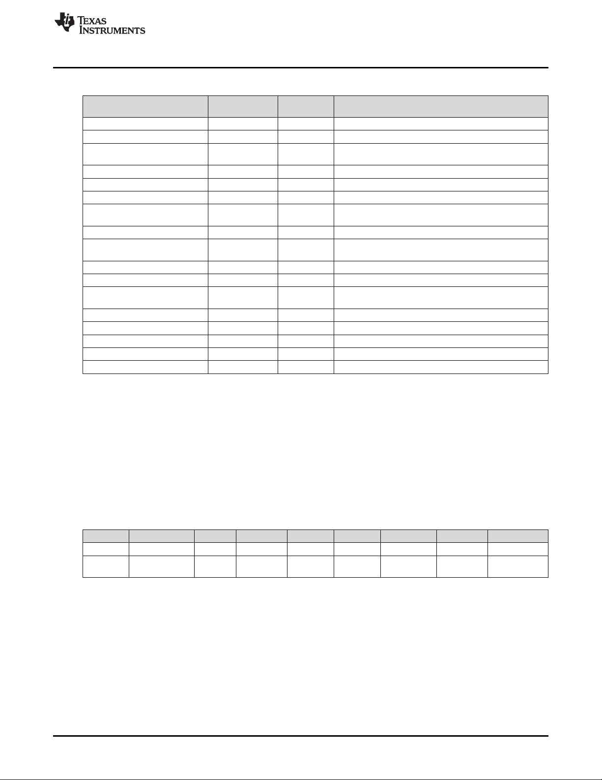
www.ti.com
EOS_START_LEARN 0x0039 Yes Initiates an EOS learning phase
EOS_ABORT_LEARN 0x003A Yes Aborts an EOS learning phase
EOS_RCELL_RRATE_LEARN 0x003B No
EOS_WARN_CLEAR 0x003C Yes Clears the EOS Warning flags
EOS_INITIAL_RCELL 0x003E Yes Used to read and write the EOS Rcell value
EOS_INITIAL_RRATE 0x003F Yes Used to read and write the EOS RRate value
RESET 0x0041 No
ACCUM_RESET 0x004B Yes Resets the accumulated charge registers
GAUGING_STATUS 0x0056 Yes
ALERT_SET 0x0068 Yes Forces ALERT pin to be set (when enabled)
ALERT_RESET 0x0069 Yes Forces ALERT pin to be reset (when enabled)
EDV_THRESHOLD 0x0073 Yes
EXIT_CAL 0x0080 No Instructs the fuel gauge to exit CALIBRATION mode
ENTER_CAL 0x0081 No Instructs the fuel gauge to enter CALIBRATION mode
ENTER_CFG_UPDATE 0x0090 Yes Enter CONFIG UPDATE mode
EXIT_CFG_UPDATE_REINIT 0x0091 Yes Exit CONFIG UPDATE mode and reinitialize
EXIT_CFG_UPDATE 0x0092 Yes Exit CONFIG UPDATE mode without reinitialize
CNTL/MAC FUNCTION
Control()/CONTROL_STATUS(): 0x00 and 0x01
Table 4-2. Control() MAC Subcommands (continued)
SUBCOMMAND
CODE
SEALED
ACCESS?
DESCRIPTION
Initiates the Initial Rcell and Initial RRate learning
procedures
Resets the device (The should only be sent in CFG
UPDATE mode.)
This MAC subcommand returns the information in the
CEDV gauging status register.
This MAC subcommand returns the value of the EDV
Threshold.
An example using the DEVICE_NUMBER() subcommand:
• Write the data bytes 0x01 0x00 to the device address 0xAA starting at command 0x00.
• Then read the response using an incremental read. To the device address 0xAB, starting at command
0x3E, read four bytes. The result would be 0x01 0x00 0x10 0x02 with the first two bytes reflecting the
subcommand, and the second two bytes representing Device Type in little endian order.
4.1.1 CONTROL_STATUS: 0x0000
A read on this command returns the 16-bit CONTROL_STATUS() data. The status word includes the
following information:
Table 4-3. CONTROL_STATUS Bit Definitions
Bit 7 Bit 6 Bit 5 Bit 4 Bit 3 Bit 2 Bit 1 Bit 0
High Byte RSVD RSVD RSVD RSVD RSVD RSVD RSVD RSVD
Low Byte
SHUTDOWN_EN = Enables low power SHUTDOWN mode when subcommand SHUTDOWN is used.
SHUTDOWN
High Byte
Low Byte
_EN
RSVD = Reserved
RSVD = Reserved
CCA = Status bit indicating the fuel gauge Coulomb Counter Calibration routine is active. The CCA routine
BCA = Status bit indicating the fuel gauge board calibration routine is active. Active when set.
RSVD = Reserved
RSVD = Reserved
RSVD CCA BCA RSVD RSVD RSVD BATT_ID0
takes place approximately one minute after the initialization and periodically as gauging conditions
change. Active when set. (See Autocalibration.)
SLUUBE8–September 2018
Submit Documentation Feedback
Copyright © 2018, Texas Instruments Incorporated
Data Commands
53
Page 54

Control()/CONTROL_STATUS(): 0x00 and 0x01
RSVD = Reserved
BATT_ID0 = Battery Identification Setting. Battery identification settings for different chemistries, used to select one of
two chemistry IDs.
0 = CEDV Profile 1
1 = CEDV Profile 2
One of these CEDV profiles is loaded it initial power. The host can modify the memory parameters to fit
the particular requirement of the system battery.
4.1.2 DEVICE_NUMBER: 0x0001
This command instructs the fuel gauge to return Device Type 0x0210 to MACData().
4.1.3 FW_VERSION: 0x0002
This command instructs the fuel gauge to return the firmware revision on MACData() in the following
format:
ddDDvvVVbbBBTTzzZZRREE, where
ddDD: Device Number
vvVV: Version
bbBB: Build number
ttTT: Firmware type.
www.ti.com
4.1.4 BOARD_OFFSET: 0x0009
This command instructs the fuel gauge to measure and store the board offset value.
4.1.5 CC_OFFSET: 0x000A
This command instructs the fuel gauge to measure the internal CC offset value.
4.1.6 CC_OFFSET_SAVE: 0x000B
This command instructs the fuel gauge to store the internal CC offset value.
4.1.7 SET_PROFILE_1: 0x0015
This command selects CEDV Profile 1.
4.1.8 SET_PROFILE_2: 0x0016
This command selects CEDV Profile 2.
4.1.9 SHUTDOWN_ENABLE: 0x001B
This command enables entry into SHUTDOWN mode with the SHUTDOWN command.
4.1.10 SHUTDOWN: 0x001C
This command puts the device into low power SHUTDOWN mode. Exit is done with a power cycle or
through the ALERT pin.
4.1.11 ACCUM_DSG_EN: 0x001E
This MAC subcommand toggles the value of ManufacturingStatus()[ACDSG_EN].
4.1.12 ACCUM_CHG_EN: 0x001F
This MAC subcommand toggles the value of ManufacturingStatus()[ACCHG_EN].
54
Data Commands
Copyright © 2018, Texas Instruments Incorporated
SLUUBE8–September 2018
Submit Documentation Feedback
Page 55

www.ti.com
4.1.13 IGNORE_SELFDSG_EN: 0x0020
This MAC subcommand toggles the value of ManufacturingStatus()[IGNORE_SD_EN].
4.1.14 PIN_CONTROL_EN: 0x0022
This command toggles control of the ALERT pin via the ALERT_SET and ALERT_RESET commands. It
is indicated by ManufacturingStatus[PCTL_EN]. Care must be taken when using this function when a true
Alert might occur. Use may cause the system to miss the Alert.
4.1.15 CAL_TOGGLE: 0x002D
Toggles the OperationStatus()[CALMD] flag
4.1.16 SEAL: 0x0030
This instructs the fuel gauge to transition from the UNSEALED state to the SEALED state. The fuel gauge
must always be set to the SEALED state for use in end-equipment.
Sending the SEAL command will set Operation Config A [DEFAULTSEAL], which will cause the gauge
to automatically reseal unless the DEFAULTSEAL bit is cleared.
4.1.17 EOS_START_LEARN: 0x0039
This MAC subcommand instructs the bq34210-Q1 device to begin a learning phase.
Control()/CONTROL_STATUS(): 0x00 and 0x01
4.1.18 EOS_ABORT_LEARN: 0x003A
This MAC subcommand instructs the bq34210-Q1 device to stop a learning phase.
4.1.19 EOS_RCELL_RRATE_LEARN: 0x003B
This MAC subcommand instructs the bq34210-Q1 device to initiate an Initial Rcell and an Initial RRate
measurement.
4.1.20 EOS_WARN_CLEAR: 0x003C
This MAC subcommand instructs the bq34210-Q1 device to clear the EOS warning bits (this includes
[DRDWARN], [RSDWARN], and [RSDLWARN]).
4.1.21 EOS_INITIAL_RCELL: 0x003E
This MAC subcommand is used to read the stored Initial_Rcell measurement or to overwrite the value
with a previously measured value.
4.1.22 EOS_INITIAL_RRATE: 0x003F
This MAC subcommand is used to read the stored Initial_RRate measurement or to overwrite the value
with a previously measured value.
4.1.23 RESET: 0x0041
This instructs the fuel gauge to perform a full reset.
NOTE: This subcommand is available only when the fuel gauge is UNSEALED, and should be used
only while in CONFIG UPDATE mode.
4.1.24 ACCUM_RESET: 0x004B
This command resets the accumulated charge registers.
SLUUBE8–September 2018
Submit Documentation Feedback
Copyright © 2018, Texas Instruments Incorporated
Data Commands
55
Page 56

Control()/CONTROL_STATUS(): 0x00 and 0x01
4.1.25 GAUGING_STATUS: 0x0056
Returns the 16-bit internal gauging status register. The most often checked flags from this register are
copied to the OperationStatus() direct read register for easier access.
Table 4-4. Gauging Status Bit Definitions
Bit 7 Bit 6 Bit 5 Bit 4 Bit 3 Bit 2 Bit 1 Bit 0
High Byte VDQ EDV2 EDV1 RSVD RSVD FCCX RSVD REST
Low Byte CF DSG EDV RSVD TC TD FC FD
High Byte
VDQ = Indicates if the current discharge cycle is NOT qualified or qualified for an FCC updated. Discharge cycle
valid for FCC update is set.
EDV2 = Indicates if measured cell voltage is above or below EDV2 threshold. Below = true when set.
EDV1 = Indicates if measured cell voltage is above or below EDV1 threshold. Below = true when set.
RSVD = Reserved
RSVD = Reserved
FCCX = Control for fcc1hz clock going into CC.
0 = fcc1hz = 1 Hz
1 = fcc1hz = 16 Hz
RSVD = Reserved
REST = Indicates if the device is in RELAXATION mode.
0 = The device has not reached relaxation.
1 = The device has reached relaxation.
Low Byte
CF = Indicates if battery conditioning is needed.
DSG = Set when in DISCHARGE or RELAXATION modes. Clear when in CHARGE mode.
EDV = Indicates if measured cell voltage is above or below EDV0 threshold. Below = true when set.
RSVD = Reserved
TC = Terminate Charge. Controlled by settings in SOC Flag Config A. (This flag is identical to
BatteryStatus()[TCA].)
TD = Terminate Discharge. Controlled by settings in SOC Flag Config A. (This flag is identical to
BatteryStatus()[TDA].)
FC = Full Charge. Controlled by settings in SOC Flag Config A and SOC Flag Config B. (This flag is identical to
BatteryStatus()[FC].)
FD = Full Discharge. Controlled by settings in SOC Flag Config B. (This flag is identical to BatteryStatus()[FD].)
www.ti.com
4.1.26 ManufacturingStatus(): 0x57
This function enables certain functions.
Table 4-5. Manufacturing Status Bit Definitions
Bit 7 Bit 6 Bit 5 Bit 4 Bit 3 Bit 2 Bit 1 Bit 0
High Byte CAL_EN RSVD RSVD RSVD RSVD RSVD RSVD RSVD
Low Byte RSVD RSVD RSVD PCTL_EN EOS_EN IGNORE_SD_EN
High Byte
CAL_EN = Set and cleared by CAL_TOGGLE, it enables calibration commands.
Low Byte
56
Data Commands
PCTL_EN = Set and cleared by PIN_CONTROL_EN, it indicates if ALERT can be controlled via ALERT_SET and
EOS_EN = When set, the EOS Determination function is enabled.
IGNORE_SD_EN = Enables user to ignore cell self-discharge
ACCHG_EN = Enables accumulated charge integration in charge direction
ACSDG_EN = Enables accumulated charge integration in discharge direction
ALERT_RESET commands (1 = yes).
Copyright © 2018, Texas Instruments Incorporated
ACCHG
_EN
SLUUBE8–September 2018
Submit Documentation Feedback
ACDSG
_EN
Page 57

www.ti.com
4.1.27 ALERT_SET: 0x0068
This command forces the ALERT pin to be set, no matter the conditions. The PIN_CONTROL_EN
command must be run to enable this feature.
4.1.28 ALERT_RESET: 0x0069
This command forces a reset on the ALERT pin. The PIN_CONTROL_EN command must be run to
enable this feature.
4.1.29 EDV_Threshold: 0x0073
This MAC subcommand returns the values of the EDV Threshold.
4.1.30 EXIT_ CAL: 0x0080
This instructs the fuel gauge to exit CALIBRATION mode.
4.1.31 ENTER_CAL: 0x0081
This instructs the fuel gauge to enter CALIBRATION mode and reset AnalogCount() to 0 if
OperationStatus()[CALMD] is set. [CALMD] is controlled by the CAL_MODE() command. Voltage must be
above 2.9 V for accurate calibration.
4.1.32 ENTER_CFG_UPDATE: 0x0090
Instructs the fuel gauge to set the OperationStatus()[DFGUPDATE] bit to 1 and enter CONFIG UPDATE
mode. This command is only available when the fuel gauge is UNSEALED.
Control()/CONTROL_STATUS(): 0x00 and 0x01
NOTE: To read the flag, the host must wait at least 2 seconds.
4.1.33 EXIT_CFG_UPDATE_REINIT: 0x0091
This command instructs the fuel gauge to exit CONFIG UPDATE mode and the gauge is reinitialized.
4.1.34 EXIT_CFG_UPDATE: 0x0092
This command instructs the fuel gauge to exit CONFIG UPDATE mode and the gauge is not reinitialized.
4.2 Temperature(): 0x06 and 0x07
This read- and write-word function returns an unsigned integer value of the temperature in units of 0.1°K
measured by the fuel gauge. See Table 4-6, Temperature Measurement Options, and Temperature
Measurement.
Table 4-6. Temperature Measurement Options
Operation
Config A
[TEMPS]
0
1 Returns external temperature read from an external thermistor.
X Returns the Temperature() value previously written.
Temperature() Read Command Temperature() Write Command
Returns internal temperature as read from an internal sensor. This data
is also available using the InternalTemperature() function.
The data is ignored.
Sets the Temperature() to be used for gauging
calculations.
SLUUBE8–September 2018
Submit Documentation Feedback
Copyright © 2018, Texas Instruments Incorporated
Data Commands
57
Page 58

Voltage(): 0x08 and 0x09
4.3 Voltage(): 0x08 and 0x09
This read-word function returns an unsigned integer value of the measured cell-pack voltage in mV with a
range of 0 to 6000 mV.
4.4 BatteryStatus(): 0x0A and 0x0B
This read-word function returns the contents of the gas gauge status register, depicting the current battery
status.
Table 4-7. Battery Status Bit Definitions
Bit 7 Bit 6 Bit 5 Bit 4 Bit 3 Bit 2 Bit 1 Bit 0
High Byte RSVD SOCLOW UTC UTD OTC OTD BATHIGH BATLOW
Low Byte SLEEP CHGINH FD FC TCA TDA CHG DSG
High Byte
RSVD = Reserved
SOCLOW = State-of-charge
UTC = Undertemperature Charge
UTD = Undertemperature Discharge
OTC = Overtemperature in charge condition is detected (Alert_1 [OTC] bit must be set).
OTD = Overtemperature in discharge condition is detected. True when set (Alert_1 [OTD] bit = 1).
BATHIGH = Battery voltage above high threshold
BATLOW = Battery voltage below low threshold
Low Byte
SLEEP = The device is operating in SLEEP mode when set. This will clear temporarily during AD measurements in
SLEEP mode.
CHGINH = Charge inhibit: If set, indicates that charging should not begin because Temperature() is outside the range
[Charge Inhibit Temp Low, Charge Inhibit Temp High]. True when set.
FD = Full discharge is detected. This flag is set and cleared based on the selected SOC Flag Config B options.
FC = Full charged is detected. This flag is set and cleared based on the selected SOC Flag Config A and SOC
Flag Config B options.
TCA = Terminate Charge Alarm. This flag is set and cleared based on the selected SOC Flag Config A options.
TDA = Terminate Discharge Alarm. This flag is set and cleared based on the selected SOC Flag Config A options.
CHG = The device has detected charge current when set.
DSG = The device is in DISCHARGE mode when set; CHARGE or RELAXATION mode when clear.
www.ti.com
4.5 Current(): 0x0C and 0x0D
This read-only function returns a signed integer value that is the instantaneous current flow through the
sense resistor. It is updated every second. Units are mA.
4.6 RemainingCapacity(): 0x10 and 0x11
This read-only command pair returns the battery remaining capacity. When CEDV Smoothing Config
[SMEN] is set, this will be the result of the smoothing engine. Otherwise, the unfiltered remaining capacity
is returned.
4.7 FullChargeCapacity(): 0x12 and 0x13
This read-only command pair returns the compensated capacity of a fully charged battery. Units are mAh.
FullChargeCapacity() is updated at regular intervals, as specified by the CEDV algorithm.
58
Data Commands
Copyright © 2018, Texas Instruments Incorporated
SLUUBE8–September 2018
Submit Documentation Feedback
Page 59

www.ti.com
4.8 AverageCurrent(): 0x14 and 0x15
This read-word function returns a signed integer value that approximates a one-minute rolling average of
the current being supplied (or accepted) through the battery terminals in mA with a range of –32,768 to
32,767.
AverageCurrent() is calculated by a rolling IIR filtered average of Current() function data with a period of
14.5 s. During the time after a reset or when switching between charge and discharge currents and before
14.5 s has elapsed, the reported AverageCurrent() = Current() function value.
Table 4-8. AverageCurrent()
Name
AverageCurrent R R R Word I2 -32768 32769 mA
SE US FA
Access
The data value Filter determines the time constant of the filter operation used in the calculation of
AverageCurrent() as follows:
AverageCurrent() = a × AverageCurrent() old + (1-a) × Current() with:
a = Filter/256; time constant = (1 s) / ln(1/a) (default = 14.5 s)
4.9 AverageTimeToEmpty(): 0x16 and 0x17
This read-only function returns an unsigned integer value of the predicted remaining battery life at the
present rate of discharge, in minutes. A value of 65,535 indicates battery is not being discharged.
AverageCurrent(): 0x14 and 0x15
Protocol Type Min Max Unit
Table 4-9. AverageTimeToEmpty()
Name
AverageTimeToEmpty R R R Word U2 0 65535 min
SE US FA
Access
4.10 AverageTimeToFull(): 0x18 and 0x19
This read-only function returns an unsigned integer value of the predicted remaining time until battery
reaches full charge, in minutes, based upon AverageCurrent(). The computation accounts for the taper
current time extension for the linear TTF computation based on a fixed AverageCurrent() rate-of-charge
accumulation. A value of 65,535 indicates the battery is not being charged.
Table 4-10. AverageTimeToFull()
Name
AverageTimeToFull R R R Word U2 0 65535 min
SE US FA
Access
4.11 AccumulatedCharge(): 0x1A and 0x1B
AccumulatedCharge() is covered in detail in Accumulated Charge Measurement.
4.12 AccumulatedChargeTime(): 0x1C and 0x1D
AccumulatedChargeTime() is covered in detail in Accumulated Charge Measurement.
Protocol Type Min Max Unit
Protocol Type Min Max Unit
4.13 LastAccumulatedCharge(): 0x1E and 0x1F
LastAccumulatedCharge() is covered in detail in Accumulated Charge Measurement.
SLUUBE8–September 2018
Submit Documentation Feedback
Copyright © 2018, Texas Instruments Incorporated
Data Commands
59
Page 60

LastAccumulatedChargeTime(): 0x20 and 0x21
4.14 LastAccumulatedChargeTime(): 0x20 and 0x21
LastAccumulatedChargeTime() is covered in detail in Accumulated Charge Measurement.
4.15 AveragePower(): 0x24 and 0x25
This read-only function returns a signed integer value of the average power during battery charging and
discharging. It is negative during discharge and positive during charge. A value of 0 indicates that the
battery is not being discharged. The value is reported in units of mW.
4.16 InternalTemperature(): 0x28 and 0x29
This read-only function returns an unsigned integer value of the internal temperature sensor in units of
0.1°K measured by the fuel gauge. This function can be useful as an additional system-level temperature
monitor if the main Temperature() function is configured for external or host-reported temperature.
4.17 CycleCount(): 0x2A and 0x2B
This read-only function returns an unsigned integer value of the number of cycles that the active cell has
experienced with a range of 0 to 65535. One cycle occurs when accumulated discharge ≥ cycle threshold.
The cycle threshold is calculated based on CEDV Gauging Configuration [CCT]:
1 = Cycle Count Percentage × FullChargeCapacity()
0 = Cycle Count Percentage × DesignCapacity().
www.ti.com
4.18 RelativeStateOfCharge(): 0x2C and 0x2D
This read-only function returns an unsigned integer value of the predicted remaining battery capacity
expressed as a percentage of FullChargeCapacity(), with a range of 0 to 100%. RelativeStateOfCharge()
= RemainingCapacity() ÷ FullChargeCapacity() rounded up to the nearest whole percentage point.
4.19 StateOfHealth(): 0x2E and 0x2F
The StateOfHealth() (SOH) read-only function returns an unsigned integer value, expressed as a
percentage of the ratio of FullChargeCapacity() over the DesignCapacity(), with a range of 0 to 100%.
StateOfHealth() = FullChargeCapacity() ÷ DesignCapacity() rounded up to the nearest whole percentage
point.
4.20 ChargingVoltage(): 0x30 and 0x31
This read-only function returns an unsigned integer value of the desired charging voltage of the battery. A
value of 65,535 indicates that the battery is requesting the maximum voltage from the battery charger.
4.21 ChargingCurrent(): 0x32 and 0x33
This read-only function returns an unsigned integer value of the desired charging current of the battery. A
value of 65,535 indicates that the battery is requesting the maximum current from the battery charger.
4.22 BLTDischargeSet(): 0x34 and 0x35
This read/write word command updates the BLT set threshold that triggers the BLT interrupt in discharge
direction, and sets the OperationStatus()[BLTINT] bit.
4.23 BLTChargeSet(): 0x36 and 0x37
The read/write word command updates the BLT set threshold that triggers the BLT interrupt in charge
direction, and sets the OperationStatus()[BLTINT] bit.
60
Data Commands
Copyright © 2018, Texas Instruments Incorporated
SLUUBE8–September 2018
Submit Documentation Feedback
Page 61

www.ti.com
4.24 OperationStatus(): 0x3A and 0x3B
This read-word function returns the contents of the internal status register.
Table 4-11. Operation Status Bit Definitions
Bit 7 Bit 6 Bit 5 Bit 4 Bit 3 Bit 2 Bit 1 Bit 0
High Byte RSVD RSVD RSVD RSVD INITCOMP CFGUPDATE RSVD RSVD
Low Byte BLT SMTH ACTHR VDQ EDV2 SEC1 SEC0 CALMD
High Byte
INITCOMP = Indicates if fuel gauge initialization is complete. This bit can only be set with battery presence. True when
set.
CFGUPDATE = Gauge is in CONFIG UPDATE mode. Gauging is suspended.
Low Byte
BLT = Battery Level Threshold Flag
Setting and clearing this flag depends upon various conditions. See Battery Level Threshold for details.
SMTH = Indicates that RemainingCapacity() accumulation is currently scaled by the smoothing engine.
ACTHR = Accumulated Charge Threshold Flag
1 = The accumulated charge was detected passing a threshold.
0 = The accumulated charge was not detected passing a threshold.
VDQ = Indicates if the current discharge cycle is NOT qualified or qualified for an FCC updated. A discharge cycle
valid for FCC update is set.
EDV2 = Indicates if measured cell voltage is above or below EDV2 threshold. Below = true when set.
SEC[1:0] = Defines Current Security Access
11 = Sealed Access
10 = Unsealed Access
01 = Full Access
00 = Unused
CALMD = Toggles with 0x2D command to enable/disable CALIBRATION mode
OperationStatus(): 0x3A and 0x3B
4.25 DesignCapacity(): 0x3C and 0x3D
This read-only function returns the value stored in Design Capacity mAh. This is intended to be the
theoretical or nominal capacity of a new pack, and is used for the calculation of StateOfHealth().
4.26 ManufacturerAccessControl(): 0x3E and 0x3F
This read-write word function returns the subcommand that is currently active for reads on MACData().
Word writes to this function will set a subcommand. Commands that do not require data will run
immediately (identical to writes to Control()).
4.27 MACData(): 0x40 through 0x5F
This read-write block will return the result data for the currently active subcommand. It is recommended to
start the read at ManufacturerAccessControl() to verify the active subcommand.
Writes to this block are used to provide data to a subcommand when required.
4.28 MACDataSum(): 0x60
This read-write function returns the checksum of the current subcommand and data block.
Writes to this register provide the checksum necessary in order to run subcommands that require data.
The checksum is calculated as the complement of the sum of the ManufacturerAccessControl() and the
MACData() bytes. MACDataLen() determines the number of bytes of MACData() that are included in the
checksum.
SLUUBE8–September 2018
Submit Documentation Feedback
Copyright © 2018, Texas Instruments Incorporated
Data Commands
61
Page 62

MACDataLen(): 0x61
4.29 MACDataLen(): 0x61
This read-write function returns the number of bytes of MACData() that are part of the response and
included in MACDataSum().
Writes to this register provide the number of bytes in MACData() that should be processed as part of the
subcommand.
Subcommands that require block data are not run until MACDataSum() and MACDataLen() are written
together as a word.
4.30 EOSLearnStatus(): 0x64 and 0x65
This command returns various flags providing information on the EOS Determination function.
Bit 7 Bit 6 Bit 5 Bit 4 Bit 3 Bit 2 Bit 1 Bit 0
LSB LCTO LFAULT LABRT LCMD LPER LRLX LCHG LDSG
MSB LDONE LRES LRSTOR LCTLEDGE LUCD LDPAM LDPAT LDPAI
RSVD = Reserved. Do not use.
LCTO = Learn Charge Time Out
This bit is set = 1 if the bq34210-Q1 device is in LEARN CHARGE mode and detects the
charging time has exceeded Learn Charge Time Limit. This bit is reset to 0 when a new
learning phase begins.
1 = A learn excessive charge time was detected.
0 = A learn excessive charge time was not detected.
LFAULT = Learn Fault Flag
This bit is set = 1 whenever a learning phase is terminated for any reason other than a valid
termination, and also if any other fault (such as in GaugingStatus() or BatteryStatus()) occurred
during the learning phase. The bit will be reset to 0 when a new learning phase begins.
1 = A learning phase was stopped.
0 = A learning phase was not stopped.
LABRT = Learn Abort on Command
This bit is set = 1 whenever a learning phase was stopped by the host. A bit that was set = 1
will be reset to 0 when a new learning phase begins.
1 = A requested learning phase was stopped.
0 = A requested learning phase was not stopped.
LCMD = Learn Command
This bit is set = 1 if learning is activated and a learning phase was started by a command. The
bit will remain high until the learning phase is complete (including charging, learning,
discharging, and related calculations).
1 = The device is in a command-initiated learning phase.
0 = The device is not in a command-initiated learning phase.
LPER = Learn Periodic Mode
This bit is set = 1 if learning is activated and the bq34210-Q1 device is in PERIODIC LEARN
mode. This bit is only set while the device is in a learning phase.
1 = The device is in PERIODIC LEARN mode.
0 = The device is not in PERIODIC LEARN mode.
LRLX = Learn RELAXATION mode
This bit is set = 1 if learning is activated and the bq34210-Q1 device is in a RELAXATION
mode during learning. This means the cell is waiting to detect a relaxed condition; it may not
have achieved relaxation yet.
www.ti.com
62
Data Commands
Copyright © 2018, Texas Instruments Incorporated
SLUUBE8–September 2018
Submit Documentation Feedback
Page 63

www.ti.com
LCHG = Learn CHARGE mode
LDSG = Learn DISCHARGE mode
LDONE = Learn Done
LRES = Learned Rcell
EOSLearnStatus(): 0x64 and 0x65
1 = The device is in RELAXATION mode during learning.
0 = The device is not in RELAXATION mode during learning.
This bit is set = 1 if the bq34210-Q1 device is in learn CHARGE mode. If the device is
controlling a charger directly through a device pin, then the value of this signal will be reflected
on the selected pin. If instead the host is controlling the charger, then this bit can be used to
signal the host to initiate charging.
1 = A LEARN CHARGE mode is in progress.
0 = A LEARN CHARGE mode is not in progress.
This bit is set = 1 if the bq34210-Q1 device is in automatic END-OF-SERVICE
DETERMINATION mode and the device intends to begin a Learn Discharge Phase. It is set = 0
when the device intends the Learn Discharge Phase to end. If the device is controlling the
discharge directly using the LEN pin, then the LEN pin will reflect the value of LDSG. If instead
the host is controlling the Learn Discharge Current, this bit will signal the host to enable the
Learn Discharge Current.
1 = A Learn Discharge Phase was requested or is in progress.
0 = A Learn Discharge Phase is requested to stop or was stopped.
This bit is set = 1 when a valid learning phase has completed.
1 = A valid learning phase was completed.
0 = A valid learning phase was not completed.
This bit is set = 1 when the bq34210-Q1 device has completed the computation of a new Rcell
value during the present learning phase. This bit is cleared when the learning phase is
complete.
1 = A new value of Rcell was acquired.
0 = A new value of Rcell has not yet been acquired.
LRSTOR = Learn Voltage Restore
This bit is set = 1 if whenever the Learn Discharge Phase is complete and the voltage can be
restored back to its original level. This bit is cleared when the learning phase is complete.
1 = A Learning Discharge Phase has completed, and the voltage can be restored.
0 = The device has completed the learning phase.
LCTLEDGE = Learn Discharge Flag Edge Detected
This bit is set = 1 if whenever LDSG changes state. This can be used by the host as an
interrupt to recognize when a learning load should be activated and when it should be disabled.
This bit clears when the register is read.
1 = A change in LDSG was detected (this is only applicable when LENCTL=0).
0 = A change in LDSG was not detected.
LUCD = Learn Unexpected Current Detected
This bit is set when the device is in LEARNING mode (but not in the Learn Discharge Phase),
and a current is detected differently than what is expected. It is set if the device is attempting to
charge or relax, and a discharge current in excess of Discharge Detection Threshold is
detected. It is also set if the device is in a RELAXATION mode and a charging current in
excess of Charge Detection Threshold is detected. This detection also terminates the
learning phase, and this bit will remain set as a flag to the host as to why the learning phase
was stopped. This bit will be reset to 0 when a new learning phase begins.
1 = An unexpected system-related current was detected during a learning charge or learning
relax period.
0 = An unexpected system-related current was not detected.
SLUUBE8–September 2018
Submit Documentation Feedback
Copyright © 2018, Texas Instruments Incorporated
Data Commands
63
Page 64

EOSSafetySatus(): 0x66 and 0x67
LDPAM = Learn Discharge Phase Abort on Timer
This bit is set = 1 when a Learn Discharge Phase was requested by the host but was declined
due to the time since the last Learn Discharge Phase was less than the interval specified in
Minimum Learn Time. A bit that was set = 1 will be reset to 0 when Minimum Learn Time
has passed.
1 = A requested Learn Discharge Phase was declined.
0 = A requested Learn Discharge Phase was not declined.
LDPAT = Learn Discharge Phase Abort on Temperature
This bit is set = 1 when a Learn Discharge Phase was initiated but was stopped due to
Temperature() measured outside the range allowed by Learn Min Temperature and Learn
Max Temperature. A bit that was set = 1 will be reset to 0 when a new Learn Discharge Phase
begins.
1 = A Learn Discharge Phase was stopped.
0 = A Learn Discharge Phase was not stopped.
LDPAI = Learn Discharge Phase Abort on Current
This bit is set = 1 when a Learn Discharge Phase was initiated but was stopped due to
Current() measured outside the range allowed by Learn Discharge Current and Learn
Discharge Current Boundary. A bit that was set = 1 will be reset to 0 when a new Learn
Discharge Phase begins.
1 = A Learn Discharge Phase was stopped.
0 = A Learn Discharge Phase was not stopped.
www.ti.com
4.31 EOSSafetySatus(): 0x66 and 0x67
This command returns flags generated by the EOS Determination function.
Bit 7 Bit 6 Bit 5 Bit 4 Bit 3 Bit 2 Bit 1 Bit 0
LSB RSVD RSVD RSVD RSVD RSVD
MSB RSVD RSVD RSVD RSVD RSVD RSDLWARN RSDWARN DRDWARN
Legend = RSVD = Reserved. Do not use.
RSDLALERT = Resistance Slope Decisioning Long-Term Alert
This bit is set = 1 if the bq34210-Q1 EOS Determination function detects the condition described
above to trigger the [RSDLALERT] signal. This signal is cleared when the register is read or if a
new learning phase begins.
1 = An RSDLALERT was detected.
0 = An RSDLALERT was not detected.
RSDALERT = Resistance Slope Decisioning Alert
This bit is set = 1 if the bq34210-Q1 EOS Determination function detects the condition described
above to trigger the [RSDALERT] signal. This signal is cleared when the register is read or if a
new learning phase begins.
1 = An RSDALERT was detected.
0 = An RSDALERT was not detected.
DRDALERT = Direct Resistance Decisioning Alert
This bit is set = 1 if the bq34210-Q1 EOS Determination function detects the condition described
above to trigger the [DRDALERT] signal. This signal is cleared when the register is read or if a
new learning phase begins.
1 = A DRDALERT was detected.
0 = A DRDALERT was not detected.
RSDL
ALERT
RSDALERT DRDALERT
64
Data Commands
Copyright © 2018, Texas Instruments Incorporated
SLUUBE8–September 2018
Submit Documentation Feedback
Page 65

www.ti.com
RSDLWARN = Resistance Slope Decisioning Long-Term Warning
This bit is set = 1 if the bq34210-Q1 EOS Determination function detects the condition described
above to trigger the [RSDLWARN] signal. This signal is NOT cleared when the register is read. It
can only be cleared using the command EOS_WARNCLR().
1 = An RSDLWARN was detected.
0 = An RSDLWARN was not detected.
RSDWARN = Resistance Slope Decisioning Warning
This bit is set = 1 if the bq34210-Q1 EOS Determination function detects the condition described
above to trigger the [RSDWARN] signal. This signal is NOT cleared when the register is read. It
can only be cleared using the command EOS_WARNCLR().
1 = An RSDWARN was detected.
0 = An RSDWARN was not detected.
DRDWARN = Direct Resistance Decisioning Warning
This bit is set = 1 if the bq34210-Q1 EOS Determination function detects the condition described
above to trigger the [DRDWARN] signal. This signal is NOT cleared when the register is read. It
can only be cleared using the command EOS_WARNCLR().
1 = A DRDWARN was detected.
0 = A DRDWARN was not detected.
4.32 EOSStatus(): 0x68
This command returns additional flags that provide information related to the EOS Determination function.
EOSStatus(): 0x68
Bit 7 Bit 6 Bit 5 Bit 4 Bit 3 Bit 2 Bit 1 Bit 0
SRRL SRCL RSVD LTI RSDLI RCELLR IRRCOMP IRCOMP
Legend = RSVD = Reserved. Do not use.
SRRL = Initial RRate Learning in Progress
This bit is set = 1 if the bq34210-Q1 EOS Determination function begins the required learning
phases to calculate a value of Initial RRate, generally after an EOS_RCELL_RRATE_LEARN()
command was issued. The bit will clear when the Initial RRate learning and computation is
complete.
SRCL = Initial Rcell Learning in Progress
This bit is set = 1 if the bq34210-Q1 EOS Determination function begins the required learning
phases to calculate a value of Initial Rcell, generally after an EOS_RCELL_RRATE_LEARN()
command was issued. The bit will clear when the Initial Rcell learning and computation is complete.
LTI = Learn Timer Invalid
This bit is set = 1 if the bq34210-Q1 EOS Determination function detects that the timer was
interrupted since the most recent Rcell was calculated. In this case, the RSD algorithm must capture
two new Rcell values separated in time to calculate a new value of RRate and evaluate this for
corresponding alerts and warnings.
1 = A timer interruption was detected.
0 = A timer interruption was not detected.
RSDLI = Resistance Slope Decisioning Long-Term Invalid
This bit is set = 1 if the bq34210-Q1 EOS Determination function detects that the timer was
interrupted since the Initial RRate was calculated. In this case, the RSDL algorithm will no longer
trigger an alert or warning.
1 = A timer interruption was detected.
0 = A timer interruption was not detected.
SLUUBE8–September 2018
Submit Documentation Feedback
Copyright © 2018, Texas Instruments Incorporated
Data Commands
65
Page 66

AnalogCount(): 0x79
RCELLR = Rcell Reduction Alert
This bit is set = 1 if the bq34210-Q1 EOS Determination function detects a value of Rcell that is
more than 2% below the previous value of Rcell. This signal is cleared when the register is read or if
a new learning phase begins.
1 = A reduction in Rcell was detected.
0 = A reduction in Rcell was not detected.
IRRCOMP = Initial RRate Calculation Complete
This bit is set = 1 if the bq34210-Q1 EOS Determination function has completed the required
learning phases to calculate a value of Initial RRate. This bit is reset when a new Initial RRate
calculation is triggered until the new calculation is complete. This bit can be written by the host
through loading data flash if the host chooses to initialize the device with previously calculated Initial
RRate data and not trigger a new Initial RRate calculation.
1 = Initial RRate was obtained.
0 = Initial RRate was not obtained.
IRCOMP = Initial Rcell Calculation Complete
This bit is set = 1 if the bq34210-Q1 EOS Determination function has completed the required
learning phases to calculate a value of Initial Rcell. This bit is reset when a new Initial Rcell
calculation is triggered until the new calculation is complete. This bit can be written by the host
through loading data flash if the host chooses to initialize the device with previously calculated Initial
Rcell data and not trigger a new Initial Rcell calculation.
1 = Initial Rcell was obtained.
0 = Initial Rcell was not obtained.
www.ti.com
4.33 AnalogCount(): 0x79
This read-only function returns the analog counter. The value is incremented every time the analog data
for calibration was updated.
4.34 RawCurrent(): 0x7A and 0x7B
This read-only function returns the raw data from the coulomb counter.
4.35 RawVoltage(): 0x7C and 0x7D
This read-only function returns the raw data from the cell voltage reading.
4.36 RawIntTemp(): 0x7E and 0x7F
This read-only function returns the raw data from the internal temperature measurement.
4.37 RawExtTemp(): 0x80 and 0x81
This read-only function returns the raw data from the external temperature measurement.
66
Data Commands
Copyright © 2018, Texas Instruments Incorporated
SLUUBE8–September 2018
Submit Documentation Feedback
Page 67

5.1 Accessing the Data Memory
The data memory contains initialization, default, cell status, calibration, configuration, and user
information. Most data memory parameters reside in volatile RAM initialized by associated parameters
from ROM. The data memory can be accessed two different ways, depending in which mode the fuel
gauge is operating and what data is being accessed.
Most data memory locations are only accessible in the UNSEALED mode by use of the evaluation
software (bqStudio + EV2400) or by data memory block transfers. These locations should be optimized
and/or fixed during the development and manufacturing processes. They become part of a golden image
file and then can be written to multiple battery packs. Once established, the values generally remain
unchanged during end-equipment operation.
5.2 Device Access Modes
The fuel gauge provides two access modes, UNSEALED and SEALED, that control the data memory
access permissions. The default access mode of the fuel gauge is UNSEALED, so the system processor
must send a SEALED subcommand after a gauge reset to use the data protection feature.
Chapter 5
SLUUBE8–September 2018
Data Memory Interface
5.3 Sealing and Unsealing Data Memory Access
The fuel gauge implements a key-access scheme to transition from SEALED to UNSEALED mode. Once
SEALED via the associated subcommand, a unique set of two keys must be sent to the fuel gauge via the
Control() command to return to UNSEALED mode. The keys must be sent consecutively, with no other
data being written to the Control() register in between. When in SEALED mode, the OperationStatus[SEC]
bits (SEC1,SEC0) are set to 11; but when the Sealed to Unsealed keys are correctly received by the fuel
gauge, the [SEC] bits (SEC1,SEC0) transition to 10.
The unseal code is 0x1404 followed by 0x7236 and must be sent in little endian order.
Write 0xAA 0x00 0x04 0x14
Write 0xAA 0x00 0x36 0x72
The two commands must be run within 4 seconds and with no other commands in between them or the
device will remain sealed.
SLUUBE8–September 2018
Submit Documentation Feedback
Copyright © 2018, Texas Instruments Incorporated
Data Memory Interface
67
Page 68
Chapter 6
SLUUBE8–September 2018
Data Memory Summary
The Data Memory Table shows the data memory locations, including their defaults and minimum and
maximum values, that are available to customers.
Table 6-1. Data Type Decoder
Type Min Value Max Value
F4 ±9.8603 × 10
–39
±5.707267 × 10
H1 0x00 0xFF
H2 0x00 0xFFFF
H4 0x00 0xFFFF FFFF
I1 –128 127
I2 –32768 32767
I4 −2,147,483,648 2,147,483,647
Sx 1-byte string x-byte string
U1 0 255
U2 0 65535
U4 0 4,294,967,295
37
Table 6-2. Data Memory Table
Class Subclass Address Name Type Min Value Max Value Default Units
Calibration Offset 0x91F2 Board Offset I1 –128 127 0 Counts
Calibration Offset 0x91F3 Int Temp Offset I1 –128 127 0 0.1°C
Calibration Offset 0x91F4 Ext Temp Offset I1 –128 127 0 0.1°C
Calibration Offset 0x91F5 Pack V Offset I1 –128 127 0 mV
Calibration Temperature 0x91F6 Internal Model Coefficient 1 I2 –32768 32767 0 Num
Calibration Temperature 0x91F8 Internal Model Coefficient 2 I2 –32768 32767 0 Num
Calibration Temperature 0x91FA Internal Model Coefficient 3 I2 –32768 32767 –13356 Num
Calibration Temperature 0x91FC Internal Model Coefficient 4 I2 –32768 32767 6661 Num
Calibration Temperature 0x91FE External Model Coefficient 1 I2 –32768 32767 –11130 Num
Calibration Temperature 0x9200 External Model Coefficient 2 I2 –32768 32767 19142 Num
Calibration Temperature 0x9202 External Model Coefficient 3 I2 –32768 32767 –19262 Num
Calibration Temperature 0x9204 External Model Coefficient 4 I2 –32768 32767 28203 Num
Calibration Temperature 0x9206 External Model Coefficient 5 I2 –32768 32767 892 Num
Calibration Temperature 0x9208
Calibration Temperature 0x920A
Calibration Temperature 0x920C
Calibration Temperature 0x920E
Calibration Temperature 0x9210 RC0 I2 –32768 32767 11703 Counts
Calibration Temperature 0x9212 Voltage Comp Coefficient 1 I2 –32768 32767 7320 Num
Calibration Temperature 0x9214 Voltage Comp Coefficient 2 I2 –32768 32767 723 Num
Calibration Temperature 0x9216 Voltage Comp Coefficient 3 I2 –32768 32767 –71 Num
External Model Coefficient b
1
External Model Coefficient b
2
External Model Coefficient b
3
External Model Coefficient b
4
I2 –32768 32767 328 Num
I2 –32768 32767 –605 Num
I2 –32768 32767 –2443 Num
I2 –32768 32767 4696 Num
68
Data Memory Summary
SLUUBE8–September 2018
Submit Documentation Feedback
Copyright © 2018, Texas Instruments Incorporated
Page 69

www.ti.com
Table 6-2. Data Memory Table (continued)
Class Subclass Address Name Type Min Value Max Value Default Units
Calibration Temperature 0x9218 Voltage Comp Input Multiplier U1 0 255 48 Num
Calibration Temperature 0x9219 Voltage Comp Output Divisor I2 –32768 32767 256 Num
Calibration Current 0x921B Filter U1 0 255 239 Num
Calibration Current 0x921C Deadband U1 0 255 5 mA
Calibration Current 0x921D CC Deadband U1 0 255 68 73 nV
Calibration Current 0x9233 CC Offset I2 –32767 32767 0 Counts
Calibration Current 0x9237 CC Gain F4 –4.0e+00 4.0e+00 –0.231 —
Calibration Current 0x923B CC Delta F4 –3.0e+06 3.0e+06
Charger Control Charge Inhibit Cfg 0x923F Chg Inhibit Temp Low I2 –400 1200 0 0.1°C
Charger Control Charge Inhibit Cfg 0x9241 Chg Inhibit Temp High I2 –400 1200 450 0.1°C
Charger Control Charge Inhibit Cfg 0x9243 Temp Hys I2 0 100 50 0.1°C
Charger Control
Charger Control
Charger Control
Charger Control
Charger Control
Charger Control
Charger Control
Charger Control
Charger Control
Charger Control
Charger Control
Charger Control
Charger Control
Charger Control
Charger Control
Charger Control
Safety OTC 0x9292 OT Chg I2 0 1200 550 0.1°C
Safety OTC 0x9294 OT Chg Time U1 0 60 2 s
Safety OTC 0x9295 OT Chg Recovery I2 0 1200 500 0.1°C
Safety OTD 0x9297 OT Dsg I2 0 1200 600 0.1°C
Safety OTD 0x9299 OT Dsg Time U1 0 60 2 s
Safety OTD 0x929A OT Dsg Recovery I2 0 1200 550 0.1°C
Safety UTC 0x929C UT Chg I2 –400 1200 0 0.1°C
Safety UTC 0x929E UT Chg Time U1 0 60 2 s
Safety UTC 0x929F UT Chg Recovery I2 –400 1200 50 0.1°C
Safety UTD 0x92A1 UT Dsg I2 –400 1200 0 0.1°C
Safety UTD 0x92A3 UT Dsg Time U1 0 60 2 s
Safety UTD 0x92A4 UT Dsg Recovery I2 –400 1200 50 0.1°C
Safety BATLOW 0x92A6 Battery Low Set Threshold I2 0 5000 3150 mV
JEITA
Temperature
JEITA
Temperature
JEITA
Temperature
JEITA
Temperature
Charge
Termination
Charge
Termination
Charge
Termination
Charge
Termination
NiMH Charge
Termination
NiMH Charge
Termination
NiMH Charge
Termination
NiMH Charge
Termination
NiMH Charge
Termination
NiMH Charge
Termination
NiMH Charge
Termination
NiMH Charge
Termination
0x9245 T1 Temp I2 –400 1200 0 0.1°C
0x9247 T2 Temp I2 –400 1200 100 0.1°C
0x9249 T3 Temp I2 –400 1200 450 0.1°C
0x924B T4 Temp I2 –400 1200 550 0.1°C
0x924D Maintenance Current I2 0 1000 0 mA
0x924F Taper Current I2 0 1000 100 mA
0x9251 Minimum Taper Capacity I2 0 1000 25 0.01 mAh
0x9253 Current Taper Window U1 0 60 40 s
0x9254 Delta Temperature I2 –400 1200 30 0.1°C
0x9256 Delta Temperature Time U2 0 255 100 s
0x9258 Holdoff Time U2 0 255 180 s
0x925A Holdoff Current I2 0 32767 240 mA
0x925C Holdoff Temperature I2 –400 1200 250 0.1°C
0x925E Cell Negative Delta Voltage I2 0 32767 17 mV
0x9260 Cell Negative Delta Time U1 0 255 16 s
0x9261
Cell Negative Delta Qual
Voltage
I2 0 32767 2400 mV
–283945.
0625
—
SLUUBE8–September 2018
Submit Documentation Feedback
Copyright © 2018, Texas Instruments Incorporated
Data Memory Summary
69
Page 70

www.ti.com
Table 6-2. Data Memory Table (continued)
Class Subclass Address Name Type Min Value Max Value Default Units
Safety BATLOW 0x92A8 Battery Low Time U1 0 60 2 s
Safety BATLOW 0x92A9 Battery Low Clear Threshold I2 0 5000 3400 mV
Safety BATHIGH 0x92AB Battery High Set Threshold I2 0 5000 4300 mV
Safety BATHIGH 0x92AD Battery High Time U1 0 60 2 s
Safety BATHIGH 0x92AE Battery High Clear Threshold I2 0 5000 4200 mV
Safety SOCLOW 0x92B0 SOC Low Threshold U1 0 100 10 %
Safety SOCLOW 0x92B1 SOC Low Recovery U1 0 100 30 %
Configuration Registers 0x9263 Operation Config A H2 0x0000 0xFFFF 0x0484 Hex
Configuration Registers 0x9272 Device Type H2 0x0000 0xFFFF 0x0210 Hex
Configuration Power 0x9277 Sleep Current I2 0 100 10 mA
Configuration Power 0x9279 Bus Low Time U1 0 255 5 s
Configuration Power 0x927A Offset Cal Inhibit Temp Low I2 –400 1200 50 0.1°C
Configuration Power 0x927C Offset Cal Inhibit Temp High I2 –400 1200 450 0.1°C
Configuration Power 0x927E Sleep Voltage Time U1 0 100 20 s
Configuration Power 0x927F Sleep Current Time U1 0 255 20 s
Configuration
Configuration
Configuration
Configuration
Configuration
Configuration
Configuration SOC 0x92ED Flag Config A H2 0x0 0x0FFF 0x0C8C Hex
Configuration SOC 0x92EF Flag Config B H1 0x0 0xFF 0x8C Hex
Settings Configuration 0x9266 Alert_0 Config H1 0x00 0xFF 0x00 Hex
Settings Configuration 0x9267 Alert_1 Config H1 0x00 0xFF 0x00 Hex
Settings Configuration 0x9268 Alert_2 Config H1 0x00 0xFF 0x00 Hex
Settings Configuration 0x9269 Alert_3 Config H1 0x00 0xFF 0x00 Hex
Settings Configuration 0x926A Alert_4 Config H1 0x00 0xFF 0x00 Hex
Settings Configuration 0x926B Alert_5 Config H1 0x00 0xFF 0x00 Hex
Settings Configuration 0x926C Alert_6 Config H1 0x00 0xFF 0x00 Hex
Settings Configuration 0x930A EOS Configuration H1 0x0 0x0F 0x00 Hex
Settings
Settings
Settings Manufacturing 0x9308 Mfg Status Init H2 0x0 0xFFFF 0x0007 Hex
Gas Gauging Cycle 0x92EB Cycle Count Percentage U1 0 100 90 %
Gas Gauging FD 0x92F0 Set Voltage Threshold I2 0 5000 3000 mV
Gas Gauging FD 0x92F2 Clear Voltage Threshold I2 0 5000 3100 mV
Gas Gauging FD 0x92F4 Set % RSOC Threshold U1 0 100 0 %
Gas Gauging FD 0x92F5 Clear % RSOC Threshold U1 0 100 5 %
Gas Gauging FC 0x92F6 Set Voltage Threshold I2 0 5000 4200 mV
Gas Gauging FC 0x92F8 Clear Voltage Threshold I2 0 5000 4100 mV
Gas Gauging FC 0x92FA Set % RSOC Threshold U1 0 100 100 %
Gas Gauging FC 0x92FB Clear % RSOC Threshold U1 0 100 95 %
Gas Gauging TD 0x92FC Set Voltage Threshold I2 0 5000 3200 mV
Gas Gauging TD 0x92FE Clear Voltage Threshold I2 0 5000 3300 mV
Gas Gauging TD 0x9300 Set % RSOC Threshold U1 0 100 6 %
Current
Thresholds
Current
Thresholds
Current
Thresholds
Current
Thresholds
Current
Thresholds
Current
Thresholds
Accumulated
Charge
Accumulated
Charge
0x9284
0x9286 Charge Detection Threshold I2 0 2000 75 mA
0x9288 Quit Current I2 0 1000 40 mA
0x928A Discharge Relax Time U2 0 8191 60 s
0x928C Charge Relax Time U1 0 255 60 s
0x928D Quit Relax Time U1 0 63 1 s
0x928E
0x9290
Discharge Detection
Threshold
Accum Charge Positive
Threshold
Accum Charge Negative
Threshold
I2 0 2000 60 mA
I2 0 32767 1000 mAh
I2 0 32767 1000 mAh
70
Data Memory Summary
SLUUBE8–September 2018
Submit Documentation Feedback
Copyright © 2018, Texas Instruments Incorporated
Page 71

www.ti.com
Table 6-2. Data Memory Table (continued)
Class Subclass Address Name Type Min Value Max Value Default Units
Gas Gauging TD 0x9301 Clear % RSOC Threshold U1 0 100 8 %
Gas Gauging TC 0x9302 Set Voltage Threshold I2 0 5000 4200 mV
Gas Gauging TC 0x9304 Clear Voltage Threshold I2 0 5000 4100 mV
Gas Gauging TC 0x9306 Set % RSOC Threshold U1 0 100 100 %
Gas Gauging TC 0x9307 Clear % RSOC Threshold U1 0 100 95 %
Gas Gauging
Gas Gauging
Gas Gauging
Gas Gauging
Gas Gauging
Gas Gauging
Gas Gauging
Gas Gauging
Gas Gauging
Gas Gauging CEDV Cfg 0x92DE RemCap Init Percent U1 0 110 100 %
Gas Gauging CEDV Profile 1 0x9345 Gauging Configuration H2 0x0 0x1FFF 0x102A Hex
Gas Gauging CEDV Profile 1 0x9347 Full Charge Capacity I2 0 32767 3000 mAh
Gas Gauging CEDV Profile 1 0x9349 Design Capacity I2 0 32767 2200 mAh
Gas Gauging CEDV Profile 1 0x934D Design Voltage I2 0 32767 3700 mV
Gas Gauging CEDV Profile 1 0x934F Charge Termination Voltage I2 0 1000 100 mV
Gas Gauging CEDV Profile 1 0x9351 EMF U2 0 65535 3743 —
Gas Gauging CEDV Profile 1 0x9353 C0 U2 0 65535 149 —
Gas Gauging CEDV Profile 1 0x9355 R0 U2 0 65535 867 —
Gas Gauging CEDV Profile 1 0x9357 T0 U2 0 65535 4030 —
Gas Gauging CEDV Profile 1 0x9359 R1 U2 0 65535 316 —
Gas Gauging CEDV Profile 1 0x935B TC U1 0 255 9 —
Gas Gauging CEDV Profile 1 0x935C C1 U1 0 255 0 —
Gas Gauging CEDV Profile 1 0x935D Age Factor U1 0 255 0 —
Gas Gauging CEDV Profile 1 0x935E Fixed EDV 0 I2 0 32767 3031 mV
Gas Gauging CEDV Profile 1 0x9360 EDV 0 Hold Time U1 1 255 1 s
Gas Gauging CEDV Profile 1 0x9361 Fixed EDV 1 I2 0 32767 3385 mV
Gas Gauging CEDV Profile 1 0x9363 EDV 1 Hold Time U1 1 255 1 s
Gas Gauging CEDV Profile 1 0x9364 Fixed EDV 2 I2 0 32767 3501 mV
Gas Gauging CEDV Profile 1 0x9366 EDV 2 Hold Time U1 1 255 1 s
Gas Gauging CEDV Profile 1 0x9367 Voltage 0% DOD I2 –32768 32767 4173 mV
Gas Gauging CEDV Profile 1 0x9369 Voltage 10% DOD I2 –32768 32767 4043 mV
Gas Gauging CEDV Profile 1 0x936B Voltage 20% DOD I2 –32768 32767 3925 mV
Gas Gauging CEDV Profile 1 0x936D Voltage 30% DOD I2 –32768 32767 3821 mV
Gas Gauging CEDV Profile 1 0x936F Voltage 40% DOD I2 –32768 32767 3725 mV
Gas Gauging CEDV Profile 1 0x9371 Voltage 50% DOD I2 –32768 32767 3656 mV
Gas Gauging CEDV Profile 1 0x9373 Voltage 60% DOD I2 –32768 32767 3619 mV
Gas Gauging CEDV Profile 1 0x9375 Voltage 70% DOD I2 –32768 32767 3582 mV
Gas Gauging CEDV Profile 1 0x9377 Voltage 80% DOD I2 –32768 32767 3515 mV
Gas Gauging CEDV Profile 1 0x9379 Voltage 90% DOD I2 –32768 32767 3439 mV
Gas Gauging CEDV Profile 1 0x937B Voltage 100% DOD I2 –32768 32767 2713 mV
CEDV
Configuration
CEDV
Configuration
CEDV
Configuration
CEDV
Configuration
CEDV
Configuration
CEDV
Configuration
CEDV
Configuration
CEDV
Configuration
CEDV
Configuration
0x92BE Battery Low % U2 0 65535 700 .01%
0x92C8 Learning Low Temp U1 0 255 119 0.1°C
0x92D1 OverLoad Current I2 0 32767 3400 mA
0x92D5 Self Discharge Rate U1 0 255 20
0x92D6 Electronics Load I2 0 255 0 3 μA
0x92D8 Near Full I2 0 32767 200 mAh
0x92DA Reserve Capacity I2 0 32767 0 mAh
0x92DC Chg Eff U1 0 100 100 %
0x92DD Dsg Eff U1 0 100 100 %
0.01%/da
y
SLUUBE8–September 2018
Submit Documentation Feedback
Copyright © 2018, Texas Instruments Incorporated
Data Memory Summary
71
Page 72

www.ti.com
Table 6-2. Data Memory Table (continued)
Class Subclass Address Name Type Min Value Max Value Default Units
Gas Gauging CEDV Profile 1 0x937D JEITA Charge Current T1-T2 I2 0 32767 300 mA
Gas Gauging CEDV Profile 1 0x937F JEITA Charge Current T2-T3 I2 0 32767 1100 mA
Gas Gauging CEDV Profile 1 0x9381 JEITA Charge Current T3-T4 I2 0 32767 660 mA
Gas Gauging CEDV Profile 1 0x9383 JEITA Charge Voltage T1-T2 I2 0 32767 4100 mV
Gas Gauging CEDV Profile 1 0x9385 JEITA Charge Voltage T2-T3 I2 0 32767 4200 mV
Gas Gauging CEDV Profile 1 0x9387 JEITA Charge Voltage T3-T4 I2 0 32767 4100 mV
Gas Gauging
Gas Gauging
Gas Gauging
Gas Gauging
Gas Gauging
Gas Gauging
End Of Service
End Of Service
End Of Service
End Of Service
End Of Service
End Of Service
End Of Service
End Of Service
End Of Service
End Of Service
End Of Service
End Of Service
End Of Service
End Of Service
End Of Service
End Of Service
End Of Service
End Of Service
End Of Service
End Of Service
End Of Service
CEDV Smoothing
Config
CEDV Smoothing
Config
CEDV Smoothing
Config
CEDV Smoothing
Config
CEDV Smoothing
Config
CEDV Smoothing
Config
Resistance
Learning
Resistance
Learning
Resistance
Learning
Resistance
Learning
Resistance
Learning
Resistance
Learning
Resistance
Learning
Resistance
Learning
Resistance
Learning
Resistance
Learning
Resistance
Learning
Resistance
Learning
Resistance
Learning
Resistance
Learning
Resistance
Learning
Resistance
Learning
Direct Resistance
Decision
Direct Resistance
Decision
Direct Resistance
Decision
Direct Resistance
Decision
Direct Resistance
Decision
0x92DF Smoothing Config H1 0x00 0xFF 0x08 Hex
0x92E0 Smoothing Start Voltage I2 0 5000 3700 mV
0x92E2 Smoothing Delta Voltage I2 0 5000 100 mV
0x92E4 Max Smoothing Current U2 0 65535 8000 mA
0x92E9 EOC Smooth Current U1 0 10 2 0.1%
0x92EA EOC Smooth Current Time U1 0 255 60 s
0x930B Auto Learn Time U2 0 65535 1500 Hours
0x930D Auto Learn Retry Time U1 0 255 1 Hours
0x930E Minimum Learn Time U2 0 65535 750 Hours
0x9310 Alert-Warn Learn Time U2 0 65535 750 Hours
0x9312 Initial Learn Pulse Number U1 0 255 1 Counts
0x9313 Learn Charge Voltage Delta I2 0 32767 100 mV
0x9315 Learn Charge Time Limit U2 0 65535 3600 s
0x9317 Learn Discharge Current I2 0 32767 220 mA
0x9319
0x931B Learn Discharge Time U2 0 65535 500 s
0x931D Learn Request Timeout U1 0 255 4 s
0x931E Learn Min Temperature I2 –400 1500 100 0.1°C
0x9320 Learn Max Temperature I2 –400 1500 400 0.1°C
0x9322 Learn Target Temperature I2 –400 1500 250 0.1°C
0x9324 Rcell High Temp Coefficient I2 –32768 32767 0
0x9326 Rcell Low Temp Coefficient I2 –32768 32767 0
0x932B DRD Alert Level U2 0 65535 45 %
0x932D DRD Alert Counts U1 0 255 3 Counts
0x932E DRD Warning Level U2 0 65535 60 %
0x9330 DRD Warning Counts U1 0 255 3 Counts
0x933D Initial Rcell I2 0 32767 0 mΩ
Learn Discharge Current
Boundary
I2 0 100 25 %
/0.1°C
/0.1°C
–16
2
–16
2
72
Data Memory Summary
SLUUBE8–September 2018
Submit Documentation Feedback
Copyright © 2018, Texas Instruments Incorporated
Page 73

www.ti.com
Table 6-2. Data Memory Table (continued)
Class Subclass Address Name Type Min Value Max Value Default Units
End Of Service
End Of Service
End Of Service
End Of Service
End Of Service
End Of Service
End Of Service
End Of Service
End Of Service
Calibration (ROM
Default)
Calibration (ROM
Default)
Calibration (ROM
Default)
Calibration (ROM
Default)
Calibration (ROM
Default)
Calibration (ROM
Default)
Calibration (ROM
Default)
Calibration (ROM
Default)
Calibration (ROM
Default)
Calibration (ROM
Default)
Calibration (ROM
Default)
Calibration (ROM
Default)
Calibration (ROM
Default)
Calibration (ROM
Default)
Calibration (ROM
Default)
Calibration (ROM
Default)
Calibration (ROM
Default)
Calibration (ROM
Default)
Calibration (ROM
Default)
Calibration (ROM
Default)
Calibration (ROM
Default)
Calibration (ROM
Default)
Direct Resistance
Decision
Resistance Slope
Decision
Resistance Slope
Decision
Resistance Slope
Decision
Resistance Slope
Decision
Resistance Slope
Decision
Resistance Slope
Decision
Resistance Slope
Decision
Resistance Slope
Decision
Offset 0x4800 Board Offset I1 –128 127 0 Counts
Offset 0x4801 Int Temp Offset I1 –128 127 0 0.1°C
Offset 0x4802 Ext Temp Offset I1 –128 127 0 0.1°C
Offset 0x4803 Pack V Offset I1 –128 127 0 mV
Temperature 0x4804 Internal Model Coefficient 1 I2 –32768 32767 0 Num
Temperature 0x4806 Internal Model Coefficient 2 I2 –32768 32767 0 Num
Temperature 0x4808 Internal Model Coefficient 3 I2 –32768 32767 –13356 Num
Temperature 0x480A Internal Model Coefficient 4 I2 –32768 32767 6661 Num
Temperature 0x480C External Model Coefficient 1 I2 –32768 32767 –11130 Num
Temperature 0x480E External Model Coefficient 2 I2 –32768 32767 19142 Num
Temperature 0x4810 External Model Coefficient 3 I2 –32768 32767 –19262 Num
Temperature 0x4812 External Model Coefficient 4 I2 –32768 32767 28203 Num
Temperature 0x4814 External Model Coefficient 5 I2 –32768 32767 892 Num
Temperature 0x4816
Temperature 0x4818
Temperature 0x481A
Temperature 0x481C
Temperature 0x481E RC0 I2 –32768 32767 11703 Counts
Temperature 0x4820 Voltage Comp Coefficient 1 I2 –32768 32767 7320 Num
Temperature 0x4822 Voltage Comp Coefficient 2 I2 –32768 32767 723 Num
Temperature 0x4824 Voltage Comp Coefficient 3 I2 –32768 32767 –71 Num
Temperature 0x4826 Voltage Comp Input Multiplier U1 0 255 48 Num
0x933F Initial Rcell Learned U1 0 1 0 —
0x9331 RSD Alert Level U2 0 65535 15 %
0x9333 RSD Alert Counts U1 0 255 3 Counts
0x9334 RSD Warning Level U2 0 65535 30 %
0x9336 RSD Warning Counts U1 0 255 3 Counts
0x9337 RSDL Alert Level U2 0 65535 15 %
0x9339 RSDL Warning Level U2 0 65535 30 %
0x9340 Initial RRate I2 0 32767 0 —
0x9342 Initial RRate Learned U1 0 1 0 —
External Model Coefficient b
1
External Model Coefficient b
2
External Model Coefficient b
3
External Model Coefficient b
4
I2 –32768 32767 328 Num
I2 –32768 32767 –605 Num
I2 –32768 32767 –2443 Num
I2 –32768 32767 4696 Num
SLUUBE8–September 2018
Submit Documentation Feedback
Copyright © 2018, Texas Instruments Incorporated
Data Memory Summary
73
Page 74

Table 6-2. Data Memory Table (continued)
Class Subclass Address Name Type Min Value Max Value Default Units
Calibration (ROM
Default)
Calibration (ROM
Default)
Calibration (ROM
Default)
Calibration (ROM
Default)
Charger Control
(ROM Default)
Charger Control
(ROM Default)
Charger Control
(ROM Default)
Charger Control
(ROM Default)
Charger Control
(ROM Default)
Charger Control
(ROM Default)
Charger Control
(ROM Default)
Charger Control
(ROM Default)
Charger Control
(ROM Default)
Charger Control
(ROM Default)
Charger Control
(ROM Default)
Charger Control
(ROM Default)
Charger Control
(ROM Default)
Charger Control
(ROM Default)
Charger Control
(ROM Default)
Charger Control
(ROM Default)
Charger Control
(ROM Default)
Charger Control
(ROM Default)
Charger Control
(ROM Default)
Safety (ROM
Default)
Safety (ROM
Default)
Safety (ROM
Default)
Safety (ROM
Default)
Safety (ROM
Default)
Safety (ROM
Default)
Safety (ROM
Default)
Safety (ROM
Default)
Temperature 0x4827 Voltage Comp Output Divisor I2 –32768 32767 256 Num
Current 0x4829 Filter U1 0 255 239 Num
Current 0x482A Deadband U1 0 255 5 mA
Current 0x482B CC Deadband U1 0 255 68 73 nV
Charge Inhibit Cfg 0x4841 Chg Inhibit Temp Low I2 –400 1200 0 0.1°C
Charge Inhibit Cfg 0x4843 Chg Inhibit Temp High I2 –400 1200 450 0.1°C
Charge Inhibit Cfg 0x4845 Temp Hys I2 0 100 50 0.1°C
JEITA
Temperature
JEITA
Temperature
JEITA
Temperature
JEITA
Temperature
Charge
Termination
Charge
Termination
Charge
Termination
Charge
Termination
NiMH Charge
Termination
NiMH Charge
Termination
NiMH Charge
Termination
NiMH Charge
Termination
NiMH Charge
Termination
NiMH Charge
Termination
NiMH Charge
Termination
NiMH Charge
Termination
OTC 0x4894 OT Chg I2 0 1200 550 0.1°C
OTC 0x4896 OT Chg Time U1 0 60 2 s
OTC 0x4897 OT Chg Recovery I2 0 1200 500 0.1°C
OTD 0x4899 OT Dsg I2 0 1200 600 0.1°C
OTD 0x489B OT Dsg Time U1 0 60 2 s
OTD 0x489C OT Dsg Recovery I2 0 1200 550 0.1°C
UTC 0x489E UT Chg I2 –400 1200 0 0.1°C
UTC 0x48A0 UT Chg Time U1 0 60 2 s
0x4847 T1 Temp I2 –400 1200 0 0.1°C
0x4849 T2 Temp I2 –400 1200 100 0.1°C
0x484B T3 Temp I2 –400 1200 450 0.1°C
0x484D T4 Temp I2 –400 1200 550 0.1°C
0x484F Maintenance Current I2 0 1000 0 mA
0x4851 Taper Current I2 0 1000 100 mA
0x4853 Minimum Taper Capacity I2 0 1000 25 0.01 mAh
0x4855 Current Taper Window U1 0 60 40 s
0x4856 Delta Temperature I2 –400 1200 30 0.1°C
0x4858 Delta Temperature Time U2 0 255 100 s
0x485A Holdoff Time U2 0 255 180 s
0x485C Holdoff Current I2 0 32767 240 mA
0x485E Holdoff Temperature I2 –400 1200 250 0.1°C
0x4860 Cell Negative Delta Voltage I2 0 32767 17 mV
0x4862 Cell Negative Delta Time U1 0 255 16 s
0x4863
Cell Negative Delta Qual
Voltage
I2 0 32767 2400 mV
www.ti.com
74
Data Memory Summary
SLUUBE8–September 2018
Submit Documentation Feedback
Copyright © 2018, Texas Instruments Incorporated
Page 75

www.ti.com
Table 6-2. Data Memory Table (continued)
Class Subclass Address Name Type Min Value Max Value Default Units
Safety (ROM
Default)
Safety (ROM
Default)
Safety (ROM
Default)
Safety (ROM
Default)
Safety (ROM
Default)
Safety (ROM
Default)
Safety (ROM
Default)
Safety (ROM
Default)
Safety (ROM
Default)
Safety (ROM
Default)
Safety (ROM
Default)
Safety (ROM
Default)
Configuration
(ROM Default)
Configuration
(ROM Default)
Configuration
(ROM Default)
Configuration
(ROM Default)
Configuration
(ROM Default)
Configuration
(ROM Default)
Configuration
(ROM Default)
Configuration
(ROM Default)
Configuration
(ROM Default)
Configuration
(ROM Default)
Configuration
(ROM Default)
Configuration
(ROM Default)
Configuration
(ROM Default)
Configuration
(ROM Default)
Configuration
(ROM Default)
Configuration
(ROM Default)
Configuration
(ROM Default)
Configuration
(ROM Default)
Settings (ROM
Default)
UTC 0x48A1 UT Chg Recovery I2 –400 1200 50 0.1°C
UTD 0x48A3 UT Dsg I2 –400 1200 0 0.1°C
UTD 0x48A5 UT Dsg Time U1 0 60 2 s
UTD 0x48A6 UT Dsg Recovery I2 –400 1200 50 0.1°C
BATLOW 0x48A8 Battery Low Set Threshold I2 0 5000 3150 mV
BATLOW 0x48AA Battery Low Time U1 0 60 2 s
BATLOW 0x48AB Battery Low Clear Threshold I2 0 5000 3400 mV
BATHIGH 0x48AD Battery High Set Threshold I2 0 5000 4300 mV
BATHIGH 0x48AF Battery High Time U1 0 60 2 s
BATHIGH 0x48B0 Battery High Clear Threshold I2 0 5000 4200 mV
SOCLOW 0x48B2 SOC Low Threshold U1 0 100 10 %
SOCLOW 0x48B3 SOC Low Recovery U1 0 100 30 %
Registers 0x4865 Operation Config A H2 0x0000 0xFFFF 0x0484 Hex
Registers 0x4874 Device Type H2 0x0000 0xFFFF 0x0210 Hex
BLT 0x4870 Init Discharge Set I2 0 32767 150 mAh
BLT 0x4872 Init Charge Set I2 0 32767 175 mAh
Power 0x4879 Sleep Current I2 0 100 10 mA
Power 0x487B Bus Low Time U1 0 255 5 s
Power 0x487C Offset Cal Inhibit Temp Low I2 –400 1200 50 0.1°C
Power 0x487E Offset Cal Inhibit Temp High I2 –400 1200 450 0.1°C
Power 0x4880 Sleep Voltage Time U1 0 100 20 s
Power 0x4881 Sleep Current Time U1 0 255 20 s
Current
Thresholds
Current
Thresholds
Current
Thresholds
Current
Thresholds
Current
Thresholds
Current
Thresholds
SOC 0x48EF Flag Config A H2 0x0 0x0FFF 0x0C8C Hex
SOC 0x48F1 Flag Config B H1 0x0 0xFF 0x8C Hex
Configuration 0x4868 Alert_0 Config H1 0x00 0xFF 0x00 Hex
0x4886
0x4888 Charge Detection Threshold I2 0 2000 75 mA
0x488A Quit Current I2 0 1000 40 mA
0x488C Discharge Relax Time U2 0 8191 60 s
0x488E Charge Relax Time U1 0 255 60 s
0x488F Quit Relax Time U1 0 63 1 s
Discharge Detection
Threshold
I2 0 2000 60 mA
SLUUBE8–September 2018
Submit Documentation Feedback
Copyright © 2018, Texas Instruments Incorporated
Data Memory Summary
75
Page 76

Table 6-2. Data Memory Table (continued)
Class Subclass Address Name Type Min Value Max Value Default Units
Settings (ROM
Default)
Settings (ROM
Default)
Settings (ROM
Default)
Settings (ROM
Default)
Settings (ROM
Default)
Settings (ROM
Default)
Settings (ROM
Default)
Settings (ROM
Default)
Settings (ROM
Default)
Settings (ROM
Default)
Gas Gauging
(ROM Default)
Gas Gauging
(ROM Default)
Gas Gauging
(ROM Default)
Gas Gauging
(ROM Default)
Gas Gauging
(ROM Default)
Gas Gauging
(ROM Default)
Gas Gauging
(ROM Default)
Gas Gauging
(ROM Default)
Gas Gauging
(ROM Default)
Gas Gauging
(ROM Default)
Gas Gauging
(ROM Default)
Gas Gauging
(ROM Default)
Gas Gauging
(ROM Default)
Gas Gauging
(ROM Default)
Gas Gauging
(ROM Default)
Gas Gauging
(ROM Default)
Gas Gauging
(ROM Default)
Gas Gauging
(ROM Default)
Gas Gauging
(ROM Default)
Gas Gauging
(ROM Default)
Gas Gauging
(ROM Default)
Configuration 0x4869 Alert_1 Config H1 0x00 0xFF 0x00 Hex
Configuration 0x486A Alert_2 Config H1 0x00 0xFF 0x00 Hex
Configuration 0x486B Alert_3 Config H1 0x00 0xFF 0x00 Hex
Configuration 0x486C Alert_4 Config H1 0x00 0xFF 0x00 Hex
Configuration 0x486D Alert_5 Config H1 0x00 0xFF 0x00 Hex
Configuration 0x486E Alert_6 Config H1 0x00 0xFF 0x00 Hex
Configuration 0x490C EOS Configuration H1 0x0 0x0F 0x00 Hex
Accumulated
Charge
Accumulated
Charge
Manufacturing 0x490A Mfg Status Init H2 0x0 0xFFFF 0x0007 Hex
Cycle 0x48ED Cycle Count Percentage U1 0 100 90 %
FD 0x48F2 Set Voltage Threshold I2 0 5000 3000 mV
FD 0x48F4 Clear Voltage Threshold I2 0 5000 3100 mV
FD 0x48F6 Set % RSOC Threshold U1 0 100 0 %
FD 0x48F7 Clear % RSOC Threshold U1 0 100 5 %
FC 0x48F8 Set Voltage Threshold I2 0 5000 4200 mV
FC 0x48FA Clear Voltage Threshold I2 0 5000 4100 mV
FC 0x48FC Set % RSOC Threshold U1 0 100 100 %
FC 0x48FD Clear % RSOC Threshold U1 0 100 95 %
TD 0x48FE Set Voltage Threshold I2 0 5000 3200 mV
TD 0x4900 Clear Voltage Threshold I2 0 5000 3300 mV
TD 0x4902 Set % RSOC Threshold U1 0 100 6 %
TD 0x4903 Clear % RSOC Threshold U1 0 100 8 %
TC 0x4904 Set Voltage Threshold I2 0 5000 4200 mV
TC 0x4906 Clear Voltage Threshold I2 0 5000 4100 mV
TC 0x4908 Set % RSOC Threshold U1 0 100 100 %
TC 0x4909 Clear % RSOC Threshold U1 0 100 95 %
CEDV
Configuration
CEDV
Configuration
CEDV
Configuration
CEDV
Configuration
0x4890
0x4892
0x48C0 Battery Low % U2 0 65535 700 .01%
0x48CA Learning Low Temp U1 0 255 119 0.1°C
0x48D3 OverLoad Current I2 0 32767 3400 mA
0x48D7 Self Discharge Rate U1 0 255 20
Accum Charge Positive
Threshold
Accum Charge Negative
Threshold
I2 0 32767 1000 mAh
I2 0 32767 1000 mAh
www.ti.com
0.01%/da
y
76
Data Memory Summary
SLUUBE8–September 2018
Submit Documentation Feedback
Copyright © 2018, Texas Instruments Incorporated
Page 77

www.ti.com
Table 6-2. Data Memory Table (continued)
Class Subclass Address Name Type Min Value Max Value Default Units
Gas Gauging
(ROM Default)
Gas Gauging
(ROM Default)
Gas Gauging
(ROM Default)
Gas Gauging
(ROM Default)
Gas Gauging
(ROM Default)
Gas Gauging
(ROM Default)
Gas Gauging
(ROM Default)
Gas Gauging
(ROM Default)
Gas Gauging
(ROM Default)
Gas Gauging
(ROM Default)
Gas Gauging
(ROM Default)
Gas Gauging
(ROM Default)
Gas Gauging
(ROM Default)
Gas Gauging
(ROM Default)
Gas Gauging
(ROM Default)
Gas Gauging
(ROM Default)
Gas Gauging
(ROM Default)
Gas Gauging
(ROM Default)
Gas Gauging
(ROM Default)
Gas Gauging
(ROM Default)
Gas Gauging
(ROM Default)
Gas Gauging
(ROM Default)
Gas Gauging
(ROM Default)
Gas Gauging
(ROM Default)
Gas Gauging
(ROM Default)
Gas Gauging
(ROM Default)
Gas Gauging
(ROM Default)
Gas Gauging
(ROM Default)
Gas Gauging
(ROM Default)
Gas Gauging
(ROM Default)
Gas Gauging
(ROM Default)
CEDV
Configuration
CEDV
Configuration
CEDV
Configuration
CEDV
Configuration
CEDV
Configuration
CEDV Cfg 0x48E0 RemCap Init Percent U1 0 110 100 %
CEDV Profile 1 0x4947 Gauging Configuration H2 0x0 0x1FFF 0x102A Hex
CEDV Profile 1 0x4949 Full Charge Capacity I2 0 32767 2200 mAh
CEDV Profile 1 0x494B Design Capacity I2 0 32767 2200 mAh
CEDV Profile 1 0x494F Design Voltage I2 0 32767 3700 mV
CEDV Profile 1 0x4951 Charge Termination Voltage I2 0 1000 100 mV
CEDV Profile 1 0x4953 EMF U2 0 65535 3743 —
CEDV Profile 1 0x4955 C0 U2 0 65535 149 —
CEDV Profile 1 0x4957 R0 U2 0 65535 867 —
CEDV Profile 1 0x4959 T0 U2 0 65535 4030 —
CEDV Profile 1 0x495B R1 U2 0 65535 316 —
CEDV Profile 1 0x495D TC U1 0 255 9 —
CEDV Profile 1 0x495E C1 U1 0 255 0 —
CEDV Profile 1 0x495F Age Factor U1 0 255 0 —
CEDV Profile 1 0x4960 Fixed EDV 0 I2 0 32767 3031 mV
CEDV Profile 1 0x4962 EDV 0 Hold Time U1 1 255 1 s
CEDV Profile 1 0x4963 Fixed EDV 1 I2 0 32767 3385 mV
CEDV Profile 1 0x4965 EDV 1 Hold Time U1 1 255 1 s
CEDV Profile 1 0x4966 Fixed EDV 2 I2 0 32767 3501 mV
CEDV Profile 1 0x4968 EDV 2 Hold Time U1 1 255 1 s
CEDV Profile 1 0x4969 Voltage 0% DOD I2 –32768 32767 4173 mV
CEDV Profile 1 0x496B Voltage 10% DOD I2 –32768 32767 4043 mV
CEDV Profile 1 0x496D Voltage 20% DOD I2 –32768 32767 3925 mV
CEDV Profile 1 0x496F Voltage 30% DOD I2 –32768 32767 3821 mV
CEDV Profile 1 0x4971 Voltage 40% DOD I2 –32768 32767 3725 mV
CEDV Profile 1 0x4973 Voltage 50% DOD I2 –32768 32767 3656 mV
0x48D8 Electronics Load I2 0 255 0 3 μA
0x48DA Near Full I2 0 32767 200 mAh
0x48DC Reserve Capacity I2 0 32767 0 mAh
0x48DE Chg Eff U1 0 100 100 %
0x48DF Dsg Eff U1 0 100 100 %
SLUUBE8–September 2018
Submit Documentation Feedback
Copyright © 2018, Texas Instruments Incorporated
Data Memory Summary
77
Page 78

Table 6-2. Data Memory Table (continued)
Class Subclass Address Name Type Min Value Max Value Default Units
Gas Gauging
(ROM Default)
Gas Gauging
(ROM Default)
Gas Gauging
(ROM Default)
Gas Gauging
(ROM Default)
Gas Gauging
(ROM Default)
Gas Gauging
(ROM Default)
Gas Gauging
(ROM Default)
Gas Gauging
(ROM Default)
Gas Gauging
(ROM Default)
Gas Gauging
(ROM Default)
Gas Gauging
(ROM Default)
Gas Gauging
(ROM Default)
Gas Gauging
(ROM Default)
Gas Gauging
(ROM Default)
Gas Gauging
(ROM Default)
Gas Gauging
(ROM Default)
Gas Gauging
(ROM Default)
Gas Gauging
(ROM Default)
Gas Gauging
(ROM Default)
Gas Gauging
(ROM Default)
Gas Gauging
(ROM Default)
Gas Gauging
(ROM Default)
Gas Gauging
(ROM Default)
Gas Gauging
(ROM Default)
Gas Gauging
(ROM Default)
Gas Gauging
(ROM Default)
Gas Gauging
(ROM Default)
Gas Gauging
(ROM Default)
Gas Gauging
(ROM Default)
Gas Gauging
(ROM Default)
Gas Gauging
(ROM Default)
CEDV Profile 1 0x4975 Voltage 60% DOD I2 –32768 32767 3619 mV
CEDV Profile 1 0x4977 Voltage 70% DOD I2 –32768 32767 3582 mV
CEDV Profile 1 0x4979 Voltage 80% DOD I2 –32768 32767 3515 mV
CEDV Profile 1 0x497B Voltage 90% DOD I2 –32768 32767 3439 mV
CEDV Profile 1 0x497D Voltage 100% DOD I2 –32768 32767 2713 mV
CEDV Profile 1 0x497F JEITA Charge Current T1-T2 I2 0 32767 300 mA
CEDV Profile 1 0x4981 JEITA Charge Current T2-T3 I2 0 32767 1100 mA
CEDV Profile 1 0x4983 JEITA Charge Current T3-T4 I2 0 32767 660 mA
CEDV Profile 1 0x4985 JEITA Charge Voltage T1-T2 I2 0 32767 4100 mV
CEDV Profile 1 0x4987 JEITA Charge Voltage T2-T3 I2 0 32767 4200 mV
CEDV Profile 1 0x4989 JEITA Charge Voltage T3-T4 I2 0 32767 4100 mV
CEDV Profile 2 0x498B Gauging Configuration H2 0x0 0x1FFF 0x102A Hex
CEDV Profile 2 0x498D Full Charge Capacity I2 0 32767 1450 mAh
CEDV Profile 2 0x498F Design Capacity I2 0 32767 1450 mAh
CEDV Profile 2 0x4993 Design Voltage I2 0 32767 3200 mV
CEDV Profile 2 0x4995 Charge Termination Voltage I2 0 1000 100 mV
CEDV Profile 2 0x4997 EMF U2 0 65535 3616 —
CEDV Profile 2 0x4999 C0 U2 0 65535 640 —
CEDV Profile 2 0x499B R0 U2 0 65535 7956 —
CEDV Profile 2 0x499D T0 U2 0 65535 4931 —
CEDV Profile 2 0x499F R1 U2 0 65535 650 —
CEDV Profile 2 0x49A1 TC U1 0 255 6 —
CEDV Profile 2 0x49A2 C1 U1 0 255 0 —
CEDV Profile 2 0x49A3 Age Factor U1 0 255 0 —
CEDV Profile 2 0x49A4 Fixed EDV 0 I2 0 32767 2008 mV
CEDV Profile 2 0x49A6 EDV 0 Hold Time U1 1 255 1 s
CEDV Profile 2 0x49A7 Fixed EDV 1 I2 0 32767 2876 mV
CEDV Profile 2 0x49A9 EDV 1 Hold Time U1 1 255 1 s
CEDV Profile 2 0x49AA Fixed EDV 2 I2 0 32767 3108 mV
CEDV Profile 2 0x49AC EDV 2 Hold Time U1 1 255 1 s
CEDV Profile 2 0x49AD Voltage 0% DOD I2 –32768 32767 3355 mV
www.ti.com
78
Data Memory Summary
SLUUBE8–September 2018
Submit Documentation Feedback
Copyright © 2018, Texas Instruments Incorporated
Page 79

www.ti.com
Table 6-2. Data Memory Table (continued)
Class Subclass Address Name Type Min Value Max Value Default Units
Gas Gauging
(ROM Default)
Gas Gauging
(ROM Default)
Gas Gauging
(ROM Default)
Gas Gauging
(ROM Default)
Gas Gauging
(ROM Default)
Gas Gauging
(ROM Default)
Gas Gauging
(ROM Default)
Gas Gauging
(ROM Default)
Gas Gauging
(ROM Default)
Gas Gauging
(ROM Default)
Gas Gauging
(ROM Default)
Gas Gauging
(ROM Default)
Gas Gauging
(ROM Default)
Gas Gauging
(ROM Default)
Gas Gauging
(ROM Default)
Gas Gauging
(ROM Default)
Gas Gauging
(ROM Default)
Gas Gauging
(ROM Default)
Gas Gauging
(ROM Default)
Gas Gauging
(ROM Default)
Gas Gauging
(ROM Default)
Gas Gauging
(ROM Default)
End Of Service
(ROM Default)
End Of Service
(ROM Default)
End Of Service
(ROM Default)
End Of Service
(ROM Default)
End Of Service
(ROM Default)
End Of Service
(ROM Default)
End Of Service
(ROM Default)
End Of Service
(ROM Default)
End Of Service
(ROM Default)
CEDV Profile 2 0x49AF Voltage 10% DOD I2 –32768 32767 3284 mV
CEDV Profile 2 0x49B1 Voltage 20% DOD I2 –32768 32767 3283 mV
CEDV Profile 2 0x49B3 Voltage 30% DOD I2 –32768 32767 3277 mV
CEDV Profile 2 0x49B5 Voltage 40% DOD I2 –32768 32767 3248 mV
CEDV Profile 2 0x49B7 Voltage 50% DOD I2 –32768 32767 3242 mV
CEDV Profile 2 0x49B9 Voltage 60% DOD I2 –32768 32767 3238 mV
CEDV Profile 2 0x49BB Voltage 70% DOD I2 –32768 32767 3229 mV
CEDV Profile 2 0x49BD Voltage 80% DOD I2 –32768 32767 3184 mV
CEDV Profile 2 0x49BF Voltage 90% DOD I2 –32768 32767 3146 mV
CEDV Profile 2 0x49C1 Voltage 100% DOD I2 –32768 32767 2008 mV
CEDV Profile 2 0x49C3 JEITA Charge Current T1-T2 I2 0 32767 198 mA
CEDV Profile 2 0x49C5 JEITA Charge Current T2-T3 I2 0 32767 725 mA
CEDV Profile 2 0x49C7 JEITA Charge Current T3-T4 I2 0 32767 435 mA
CEDV Profile 2 0x49C9 JEITA Charge Voltage T1-T2 I2 0 32767 3550 mV
CEDV Profile 2 0x49CB JEITA Charge Voltage T2-T3 I2 0 32767 3650 mV
CEDV Profile 2 0x49CD JEITA Charge Voltage T3-T4 I2 0 32767 3550 mV
CEDV Smoothing
Config
CEDV Smoothing
Config
CEDV Smoothing
Config
CEDV Smoothing
Config
CEDV Smoothing
Config
CEDV Smoothing
Config
Resistance
Learning
Resistance
Learning
Resistance
Learning
Resistance
Learning
Resistance
Learning
Resistance
Learning
Resistance
Learning
Resistance
Learning
Resistance
Learning
0x48E1 Smoothing Config H1 0x00 0xFF 0x08 Hex
0x48E2 Smoothing Start Voltage I2 0 5000 3700 mV
0x48E4 Smoothing Delta Voltage I2 0 5000 100 mV
0x48E6 Max Smoothing Current U2 0 65535 8000 mA
0x48EB EOC Smooth Current U1 0 10 2 0.1%
0x48EC EOC Smooth Current Time U1 0 255 60 s
0x490D Auto Learn Time U2 0 65535 1500 Hours
0x490F Auto Learn Retry Time U1 0 255 1 Hours
0x4910 Minimum Learn Time U2 0 65535 750 Hours
0x4912 Alert-Warn Learn Time U2 0 65535 750 Hours
0x4914 Initial Learn Pulse Number U1 0 255 1 Counts
0x4915 Learn Charge Voltage Delta I2 0 32767 100 mV
0x4917 Learn Charge Time Limit U2 0 65535 3600 s
0x4919 Learn Discharge Current I2 0 32767 220 mA
0x491B
Learn Discharge Current
Boundary
I2 0 100 25 %
SLUUBE8–September 2018
Submit Documentation Feedback
Copyright © 2018, Texas Instruments Incorporated
Data Memory Summary
79
Page 80

Table 6-2. Data Memory Table (continued)
Class Subclass Address Name Type Min Value Max Value Default Units
End Of Service
(ROM Default)
End Of Service
(ROM Default)
End Of Service
(ROM Default)
End Of Service
(ROM Default)
End Of Service
(ROM Default)
End Of Service
(ROM Default)
End Of Service
(ROM Default)
End Of Service
(ROM Default)
End Of Service
(ROM Default)
End Of Service
(ROM Default)
End Of Service
(ROM Default)
End Of Service
(ROM Default)
End Of Service
(ROM Default)
End Of Service
(ROM Default)
End Of Service
(ROM Default)
End Of Service
(ROM Default)
End Of Service
(ROM Default)
Resistance
Learning
Resistance
Learning
Resistance
Learning
Resistance
Learning
Resistance
Learning
Resistance
Learning
Resistance
Learning
Direct Resistance
Decision
Direct Resistance
Decision
Direct Resistance
Decision
Direct Resistance
Decision
Resistance Slope
Decision
Resistance Slope
Decision
Resistance Slope
Decision
Resistance Slope
Decision
Resistance Slope
Decision
Resistance Slope
Decision
0x491D Learn Discharge Time U2 0 65535 500 s
0x491F Learn Request Timeout U1 0 255 4 s
0x4920 Learn Min Temperature I2 –400 1500 100 0.1°C
0x4922 Learn Max Temperature I2 –400 1500 400 0.1°C
0x4924 Learn Target Temperature I2 –400 1500 250 0.1°C
0x4926 Rcell High Temp Coefficient I2 –32768 32767 0
0x4928 Rcell Low Temp Coefficient I2 –32768 32767 0
0x492D DRD Alert Level U2 0 65535 45 %
0x492F DRD Alert Counts U1 0 255 3 Counts
0x4930 DRD Warning Level U2 0 65535 60 %
0x4932 DRD Warning Counts U1 0 255 3 Counts
0x4933 RSD Alert Level U2 0 65535 15 %
0x4935 RSD Alert Counts U1 0 255 3 Counts
0x4936 RSD Warning Level U2 0 65535 30 %
0x4938 RSD Warning Counts U1 0 255 3 Counts
0x4939 RSDL Alert Level U2 0 65535 15 %
0x493B RSDL Warning Level U2 0 65535 30 %
www.ti.com
–16
2
/0.1°C
–16
2
/0.1°C
80
Data Memory Summary
Copyright © 2018, Texas Instruments Incorporated
SLUUBE8–September 2018
Submit Documentation Feedback
Page 81

7.1 Data Memory Parameter Update Example
The following example shows the command sequence needed to modify a data memory parameter in
RAM. For this example, the default Design Capacity is updated from 2200 mAh to 1200 mAh. All device
writes (wr) and reads (rd) refer to the I2C 8-bit addresses 0xAA and 0xAB, respectively.
Step Description Pseudo Code
1
2 Send ENTER_CGF_UPDATE command (0x0090). wr 0x00 0x90 0x00;
3
4 Write 0x49 to 0x3E to access the MSB of Design Capacity. wr 0x3E 0x49;
5 Write 0x93 to 0x3F to access the LSB of Design Capacity. wr 0x3F 0x93;
6 Read the 1-byte checksum using MACDataSum() command (0x60). rd 0x60 Old_Chksum; (0x6F)
7
8 Write 0x49 to 0x3E to access the MSB of Design Capacity. wr 0x3E 0x49;
9 Write 0x93 to 0x3F to access the LSB of Design Capacity. wr 0x3F 0x93;
10 Read both Design Capacity bytes starting at 0x40.
11
12
13
14
15
16
17
If the device was previously SEALED, UNSEAL it by sending the
appropriate keys to Control() (0x00 and 0x01).
Confirm CFGUPDATE mode by polling OperationStatus() register
until bit 2 is set. May take up to 1 second.
Read the 1-byte block length using the MACDataLen() command
(0x61).
Write both Design Capacity bytes starting at 0x40. For this example,
the new value is 1200 mAh. (0x04B0 in hex)
Calculate the new checksum. The checksum is (255 – x) where x is
the 8-bit summation of the BlockData() (0x40 to 0x5F) on a byte-bybyte basis. A quick way to calculate the new checksum uses a data
replacement method with the old and new data summation bytes.
Refer to the code for the indicated method.
Write new checksum.
For this example, New_Chksum is 0xB0;
Write the block length. The data is actually transferred to the RAM
when the correct checksum and length for the whole block is written.
For this example, Data_len is 0x24;
Exit CFGUPDATE mode by sending either
EXIT_CFG_UPDATE_REINIT (0x0091) or EXIT_CFG_UPDATE
(0x0092) commands.
Confirm CFGUPDATE mode by polling OperationStatus() register
until bit 2 is clear. May take up to 1 second.
If the device was previously SEALED, return to SEALED mode by
sending the Control (0x0030) subcommand.
Chapter 7
SLUUBE8–September 2018
Application Example
//Two-byte incremental method
wr 0x00 0x14 0x04;
wr 0x00 0x72 0x36;
//Alternative single byte method
wr 0x00 0x14;
wr 0x01 0x04;
wr 0x00 0x72;
wr 0x01 0x36;
rd 0x3B OperationStatus();
rd 0x61 Data_len; (0x24)
rd 0x40 Old_DC_MSB; (0x08)
rd 0x41 Old_DC_LSB; (0x98)
wr 0x40 0x04;
wr 0x41 0xB0;
Temp = mod(255 – Old_Chksum
– OLD_DC_MSB
– OLD_DC_LSB, 256);
New_Chksum = 255 – mod(temp + 0x04 +
0xB0, 256); (0x5B)
wr 0x60 New_Chksum;
//Example: wr 0x60 0x5B;
wr 0x61 Data_len;
//Example: wr 0x61 0x24;
wr 0x00 0x91 0x00;
or
wr 0x00 0x92 0x00;
rd 0x3B OperationStatus();
wr 0x00 0x30 0x00;
SLUUBE8–September 2018
Submit Documentation Feedback
Copyright © 2018, Texas Instruments Incorporated
Application Example
81
Page 82

GAUGEPARCAL
7.2 GAUGEPARCAL
GAUGEPARCAL, the Gauge Parameter Calculator (sometimes called GPC), helps battery designers
obtain matching Compensated End of Discharge Voltage (CEDV) coefficients for the specific battery
profile. The GPC tool enables a user to increase the accuracy of the fuel gauge IC over temperature. For
more information and detailed documents, go to the GAUGEPARCAL product page.
www.ti.com
82
Application Example
Copyright © 2018, Texas Instruments Incorporated
SLUUBE8–September 2018
Submit Documentation Feedback
Page 83

www.ti.com
Revision History
NOTE: Page numbers for previous revisions may differ from page numbers in the current version.
Date Revision Notes
September 2018 * Initial Release
Revision History
SLUUBE8–September 2018
Submit Documentation Feedback
Copyright © 2018, Texas Instruments Incorporated
Revision History
83
Page 84

IMPORTANT NOTICE AND DISCLAIMER
TI PROVIDES TECHNICAL AND RELIABILITY DATA (INCLUDING DATASHEETS), DESIGN RESOURCES (INCLUDING REFERENCE
DESIGNS), APPLICATION OR OTHER DESIGN ADVICE, WEB TOOLS, SAFETY INFORMATION, AND OTHER RESOURCES “AS IS”
AND WITH ALL FAULTS, AND DISCLAIMS ALL WARRANTIES, EXPRESS AND IMPLIED, INCLUDING WITHOUT LIMITATION ANY
IMPLIED WARRANTIES OF MERCHANTABILITY, FITNESS FOR A PARTICULAR PURPOSE OR NON-INFRINGEMENT OF THIRD
PARTY INTELLECTUAL PROPERTY RIGHTS.
These resources are intended for skilled developers designing with TI products. You are solely responsible for (1) selecting the appropriate
TI products for your application, (2) designing, validating and testing your application, and (3) ensuring your application meets applicable
standards, and any other safety, security, or other requirements. These resources are subject to change without notice. TI grants you
permission to use these resources only for development of an application that uses the TI products described in the resource. Other
reproduction and display of these resources is prohibited. No license is granted to any other TI intellectual property right or to any third
party intellectual property right. TI disclaims responsibility for, and you will fully indemnify TI and its representatives against, any claims,
damages, costs, losses, and liabilities arising out of your use of these resources.
TI’s products are provided subject to TI’s Terms of Sale (www.ti.com/legal/termsofsale.html) or other applicable terms available either on
ti.com or provided in conjunction with such TI products. TI’s provision of these resources does not expand or otherwise alter TI’s applicable
warranties or warranty disclaimers for TI products.
Mailing Address: Texas Instruments, Post Office Box 655303, Dallas, Texas 75265
Copyright © 2018, Texas Instruments Incorporated
 Loading...