

BatteryPack
PACK-
PROTECTION
IC
PACK+
SDA
SCL
TS
bq27541-V200
LDO
REG25
REGIN
Vcc
SRP
SRN
SE
BAT
Vss
SHDQ
bq27541-V200
www.ti.com
Single Cell Li-Ion Battery Fuel Gauge for Battery Pack Integration
Check for Samples: bq27541-V200
1
FEATURES
23
• Battery Fuel Gauge for 1-Series Li-Ion
Applications
• Microcontroller Peripheral Provides:
– Accurate Battery Fuel Gauging
– Internal Temperature Sensor for System
Temperature Reporting
– SHA-1/HMAC Authentication
– Lifetime Data Logging
– 96 Bytes of Non-Volatile Scratch Pad
FLASH
• Battery Fuel Gauging Based on Patented
Impedance Track™ Technology
– Models Battery Discharge Curve for
Accurate Time-To-Empty Predictions
– Automatically Adjusts for Battery Aging,
Battery Self-Discharge, and
Temperature/Rate Inefficiencies
– Low-Value Sense Resistor (5mΩ to 20mΩ)
• HDQ and I2C™ Interface Formats for
Communication With Host System
• Small 12-pin 2,5 mm × 4 mm SON Package
SLUSA11 –FEBRUARY 2010
APPLICATIONS
• Smartphones
• PDAs
• Digital Still and Video Cameras
• Handheld Terminals
• MP3 or Multimedia Players
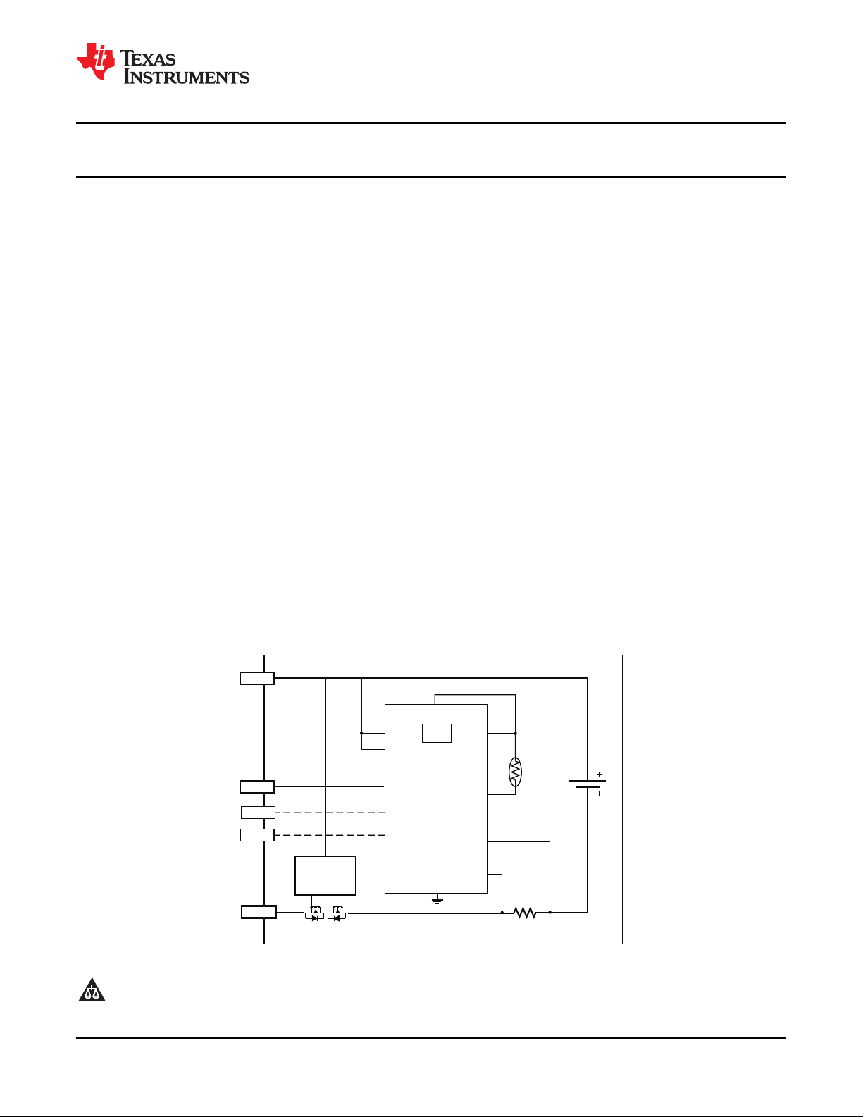
DESCRIPTION
The Texas Instruments bq27541 Li-Ion battery fuel
gauge is a microcontroller peripheral that provides
fuel gauging for single-cell Li-Ion battery packs. The
device requires little system microcontroller firmware
development for accurate battery fuel gauging. The
bq27541 resides within the battery pack or on the
system’s main-board with an embedded battery
(nonremovable).
The bq27541 uses the patented Impedance Track™
algorithm for fuel gauging, and provides information
such as remaining battery capacity (mAh),
state-of-charge (%), run-time to empty (min.), battery
voltage (mV), and temperature (°C).
The bq27541 also features integrated support for
secure battery pack authentication, using the
SHA-1/HMAC authentication algorithm.
TYPICAL APPLICATION
1
2Impedance Track is a trademark of Texas Instruments.
2
3I
C is a trademark of Phillips Corporation.
PRODUCTION DATA information is current as of publication date.
Products conform to specifications per the terms of the Texas
Instruments standard warranty. Production processing does not
necessarily include testing of all parameters.
Please be aware that an important notice concerning availability, standard warranty, and use in critical applications of Texas
Instruments semiconductor products and disclaimers thereto appears at the end of this data sheet.
Copyright © 2010, Texas Instruments Incorporated
V
SS
SRN
SRP
V
CC
HDQ
SDA
SCL
1
2
3
4
5
6
12
11
10
9
8
7
TS
REGIN
BAT
SE
REG25
bq27541-V200
bq27541-V200
SLUSA11 –FEBRUARY 2010
This integrated circuit can be damaged by ESD. Texas Instruments recommends that all integrated circuits be handled with
appropriate precautions. Failure to observe proper handling and installation procedures can cause damage.
ESD damage can range from subtle performance degradation to complete device failure. Precision integrated circuits may be more
susceptible to damage because very small parametric changes could cause the device not to meet its published specifications.
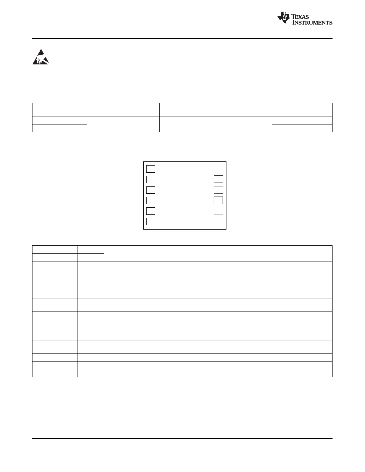
DEVICE INFORMATION
AVAILABLE OPTIONS
PRODUCTION PACKAGE TA COMMUNICATION TAPE and REEL
bq27541DRZR-V200 3000
bq27541DRZT-V200 250
(1) bq27541-V200 is shipped in I2C mode
PART #
(1)
12-pin, 2,5-mm × 4-mm SON –40°C to 85°C I2C, HDQ
FORMAT QUANTITY
(1)
bq27541PIN DIAGRAMS
(TOP VIEW)
www.ti.com
PIN FUNCTIONS
PIN DESCRIPTION
NAME NO. TYPE
BAT 4 I Cell-voltage measurement input. ADC input. Decouple with 0.1mF capacitor.
REG25 2 P 2.5V output voltage of the internal integrated LDO. Connect a minimum 0.47mF ceramic capacitor.
REGIN 3 P The input voltage for the internal integrated LDO. Connect a 0.1mF ceramic capacitor.
SCL 11 I Slave I2C serial communications clock input line for communication with system (Slave). Use with 10kΩ
SDA 10 I/O Slave I2C serial communications data line for communication with system (Slave). Open-drain I/O. Use
SE 1 O Shutdown Enable output. Push-pull output.
HDQ 12 I/O HDQ serial communications line (Slave). Open-drain.
SRN 8 IA Analog input pin connected to the internal coulomb counter where SRN is nearest the PACK- connection.
SRP 7 IA Analog input pin connected to the internal coulomb counter where SRP is nearest the CELL- connection.
TS 9 IA Pack thermistor voltage sense (use 103AT-type thermistor). ADC input
Vcc 5 P Processor power input. The minimum 0.47mF capacitor connected to REG25 should be close to Vcc.
Vss 6 P Device ground
(1) I/O = Digital input/output, IA = Analog input, P = Power connection
2 Submit Documentation Feedback Copyright © 2010, Texas Instruments Incorporated
(1)
pull-up resistor (typical).
with 10kΩ pull-up resistor (typical).
Connect to 5-mΩ to 20-mΩ sense resistor.
Connect to 5-mΩ to 20-mΩ sense resistor
Product Folder Link(s): bq27541-V200
bq27541-V200
www.ti.com
SLUSA11 –FEBRUARY 2010
ELECTRICAL SPECIFICATIONS
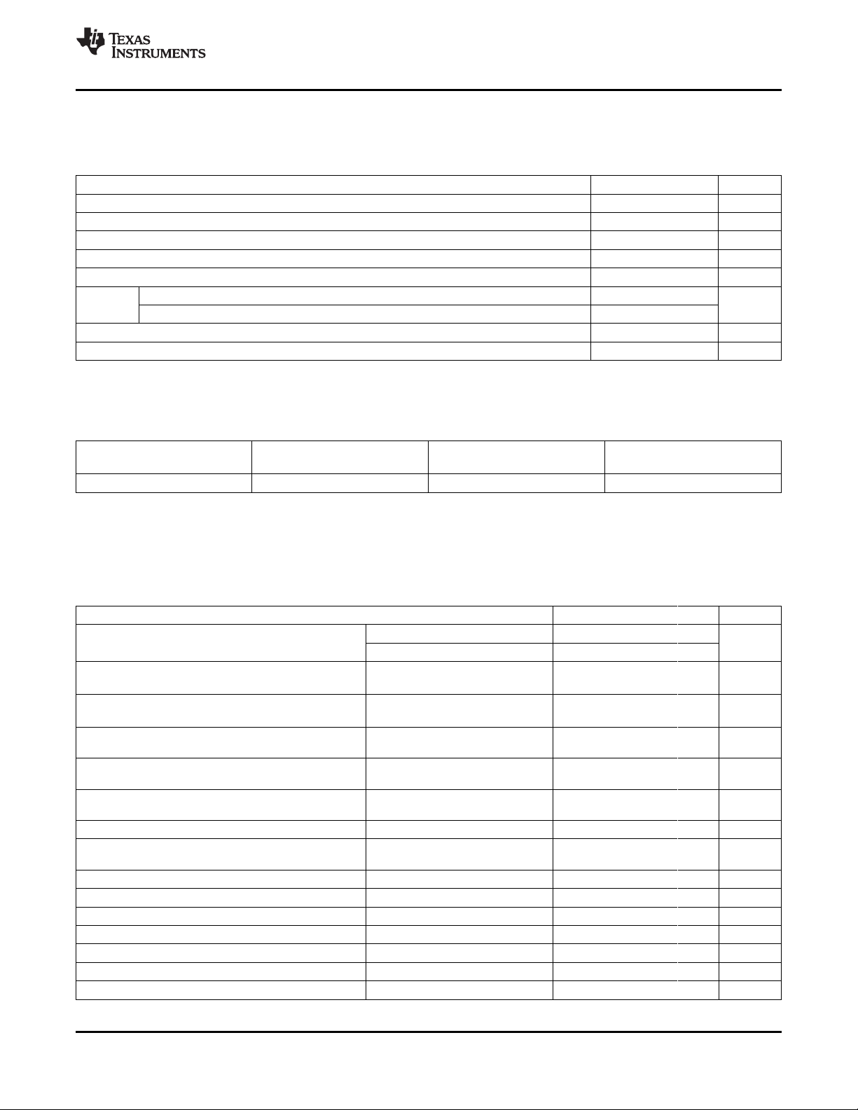
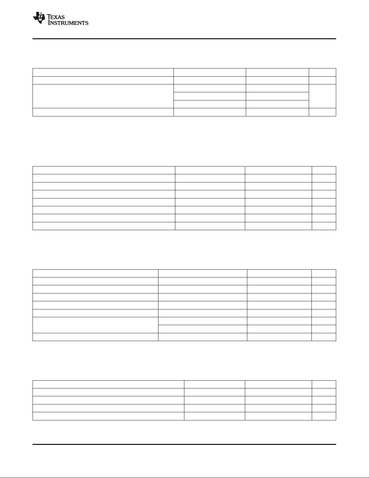
ABSOLUTE MAXIMUM RATINGS
over operating free-air temperature range (unless otherwise noted)
V
I
V
CC
V
IOD
V
BAT
V
I
ESD kV
T
F
T
stg
(1) Stresses beyond those listed under absolute maximum ratings may cause permanent damage to the device. These are stress ratings
only, and functional operation of the device at these or any other conditions beyond those indicated under recommended operating
conditions is not implied. Exposure to absolute-maximum-rated conditions for extended periods may affect device reliability.
Regulator input, REGIN –0.3 to 24 V
Supply voltage range –0.3 to 2.75 V
Open-drain I/O pins (SDA, SCL, HDQ) –0.3 to 6 V
BAT input, (pin 4) –0.3 to 6 V
Input voltage range to all others (pins 1, 7, 8, 9) –0.3 to VCC+ 0.3 V
Human Body Model (HBM), BAT pin 1.5
Human Body Model (HBM), all pins 2
Functional temperature range –40 to 100 °C
Storage temperature range –65 to 150 °C
(1)
VALUE UNIT
DISSIPATION RATINGS
PACKAGE
12-pin DRZ
(1) For the most current package and ordering information, see the Package Option Addendum at the end of this document, or see the TI
website at www.ti.com.
(2) This data is based on using a 4-layer JEDEC high-K board with the exposed die pad connected to a Cu pad on the board. The board
pad is connected to the ground plane by a 2- × 2-via matrix.
(1)
TA≤ 40°C DERATING FACTOR R
qJA
POWER RATING TA≤ 40°C
(2)
482 mW 5.67 mW/°C 176°C/W
RECOMMENDED OPERATING CONDITIONS
TA= -40°C to 85°C; typical values at TA= 25°C and V
V
I
I
CC
I
(SLP)
I
(FULLSLP)
I
(HIB)
V
OL
V
OH(PP)
V
OH(OD)
V
IL
V
IH
V
(A1)
V
(A2)
V
(A3)
I
lkg
t
PUCD
(1) Specified by design. Not tested in production.
Supply voltage, REGIN V
Normal operating mode current
(1)
Low-power operating mode current
Low-power operating mode current
Hibernate operating mode current
Output voltage low (HDQ, SDA, SCL,
SE)
Output high voltage (SE) IOH = –1 mA VCC–0.5 V
Output high voltage (HDQ, SDA, SCL) VCC–0.5 V
Input voltage low (HDQ, SDA, SCL) –0.3 0.6 V
Input voltage high (HDQ, SDA, SCL) 1.2 6 V
Input voltage range (TS) VSS–0.125 2 V
Input voltage range (BAT) VSS–0.125 5 V
Input voltage range (SRP, SRN) VSS–0.125 0.125 V
Input leakage current (I/O pins) 0.3 mA
Power-up communication delay 250 ms
(REGIN)
No operating restrictions 2.7 5.5
No FLASH writes 2.45 2.7
Fuel gauge in NORMAL mode.
I
LOAD
Fuel gauge in SLEEP mode.
(1)
I
LOAD
Fuel gauge in FULLSLEEP mode.
(1)
I
LOAD
Fuel gauge in HIBERNATE mode.
(1)
I
LOAD
IOL= 3 mA 0.4 V
External pull-up resistor connected
to Vcc
= V
= 3.6 V (unless otherwise noted)
BAT
> Sleep Current
< Sleep Current
< Sleep Current
< Hibernate Current
MIN TYP MAX UNIT
131 mA
60 mA
21 mA
6 mA
Copyright © 2010, Texas Instruments Incorporated Submit Documentation Feedback 3
Product Folder Link(s): bq27541-V200
bq27541-V200
SLUSA11 –FEBRUARY 2010
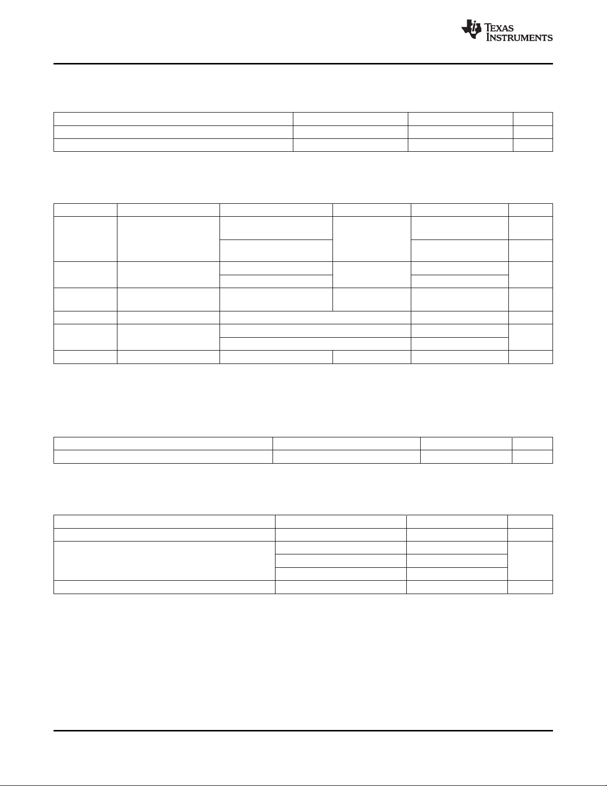
POWER-ON RESET
TA= –40°C to 85°C, C
(unless otherwise noted)
V
IT+
V
HYS
Positive-going battery voltage input at V
Power-on reset hysteresis 45 115 185 mV
2.5 V LDO REGULATOR
TA= –40°C to 85°C, C
(unless otherwise noted)
PARAMETER TEST CONDITION MIN NOM MAX UNIT
V
O
V
DO
ΔV
(REGTEMP)
ΔV
(REGLINE)
ΔV
(REGLOAD)
(2)
I
OS
(1) LDO output current, I
(2) Specified by design. Not production tested.
Regulator output voltage,
REG25
Regulator dropout voltage TA= –40°C to 85°C mV
Regulator output change
with temperature
Line regulation 2.7 V ≤ V
Load regulation mV
Short circuit current limit V
= 0.47mF, 2.45 V < V
(REG)
PARAMETER TEST CONDITIONS MIN TYP MAX UNIT
(1)
= 0.47 mF, 2.45 V < V
(REG)
, is the sum of internal and external load currents.
OUT
(REGIN)
CC
(REGIN)
2.7 V ≤ V
I
≤ 16mA
OUT
2.45 V ≤ V
battery), I
2.7 V, I
OUT
2.45 V, I
V
(REGIN)
I
= 16 mA
OUT
0.2 mA ≤ I
3 mA ≤ I
(REG25)
www.ti.com
= V
< 5.5 V; typical values at TA= 25°C and V
BAT
(REGIN)
= V
BAT
= 3.6 V
2.05 2.20 2.31 V
= V
(REGIN)
(REGIN)
OUT
BAT
≤ 5.5 V,
< 2.7 V (low
≤ 3mA
< 5.5 V; typical values at TA= 25°C and V
2.42 2.48 2.57 V
TA= –40°C to 85°C
2.4 V
(REGIN)
= V
BAT
= 3.6 V
≤ 16 mA 280
≤ 3 mA 50
OUT
= 3.6 V,
(REGIN)
OUT
≤ 16 mA, V
OUT
≤ 5.5 V, I
≤ 3 mA, V
TA= –40°C to 85°C 0.3%
= 16 mA 11 25 mV
OUT
= 2.45 V 34 40
(REGIN)
= 2.7 V 31
(REGIN)
= 0 V TA= –40°C to 85°C 250 mA
INTERNAL TEMPERATURE SENSOR CHARACTERISTICS
TA= –40°C to 85°C, C
(unless otherwise noted)
G
(TEMP)
Temperature sensor voltage gain –2.0 mV/°C
= 0.47mF, 2.45 V < V
(REG)
(REGIN)
= V
< 5.5 V; typical values at TA= 25°C and V
BAT
PARAMETER TEST CONDITIONS MIN TYP MAX UNIT
HIGH FREQUENCY OSCILLATOR
TA= –40°C to 85°C, C
(unless otherwise noted)
f
(OSC)
f
(EIO)
t
(SXO)
(1) The frequency error is measured from 2.097 MHz.
(2) The frequency drift is included and measured from the trimmed frequency at VCC= 2.5 V, TA= 25°C.
(3) The startup time is defined as the time it takes for the oscillator output frequency to be ±3%.
Operating frequency 2.097 MHz
Frequency error
Start-up time
= 0.47mF, 2.45 V < V
(REG)
(REGIN)
= V
< 5.5 V; typical values at TA= 25°C and V
BAT
PARAMETER TEST CONDITIONS MIN TYP MAX UNIT
TA= 0°C to 60°C –2.0% 0.38% 2.0%
(1) (2)
TA= –20°C to 70°C –3.0% 0.38% 3.0%
TA= –40°C to 85°C -4.5% 0.38% 4.5%
(3)
= V
= V
BAT
BAT
= 3.6 V
= 3.6 V
(REGIN)
(REGIN)
2.5 5 ms
4 Submit Documentation Feedback Copyright © 2010, Texas Instruments Incorporated
Product Folder Link(s): bq27541-V200
bq27541-V200
www.ti.com
SLUSA11 –FEBRUARY 2010
LOW FREQUENCY OSCILLATOR
TA= –40°C to 85°C, C
(unless otherwise noted)
f
(LOSC)
f
(LEIO)
t
(LSXO)
(1) The frequency drift is included and measured from the trimmed frequency at VCC= 2.5 V, TA= 25°C.
(2) The frequency error is measured from 32.768 KHz.
(3) The startup time is defined as the time it takes for the oscillator output frequency to be ±3% of typical oscillator frequency.
Operating frequency 32.768 KHz
Frequency error
Start-up time
= 0.47mF, 2.45 V < V
(REG)
(REGIN)
= V
< 5.5 V; typical values at TA= 25°C and V
BAT
(REGIN)
= V
PARAMETER TEST CONDITIONS MIN TYP MAX UNIT
TA= 0°C to 60°C –1.5% 0.25% 1.5%
(1) (2)
TA= –20°C to 70°C –2.5% 0.25% 2.5%
TA= –40°C to 85°C -4.0% 0.25% 4.0%
(3)
INTEGRATING ADC (COULOMB COUNTER) CHARACTERISTICS
TA= –40°C to 85°C, C
(unless otherwise noted)
V
IN(SR)
t
CONV(SR)
V
OS(SR)
I
NL
Z
IN(SR)
I
lkg(SR)
(1) Specified by design. Not production tested.
Input voltage range, V
Conversion time Single conversion 1 s
Resolution 14 15 bits
Input offset 10 mV
Integral nonlinearity error ±0.007 ±0.034 FSR
Effective input resistance
Input leakage current
= 0.47mF, 2.45 V < V
(REG)
(REGIN)
= V
< 5.5 V; typical values at TA= 25°C and V
BAT
(REGIN)
= V
PARAMETER TEST CONDITIONS MIN TYP MAX UNIT
(SRN)
(1)
(1)
and V
(SRP)
VSR= V
(SRN)
– V
(SRP)
–0.125 0.125 V
2.5 MΩ
= 3.6 V
BAT
500 ms
= 3.6 V
BAT
0.3 mA
ADC (TEMPERATURE AND CELL VOLTAGE) CHARACTERISTICS
TA= –40°C to 85°C, C
(unless otherwise noted)
PARAMETER TEST CONDITIONS MIN TYP MAX UNIT
V
IN(ADC)
t
CONV(ADC)
V
OS(ADC)
Z
(ADC1)
Z
(ADC2)
I
lkg(ADC)
(1) Specified by design. Not production tested.
Input voltage range –0.2 1 V
Conversion time 125 ms
Resolution 14 15 bits
Input offset 1 mV
Effective input resistance (TS)
Effective input resistance (BAT)
Input leakage current
= 0.47mF, 2.45 V < V
(REG)
(1)
= V
(REGIN)
(1)
(1)
bq27541 not measuring cell voltage 8 MΩ
< 5.5 V; typical values at TA= 25°C and V
BAT
bq27541 measuring cell voltage 100 kΩ
DATA FLASH MEMORY CHARACTERISTICS
TA= –40°C to 85°C, C
(unless otherwise noted)
t
DR
t
WORDPROG
I
CCPROG
(1) Specified by design. Not production tested.
Data retention
Flash programming write-cycles
Word programming time
Flash-write supply current
= 0.47mF, 2.45 V < V
(REG)
(REGIN)
= V
< 5.5 V; typical values at TA= 25°C and V
BAT
PARAMETER TEST CONDITIONS MIN TYP MAX UNIT
(1)
(1)
(1)
(1)
= V
(REGIN)
BAT
= 3.6 V
8 MΩ
0.3 mA
= V
(REGIN)
BAT
= 3.6 V
10 Years
20,000 Cycles
2 ms
5 10 mA
Copyright © 2010, Texas Instruments Incorporated Submit Documentation Feedback 5
Product Folder Link(s): bq27541-V200
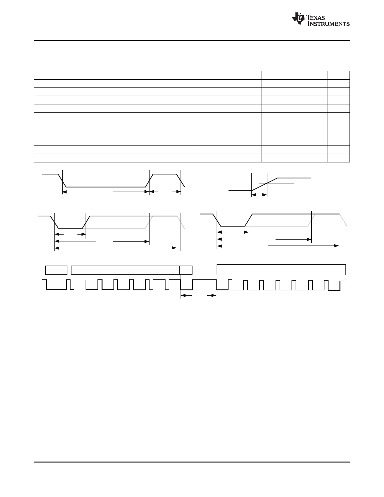
t
(B)
t
(BR)
t
(HW1)
t
(HW0)
t
(CYCH)
t
(DW1)
t
(DW0)
t
(CYCD)
Break
7-bitaddress
8-bitdata
(a) BreakandBreakRecovery
(c) Host TransmittedBit
(d) Gauge TransmittedBit
(e) GaugetoHostResponse
1.2V
t
(RISE)
(b) HDQlinerisetime
1-bit
R/W
t
(RSPS)
bq27541-V200
SLUSA11 –FEBRUARY 2010
HDQ COMMUNICATION TIMING CHARACTERISTICS
TA= –40°C to 85°C, C
(unless otherwise noted)
t
(CYCH)
t
(CYCD)
t
(HW1)
t
(DW1)
t
(HW0)
t
(DW0)
t
(RSPS)
t
(B)
t
(BR)
t
(RISE)
= 0.47mF, 2.45 V < V
REG
REGIN
= V
< 5.5 V; typical values at TA= 25°C and V
BAT
PARAMETER TEST CONDITIONS MIN TYP MAX UNIT
Cycle time, host to bq27541 190 ms
Cycle time, bq27541 to host 190 205 250 ms
Host sends 1 to bq27541 0.5 50 ms
bq27541 sends 1 to host 32 50 ms
Host sends 0 to bq27541 86 145 ms
bq27541 sends 0 to host 80 145 ms
Response time, bq27541 to host 190 320 ms
Break time 190 ms
Break recovery time 40 ms
HDQ line resing time to logic 1 (1.2V) 950 ns
REGIN
= V
BAT
www.ti.com
= 3.6 V
Figure 1. Timing Diagrams
6 Submit Documentation Feedback Copyright © 2010, Texas Instruments Incorporated
Product Folder Link(s): bq27541-V200
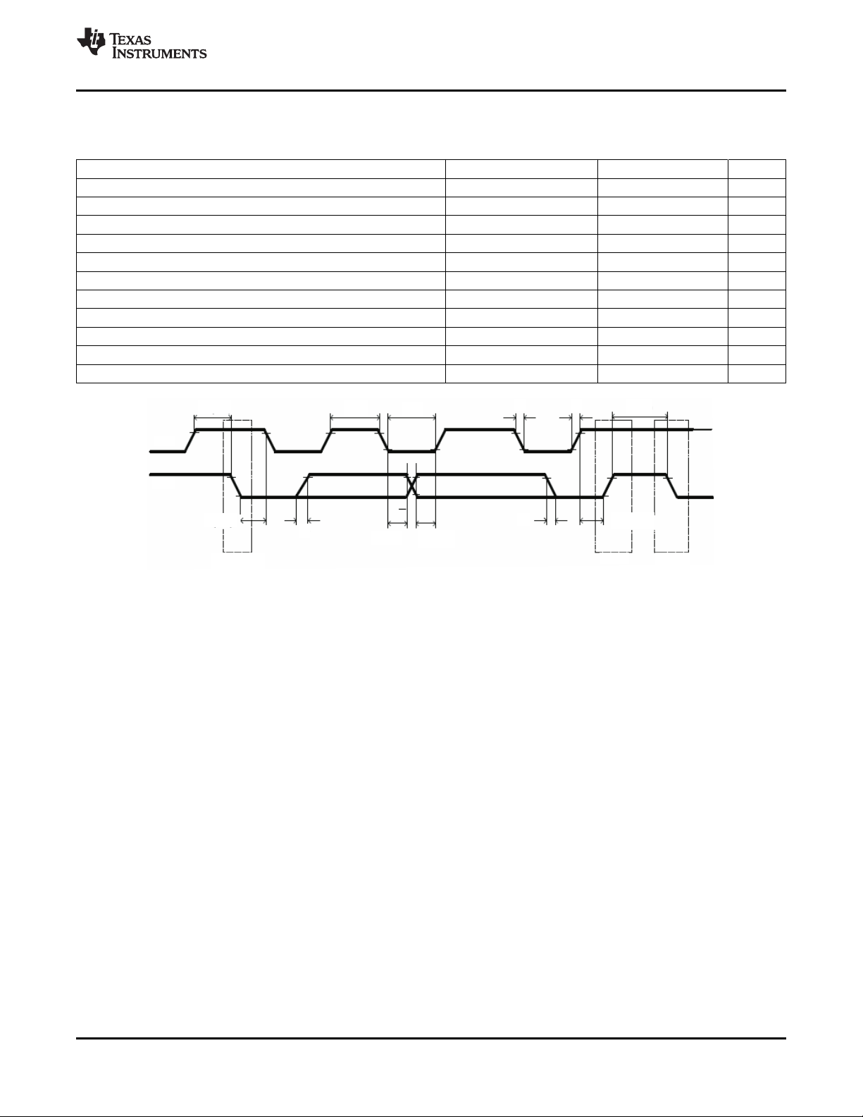
t
SU(STA)
SCL
SDA
t
w(H)
t
w(L)
t
f
t
r
t
(BUF)
t
r
t
d(STA)
REPEATED
START
t
h(DAT)tsu(DAT)
t
f
t
su(STOP)
STOP START
bq27541-V200
www.ti.com
I2C-COMPATIBLE INTERFACE TIMING CHARACTERISTICS
TA= –40°C to 85°C, C
(unless otherwise noted)
t
r
t
f
t
w(H)
t
w(L)
t
su(STA)
t
d(STA)
t
su(DAT)
t
h(DAT)
t
su(STOP)
t
BUF
f
SCL
SCL/SDA rise time 300 ns
SCL/SDA fall time 300 ns
SCL pulse width (high) 600 ns
SCL pulse width (low) 1.3 ms
Setup for repeated start 600 ns
Start to first falling edge of SCL 600 ns
Data setup time 1000 ns
Data hold time 0 ns
Setup time for stop 600 ns
Bus free time between stop and start 66 ms
Clock frequency 400 kHz
= 0.47mF, 2.45 V < V
REG
REGIN
= V
< 5.5 V; typical values at TA= 25°C and V
BAT
PARAMETER TEST CONDITIONS MIN TYP MAX UNIT
SLUSA11 –FEBRUARY 2010
= V
REGIN
BAT
= 3.6 V
Figure 2. I2C-Compatible Interface Timing Diagrams
GENERAL DESCRIPTION
The bq27541 accurately predicts the battery capacity and other operational characteristics of a single Li-based
rechargeable cell. It can be interrogated by a system processor to provide cell information, such as
state-of-charge (SOC), time-to-empty (TTE) and time-to-full (TTF).
Information is accessed through a series of commands, called Standard Commands. Further capabilities are
provided by the additional Extended Commands set. Both sets of commands, indicated by the general format
Command( ), are used to read and write information contained within the bq27541 control and status registers,
as well as its data flash locations. Commands are sent from system to gauge using the bq27541’s serial
communications engine, and can be executed during application development, pack manufacture, or
end-equipment operation.
Cell information is stored in the bq27541 in non-volatile flash memory. Many of these data flash locations are
accessible during application development. They cannot, generally, be accessed directly during end-equipment
operation. Access to these locations is achieved by either use of the bq27541’s companion evaluation software,
through individual commands, or through a sequence of data-flash-access commands. To access a desired data
flash location, the correct data flash subclass and offset must be known
The bq27541 provides 96 bytes of user-programmable data flash memory, partitioned into three (3) 32-byte
blocks: Manufacturer Info Block A, Manufacturer Info Block B, and Manufacturer Info Block C. This data
space is accessed through a data flash interface. For specifics on accessing the data flash, see section
Manufacturer Information Blocks. The key to the bq27541’s high-accuracy gas gauging prediction is Texas
Instrument’s proprietary Impedance Track™ algorithm. This algorithm uses cell measurements, characteristics,
and properties to create state-of-charge predictions that can achieve less than 1% error across a wide variety of
operating conditions and over the lifetime of the battery.
Copyright © 2010, Texas Instruments Incorporated Submit Documentation Feedback 7
Product Folder Link(s): bq27541-V200

bq27541-V200
SLUSA11 –FEBRUARY 2010
www.ti.com
The bq27541 measures charge/discharge activity by monitoring the voltage across a small-value series sense
resistor (5 mΩ to 20 mΩ typ.) located between the CELL-and the battery’s PACK-terminal. When a cell is
attached to the bq27541, cell impedance is computed, based on cell current, cell open-circuit voltage (OCV), and
cell voltage under loading conditions.
The bq27541 external temperature sensing is optimized with the use of a high accuracy negative temperature
coefficient (NTC) thermistor with R25 = 10kΩ ± 1% and B25/85 = 3435kΩ ± 1% (such as Semitec 103AT for
measurement). The bq2741 can also be configured to use its internal temperature sensor. The bq27541 uses
temperature to monitor the battery-pack environment, which is used for fuel gauging and cell protection
functionality.
To minimize power consumption, the bq27541 has different power modes: NORMAL, SLEEP, FULLSLEEP,
HIBERNATE, and PRESHUTDOWN. The bq27541 passes automatically between these modes, depending upon
the occurrence of specific events, though a system processor can initiate some of these modes directly. More
details can be found in section Power Modes.
NOTE
FORMATTING CONVENTIONS IN THIS DOCUMENT:
Commands: italics with parentheses( ) and no breaking spaces. e.g. RemainingCapacity( )
Data Flash: italics, bold, and breaking spaces. e.g. Design Capacity
Register bits and flags: italics with brackets[]. e.g. [TDA]
Data flash bits: italics, bold, and brackets[]. e.g: [LED1]
Modes and states: ALL CAPITALS. e.g. UNSEALED mode
do not delete this subsection
8 Submit Documentation Feedback Copyright © 2010, Texas Instruments Incorporated
Product Folder Link(s): bq27541-V200

bq27541-V200
www.ti.com
SLUSA11 –FEBRUARY 2010
DATA COMMANDS
STANDARD DATA COMMANDS
The bq27541 uses a series of 2-byte standard commands to enable system reading and writing of battery
information. Each standard command has an associated command-code pair, as indicated in Table 1. Each
protocol has specific means to access the data at each Command Code. DataRAM is updated and read by the
gauge only once per second. Standard commands are accessible in NORMAL operation mode.
Table 1. Standard Commands
NAME COMMAND CODE UNITS SEALED
Control( ) CNTL 0x00 / 0x01 N/A R/W
AtRate( ) AR 0x02 / 0x03 mA R/W
AtRateTimeToEmpty( ) ARTTE 0x04 / 0x05 Minutes R
Temperature( ) TEMP 0x06 / 0x07 0.1K R
Voltage( ) VOLT 0x08 / 0x09 mV R
Flags( ) FLAGS 0x0a / 0x0b N/A R
NominalAvailableCapacity( ) NAC 0x0c / 0x0d mAh R
FullAvailableCapacity( ) FAC 0x0e / 0x0f mAh R
RemainingCapacity( ) RM 0x10 / 0x11 mAh R
FullChargeCapacity( ) FCC 0x12 / 0x13 mAh R
AverageCurrent( ) AI 0x14 / 0x15 mA R
TimeToEmpty( ) TTE 0x16 / 0x17 Minutes R
TimeToFull( ) TTF 0x18 / 0x19 Minutes R
StandbyCurrent( ) SI 0x1a / 0x1b mA R
StandbyTimeToEmpty( ) STTE 0x1c / 0x1d Minutes R
MaxLoadCurrent( ) MLI 0x1e / 0x1f mA R
MaxLoadTimeToEmpty( ) MLTTE 0x20 / 0x21 Minutes R
AvailableEnergy( ) AE 0x22 / 0x23 10 mWhr R
AveragePower( ) AP 0x24 / 0x25 10 mW R
TTEatConstantPower( ) TTECP 0x26 / 0x27 Minutes R
Internal_Temp( ) INTTEMP 0x28 / 0x29 0.1°K R
CycleCount( ) CC 0x2a / 0x2b Counts R
StateOfCharge( ) SOC 0x2c / 0x2d % R
StateOfHealth( ) SOH 0x2e / 0x2f % / num R
PassedCharge( ) PCHG 0x34 / 0x35 mAh R
DOD0( ) DOD0 0x36 / 0x37 HEX# R
ACCESS
Copyright © 2010, Texas Instruments Incorporated Submit Documentation Feedback 9
Product Folder Link(s): bq27541-V200

bq27541-V200
SLUSA11 –FEBRUARY 2010
www.ti.com
Control( ): 0x00/0x01
Issuing a Control( ) command requires a subsequent 2-byte subcommand. These additional bytes specify the
particular control function desired. The Control( ) command allows the system to control specific features of the
bq27541 during normal operation and additional features when the bq27541 is in different access modes, as
described in Table 2.
Table 2. Control( ) Subcommands
CNTL FUNCTION CNTL DATA SEALED DESCRIPTION
CONTROL_STATUS 0x0000 Yes Reports the status of DF Checksum, Hibernate, IT, etc.
DEVICE_TYPE 0x0001 Yes Reports the device type of 0x0541 (indicating bq27541)
FW_VERSION 0x0002 Yes Reports the firmware version on the device type
HW_VERSION 0x0003 Yes Reports the hardware version of the device type
DF_CHECKSUM 0x0004 No Enables a data flash checksum to be generated and reports on a read
RESET_DATA 0x0005 No Returns reset data
Reserved 0x0006 No Not to be used
PREV_MACWRITE 0x0007 No Returns previous MAC command code
CHEM_ID 0x0008 Yes Reports the chemical identifier of the Impedance Track™ configuration
DF_VERSION 0x000C Yes Reports the data flash version on the device
SET_FULLSLEEP 0x0010 No Set the [FullSleep] bit in Control Status register to 1
SET_HIBERNATE 0x0011 Yes Forces CONTROL_STATUS [HIBERNATE] to 1
CLEAR_HIBERNATE 0x0012 Yes Forces CONTROL_STATUS [HIBERNATE] to 0
SET_SHUTDOWN 0x0013 Yes Enables the SE pin to change state
CLEAR_SHUTDOWN 0x0014 Yes Disables the SE pin from changing state
SET_HDQINTEN 0x0015 Yes Forces CONTROL_STATUS [HDQIntEn] to 1
CLEAR_HDQINTEN 0x0016 Yes Forces CONTROL_STATUS [HDQIntEn] to 0
SEALED 0x0020 No Places the bq27541 is SEALED access mode
IT_ENABLE 0x0021 No Enables the Impedance Track™ algorithm
CAL_MODE 0x0040 No Places the bq27541 in calibration mode
RESET 0x0041 No Forces a full reset of the bq27541
ACCESS
10 Submit Documentation Feedback Copyright © 2010, Texas Instruments Incorporated
Product Folder Link(s): bq27541-V200

bq27541-V200
www.ti.com
SLUSA11 –FEBRUARY 2010
CONTROL_STATUS: 0X0000
Instructs the fuel gauge to return status information to Control addresses 0x00/0x01. The status word includes
the following information.
Table 3. CONTROL_STATUS Flags
bit7 bit6 bit5 bit4 bit3 bit2 bit1 bit0
High Byte SE FAS SS CSV CCA BCA – HDAIntEn
Low Byte SHUTDOWN HIBERNATE FULLSLEEP SLEEP LDMD RUP_DIS VOK QEN
SE = Status bit indicating the SE pin is active. True when set. Default is 0.
FAS = Status bit indicating the bq27541 is in FULL ACCESS SEALED state. Active when set.
SS = Status bit indicating the bq27541 is in the SEALED State. Active when set.
CSV = Status bit indicating a valid data flash checksum has been generated. Active when set.
CCA = Status bit indicating the bq27541 Coulomb Counter Calibration routine is active. Active when set.
BCA = Status bit indicating the bq27541 Board Calibration routine is active. Active when set.
HDQIntEn = Status bit indicating the HDQ interrupt function is active. True when set. Default is 0.
SHUTDOWN = Control bit indicating the fuel gauge can force its SE pin low to signal an external shutdown. True when set. Default is 0.
HIBERNATE = Status bit indicating a request for entry into HIBERNATE from SLEEP mode has been issued. True when set. Default is
FULLSLEEP =
SLEEP = Status bit indicating the bq27541 is in SLEEP mode. True when set
LDMD = Status bit indicating the bq27541 Impedance Track™ algorithm using constant-power mode. True when set. Default is 0
RUP_DIS = Status bit indicating the bq27541 Ra table updates are disabled. True when set.
VOK = Status bit indicating cell voltages are OK for Qmax updates. True when set.
QEN = Status bit indicating the bq27541 Qmax updates are enabled. True when set.
0. Control bit when set will put the bq27541 into the lower power state of SLEEP mode. It is not possible to monitor this
bit
Status bit indicating the bq27541 is in FULLSLEEP mode. True when set. The state can be detected by monitoring the
power used by the bq27541 because any communication will automatically clear it
(constant-current mode).
Copyright © 2010, Texas Instruments Incorporated Submit Documentation Feedback 11
Product Folder Link(s): bq27541-V200

bq27541-V200
SLUSA11 –FEBRUARY 2010
www.ti.com
DEVICE_TYPE: 0X0001
Instructs the fuel gauge to return the device type to addresses 0x00/0x01.
FW_VERSION: 0X0002
Instructs the fuel gauge to return the firmware version to addresses 0x00/0x01.
HW_VERSION: 0X0003
Instructs the fuel gauge to return the hardware version to addresses 0x00/0x01.
DF_CHECKSUM: 0X0004
Instructs the fuel gauge to compute the checksum of the data flash memory. The checksum value is written and
returned to addresses 0x00/0x01 (UNSEALED mode only). The checksum will not be calculated in SEALED
mode; however, the checksum value can still be read.
RESET_DATA: 0X0005
Instructs the fuel gauge to return the reset data to addresses 0x00/0x01.
PREV_MACWRITE: 0X0007
Instructs the fuel gauge to return the previous command written to addresses 0x00/0x01. The value returned is
limited to less than 0x0020.
CHEM_ID: 0X0008
Instructs the fuel gauge to return the chemical identifier for the Impedance Track™ configuration to addresses
0x00/0x01.
DF_VERSION: 0x000C
Instructs the gas gauge to return the data flash version to addresses 0x00/0x01
SET_FULLSLEEP: 0X0010
Instructs the gas gauge to set the FullSleep bit in Control Status register to 1. This will allow the gauge to enter
the FULLSLEEP power mode after the transition to SLEEP power state is detected. In FullSleep mode less
power is consumed by disabling an oscillator circuit used by the communication engines. For HDQ
communication one host message will be dropped. For I2C communications the first I2C message will incur a
6–8 millisecond clock stretch while the oscillator is started and stabilized. A communication to the device in
FULLSLEEP will force the part back to the SLEEP mode.
SET_HIBERNATE: 0X0011
Instructs the fuel gauge to force the CONTROL_STATUS [HIBERNATE] bit to 1. This will allow the gauge to
enter the HIBERNATE power mode after the transition to SLEEP power state is detected. The [HIBERNATE] bit
is automatically cleared upon exiting from HIBERNATE mode.
CLEAR_HIBERNATE: 0X0012
Instructs the fuel gauge to force the CONTROL_STATUS [HIBERNATE] bit to 0. This will prevent the gauge from
entering the HIBERNATE power mode after the transition to SLEEP power state is detected. It can also be used
to force the gauge out of HIBERNATE mode.
SET_SHUTDOWN: 0x0013
Sets the CONTROL_STATUS [SHUTDOWN] bit to 1, thereby enabling the SE pin to change state. The
Impedance Track algorithm controls the setting of the SE pin, depending on whether the conditions are met for
fuel gauge shutdown or not.
12 Submit Documentation Feedback Copyright © 2010, Texas Instruments Incorporated
Product Folder Link(s): bq27541-V200

bq27541-V200
www.ti.com
SLUSA11 –FEBRUARY 2010
CLEAR_SHUTDOWN: 0X0014
Disables the SE pin from changing state. The SE pin is left in a high-impedance state.
SET_HDQINTEN: 0x0015
Instructs the fuel gauge to set the CONTROL_STATUS [HDQIntEn] bit to 1. This will enable the HDQ Interrupt
function. When the this subcommand is received, the bq27541 will detect any of the interrupt conditions and
assert the interrupt at one second intervals until the CLEAR_HDQINTEN command is received or the count of
HDQHostIntrTries has lapsed.
CLEAR_HDQINTEN: 0x0016
Instructs the fuel gauge to set the CONTROL_STATUS [HDQIntEn] bit to 0. This will disable the HDQ Interrupt
function.
SEALED: 0X0020
Instructs the gas gauge to transition from UNSEALED state to SEALED state. The gas gauge should always be
set to SEALED state for use in customer’s end equipment.
IT ENABLE: 0X0021
This command forces the fuel gauge to begin the Impedance Track™ algorithm, sets the active
UpdateStatuslocation to 0x01 and causes the [VOK] and [QEN] flags to be set in the CONTROL_STATUS
register. [VOK] is cleared if the voltages are not suitable for a Qmax update. Once set, [QEN] cannot be cleared.
This command is only available when the fuel gauge is UNSEALED.
CAL MODE: 0X0040
This command instructs the gas gauge to enter calibration mode. This command is only available when the gas
gauge is UNSEALED.
RESET: 0X0041
This command instructs the gas gauge to perform a full reset. This command is only available when the gas
gauge is UNSEALED.
AtRate( ): 0x02/0x03
The AtRate( ) read-/write-word function is the first half of a two-function command call-set used to set the AtRate
value used in calculations made by the AtRateTimeToEmpty( ) function. The AtRate( ) units are in mA.
The AtRate( ) value is a signed integer, with negative values interpreted as a discharge current value. The
AtRateTimeToEmpty( ) function returns the predicted operating time at the AtRate value of discharge. The
default value for AtRate( ) is zero and will force AtRateTimeToEmpty( ) to return 65,535. Both the AtRate( ) and
AtRateTimeToEmpty( ) commands should only be used in NORMAL mode.
AtRateTimeToEmpty( ): 0x04/0x05
This read-only function returns an unsigned integer value of the predicted remaining operating time if the battery
is discharged at the AtRate( ) value in minutes with a range of 0 to 65,534. A value of 65,535 indicates AtRate( )
= 0. The fuel gauge updates AtRateTimeToEmpty( ) within 1 s after the system sets the AtRate( ) value. The fuel
gauge automatically updates AtRateTimeToEmpty( ) based on the AtRate( ) value every 1s. Both the AtRate( )
and AtRateTimeToEmpty( ) commands should only be used in NORMAL mode.
Temperature( ): 0x06/0x07
This read-only function returns an unsigned integer value of the battery temperature in units of 0.1K measured by
the fuel gauge.
Voltage( ): 0x08/0x09
This read-only function returns an unsigned integer value of the measured cell-pack voltage in mV with a range
of 0 to 6000 mV.
Copyright © 2010, Texas Instruments Incorporated Submit Documentation Feedback 13
Product Folder Link(s): bq27541-V200

bq27541-V200
SLUSA11 –FEBRUARY 2010
www.ti.com
Flags( ): 0x0a/0x0b
This read-only function returns the contents of the gas-gauge status register, depicting the current operating
status.
Table 4. Flags Bit Definitions
bit7 bit6 bit5 bit4 bit3 bit2 bit1 bit0
High Byte OTC OTD – – CHG_INH XCHG FC CHG
Low Byte OCVTAKEN – – – – SOC1 SOCF DSG
OTC = Over-Temperature in Charge condition is detected. True when set.
OTD = Over-Temperature in Discharge condition is detected. True when set.
CHG_INH = Charge Inhibit indicates the temperature is outside the range [Charge Inhibit Temp Low, Charge Inhibit Temp
XCHG = Charge Suspend Alert indicates the temperature is outside the range [Suspend Temperature Low, Suspend
CHG = (Fast) charging allowed. True when set.
OVERTAKEN = Cleared on entry to relax mode and set to 1 when OCV measurement is performed in relax
SOC1 = State-of-Charge-Threshold 1 (SOC1 Set) reached. True when set.
SOCF = State-of-Charge-Threshold Final (SOCF Set %) reached. True when set.
DSG = Discharging detected. True when set.
High]. True when set.
Temperature High].
FC = Full-charged condition reached (RMFCC=1; Set FC_Set%=-1% when RMFCC=0). True when set
NominalAvailableCapacity( ): 0x0c/0x0d
This read-only command pair returns the uncompensated (less than C/20 load) battery capacity remaining. Units
are mAh.
FullAvailableCapacity( ): 0x0e/0x0f
This read-only command pair returns the uncompensated (less than C/20 load) capacity of the battery when fully
charged. Units are mAh. FullAvailableCapacity( ) is updated at regular intervals, as specified by the IT algorithm.
RemainingCapacity( ): 0x10/0x11
This read-only command pair returns the compensated battery capacity remaining. Units are mAh.
FullChargeCapacity( ): 0x12/13
This read-only command pair returns the compensated capacity of the battery when fully charged. Units are
mAh. FullChargeCapacity( ) is updated at regular intervals, as specified by the IT algorithm.
AverageCurrent( ): 0x14/0x15
This read-only command pair returns a signed integer value that is the average current flow through the sense
resistor. It is updated every 1 second. Units are mA.
TimeToEmpty( ): 0x16/0x17
This read-only function returns an unsigned integer value of the predicted remaining battery life at the present
rate of discharge, in minutes. A value of 65,535 indicates battery is not being discharged.
TimeToFull( ): 0x18/0x19
This read-only function returns an unsigned integer value of predicted remaining time until the battery reaches
full charge, in minutes, based upon AverageCurrent( ). The computation accounts for the taper current time
extension from the linear TTF computation based on a fixed AverageCurrent( ) rate of charge accumulation. A
value of 65,535 indicates the battery is not being charged.
14 Submit Documentation Feedback Copyright © 2010, Texas Instruments Incorporated
Product Folder Link(s): bq27541-V200

bq27541-V200
www.ti.com
SLUSA11 –FEBRUARY 2010
StandbyCurrent( ): 0x1a/0x1b
This read-only function returns a signed integer value of the measured standby current through the sense
resistor. The StandbyCurrent( ) is an adaptive measurement. Initially it reports the standby current programmed
in Initial Standby, and after spending some time in standby, reports the measured standby current.
The register value is updated every 1 second when the measured current is above the Deadband and is less
than or equal to 2 x Initial Standby. The first and last values that meet this criteria are not averaged in, since
they may not be stable values. To approximate a 1 minute time constant, each new StandbyCurrent( ) value is
computed by taking approximate 93% weight of the last standby current and approximate 7% of the current
measured average current.
StandbyTimeToEmpty( ): 0x1c/0x1d
This read-only function returns an unsigned integer value of the predicted remaining battery life at the standby
rate of discharge, in minutes. The computation uses Nominal Available Capacity (NAC), the uncompensated
remaining capacity, for this computation. A value of 65,535 indicates battery is not being discharged.
MaxLoadCurrent( ): 0x1e/0x1f
This read-only function returns a signed integer value, in units of mA, of the maximum load conditions. The
MaxLoadCurrent( ) is an adaptive measurement which is initially reported as the maximum load current
programmed in Initial Max Load Current. If the measured current is ever greater than Initial Max Load
Current, then MaxLoadCurrent( ) updates to the new current. MaxLoadCurrent( ) is reduced to the average of
the previous value and Initial Max Load Current whenever the battery is charged to full after a previous
discharge to an SOC less than 50%. This prevents the reported value from maintaining an unusually high value.
MaxLoadTimeToEmpty( ): 0x20/0x21
This read-only function returns an unsigned integer value of the predicted remaining battery life at the maximum
load current discharge rate, in minutes. A value of 65,535 indicates that the battery is not being discharged.
AvailableEnergy( ): 0x22/0x23
This read-only function returns an unsigned integer value of the predicted charge or energy remaining in the
battery. The value is reported in units of mWh.
AveragePower( ): 0x24/0x25
This read-word function returns an unsigned integer value of the average power of the current discharge. It is
negative during discharge and positive during charge. A value of 0 indicates that the battery is not being
discharged. The value is reported in units of mW.
TimeToEmptyAtConstantPower( ): 0x26/0x27
This read-only function returns an unsigned integer value of the predicted remaining operating time if the battery
is discharged at the AveragePower( ) value in minutes. A value of 65,535 indicates AveragePower( ) = 0. The
fuel gauge automatically updates TimeToEmptyatContantPower( ) based on the AveragePower( ) value every 1s.
Internal_Temp( ): 0x28/0x29
This read-only function returns an unsigned integer value of the measured internal temperature of the device in
units of 0.1K measured by the fuel gauge.
CycleCount( ): 0x2a/0x2b
This read-only function returns an unsigned integer value of the number of cycles the battery has experienced
with a range of 0 to 65,535. One cycle occurs when accumulated discharge ≥ CC Threshold.
StateOfCharge( ): 0x2c/0x2d
This read-only function returns an unsigned integer value of the predicted remaining battery capacity expressed
as a percentage of FullChargeCapacity( ), with a range of 0 to 100%.
Copyright © 2010, Texas Instruments Incorporated Submit Documentation Feedback 15
Product Folder Link(s): bq27541-V200

bq27541-V200
SLUSA11 –FEBRUARY 2010
www.ti.com
StateOfHealth( ): 0x2e/0x2f
0x2e SOH percentage: this read-only function returns an unsigned integer value, expressed as a percentage of
the ration of predicted FCC(25°C, SOH current rate) over the DesignCapacity(). The FCC(25°C, SOH current
rate) is the calculated full charge capacity at 25°C and the SOH current rate which is specified in the data flash
(State of Health Load I). The range of the returned SOH percentage is 0x00 to 0x64, indicating 0 to 100%
correspondingly.
0x2f SOH Status: this read-only function returns an unsigned integer value, indicating the status of the SOH
percentage. The meanings of the returned value are:
• 0x00: SOH not valid (initialization)
• 0x01: Instant SOH value ready
• 0x02: Initial SOH value ready
– Calculation based on uncompensated Qmax
– Updated at first grid point update after cell insertion
• 0x03: SOH value ready
– Utilize the updated Qmax update
– Calculation based on compensated Qmax
– Updated after complete charge and relax is complete
• 0x04-0xFF: Reserved
PassedCharge( ): 0x34/0x35
This signed integer indicates the amount of charge passed through the sense resistor since the last IT simulation
in mAh.
DOD0( ): 0x36/0x37
This unsigned integer indicates the depth of discharge during the most recent OCV reading.
16 Submit Documentation Feedback Copyright © 2010, Texas Instruments Incorporated
Product Folder Link(s): bq27541-V200

bq27541-V200
www.ti.com
SLUSA11 –FEBRUARY 2010
EXTENDED DATA COMMANDS
Extended commands offer additional functionality beyond the standard set of commands. They are used in the
same manner; however unlike standard commands, extended commands are not limited to 2-byte words. The
number of commands bytes for a given extended command ranges in size from single to multiple bytes, as
specified in Table 5. For details on the SEALED and UNSEALED states, see Section Access Modes.
Table 5. Extended Commands
NAME COMMAND CODE UNITS SEALED UNSEALED
ACCESS
Reserved RSVD 0x38…0x39 N/A R R
PackConfig( ) PCR 0x3a / 0x3b HEX# R R
DesignCapacity( ) DCAP 0x3c / 0x3d mAh R R
DataFlashClass( )
DataFlashBlock( )
BlockData( ) / Authenticate( )
BlockData( ) / AuthenticateCheckSum( )
BlockData( ) DFD 0x55…0x5f N/A R R/W
BlockDataCheckSum( ) DFDCKS 0x60 N/A R/W R/W
BlockDataControl( ) DFDCNTL 0x61 N/A N/A R/W
DeviceNameLength( ) DNAMELEN 0x62 N/A R R
DeviceName( ) DNAME 0x63...0x69 N/A R R
Reserved RSVD 0x6a...0x7f N/A R R
(1) SEALED and UNSEALED states are entered via commands to Control( ) 0x00/0x01
(2) In SEALED mode, data flash CANNOT be accessed through commands 0x3e and 0x3f.
(3) The BlockData( ) command area shares functionality for accessing general data flash and for using Authentication. See section on
Authentication for more details.
(2)
(2)
(3)
(3)
DFCLS 0x3e N/A N/A R/W
DFBLK 0x3f N/A R/W R/W
A/DF 0x40…0x53 N/A R/W R/W
ACKS/DFD 0x54 N/A R/W R/W
(1) (2)
ACCESS
(1) (2)
PackConfig( ): 0x3a/0x3b
SEALED and UNSEALED Access: This command returns the value is stored in Pack Configuration and is
expressed in hex value.
DesignCapacity( ): 0x3c/0x3d
SEALED and UNSEALED Access: This command returns the value is stored in Design Capacity and is
expressed in mAh. This is intended to be the theoretical or nominal capacity of a new pack, but has no bearing
on the operation of the fuel gauge functionality.
DataFlashClass( ): 0x3e
This command sets the data flash class to be accessed. The class to be accessed should be entered in
hexadecimal.
SEALED Access: This command is not available in SEALED mode.
DataFlashBlock( ): 0x3f
UNSEALED Access: This command sets the data flash block to be accessed. When 0x00 is written to
BlockDataControl( ), DataFlashBlock( ) holds the block number of the data flash to be read or written. Example:
writing a 0x00 to DataFlashBlock( ) specifies access to the first 32 byte block and a 0x01 specifies access to the
second 32 byte block, and so on.
SEALED Access: This command directs which data flash block will be accessed by the BlockData( ) command.
Writing a 0x00 to DataFlashBlock( ) specifies the BlockData( ) command will transfer authentication data. Issuing
a 0x01, 0x02 or 0x03 instructs the BlockData( ) command to transfer Manufacturer Info Block A, B, or C,
respectively.
Copyright © 2010, Texas Instruments Incorporated Submit Documentation Feedback 17
Product Folder Link(s): bq27541-V200

bq27541-V200
SLUSA11 –FEBRUARY 2010
www.ti.com
BlockData( ): 0x40…0x5f
This command range is used to transfer data for data flash class access. This command range is the 32-byte
data block used to access Manufacturer Info Block A, B, or C. Manufacturer Info Block A is read only for the
sealed access. UNSEALED access is read/write.
BlockDataChecksum( ): 0x60
The host system should write this value to inform the device that new data is ready for programming into the
specified data flash class and block.”
UNSEALED Access: This byte contains the checksum on the 32 bytes of block data read or written to data flash.
The least-significant byte of the sum of the data bytes written must be complemented ( [255 – x] , for x the
least-significant byte) before being written to 0x60.
SEALED Access: This byte contains the checksum for the 32 bytes of block data written to Manufacturer Info
Block A, B, or C. The least-significant byte of the sum of the data bytes written must be complemented ( [255 –
x] , for x the least-significant byte) before being written to 0x60.
BlockDataControl( ): 0x61
UNSEALED Access: This command is used to control data flash access mode. Writing 0x00 to this command
enables BlockData( ) to access general data flash. Writing a 0x01 to this command enables SEALED mode
operation of DataFlashBlock( ).
SEALED Access: This command is not available in SEALED mode.
DeviceNameLength( ): 0x62
UNSEALED and SEALED Access: This byte contains the length of the Device Name.
DeviceName( ): 0x63…0x69
UNSEALED and SEALED Access: This block contains the device name that is programmed in Device Name.
Reserved – 0x6a – 0x7f
SERIAL NUMBER
The bq27541 serial number can be read in the unsealed mode with authentication data flash control and data
flash block commands. The operation under unsealed mode is as the following steps:
1. write 0x02 to register 0x61
2. write 0x00 to register 0x3f
3. read the 8 byte serial number from registers 0x40 to 0x47
do not delete this para
DATA FLASH INTERFACE
ACCESSING THE DATA FLASH
The bq27541 data flash is a non-volatile memory that contains bq27541 initialization, default, cell status,
calibration, configuration, and user information. The data flash can be accessed in several different ways,
depending on what mode the bq27541 is operating in and what data is being accessed.
Commonly accessed data flash memory locations, frequently read by a system, are conveniently accessed
through specific instructions, already described in Section Data Commands. These commands are available
when the bq27541 is either in UNSEALED or SEALED modes.
18 Submit Documentation Feedback Copyright © 2010, Texas Instruments Incorporated
Product Folder Link(s): bq27541-V200

bq27541-V200
www.ti.com
SLUSA11 –FEBRUARY 2010
Most data flash locations, however, are only accessible in UNSEALED mode by use of the bq27541 evaluation
software or by data flash block transfers. These locations should be optimized and/or fixed during the
development and manufacture processes. They become part of a golden image file and can then be written to
multiple battery packs. Once established, the values generally remain unchanged during end-equipment
operation.
To access data flash locations individually, the block containing the desired data flash location(s) must be
transferred to the command register locations, where they can be read to the system or changed directly. This is
accomplished by sending the set-up command BlockDataControl( ) (0x61) with data 0x00. Up to 32 bytes of data
can be read directly from the BlockData( ) (0x40…0x5f), externally altered, then rewritten to the BlockData( )
command space. Alternatively, specific locations can be read, altered, and rewritten if their corresponding offsets
are used to index into the BlockData( ) command space. Finally, the data residing in the command space is
transferred to data flash, once the correct checksum for the whole block is written to BlockDataChecksum( )
(0x60).
Occasionally, a data flash CLASS will be larger than the 32-byte block size. In this case, the DataFlashBlock( )
command is used to designate which 32-byte block the desired locations reside in. The correct command
address is then given by 0x40 + offset modulo 32. For example, to access Terminate Voltage in the Gas
Gauging class, DataFlashClass( ) is issued 80 (0x50) to set the class. Because the offset is 48, it must reside in
the second 32-byte block. Hence, DataFlashBlock( ) is issued 0x01 to set the block offset, and the offset used to
index into the BlockData( ) memory area is 0x40 + 48 modulo 32 = 0x40 + 16 = 0x40 + 0x10 = 0x50.
Reading and writing subclass data are block operations up to 32 bytes in length. If during a write the data length
exceeds the maximum block size, then the data is ignored.
None of the data written to memory are bounded by the bq27541 — the values are not rejected by the fuel
gauge. Writing an incorrect value may result in hardware failure due to firmware program interpretation of the
invalid data. The written data is persistent, so a power-on reset does not resolve the fault.
MANUFACTURER INFORMATION BLOCKS
The bq27541 contains 96 bytes of user programmable data flash storage: Manufacturer Info Block A,
Manufacturer Info Block B, Manufacturer Info Block C. The method for accessing these memory locations is
slightly different, depending on whether the device is in UNSEALED or SEALED modes.
When in UNSEALED mode and when and 0x00 has been written to BlockDataControl( ), accessing the
Manufacturer Info Blocks is identical to accessing general data flash locations. First, a DataFlashClass( )
command is used to set the subclass, then a DataFlashBlock( ) command sets the offset for the first data flash
address within the subclass. The BlockData( ) command codes contain the referenced data flash data. When
writing the data flash, a checksum is expected to be received by BlockDataChecksum( ). Only when the
checksum is received and verified is the data actually written to data flash.
As an example, the data flash location for Manufacturer Info Block B is defined as having a Subclass = 58 and
an Offset = 32 through 63 (32 byte block). The specification of Class = System Data is not needed to address
Manufacturer Info Block B, but is used instead for grouping purposes when viewing data flash info in the
bq27541 evaluation software.
When in SEALED mode or when 0x01 BlockDataControl( ) does not contain 0x00, data flash is no longer
available in the manner used in UNSEALED mode. Rather than issuing subclass information, a designated
Manufacturer Information Block is selected with the DataFlashBlock( ) command. Issuing a 0x01, 0x02, or 0x03
with this command causes the corresponding information block (A, B, or C, respectively) to be transferred to the
command space 0x40…0x5f for editing or reading by the system. Upon successful writing of checksum
information to BlockDataChecksum( ), the modified block is returned to data flash. Note: Manufacturer Info
Block A is read-only when in SEALED mode.
ACCESS MODES
The bq27541 provides three security modes (FULL ACCESS, UNSEALED, and SEALED) that control data flash
access permissions according to Table 6. Data Flash refers to those data flash locations, specified in Table 7,
that are accessible to the user. Manufacture Information refers to the three 32-byte blocks.
Copyright © 2010, Texas Instruments Incorporated Submit Documentation Feedback 19
Product Folder Link(s): bq27541-V200

bq27541-V200
SLUSA11 –FEBRUARY 2010
www.ti.com
Table 6. Data Flash Access
SECURITY MODE DATA FLASH MANUFACTURER INFORMATION
FULL ACCESS R/W R/W
UNSEALED R/W R/W
SEALED None R (A); R/W (B,C)
Although FULL ACCESS and UNSEALED modes appear identical, only FULL ACCESS mode allows the
bq27541 to write access-mode transition keys.
SEALING/UNSEALING DATA FLASH
The bq27541 implements a key-access scheme to transition between SELAED, UNSEALED, and
FULL-ACCESS modes. Each transition requires that a unique set of two keys be sent to the bq27541 via the
Control( ) control command. The keys must be sent consecutively, with no other data being written to the
Control( ) register in between. Note that to avoid conflict, the keys must be different from the codes presented in
the CNTL DATA column of Table 2 subcommands.
When in SEALED mode the [SS] bit of CONTROL_STATUS is set, but when the UNSEAL keys are correctly
received by the bq27541, the [SS] bit is cleared. When the full-access keys are correctly received then the
CONTROL_STATUS [FAS] bit is cleared.
Both Unseal Key and Full-Access Key have two words and are stored in data flash. The first word is Key 0 and
the second word is Key 1. The order of the keys sent to bq27541 are Key 1 followed by Key 0. The order of the
bytes for each key entered through the Control( ) command is the reverse of what is read from the part. For an
example, if the Unseal Key is 0x56781234, key 1 is 0x1234 and key 0 is 0x5678. Then Control( ) should supply
0x3412 and 0x7856 to unseal the part. The Unseal key and the FULL-ACCESS key can only be updated when
in FULL-ACCESS mode. .
DATA FLASH SUMMARY
Table 7 summarizes the data flash locations available to the user, including their default, minimum, and
maximum values.
Table 7. Data Flash Summary
Class Subclass Subclass Offset Name Data Min Value Max Value Default Value Units
Configuration 2 Safety 0 OT Chg I2 0 1200 550 0.1°C
Configuration 2 Safety 2 OT Chg Time U1 0 60 2 s
Configuration 2 Safety 3 OT Chg Recovery I2 0 1200 500 0.1°C
Configuration 2 Safety 5 OT Dsg I2 0 1200 600 0.1°C
Configuration 2 Safety 7 OT Dsg Time U1 0 60 2 s
Configuration 2 Safety 8 OT Dsg Recovery I2 0 1200 550 0.1°C
Configuration 32 Charge Inhibit Cfg 0 Chg Inhibit Temp Low I2 –400 1200 0 0.1°C
Configuration 32 Charge Inhibit Cfg 2 Chg Inhibit Temp High I2 –400 1200 450 0.1°C
Configuration 32 Charge Inhibit Cfg 4 Temp Hys I2 0 100 50 0.1°C
Configuration 34 Charge 2 Charging Voltage I2 0 4600 4200 mV
Configuration 34 Charge 4 Delta Temp I2 0 500 50 0.1°C
Configuration 34 Charge 6 Suspend Low Temp I2 –400 1200 -50 0.1°C
Configuration 34 Charge 8 Suspend High Temp I2 –400 1200 50 0.1°C
Configuration 36 Charge Termination 2 Taper Current I2 0 1000 100 mA
Configuration 36 Charge Termination 4 Min Taper Capacity I2 0 1000 25 0.01 mAh
Configuration 36 Charge Termination 6 Taper Voltage I2 0 1000 100 mV
Configuration 36 Charge Termination 8 Current Taper Window U1 0 60 40 s
Configuration 36 Charge Termination 9 TCA Set % I1 –1 100 99 %
Configuration 36 Charge Termination 10 TCA Clear % I1 –1 100 95 %
Configuration 36 Charge Termination 11 FC Set % I1 –1 100 100 %
Configuration 36 Charge Termination 12 FC Clear % I1 –1 100 98 %
ID Type
20 Submit Documentation Feedback Copyright © 2010, Texas Instruments Incorporated
Product Folder Link(s): bq27541-V200

bq27541-V200
www.ti.com
SLUSA11 –FEBRUARY 2010
Table 7. Data Flash Summary (continued)
Class Subclass Subclass Offset Name Data Min Value Max Value Default Value Units
Configuration 36 Charge Termination 13 DODatEOCDelta T I2 0 1000 100 0.1°C
Configuration 48 Data 0 Rem Cap Alarm I2 0 700 100 mAh
Configuration 48 Data 8 Initial Standby I1 –256 0 –10 mA
Configuration 48 Data 9 Initial MaxLoad I2 –32767 0 –200 mA
Configuration 48 Data 17 Cycle Count U2 0 65535 0 Count
Configuration 48 Data 19 CC Threshold I2 100 32767 900 mAh
Configuration 48 Data 23 Design Capacity I2 0 32767 1000 mAh
Configuration 48 Data 25 Design Energy I2 0 32767 5400 mWh
Configuration 48 Data 27 Device Name S8 x x bq27541 –
Configuration 48 Data 27 State of Health Load I2 0 –400 –400 mA
Configuration 49 Discharge 0 SOC1 Set Threshold U1 0 255 150 mAh
Configuration 49 Discharge 1 SOC1 Clear Threshold U1 0 255 175 mAh
Configuration 49 Discharge 2 SOCF Set Threshold U1 0 255 75 mAh
Configuration 49 Discharge 3 SOCF Clear Threshold U1 0 255 100 mAh
Configuration 56 Manufacturer Data 0 Pack Lot Code H2 0 FFFF 0 –
Configuration 56 Manufacturer Data 2 PCB Lot Code H2 0 FFFF 0 –
Configuration 56 Manufacturer Data 4 Firmware Version H2 0 FFFF 0 –
Configuration 56 Manufacturer Data 6 Hardware Revision H2 0 FFFF 0 –
Configuration 56 Manufacturer Data 8 Cell Revision H2 0 FFFF 0 –
Configuration 56 Manufacturer Data 10 DF Config Version H2 0 FFFF 0 –
System Data 58 Manufacturer Info 0 - 31 Block A [0 - 31] H1 0 FF 0 –
System Data 58 Manufacturer Info 32 - 63 Block B [0 - 31] H1 0 FF 0 –
System Data 58 Manufacturer Info 64 - 95 Block C [0 - 31] H1 0 FF 0 –
LT Data 59 Lifetime Data 0 Lifetime Max Temp I2 0 1400 300 0.1°C
LT Data 59 Lifetime Data 2 Lifetime Min Temp I2 –600 1400 200 0.1°C
LT Data 59 Lifetime Data 4 Lifetime Max Pack Voltage I2 0 32767 3200 mV
LT Data 59 Lifetime Data 6 Lifetime Min Pack Voltage I2 0 32767 4200 mV
LT Data 59 Lifetime Data 8 Lifetime Max Chg Current I2 –32767 32767 0 mA
LT Data 59 Lifetime Data 10 Lifetime Max Dsg Current I2 –32767 32767 0 mA
LT Data 60 Lifetime Temp Samples 0 LT Flash Cnt I2 0 32767 0 Count
Configuration 64 Registers 0 Pack Configuration H2 0 FFFF x0177 –
LT Data 66 Lifetime Resolution 0 LT Temp Res U1 0 255 10 0.1°C
LT Data 66 Lifetime Resolution 1 LT V Res U1 0 255 25 mV
LT Data 66 Lifetime Resolution 2 LT Cur Res U1 0 255 100 mA
LT Data 66 Lifetime Resolution 11 LT Update Time U2 0 65535 60 s
Configuration 68 Power 0 Flash Update OK Voltage I2 0 4200 2800 mV
Configuration 68 Power 2 Sleep Current I2 0 100 8 mA
Configuration 68 Power 11 Hibernate I U2 0 700 3 mA
Configuration 68 Power 13 Hibernate V U2 2400 3000 2550 mV
Configuration 68 Power 15 FS Wait U1 0 255 0 s
Gas Gauging 80 IT Cfg 0 Load Select U1 0 255 1 –
Gas Gauging 80 IT Cfg 1 Load Mode U1 0 255 0 –
Gas Gauging 80 IT Cfg 21 Max Res Factor U1 0 255 15 num
Gas Gauging 80 IT Cfg 22 Min Res Factor U1 0 255 5 num
Gas Gauging 80 IT Cfg 25 Ra Filter U2 0 1000 500 500
Gas Gauging 80 IT Cfg 50 Terminate Voltage I2 2800 3700 3000 mV
Gas Gauging 80 IT Cfg 53 Res Relax Time U2 0 65535 200 sec
Gas Gauging 80 IT Cfg 57 User Rate-mA I2 2000 9000 0 mA
Gas Gauging 80 IT Cfg 59 User Rate-mW I2 3000 14000 0 cW
Gas Gauging 80 IT Cfg 61 Reserve Cap-mAh I2 0 9000 0 mAh
Gas Gauging 80 IT Cfg 63 Reserve Cap-mWh I2 0 14000 0 cWh
Gas Gauging 80 IT Cfg 67 Max Scale Back Grid U1 0 15 4 num
Gas Gauging 80 IT Cfg 68 Max Delta V U2 0 65535 200 mV
Gas Gauging 80 IT Cfg 70 Min Delta V U2 0 65535 0 mV
Gas Gauging 80 IT Cfg 76 Qmax Max Delta % U1 0 10 5 mAhr
ID Type
Copyright © 2010, Texas Instruments Incorporated Submit Documentation Feedback 21
Product Folder Link(s): bq27541-V200

bq27541-V200
SLUSA11 –FEBRUARY 2010
www.ti.com
Table 7. Data Flash Summary (continued)
Class Subclass Subclass Offset Name Data Min Value Max Value Default Value Units
Gas Gauging 80 IT Cfg 77 DeltaV Max Delta U2 0 65535 10 mV
Gas Gauging 80 IT Cfg 78 Max Sim Rate U1 0 255 2 C/rate
Gas Gauging 80 IT Cfg 79 Min Sim Rate U1 0 255 20 C/rate
Gas Gauging 80 IT Cfg 80 Ra Max Delta U2 0 65535 44 mOhm
Gas Gauging 81 Current Thresholds 0 Dsg Current Threshold I2 0 2000 60 mA
Gas Gauging 81 Current Thresholds 2 Chg Current Threshold I2 0 2000 75 mA
Gas Gauging 81 Current Thresholds 4 Quit Current I2 0 1000 40 mA
Gas Gauging 81 Current Thresholds 6 Dsg Relax Time U2 0 8191 60 s
Gas Gauging 81 Current Thresholds 8 Chg Relax Time U1 0 255 60 s
Gas Gaigomg 81 Current Thresholds 9 Quit Relax Time U1 0 63 1 s
Gas Gauging 81 Current Thresholds 10 Max IR Correct U2 0 1000 400 mV
Gas Gauging 82 State 0 Qmax Cell 0 I2 0 32767 1000 mAh
Gas Gauging 82 State 2 Cycle Count U2 0 65535 0 Count
Gas Gauging 82 State 4 Update Status H1 0 6 0 num
Gas Gauging 82 State 5 V at Chg Term I2 0 5000 4200 mV
Gas Gauging 82 State 7 Avg I Last Run I2 –32768 32767 –299 mA
Gas Gauging 82 State 9 Avg P Last Run I2 –32768 32767 –1131 mA
Gas Gauging 82 State 11 Delta Voltage I2 –32768 32767 2 mV
Gas Gauging 82 State 15 T Rise I2 0 32767 0 num
Gas Gauging 82 State 17 T Time Constant I2 0 32767 32767 num
OCV Table 83 OCV Table 0 Chem ID H2 0 FFFF 0107 num
Ra Tables 88 Data 0-31 Cell0 R_a Table SeeNote 1
Ra Tables 89 Data 0-31 xCell0 R_a Table See Note 1
Calibration 104 Data 0 CC Gain (Note 4) F4 1.00E-01 4.00E+01 0.47095 num
Calibration 104 Data 4 CC Delta Note 4) F4 2.98E+04 1.19E+06 5.595e5 num
Calibration 104 Data 8 CC Offset (Note 4) U2 –32768 32768 –1200 num
Calibration 104 Data 10 Board Offset (Note 4) I1 –128 127 0 num
Calibration 104 Data 11 Int Temp Offset I1 –128 127 0 0.1°C
Calibration 104 Data 12 Ext Temp Offset I1 –128 127 0 0.1°C
Calibration 104 Data 13 Pack V Offset I1 –128 127 0 mV
Calibration 107 Current 1 Deadband U1 0 255 5 mA
Security 112 Codes 0 Sealed to Unsealed H4 0 ffffffff 36720414 –
Security 112 Codes 4 Unsealed to Full H4 0 ffffffff ffffffff –
Security 112 Codes 8 Authen Key3 H4 0 ffffffff 1234567 –
Security 112 Codes 12 Authen Key2 H4 0 ffffffff 89ABCDEF –
Security 112 Codes 16 Authen Key1 H4 0 ffffffff FEDCBA98 –
Security 112 Codes 20 Authen Key0 H4 0 ffffffff 76543210 –
1. Encoded battery profile information created by bqEasy software.
2. Part number and/or part specific
3. Not IEEE floating point
4. Display as Data Flash value; value displayed in EVSW is different. See Table 8 for conversion table.
ID Type
Table 8. Data Flash to EVSW Conversion
Class SubClass Offset Name Flash to EVSW
SubClass Data Data Flash EVSW EVSW
ID Type Default Default Unit
Gas Gauging 80 IT Cfg 59 User Rate-mW I2 0 cW 0 mW DF × 10
Gas Gauging 80 IT Cfg 63 Reserve Cap-mWh I2 0 cWh 0 mWh DF × 10
Calibration 104 Data 0 CC Gain F4 0.47095 Num 10.124 mΩ 4.768/DF
Calibration 104 Data 4 CC Delta F4 5.595e5 Num 10.147 mΩ 5677445/DF
Calibration 104 Data 8 CC Offset I2 –1200 Num –0.576 mV DF × 0.00048
Calibration 104 Data 10 Board Offset I1 0 Num 0 µV DF × 16/0.48
22 Submit Documentation Feedback Copyright © 2010, Texas Instruments Incorporated
Product Folder Link(s): bq27541-V200
Data Data Flash (DF)
Unit Conversion

bq27541-V200
www.ti.com
SLUSA11 –FEBRUARY 2010
FUNCTIONAL DESCRIPTION
FUEL GAUGING
The bq27541 measures the cell voltage, temperature, and current to determine battery SOC. The bq27541
monitors charge and discharge activity by sensing the voltage across a small-value resistor (5 mΩ to 20 mΩ typ.)
between the SRP and SRN pins and in series with the cell. By integrating charge passing through the battery,
the battery’s SOC is adjusted during battery charge or discharge.
The total battery capacity is found by comparing states of charge before and after applying the load with the
amount of charge passed. When an application load is applied, the impedance of the cell is measured by
comparing the OCV obtained from a predefined function for present SOC with the measured voltage under load.
Measurements of OCV and charge integration determine chemical state of charge and chemical capacity
(Qmax). The initial Qmax values are taken from a cell manufacturers' data sheet multiplied by the number of
parallel cells. It is also used for the value in Design Capacity. The bq27541 acquires and updates the
battery-impedance profile during normal battery usage. It uses this profile, along with SOC and the Qmax value,
to determine FullChargeCapacity( ) and StateOfCharge( ), specifically for the present load and temperature.
FullChargeCapacity( ) is reported as capacity available from a fully charged battery under the present load and
temperature until Voltage( ) reaches the Terminate Voltage. NominalAvailableCapacity( ) and
FullAvailableCapacity( ) are the uncompensated (no or light load) versions of RemainingCapacity( ) and
FullChargeCapacity( ) respectively.
The bq27541 has two flags accessed by the Flags( ) function that warns when the battery’s SOC has fallen to
critical levels. When RemainingCapacity( ) falls below the first capacity threshold, specified in SOC1 Set
Threshold, the [SOC1] (State of Charge Initial) flag is set. The flag is cleared once RemainingCapacity( ) rises
above SOC1 Set Threshold. All units are in mAh.
When RemainingCapacity( ) falls below the second capacity threshold, SOCF Set Threshold, the [SOCF] (State
of Charge Final) flag is set, serving as a final discharge warning. If SOCF Set Threshold = –1, the flag is
inoperative during discharge. Similarly, when RemainingCapacity( ) rises above SOCF Clear Threshold and the
[SOCF] flag has already been set, the [SOCF] flag is cleared. All units are in mAh.
IMPEDANCE TRACK™ VARIABLES
The bq27541 has several data flash variables that permit the user to customize the Impedance Track™ algorithm
for optimized performance. These variables are dependent upon the power characteristics of the application as
well as the cell itself.
Load Mode
Load Mode is used to select either the constant-current or constant-power model for the Impedance Track™
algorithm as used in Load Select (see Load Select). When Load Mode is 0, the Constant Current Model is
used (default). When 1, the Constant Power Model is used. The [LDMD] bit of CONTROL_STATUS reflects the
status of Load Mode.
Load Select
Load Select defines the type of power or current model to be used to compute load-compensated capacity in the
Impedance Track™ algorithm. If Load Mode = 0 (Constant Current), then the options presented in Table 9.
Table 9. Constant-Current Model Used when Load Mode = 0
LoadSelect Value Current Model Used
0 Average discharge current from previous cycle: There is an internal register that records the average discharge current through each
1(default) Present average discharge current: This is the average discharge current from the beginning of this discharge cycle until present time.
2 Average current: based off the AverageCurrent( )
3 Current: based off of a low-pass-filtered version of AverageCurrent( ) (t = 14s)
4 Design capacity / 5: C Rate based off of Design Capacity /5 or a C / 5 rate in mA.
5 AtRate (mA): Use whatever current is in AtRate( )
6 User_Rate-mA: Use the value in User_Rate( ). This gives a completely user-configurable method.
entire discharge cycle. The previous average is stored in this register.
Copyright © 2010, Texas Instruments Incorporated Submit Documentation Feedback 23
Product Folder Link(s): bq27541-V200

bq27541-V200
SLUSA11 –FEBRUARY 2010
www.ti.com
If Load Mode = 1 (Constant Power) then the following options are available:
Table 10. Constant-Power Model Used When Load Mode = 0
LoadSelect Value Power Model Used
0 (default) Average discharge power from previous cycle: There is an internal register that records the average discharge power through each
1 Present average discharge power: This is the average discharge power from the beginning of this discharge cycle until present time.
2 Average current × voltage: based off the AverageCurrent( ) and Voltage( ).
3 Current × voltage: based off of a low-pass-filtered version of AverageCurrent( ) (t = 14s) and Voltage( )
4 Design energy / 5: C Rate based off of Design Energy /5 or a C / 5 rate in mA .
5 AtRate (10 mW): Use whatever value is in AtRate( ).
6 User_Rate-10mW: Use the value in. User_Rate( ) mW. This gives a completely user- configurable method.
entire discharge cycle. The previous average is stored in this register.
Reserve Cap-mAh
Reserve Cap-mAh determines how much actual remaining capacity exists after reaching 0
RemainingCapacity( ), before Terminate Voltage is reached. A no-load rate of compensation is applied to this
reserve capacity.
Reserve Cap-mWh
Reserve Cap-mWh determines how much actual remaining capacity exists after reaching 0 AvailableEnergy( ),
before Terminate Voltage is reached. A no-load rate of compensation is applied to this reserve capacity.
Dsg Current Threshold
This register is used as a threshold by many functions in the bq27541 to determine if actual discharge current is
flowing into or out of the cell. The default for this register should be sufficient for most applications. This threshold
should be set low enough to be below any normal application load current but high enough to prevent noise or
drift from affecting the measurement.
Chg Current Threshold
This register is used as a threshold by many functions in the bq27541 to determine if actual charge current is
flowing into or out of the cell. The default for this register should be sufficient for most applications. This threshold
should be set low enough to be below any normal charge current but high enough to prevent noise or drift from
affecting the measurement.
Quit Current, Dsg Relax Time, Chg Relax Time, and Quit Relax Time
The Quit Current is used as part of the Impedance Track™ algorithm to determine when the bq27541 enters
relaxation mode from a current flowing mode in either the charge direction or the discharge direction. The value
of Quit Current is set to a default value that should be above the standby current of the system.
Either of the following criteria must be met to enter relaxation mode:
1. | AverageCurrent( ) | < | Quit Current | for Dsg Relax Time.
2. | AverageCurrent( ) | < | Quit Current | for Chg Relax Time.
After about 6 minutes in relaxation mode, the bq27541 attempts to take accurate OCV readings. An additional
requirement of dV/dt < 4 µV/sec is required for the bq27541 to perform Qmax updates. These updates are used
in the Impedance Track™ algorithms. It is critical that the battery voltage be relaxed during OCV readings to and
that the current is not be higher than C/20 when attempting to go into relaxation mode.
Quit Relax Time specifies the minimum time required for AverageCurrent( ) to remain above the QuitCurrent
threshold before exiting relaxation mode.
24 Submit Documentation Feedback Copyright © 2010, Texas Instruments Incorporated
Product Folder Link(s): bq27541-V200

bq27541-V200
www.ti.com
SLUSA11 –FEBRUARY 2010
Qmax
Qmax contains the maximum chemical capacity of the active cell profiles, and is determined by comparing states
of charge before and after applying the load with the amount of charge passed. They also correspond to capacity
at low rate of discharge, such as C/20 rate. For high accuracy, this value is periodically updated by the bq27541
during operation. Based on the battery cell capacity information, the initial value of chemical capacity should be
entered in Qmax field. The Impedance Track™ algorithm will update this value and maintain it in the Pack
profile.
Update Status
Bit 0 (0x01) of the Update Status register indicates that the bq27541 has learned new Qmax parameters and is
accurate. The remaining bits are reserved. Bits 0 is a status bit set by the bq27541. Bit 0 should never be
modified except when creating a golden image file as explained in the application note Preparing Optimized
Default Flash Constants for specific Battery Types (SLUA334.pdf). Bit 0 is updated as needed by the bq27541.
Avg I Last Run
The bq27500 logs the current averaged from the beginning to the end of each discharge cycle. It stores this
average current from the previous discharge cycle in this register. This register should never need to be
modified. It is only updated by the bq27541 when required.
Avg P Last Run
The bq27541 logs the power averaged from the beginning to the end of each discharge cycle. It stores this
average power from the previous discharge cycle in this register. To get a correct average power reading the
bq27541 continuously multiplies instantaneous current times Voltage( ) to get power. It then logs this data to
derive the average power. This register should never need to be modified. It is only updated by the bq27541
when required.
Delta Voltage
The bq27541 stores the maximum difference of Voltage( ) during short load spikes and normal load, so the
Impedance Track™ algorithm can calculate remaining capacity for pulsed loads. It is not recommended to
change this value.
Ra Tables and Ra Filtering Related Parameters
These tables contain encoded data and are automatically updated during device operation. In bq27541, during
the update of Ra values a filtering process is performed to eliminate unexpected fluctuations in the updated Ra
values. The DF parameters RaFilter, RaMaxDelta, MaxResfactor and MinResfactor control the Filtering process
of Ra values. RaMaxDelta Limits the change in Ra values to an absolute magnitude. MinResFactor and
MaxResFactor parameters are cumulative filters which limit the change in Ra values to a scale on a per
discharge cycle basis. These values are Data Flash configurable. No further user changes should be made to Ra
values except for reading/writing the values from a prelearned pack (part of the process for creating golden
image files).
MaxScaleBackGrid
MaxScaleBackGrid Parameter Limits the resistance grid point after which back scaling will not be performed.
This variable ensures that the resistance values in the lower resistance grid points remain accurate while the
battery is at a higher DoD state.
Max DeltaV, Min DeltaV
Maximal / Minimal value allowed for delta V, which will be subtracted from simulated voltage during remaining
capacity simulation.
Qmax Max Delta %
Maximal change of Qmax during one update, as percentage to Design Capacity. If the gauges attempts to
change Qmax exceeds this limit, changed value will be capped to old value ± DesignCapacity*QmaxMaxDelta /
100
Copyright © 2010, Texas Instruments Incorporated Submit Documentation Feedback 25
Product Folder Link(s): bq27541-V200

bq27541-V200
SLUSA11 –FEBRUARY 2010
www.ti.com
DeltaV Max Delta
Maximal change of Delta V value. If attempted change of the value exceeds this limit, change value will be
capped to old value ±DeltaV Max Delta
Lifetime Data Logging Parameters
The bq27541 implements Lifetime Data logging function to help development and diagnosis with fuel gauge.
Note that IT_ENABLE needs to be enabled (Command 0x0021) for lifetime data logging functions to be active.
bq275451 logs the following data in the Data Flash Registers:
Max Temp: Maximum Temperature Observed
Min Temp: Minimum Temperature Observed
Max Voltage: Maximum Battery Voltage Observed
Min Voltage: Minimum Battery Voltage Observed
Max Chg Current: Maximum Charge Current Observed
Max Dsg Current: Maximum Discharge Current Observed
LT Flash Cnt
The Lifetime Data parameters and recording are controlled by the following registers:
LT Temp Resolution
LT Voltage Resolution
LT Current Resolution
LT Update Time
The Lifetime Data Logging can be started by setting the IT_ENABLE bit and setting the Update Time register to a
non-zero value.
Once the Lifetime Data Logging function is enabled, the measured values are compared to what is already
stored in the Data Flash. If the measured value is higher than the maximum or lower than the minimum value
stored in the Data Flash by more than the "Resolution" set for at least one parameter, the entire Data Flash
Lifetime Registers are updated after at least LTUpdateTime.
LTUpdateTime sets the minimum update time between DF writes. When a new max/min is detected, a LT
Update window of [update time] second is enabled and the DF writes occur at the end of this window. Any
additional max/min value detected within this window will also be updated. The first new max/min value detected
after this window will trigger the next LT Update window.
Internal to bq27541, there exists a RAM max/min table in addition to the DF max/min table. The RAM table is
updated independent of the resolution parameters. The DF table is updated only if at least one of the RAM
parameters exceeds the DF value by more than resolution associated with it. When DF is updated, the entire
RAM table is written to DF. Consequently, it is possible to see a new max/min value for a certain parameter even
if the value of this parameter never exceeds the maximum or minimum value stored in the Data Flash for this
parameter value by the resolution amount.
The Life Time Data Logging of one or more parameters can be reset or restarted by writing new default (or
starting) values to the corresponding Data Flash registers through sealed or unsealed access as described
below. However, when using unsealed access, new values will only take effect after device reset
The logged data can be accessed as R/W in unsealed mode from Lifetime Data SubClass (SubClass ID=59) of
Data Flash. Lifetime data may be accessed (R/W) when sealed using a process identical Manufacturer Info Block
B and C. The DataFlashBlock command code is 4. Note only the first 32 bytes of lifetime data (not resolution
parameters) can be R/W when sealed. See Manufacturers Info Block section for sealed access. The logging
settings such as Temperature Resolution, Voltage Resolution, Current Resolution, and Update Time can be
configured only in unsealed mode by writing to the Lifetime Resolution Subclass (SubClassID=66) of the Data
Flash. (need to clean up parameters)
The Lifetime resolution registers contain the parameters which set the limits related to how much a data
parameter must exceed the previously logged Max/Min value to be updated in the lifetime log. For example, V
must exceed MaxV by more than Voltage Resolution to update MaxV in the Data Flash.
26 Submit Documentation Feedback Copyright © 2010, Texas Instruments Incorporated
Product Folder Link(s): bq27541-V200

bq27541-V200
www.ti.com
SLUSA11 –FEBRUARY 2010
DETAILED PIN DESCRIPTIONS
System Shutdown Enable (SE Pin)
By using SE pin, the fuel gauge can be made to power-off through an external circuit. This feature is useful to
shutdown the fuel gauge in a deeply discharged battery to protect the battery.
The following bits are used to configure and control SE pin:
• Two Control Status bits signals the operation of the SE pin:
– SE – bit 15 – Status bit indicating the SE pin is active. Default is 0
– SHUTDOWN – bit 7 – Indicates the shutdown feature is enabled. Default is 0 (disabled)
• Two Control Subcommands enable or disable shutdown functionality:
– SET_SHUTDOWN (0x0013) – enables SE pin functionality (sets SHUTDOWN status bit)
– CLEAR_SHUTDOWN (0x0014) – disables SE pin functionality (clears SHUTDOWN status bit)
• Two Data Flash bits in pack configuration register control the operation of the SE pin:
– SE_PU – low byte bit 3 – Pull-up enable for SE pin when SE pin state is 1
– SE_POL – low byte bit 2 – Polarity for SE pin when shutdown is enabled.
By default the SE pin is in normal state for all modes of operation. By sending SET_SHUTDOWN subcommand
or setting [SE_EN] bit in Pack Configuration Register, the [SHUTDOWN] bit is set and enables shutdown feature.
When this feature is enabled, the SE pin can be in normal state or shutdown state. The shutdown state can only
be entered in HIBERNATE mode, all other modes will default SE pin to normal state. Table 10 shows the SE pin
state for different states.
Note, the bq27541 SE pin will be high impedance at POR, the SE_POL does not affect the state of SE pin at
POR. Also SE_PU configuration change will only take effect after POR.
Table 11. SE Pin State
SE_PU BIT SE_POL BIT SE PIN SE PIN STATE
0 0 High Impedance 0
0 1 0 High Impedance
1 0 1 0
1 1 0 1
IN NORMAL OPERATION TO SHUTDOWN THE GAUGE
The Pack Configuration Register
Some bq27541 pins are configured via the Pack Configuration data flash register, as indicated in Table 12. This
register is programmed/read via the methods described in Section 1.2.1: Accessing the Data Flash. The register
is located at subclass =64, offset = 0.
Table 12. Pack Configuration Bit Definition
bit7 bit6 bit5 bit4 bit3 bit2 bit1 bit0
High Byte RESCAP – – – GNDSEL IWAKE RSNS1 RSNS0
Low Byte – RESFACTSTEP SLEEP RMFCC SE_PU SE_POL SE_EN TEMPS
RESCAP = No-load rate of compensation is applied to the reserve capacity calculation. True when set. Default is 0.
GNDSEL = The ADC ground select control. The Vss (Pin 6) is selected as ground reference when the bit is clear. Pin 7 is
IWAKE/RSNS1/RSNS0 = These bits configure the current wake function (see Table 13). Default is 0/0/1.
ResFactStep = Enables Ra step up/down to Max/Min Res Factor before disabling Ra updates. Default is 1
SLEEP = The fuel gauge can enter sleep, if operating conditions allow. True when set. Default is 1.
RMFCC = RM is updated with the value from FCC, on valid charge termination. True when set. Default is 1.
SE_PU = Pull-up enable for SE pin. True when set (push-pull). Default is 0.
SE_POL = Polarity bit for SE pin. SE is active low when clear (makes SE low when gauge is ready for shutdown).
selected when the bit is set. Default is 0.
Default is 1 (makes SE high when gauge is ready for shutdown).
Copyright © 2010, Texas Instruments Incorporated Submit Documentation Feedback 27
Product Folder Link(s): bq27541-V200

bq27541-V200
SLUSA11 –FEBRUARY 2010
SE_EN = if set the SE pin is asserted when entering hibernate due to V and negated when waking from hibernate.
Default is 1
TEMPS = Selects external thermistor for Temperature( ) measurements. True when set. Default is 1.
www.ti.com
TEMPERATURE MEASUREMENT AND THE TS INPUT
The bq27541 measures battery temperature via the TS input, in order to supply battery temperature status
information to the fuel gauging algorithm and charger-control sections of the gauge. Alternatively, the gauge can
also measure internal temperature via its on-chip temperature sensor, but only if the [TEMPS] bit of Pack
Configuration register is cleared.
Regardless of which sensor is used for measurement, a system processor can request the current battery
temperature by calling the Temperature( ) function (see Section Standard Data Commands, for specific
information).
The thermistor circuit requires the use of an external 10Kohm thermistor with negative temperature coefficients,
such as Semetic 103AT-type thermistor that connects between the Vcc and TS pins. Additional circuit
information for connecting this thermistor to the bq27541 is shown in Reference Schematic.
OVER-TEMPERATURE INDICATION
Over-Temperature: Charge
If during charging, Temperature( ) reaches the threshold of OT Chg for a period of OT Chg Time and
AverageCurrent( ) > Chg Current Threshold, then the [OTC] bit of Flags( ) is set. When Temperature( ) falls to
OT Chg Recovery, the [OTC] of Flags( ) is reset.
If OT Chg Time = 0, the feature is completely disabled.
Over-Temperature: Discharge
If during discharging, Temperature( ) reaches the threshold of OT Dsg for a period of OT Dsg Time, and
AverageCurrent( ) ≤ -Dsg Current Threshold, then the [OTD] bit of Flags( ) is set. When Temperature( ) falls to
OT Dsg Recovery, the [OTD] bit of Flags( ) is reset.
If OT Dsg Time = 0, the feature is completely disabled.
CHARGING AND CHARGE TERMINATION INDICATION
Detection Charge Termination
For proper bq27541 operation, the cell charging voltage must be specified by the user. The default value for this
variable is in the data flash Charging Voltage.
The bq27541 detects charge termination when (1) during 2 consecutive periods of Current Taper Window, the
AverageCurrent( ) is < Taper Current, (2) during the same periods, the accumulated change in capacity >
0.25mAh / Current Taper Window, and (3) Voltage( ) > Charging Voltage – Taper Voltage. When this occurs,
the [CHG] bit of Flags( ) is cleared. Also, if the [RMFCC] bit of Pack Configuration is set, and
RemainingCapacity( ) is set equal to FullChargeCapacity( ). When TCA_Set is set to -1, it disables the use of the
charger alarm threshold. In that case, TerminateCharge is set when the taper condition is detected. When
FC_Set is set to -1, it disables the use of the full charge detection threshold. In that case, FullCharge is not set
until the taper condition is met.
Charge Inhibit and Suspend
The bq27541 can indicate when battery temperature has fallen below or risen above predefined thresholds
(Charge Inhibit Temp Low and Charge Inhibit Temp High, respectively). In this mode, the [CHG_INH] of
Flags( ) is made high to indicate this condition, and is returned to its low state, once battery temperature returns
to the range [Charge Inhibit Temp Low + Temp Hys, Charge Inhibit Temp High – Temp Hys].
When the battery temperature has fallen below or risen above predefined thresholds Suspend Temperature
Low or Suspend Temperature High, respectively. In this mode, the [XCHG] of Flags( ) is made high to indicate
this condition, and is returned to its low state, once battery temperature returns to the range [Charge Inhibit
Temp Low + Temp Hys, Charge Inhibit Temp High – Temp Hys].
28 Submit Documentation Feedback Copyright © 2010, Texas Instruments Incorporated
Product Folder Link(s): bq27541-V200

Exit From SLEEP
Pack Configuration [SLEEP] = 0
OR
| AverageCurrent( ) | > Sleep Current
OR
Current is Detected above I
WAKE
Exit From SLEEP
(Host has set Control Status
[HIBERNATE] = 1
OR
V
CELL
< Hibernate Voltage
Fuelgauginganddata
updated every 1s
NORMAL
Fuel gauging and data
updated every 20 seconds
SLEEP
Disableallbq27541
subcircuits except GPIO.
HIBERNATE
Entry to SLEEP
Pack Configuration [SLEEP] = 1
AND
| AverageCurrent( ) |≤ Sleep Current
Wakeup From HIBERNATE
Communication Activity
AND
Comm address is NOT for bq27541
Exit From HIBERNATE
V
CELL
< POR threshold
POR
Exit From WAIT_HIBERNATE
Cell relaxed
AND
| AverageCurrent() | < Hibernate
Current
OR
Cell relaxed
AND
V
CELL
< Hibernate Voltage
System Shutdown
Exit From WAIT_HIBERNATE
Host must set Control Status
[HIBERNATE] = 0
AND
V
CELL
> Hibernate Voltage
Exit From HIBERNATE
Communication Activity
OR
bq27541 clears Control Status
[HIBERNATE] = 0
Recommend Host also set Control
Status [HIBERNATE] = 0
WAIT_HIBERNATE
Fuel gauging and data
updated every 20 seconds
In low power state of SLEEP
mode. Gas gauging and data
updated every 20 seconds
FULLSLEEP
System Sleep
FULLSLEEP Count Down
WAITFULLSLEEP
Entry to FULLSLEEP
Host must set Control Status
[FULLSLEEP] = 1
Exit From WAITFULLSLEEP
Any Communication Cmd
Entry to WAITFULLSLEEP
Full Sleep Wait Time > 0
Entry to FULLSLEEP
Count <1
FULLSLEEP
Exit From
Any
Communication
Cmd
bq27541-V200
www.ti.com
SLUSA11 –FEBRUARY 2010
The charging should not start when the temperature is below the Charge Inhibit Temp Low or above the
Charge Inhibit Temp High. The charging can continue if the charging starts inside the window [Charge Inhibit
Temp Low, Charge Inhibit Temp High] until the temperature is either below Suspend Temperature Low or
above the Suspend Temperature High. Therefore, the window [Charge Inhibit Temp Low, Charge Inhibit
Temp High] must be inside the window of [Suspend Temperature Low, Suspend Temperature High].
POWER MODES
The bq27500 has three power modes: NORMAL, SLEEP, and HIBERNATE. In NORMAL mode, the bq27541 is
fully powered and can execute any allowable task. In SLEEP mode the fuel gauge exists in a reduced-power
state, periodically taking measurements and performing calculations. Finally, in HIBERNATE mode, the fuel
gauge is in a very low power state, but can be awaken by communication or certain I/O activity.
The relationship between these modes is shown in Figure 3. Details are described in the sections that follow.
NORMAL MODE
The fuel gauge is in NORMAL Mode when not in any other power mode. During this mode, AverageCurrent( ),
Voltage( ) and Temperature( ) measurements are taken, and the interface data set is updated. Decisions to
change states are also made. This mode is exited by activating a different power mode.
Copyright © 2010, Texas Instruments Incorporated Submit Documentation Feedback 29
Figure 3. Power Mode Diagram
Product Folder Link(s): bq27541-V200

bq27541-V200
SLUSA11 –FEBRUARY 2010
www.ti.com
Because the gauge consumes the most power in NORMAL mode, the Impedance Track™ algorithm minimizes
the time the fuel gauge remains in this mode.
SLEEP MODE
SLEEP mode is entered automatically if the feature is enabled (Pack Configuration [SLEEP]) = 1) and
AverageCurrent( ) is below the programmable level Sleep Current. Once entry into SLEEP mode has been
qualified, but prior to entering it, the bq27541 performs an ADC autocalibration to minimize offset.
While in SLEEP mode, the fuel gauge can suspend serial communications as much as 4ms by holding the comm
line(s) low. This delay is necessary to correctly process host communication, since the fuel gauge processor is
mostly halted in SLEEP mode.
During the SLEEP mode, the bq27541 periodically takes data measurements and updates its data set. However,
a majority of its time is spent in an idle condition.
The bq27541 exits SLEEP if any entry condition is broken, specifically when (1) AverageCurrent( ) rises above
Sleep Current, or (2) a current in excess of I
WAKE
through R
SENSE
is detected.
FULLSLEEP MODE
FULLSLEEP mode is entered automatically if the feature is enabled by setting the Pack Configuration
[FULLSLEEP] bit in the Control Status register when the bq27541 is in SLEEP mode. The gauge exits the
FULLSLEEP mode when there is any communication activity. Therefore, the execution of SET_FULLSLEEP sets
[FULLSLEEP] bit, but EVSW might still display the bit clear. The FULLSLEEP mode can be verified by
measuring the current consumption of the gauge. In this mode, the high frequency oscialliator is turned off. The
power consumption is further reduced in this mode compared to the SLEEP mode.
FULLSLEEP mode can also be entered by setting the Full Sleep Wait Time to be a number larger than 0. The
FULLSLEEP will be entered when the timer counts down to 0. This feature is disabled when the data flash is set
as 0.
During FULLSLEEP mode, the bq27541 periodically takes data measurements and updates its data set.
However, a majority of its time is spent in an idle condition.
The bq27541 exits SLEEP if any entry condition is broken, specifically when (1) AverageCurrent( ) rises above
Sleep Current, or (2) a current in excess of IWAKE through RSENSE is detected.
While in FULLSLEEP mode, the fuel gauge can suspend serial communications as much as 4ms by holding the
comm line(s) low. This delay is necessary correctly process host communication, since the fuel gauge processor
is mostly halted in SLEEP mode.
HIBERNATE MODE
HIBERNATE mode should be used when the host system needs to enter a very low-power state, and minimal
gauge power consumption is required. This mode is ideal when the host is set to its own HIBERNATE,
SHUTDOWN, or OFF modes. The fuel gauge can enter HIBERNATE due to either low cell voltage or low load
current.
• HIBERNATE due to the load current. If the fuel gauge enters the HIBERNATE mode due to the load current,
the [HIBERNATE] bit of the CONTROL_STATUS register must be set. The gauge waits to enter HIBERNATE
mode until it has taken a valid OCV measurement and the magnitude of the average cell current has fallen
below Hibernate Current.
• HIBERNATE due to the cell voltage. When the cell voltage drops below the Hibernate Voltage and a valid
OCV measurement has been taken, the fuel gauge enters HIBERNATE mode. The [HIBERNATE] bit of the
CONTROL register has no impact for the fuel gauge to enter the HIBERNATE mode. If the [SHUTDOWN] bit
of CONTROL _STATUS is also set, the SE pin will be released in the state shown by Table 11; thereby,
allowing an optional external circuit to remove power from the gauge LDO.
The gauge will remain in HIBERNATE mode until any communication activity appears on the communication
lines Upon exiting HIBERNATE mode, the [HIBERNATE] bit of CONTROL_STATUS is cleared. Since any
communication activity wakes up the gauge from HIBERNATE mode, the host is required to set the
[HIBERNATE] bit of the CONTROL_STATUS register to allow gauge to re-enter HIBERNATE mode.
Because the fuel gauge is dormant in HIBERNATE mode, the battery should not be charged or discharged in this
30 Submit Documentation Feedback Copyright © 2010, Texas Instruments Incorporated
Product Folder Link(s): bq27541-V200

bq27541-V200
www.ti.com
SLUSA11 –FEBRUARY 2010
mode, because any changes in battery charge status will not be measured. If necessary, the host equipment can
draw a small current (generally infrequent and less than 1mA, for purposes of low-level monitoring and updating);
however, the corresponding charge drawn from the battery will not be logged by the gauge. Once the gauge
exits to NORMAL mode, the IT algorithm will take about 3 seconds to re-establish the correct battery capacity
and measurements, regardless of the total charge drawn in HIBERNATE mode. During this period of
re-establishment, the gauge reports previously calculated values prior to entering HIBERNATE mode. The host
can identify exit from HIBERNATE mode by checking if Voltage() < Hibernate Voltage or [HIBERNATE] bit is
cleared by the gauge.
If a charger is attached, the host should immediately take the fuel gauge out of HIBERNATE mode before
beginning to charge the battery. Charging the battery in HIBERNATE mode will result in a notable gauging error
that will take several hours to correct.
POWER CONTROL
Reset Functions
When the bq27541 detects a software reset ([RESET] bit of Control( ) initiated), it determines the type of reset
and increments the corresponding counter. This information is accessible by issuing the command Control( )
function with the RESET_DATA subcommand.
Wake-Up Comparator
The wake up comparator is used to indicate a change in cell current while the bq27541 is in SLEEP modes.
Pack Configuration uses bits [RSNS1-RSNS0] to set the sense resistor selection. Operation Configuration
also uses the [IWAKE] bit to select one of two possible voltage threshold ranges for the given sense resistor
selection. An internal interrupt is generated when the threshold is breached in either charge or discharge
directions. Setting both [RSNS1] and [RSNS0] to 0 disables this feature.
Table 13. I
RSNS1 RSNS0 IWAKE Vth(SRP-SRN)
0 0 0 Disabled
0 0 1 Disabled
0 1 0 +1.0 mV or –1.0 mV
0 1 1 +2.2 mV or –2.2 mV
1 0 0 +2.2 mV or –2.2 mV
1 0 1 +4.6 mV or –4.6 mV
1 1 0 +4.6 mV or –4.6 mV
1 1 1 +9.8 mV or –9.8 mV
(1) The actual resistance value vs the setting of the sense resistor is not important just the actual voltage
threshold when calculating the configuration. The voltage thresholds are typical values under room
temperature.
Threshold Settings
WAKE
(1)
Flash Updates
Data Flash can only be updated if Voltage( ) ≥ Flash Update OK Voltage. Flash programming current can cause
an increase in LDO dropout. The value of Flash Update OK Voltage should be selected such that the bq27541
Vcc voltage does not fall below its minimum of 2.4V during Flash write operations.
AUTOCALIBRATION
The bq27541 provides an autocalibration feature that will measure the voltage offset error across SRP and SRN
from time-to-time as operating conditions change. It subtracts the resulting offset error from normal sense
resistor voltage, VSR, for maximum measurement accuracy.
Autocalibration of the ADC begins on entry to SLEEP mode, except if Temperature( ) is ≤ 5°C or Temperature( )
≥ 45°C.
Copyright © 2010, Texas Instruments Incorporated Submit Documentation Feedback 31
Product Folder Link(s): bq27541-V200

bq27541-V200
SLUSA11 –FEBRUARY 2010
www.ti.com
The fuel gauge also performs a single offset when (1) the condition of AverageCurrent( ) ≤≤ 100mA and (2)
{voltage change since last offset calibration ≥ 256mV} or {temperature change since last offset calibration is
greater than 80°C for ≥ 60s}.
Capacity and current measurements will continue at the last measured rate during the offset calibration when
these measurements cannot be performed. If the battery voltage drops more than 32mV during the offset
calibration, the load current has likely increased considerably; hence, the offset calibration will be aborted.
COMMUNICATIONS
AUTHENTICATION
The bq27541 can act as a SHA-1/HMAC authentication slave by using its internal engine. Sending a 160-bit
SHA-1 challenge message to the bq27541 will cause the gauge to return a 160-bit digest, based upon the
challenge message and a hidden, 128-bit plain-text authentication key. If this digest matches an identical one
generated by a host or dedicated authentication master, and when operating on the same challenge message
and using the same plain text keys, the authentication process is successful.
KEY PROGRAMMING (DATA FLASH KEY)
By default, the bq27541 contains a default plain-text authentication key of
0x0123456789ABCDEFFEDCBA9876543210. This default key is intended for development purposes. It should
be changed to a secret key and the part immediately sealed, before putting a pack into operation. Once written, a
new plain-text key cannot be read again from the fuel gauge while in SEALED mode.
Once the bq27541 is UNSEALED, the authentication key can be changed from its default value by writing to the
Authentication( ) Extended Data Command locations. A 0x00 is written to BlockDataControl( ) to enable the
authentication data commands. The bq27541 is now prepared to receive the 16-byte plain-text key, which must
begin at command location 0x40 and ending at 0x4f. Once written, the key is accepted when a successful
checksum for the key has been written to AuthenticateChecksum( ). The gauge can then be SEALED again.
KEY PROGRAMMING (THE SECURE MEMORY KEY)
As the name suggests, the bq27541 secure-memory authentication key is stored in the secure memory of the
bq27541. If a secure-memory key has been established, only this key can be used for authentication challenges
(the programmable data flash key is not available). The selected key can only be established/programmed by
special arrangements with TI, using the TI’s Secure B-to-B Protocol. The secure-memory key can never be
changed or read from the bq27541.
EXECUTING AN AUTHENTICATION QUERY
To execute an authentication query in UNSEALED mode, a host must first write 0x01 to the BlockDataControl( )
command, to enable the authentication data commands. If in SEALED mode, 0x00 must be written to
DataFlashBlock( ), instead.
Next, the host writes a 20-byte authentication challenge to the Authenticate( ) address locations (0x40 through
0x53). After a valid checksum for the challenge is written to AuthenticateChecksum( ), the bq27541 uses the
challenge to perform it own the SHA-1/HMAC computation, in conjunction with its programmed keys. The
resulting digest is written to AuthenticateData( ), overwriting the pre-existing challenge. The host may then read
this response and compare it against the result created by its own parallel computation.
HDQ SINGLE-PIN SERIAL INTERFACE
The HDQ interface is an asynchronous return-to-one protocol where a processor sends the command code to
the bq27541. With HDQ, the least significant bit (LSB) of a data byte (command) or word (data) is transmitted
first. Note that the DATA signal on pin 12 is open-drain and requires an external pull-up resistor. The 8-bit
command code consists of two fields: the 7-bit HDQ command code (bits 0–6) and the 1-bit R/W field (MSB
bit 7). The R/W field directs the bq27541 either to
• Store the next 8 or 16 bits of data to a specified register or
• Output 8 bits of data from the specified register
The HDQ peripheral can transmit and receive data as either an HDQ master or slave.
32 Submit Documentation Feedback Copyright © 2010, Texas Instruments Incorporated
Product Folder Link(s): bq27541-V200

bq27541-V200
www.ti.com
SLUSA11 –FEBRUARY 2010
HDQ serial communication is normally initiated by the host processor sending a break command to the bq27541.
A break is detected when the DATA pin is driven to a logic-low state for a time t
should then be returned to its normal ready high logic state for a time t
. The bq27541 is now ready to receive
(BR)
or greater. The DATA pin
(B)
information from the host processor.
The bq27541 is shipped in the I2C mode. TI provides tools to enable the HDQ peripheral.
HDQ HOST INTERRUPTION FEATURE
The default bq27541 behaves as an HDQ slave only device. If the HDQ interrupt function is enabled, the
bq27541 is capable of mastering and also communicating to a HDQ device. There is no mechanism for
negotiating who is to function as the HDQ master and care must be taken to avoid message collisions. The
interrupt is signaled to the host processor with the bq27541 mastering an HDQ "message". This message is a
fixed message that will be used to signal the interrupt condition. The message itself is 0x80 (slave write to
register 0x00) with no data byte being sent as the command is not intended to convey any status of the interrupt
condition. The HDQ interrupt function is not public and needs to be enabled by command.
When the SET_HDQINTEN subcommand is received, the bq27541 will detect any of the interrupt conditions and
assert the interrupt at one second intervals until the CLEAR_HDQINTEN command is received or the count of
HDQHostIntrTries has lapsed.
The number of tries for interrupting the host will be determined the data flash parameter named
Configuration.Register.HDQHostIntrTries.
Low Battery Capacity
This feature will work identically to SOC1. It will use the same data flash entries as SOC1 and will trigger
interrupts as long as SOC1 = 1.
Temperature
This feature will work identically to Charge Inhibit. It will used the same DF entries as Charge Inhibit and will
trigger interrupts as long as CHG_INH = 1.
Copyright © 2010, Texas Instruments Incorporated Submit Documentation Feedback 33
Product Folder Link(s): bq27541-V200

S ADDR[6:0] 0 A CMD[7:0] A DATA[7:0] A P S ADDR[6:0] 1 A DATA[7:0] N P
S
ADDR[6:0]
0 A
CMD[7:0]
A Sr
ADDR[6:0] 1 A DATA[7:0]
N P
S ADDR[6:0] 0 A CMD[7:0]
A Sr
ADDR[6:0]
1 A
DATA[7:0]
A
...
DATA[7:0]
N P
(d)
(c)
(a) (b)
HostGenerated FuelGaugeGenerated
S ADDR[6:0] 0 A CMD[7:0] A DATA[7:0] A P
S ADDR[6:0] 0 A
CMD[7:0]
N P
S
ADDR[6:0]
0 A
CMD[7:0]
A
A
N
P
DATA[7:0]
DATA[7:0]
...
N
S ADDR[6:0] 0 A CMD[7:0]
A Sr
ADDR[6:0]
1 A
DATA[7:0]
A
...
DATA[7:0]
N P
Address
0x7F
DataFrom
addr0x7F
DataFrom
addr0x00
bq27541-V200
SLUSA11 –FEBRUARY 2010
www.ti.com
I2C INTERFACE
The fuel gauge supports the standard I2C read, incremental read, one-byte write quick read, and functions. The
7-bit device address (ADDR) is the most significant 7 bits of the hex address and is fixed as 1010101. The 8-bit
device address is therefore 0xAA or 0xAB for write or read, respectively.
Figure 4. Supported I2C formats: (a) 1-byte write, (b) quick read, (c) 1 byte-read, and (d) incremental read
(S = Start, Sr = Repeated Start, A = Acknowledge, N = No Acknowledge, and P = Stop).
The "quick read" returns data at the address indicated by the address pointer. The address pointer, a register
internal to the I2C communication engine, increments whenever data is acknowledged by the bq27542 or the I2C
master. "Quick writes" function in the same manner and are a convenient means of sending multiple bytes to
consecutive command locations (such as two-byte commands that require two bytes of data).
Attempt to write a read-only address (NACK after data sent by master):
Attempt to read an address above 0x7F (NACK command):
Attempt at incremental writes (NACK all extra data bytes sent):
Incremental read at the maximum allowed read address:
The I2C engine releases both SDA and SCL if the I2C bus is held low for t
(BUSERR)
. If the fuel gauge was holding
the lines, releasing them frees the master to drive the lines. If an external condition is holding either of the lines
low, the I2C engine enters the low-power sleep mode.
I2C Time Out
The I2C engine will release both SDA and SCL if the I2C bus is held low for about 2 seconds. If the bq27541
was holding the lines, releasing them will free for the master to drive the lines.
34 Submit Documentation Feedback Copyright © 2010, Texas Instruments Incorporated
Product Folder Link(s): bq27541-V200

A AS 0ADDR[6:0] CMD[7:0]
Sr
1ADDR[6:0] A DATA[7:0] A DATA [7:0] PN
A AS A0 PADDR[6:0] CMD[7:0] DATA [7:0] DATA [7:0] A 66ms
A AS 0ADDR[6:0] CMD[7:0]
Sr
1ADDR[6:0] A DATA [7:0] A DATA[7:0] A
DATA[7:0] A DATA [7:0] PN
Waitingtimebetweencontrolsubcommandandreadingresults
Waitingtimebetweencontinuousreadingresults
66ms
66ms
bq27541-V200
www.ti.com
SLUSA11 –FEBRUARY 2010
I2C Command Waiting Time
To make sure the correct results of a command with the 400KHz I2C operation, a proper waiting time should be
added between issuing command and reading results. For subcommands, the following diagram shows the
waiting time required between issuing the control command the reading the status with the exception of the
checksum command. A 100ms waiting time is required between the checksum command and reading result. For
read-write standard commands, a minimum of 2 seconds is required to get the result updated. For read-only
standard commands, there is no waiting time required, but the host should not issue all standard commands
more than two times per second. Otherwise, the gauge could result in a reset issue due to the expiration of the
watchdog timer.
The I2C clock stretch could happen in a typical application. A maximum 80ms clock stretch could be observed
during the flash updates. There is up to 270ms clock stretch after the OCV command is issued.
Copyright © 2010, Texas Instruments Incorporated Submit Documentation Feedback 35
Product Folder Link(s): bq27541-V200

bq27541-V200
SLUSA11 –FEBRUARY 2010
REFERENCE SCHEMATIC
www.ti.com
36 Submit Documentation Feedback Copyright © 2010, Texas Instruments Incorporated
Product Folder Link(s): bq27541-V200

PACKAGE OPTION ADDENDUM
www.ti.com 19-Apr-2010
PACKAGING INFORMATION
Orderable Device Status
(1)
Package
Type
Package
Drawing
Pins Package
Qty
Eco Plan
BQ27541DRZR-V200 ACTIVE SON DRZ 12 3000 Green (RoHS &
(2)
Lead/Ball Finish MSL Peak Temp
CU NIPDAU Level-2-260C-1 YEAR
(3)
no Sb/Br)
BQ27541DRZT-V200 ACTIVE SON DRZ 12 250 Green (RoHS &
CU NIPDAU Level-2-260C-1 YEAR
no Sb/Br)
(1)
The marketing status values are defined as follows:
ACTIVE: Product device recommended for new designs.
LIFEBUY: TI has announced that the device will be discontinued, and a lifetime-buy period is in effect.
NRND: Not recommended for new designs. Device is in production to support existing customers, but TI does not recommend using this part in
a new design.
PREVIEW: Device has been announced but is not in production. Samples may or may not be available.
OBSOLETE: TI has discontinued the production of the device.
(2)
Eco Plan - The planned eco-friendly classification: Pb-Free (RoHS), Pb-Free (RoHS Exempt), or Green (RoHS & no Sb/Br) - please check
http://www.ti.com/productcontent for the latest availability information and additional product content details.
TBD: The Pb-Free/Green conversion plan has not been defined.
Pb-Free (RoHS): TI's terms "Lead-Free" or "Pb-Free" mean semiconductor products that are compatible with the current RoHS requirements
for all 6 substances, including the requirement that lead not exceed 0.1% by weight in homogeneous materials. Where designed to be soldered
at high temperatures, TI Pb-Free products are suitable for use in specified lead-free processes.
Pb-Free (RoHS Exempt): This component has a RoHS exemption for either 1) lead-based flip-chip solder bumps used between the die and
package, or 2) lead-based die adhesive used between the die and leadframe. The component is otherwise considered Pb-Free (RoHS
compatible) as defined above.
Green (RoHS & no Sb/Br): TI defines "Green" to mean Pb-Free (RoHS compatible), and free of Bromine (Br) and Antimony (Sb) based flame
retardants (Br or Sb do not exceed 0.1% by weight in homogeneous material)
(3)
MSL, Peak Temp. -- The Moisture Sensitivity Level rating according to the JEDEC industry standard classifications, and peak solder
temperature.
Important Information and Disclaimer:The information provided on this page represents TI's knowledge and belief as of the date that it is
provided. TI bases its knowledge and belief on information provided by third parties, and makes no representation or warranty as to the
accuracy of such information. Efforts are underway to better integrate information from third parties. TI has taken and continues to take
reasonable steps to provide representative and accurate information but may not have conducted destructive testing or chemical analysis on
incoming materials and chemicals. TI and TI suppliers consider certain information to be proprietary, and thus CAS numbers and other limited
information may not be available for release.
In no event shall TI's liability arising out of such information exceed the total purchase price of the TI part(s) at issue in this document sold by TI
to Customer on an annual basis.
Addendum-Page 1

PACKAGE MATERIALS INFORMATION
www.ti.com 20-Jul-2010
TAPE AND REEL INFORMATION
*All dimensions are nominal
Device Package
Type
BQ27541DRZR-V200 SON DRZ 12 3000 330.0 12.4 2.8 4.3 1.2 4.0 12.0 Q2
BQ27541DRZT-V200 SON DRZ 12 250 330.0 12.4 2.8 4.3 1.2 4.0 12.0 Q2
Package
Drawing
Pins SPQ Reel
Diameter
(mm)
Reel
Width
W1 (mm)
A0
(mm)B0(mm)K0(mm)P1(mm)W(mm)
Pin1
Quadrant
Pack Materials-Page 1

PACKAGE MATERIALS INFORMATION
www.ti.com 20-Jul-2010
*All dimensions are nominal
Device Package Type Package Drawing Pins SPQ Length (mm) Width (mm) Height (mm)
BQ27541DRZR-V200 SON DRZ 12 3000 340.5 333.0 20.6
BQ27541DRZT-V200 SON DRZ 12 250 340.5 333.0 20.6
Pack Materials-Page 2


IMPORTANT NOTICE
Texas Instruments Incorporated and its subsidiaries (TI) reserve the right to make corrections, modifications, enhancements, improvements,
and other changes to its products and services at any time and to discontinue any product or service without notice. Customers should
obtain the latest relevant information before placing orders and should verify that such information is current and complete. All products are
sold subject to TI’s terms and conditions of sale supplied at the time of order acknowledgment.
TI warrants performance of its hardware products to the specifications applicable at the time of sale in accordance with TI’s standard
warranty. Testing and other quality control techniques are used to the extent TI deems necessary to support this warranty. Except where
mandated by government requirements, testing of all parameters of each product is not necessarily performed.
TI assumes no liability for applications assistance or customer product design. Customers are responsible for their products and
applications using TI components. To minimize the risks associated with customer products and applications, customers should provide
adequate design and operating safeguards.
TI does not warrant or represent that any license, either express or implied, is granted under any TI patent right, copyright, mask work right,
or other TI intellectual property right relating to any combination, machine, or process in which TI products or services are used. Information
published by TI regarding third-party products or services does not constitute a license from TI to use such products or services or a
warranty or endorsement thereof. Use of such information may require a license from a third party under the patents or other intellectual
property of the third party, or a license from TI under the patents or other intellectual property of TI.
Reproduction of TI information in TI data books or data sheets is permissible only if reproduction is without alteration and is accompanied
by all associated warranties, conditions, limitations, and notices. Reproduction of this information with alteration is an unfair and deceptive
business practice. TI is not responsible or liable for such altered documentation. Information of third parties may be subject to additional
restrictions.
Resale of TI products or services with statements different from or beyond the parameters stated by TI for that product or service voids all
express and any implied warranties for the associated TI product or service and is an unfair and deceptive business practice. TI is not
responsible or liable for any such statements.
TI products are not authorized for use in safety-critical applications (such as life support) where a failure of the TI product would reasonably
be expected to cause severe personal injury or death, unless officers of the parties have executed an agreement specifically governing
such use. Buyers represent that they have all necessary expertise in the safety and regulatory ramifications of their applications, and
acknowledge and agree that they are solely responsible for all legal, regulatory and safety-related requirements concerning their products
and any use of TI products in such safety-critical applications, notwithstanding any applications-related information or support that may be
provided by TI. Further, Buyers must fully indemnify TI and its representatives against any damages arising out of the use of TI products in
such safety-critical applications.
TI products are neither designed nor intended for use in military/aerospace applications or environments unless the TI products are
specifically designated by TI as military-grade or "enhanced plastic." Only products designated by TI as military-grade meet military
specifications. Buyers acknowledge and agree that any such use of TI products which TI has not designated as military-grade is solely at
the Buyer's risk, and that they are solely responsible for compliance with all legal and regulatory requirements in connection with such use.
TI products are neither designed nor intended for use in automotive applications or environments unless the specific TI products are
designated by TI as compliant with ISO/TS 16949 requirements. Buyers acknowledge and agree that, if they use any non-designated
products in automotive applications, TI will not be responsible for any failure to meet such requirements.
Following are URLs where you can obtain information on other Texas Instruments products and application solutions:
Products Applications
Amplifiers amplifier.ti.com Audio www.ti.com/audio
Data Converters dataconverter.ti.com Automotive www.ti.com/automotive
DLP® Products www.dlp.com Communications and www.ti.com/communications
DSP dsp.ti.com Computers and www.ti.com/computers
Clocks and Timers www.ti.com/clocks Consumer Electronics www.ti.com/consumer-apps
Interface interface.ti.com Energy www.ti.com/energy
Logic logic.ti.com Industrial www.ti.com/industrial
Power Mgmt power.ti.com Medical www.ti.com/medical
Microcontrollers microcontroller.ti.com Security www.ti.com/security
RFID www.ti-rfid.com Space, Avionics & www.ti.com/space-avionics-defense
RF/IF and ZigBee® Solutions www.ti.com/lprf Video and Imaging www.ti.com/video
Mailing Address: Texas Instruments, Post Office Box 655303, Dallas, Texas 75265
Copyright © 2010, Texas Instruments Incorporated
Telecom
Peripherals
Defense
Wireless www.ti.com/wireless-apps
 Loading...