

Page 1
RS-232 Sound Le vel Meter
72-860A
INSTRUCTION MANUAL
www.tenma.com
1. SAFETY INFORMATION
Read the following safety information carefully before attempting to operate or service
the meter.
Use the meter only as specified in this manual; otherwise, the protection provided by the
meter may be impaired.
Environment conditions
c
Altitude up to 2000 meters
d
Relatively humidity 90% max.
e
Operation Ambient 0 ~40
Maintenance & Clearing
c
Repairs or servicing not covered i n this manual sh ould only be performed by qualifie d
personnel.
d
Periodically wipe the case with a dry cloth. Do no t use abrasives or solven ts on this
instruments.
Do not use abrasives or solvents on this instruments.
Safety symbols
Meter is protected throughout by double insulation or
reinforced insulation.
When servicing, use only specified replacement parts.
Comply with EMC
℃
1
2. GENERAL DESCRIPT IO N AN D FEATURES
Thanks you for selecting our Sound Level Meter. To ensure that you can get the most from
it, we recommend that you read and follow the manual carefully before use.
This unit was designed according to the IEC651 , ANSI S1.4 for Sound Level Meters.
The Sound Level Meter has been designed to meet the measurement requirements for
Industrial safety offices and sound quality control in various environments.
Ranges from 35dB to 130dB at frequencies between 31.5Hz and 8KHz.
Display with 0.1dB steps on a 4-digits LCD.
With two weighting , A and C.
3. SPECIFICATIONS
Standard applied : According to IEC651, ANSI S1. 4
Frequency range : 31.5Hz ~ 8KHz
Measuring level range
Frequency weighting : A/C
: 35~130dB
2
Microphone : 1/2 inch Electret condenser microphone
Display : LCD
Digital display : 4 digits
Resolution
Display periodÖ 0.5 sec.
Time weighting : FAST (125mS ), SLOW (1 sec.)
Level ranges : Lo: 35~100dB and Hi: 65~130dB
Accuracy :
Dynamic range : 65dB
Alarm function : “ OVER “ is show when input is out of range.
Maximum hold : Hold readings, with decay < 1dB∕3minutes.
Calibration : Electrical calibration with the internal oscillator
RS232 output : Baud rate 19200, Parity none, Data bits 8, Stop bits 1.
Power supply : One 9V battery 006P or IEC 6F22 or NEDA 1604
Power life : About 50hrs ( alkaline cell )
Operating temperature
Operating humidity : 10 to 90%RH
Storage temperature : -10 to 60℃ ( 14 to 140℉)
Storage humidity : 10 to 75%RH
Dimensions : 240 (L)×68 (W)×25 (H)mm
±
2.0dB (under reference conditions)
(1KHz sine wave)
: 0 to 40℃ ( 32 to 104℉)
Ö
0.1dB
3
Weight : 210g ( including battery )
Accessories : 9V battery, carrying case. Screwdriver, Instruction manual,
3.5φplug, windscreen, Software for Windows
,
RS-232 cable.
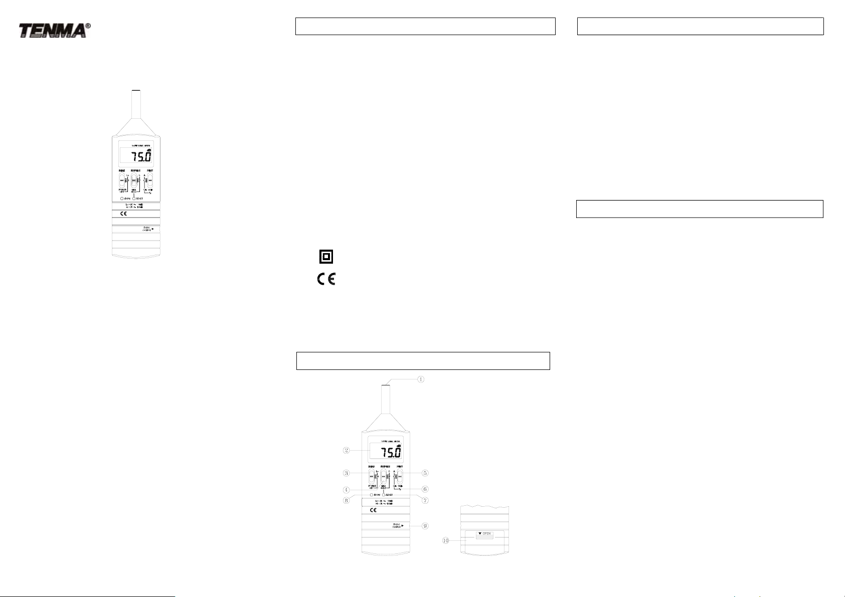
4. DESCRIPTION OF CONTROLS
4
c
Microphone
1/2 inch Electric Condenser microphone
d
Display
Serves to display the sound pressure level (dB), over or under range “OVER” ,
maximum hold data “MAX HOLD” and Low battery indicator “BT”.
dB
: Sound pressure level with 0.1dB resolution.
OVER
: Shown when the range setting is too high (or Low) .
e
Power and Range switch
z
Turn power ON and select measurement range.
(Hi range = 65~130dB, Lo range = 35~100dB)
z
When “OVER” is indicated, Slide range switch to another range for measurement.
f
Response and Max hold switch
Setting the meter dynamic characteristics (Fast/slow) and maximum value hold.
S
(slow response) : for comparatively stable noise measurement.
F
(fast response) : for fast varying noise.
MAX HOLD
T o re-fresh please set switch to “F” or “S” position to cancel existing v alue,
then, set switch to “MAX HOLD” position.
: The max hold position is used to measure the maximum level of
sounds. The maximum measured level is up dated continuously.
5
Page 2
g
Function switch (A/C weighting & calibration selector)
A
C
CAL 94dB
h
Calibration control can be adjusted cloc kwise or co untercloc kwise to stand ard 94 .0dB .
i
Reset button :
Serves to reset the maximum level indication.
j
RS-232 button.
k
RS-232 output jack
l
Battery cover (on bottom)
: A-weighting
: C-weighting
: Calibration
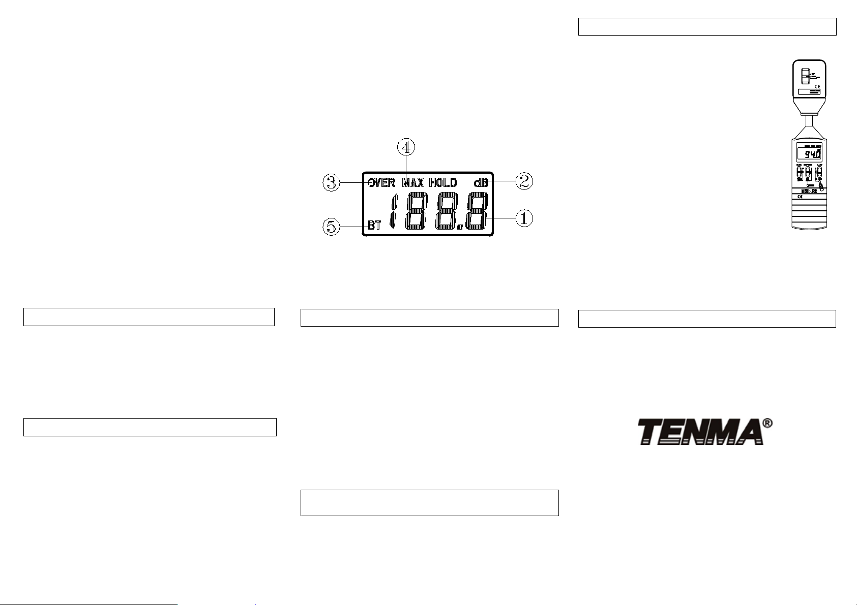
LCD Descr iption
c
Sound Pressure Level measuring value, resolution 0.1dB.
d
Measuring unit
e
When readout is out of range.
f
MAX HOLD: Maximum hold.
g
BT: Low battery indicator.
5. CALIBRATION PROCEDURES
(1). Using a acoustic calibrator
a).
Make the following switch settings.
RANGE : Hi
RESPONSE : F
FUNCT : A
b). Insert the microphone carefully into the in sertion hole of
the calibrator.
c). T urn on the s witch of calibrato r and adjust the CA L screw of
the instrument, until the level display indicates the desired
level.
Note: Our products are well calibrated before shipment.
Recommended calibrator cycle is one year.
(2). Calibration using the internal oscillator
a).
Make the following switch settings.
RANGE : Hi
RESPONSE : F
FUNCT : CAL 94dB
b). Display will show 94.0 ± 1.5dB
6
6. MEASUREMENT PREPARATION
(1). Battery Loading:
Remove the battery cover on the back of the unit replace 9V battery and refit
battery cover.
Note : make sure the battery polarity is correct.
(2). Battery Replacement:
When the battery voltage drops below the operating voltage, “ BT “ mark will
appear in the display and, battery should be replaced with new one.
7. OPERATING PRECAUTIONS
(1). Wind blowing acros s th e mi cr op ho n e wo u l d cause additional extr aneous noises.
When using the instrument in the presence of wind, you must use the
windscreen to avoid any undesirable signals.
(2). Calibrate the instrument before operation if the unit has been left used for any
length of time is being operated in poor conditions.
(3). Do not store or operate this instrument at high temperature and in a high
humidity environment for any length of time.
(4). Keep microphone dry and avoid severe vibration.
(5). Please take out the battery and keep the instrument in low humidity environment
when not in use.
9
7
8. MEASUREMENT
(1). Open battery cover and install a 9-volt battery in the battery compartment.
(2). Turn on power and select the desired response a nd weighting. If the sound source
consists of short bursts or only catching sound peak, set RESPONSE to FAST. To
measure average sound level, use the slow setting.
Select A- weighting for general noise sound level and C-weighting for measuring sound
level of acoustic material.
(3). Hold the instrument comfortably in hand or fix on tripod and point the microphone at
the suspected noise source, the sound pressure level will be displayed.
(4). When MAX HOLD mode is chosen. The instrument captures and holds the maximum
noise level for a long period.
Press “ RESET” button to reset the maximum level indica ti on.
(5). Turn OFF the instrument when not in use.
(6). For RS-232 measurements please refer to the instruction manual enelosed on the CD-ROM.
9. RS-232 INTERFACE, SOFTWARE INSTALLATION and
OPERATION
For the detailed instruction, please refer to the content of attached
CD-ROM, which has the complete instruction of RS-232 interface,
software operation and rel evant information.
RS-232 protocol : are enclosed within the content of CD-ROM, please
open the CD-ROM for details.
10
8
10. SERVICE, REPAIR AND CALIBRATION
For service, repair and calibration pl ease contact your local Tenma distributor
or go to http://www.tenma.com
TEST EQUIPMENT
405 Pioneer Blvd.
Springboro, Ohio, 45066
http://www.tenma.com
Mar-2007-1
Page 3

Dat alogger and RS232 Interface
RS232 Wiring Hardware ……………………………………………………………2
RS232 Protocol ………………………………..…………………………………..3
Hardware Requirements and Setup ………………………………………………4
Software Requirements and Setup …………………..……………………………5
Communicating Operation …………………….……………………………………8
Run the Software …………………………………...…….………………….….8
Record………..……………………………………………………………………10
Download…...………………………..……………………………………………11
Data Convert....……….……………..……………………………………………12
Apply for Excel ……………………………………………………………………12
Apply for Graph……………………………………………………………………15
Sampling Time…………………………..…………………………..…………….16
1
Page 4
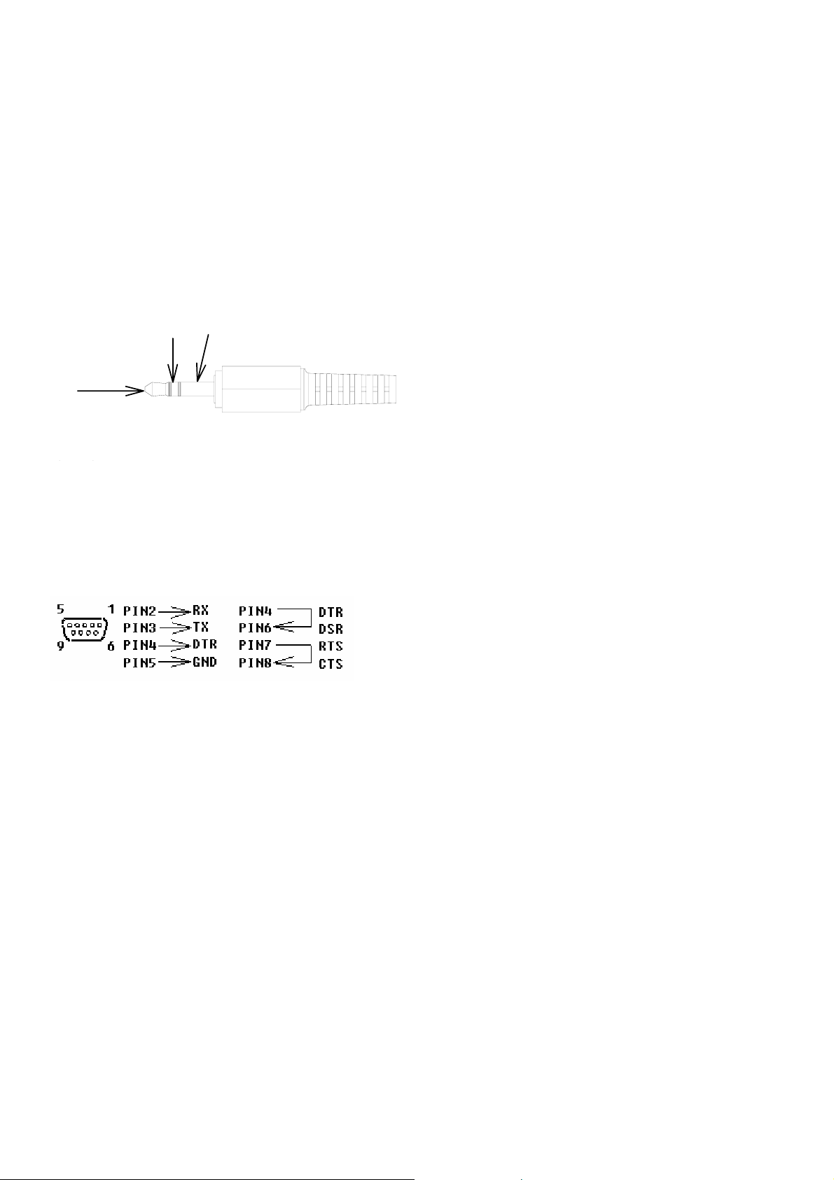
RS232 Wiring Hardware
PC Interface Cable
Meter side of PC Interface Cable
The RS-232 “phono” plug side of the PC Interface Cable connects to the meter’s RS-232 phono
jack. Refer to the diagram below for wiring information.
RX
TX
GND
Computer’s Serial Port side of Interface Cable
The RS-232 “DB-9” side of the PC Interface Cable connects to the PC’s COM port. Refer to the
diagram below for wiring information. Note that a SERIAL to USB Adapter may be used.
RS232 Settings
19200, N, 8, 1
2
Page 5
RS232 Protocol
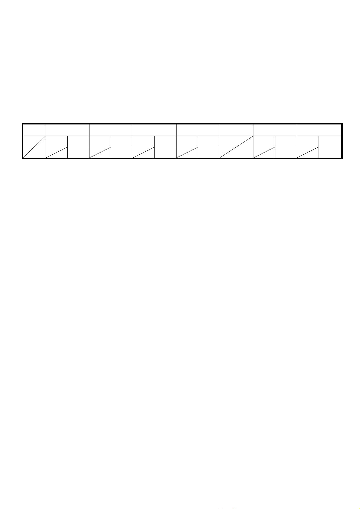
1. RS232 Settings :
c
Baud rate : 19200bps d Parity check : None e Data bits : 8 f Stop bit : 1
2. Transfer Format :
Command : “SPACE” Key
Protocol :
Byte 1 Byte 2 Byte 3 Byte 4 Byte 5 Byte 6789 Byte 10 Byte 11
bit4~6 bit0~3 bit4~6 bit0~3 bit4~6 bit0~3 bit4~6 bit0~3 bit4~6 bit0~3 bit4~6 bit0~3
100 10 1 0.1
1101 1010
Byte 1 : Don’t Care
Byte 2,3,4,5 : LCD Bytes
Byte 6,7,8,9 : Don’t Care
Byte 10,11 : Checking Code
3
Page 6

Hardware Requirements and Setup
PC HardWare Requirements :
HDD, CD Rom, 486 PC or above, with available COM port
EGA or higher monitor
4M bytes or more memory size
PC HardWare Setup :
1) Switch off all power related to the PC
2) Connect the DB9 (female) end of the supplied RS-232 cable to available COM port
3) Switch on all related power
4) Connect the phono plug end of the RS232 cable to the meter
4
Page 7

Software Requirements and Setup
1) Start up windows 98 / XP operating system
2) Close all other applications
3) Insert disk in CD drive
Wait for “Autorun” to start and follow on-screen instructions
(If “autorun” does not start, click on “Start” then “Run”. Type the drive letter and
“: \Disk1\Setup.exe” and click “OK” .)
1).
Setup program will run automatically.
2).
Click Next> button
5
Page 8

3).
a. Click Next> to use the default folder
or
b. Click Browse… to select a different folder
4).
Click Next> button
6
Page 9

Setup is complete.
7
Page 10

Communicating Operation
Run the software
1. Click "Start" form Start menu then move to "All Programs" (or “Programs”) then "SLM" and
then click the "SLM" icon.
8
Page 11

2.
Click an available COM port
3. Main software screen
9
Page 12

Record
Save to Hard Disk (PC)
Click button. The dialog box shown below will appear.
Input a file name and then click "Save" to begin saving data to the file just named.
Click button to stop recording.
10
Page 13

Download Data
1. Download Data from Hard Disk
Click button. The Open window, shown below, appears
Input the file that was selected earlier and then click the Open button.
11
Page 14

Data Convert
Apply for Excel
Open Microsoft Excel, find the file saved in Excel type, for example, test.xls.
or find any file already saved in HDD, for example, sample.dat.
12
Page 15

The "Text Import Wizard" then appears. Follow the steps 1 to 3 to complete.
Click Next> button
Click Next> button
13
Page 16

Click Finish button
14
Page 17

Apply for Graph
Open a saved data file in the software program and then click .
15
Page 18

Sampling Time
PC Sampling Rate:
(rate at which the PC collects readings while connected to the meter)
Click on the Menu Bar.
In the Input Sampling Time dialog box, input a sampling time and then click
"OK" button to confirm.
16
 Loading...