

Page 1
72-820
Infrared
Thermometer
Page 2

Model 72-820
OPERATING MANUAL
Page 3

Model 72-820: OPERATING MANUAL
Table of Contents
Title Page
Introduction
Safety Information
Features
Display
Buttons and Connector
How the Thermometer works.
Operating the Thermometer
Locating a Hot or Cold Spot
Distance and Spot Size
Field of View
Emissivity
Trigger Lock
Switching oC/ oF
HOLD
Typical Measurements
Testing Contactors (Starters)
Testing Enclosed Relays
Testing Fuses and Buss Connections
Testing Electrical Connections
5
5
7
7
9
10
10
10
11
11
12
15
15
15
15
16
16
16
17
1
Page 4

Model 72-820: OPERATING MANUAL
Table of Contents
Title Page
Scanning Walls for Air Leaks or Insulation Deficiencies
Testing Bearings
Testing Belts and Sheaves
Checking Hydronic Radiant Heat Applications
Measuring Grille, Register, or Diffuser Discharge
Temperature
Checking for Blockage in Air-To-Air Evaporators or
Condensers
Maintenance
Changing the Battery
Cleaning the Lens
Cleaning the Housing
Troubleshooting
CE Certification
Specifications
Infrared
Laser
Electrical
Physical
Environmental
17
18
19
20
20
21
21
21
21
21
22
22
23
23
24
24
24
24
2
Page 5

Model 72-820: OPERATING MANUAL
Table Title Page
1. Symbols
2. Buttons and Connector
3. Surface Emissivity
4. Troubleshooting
List of Tables
6
9
13
22
3
Page 6

Model 72-820: OPERATING MANUAL
List of Figures
Figure Title Page
1 Symbols and Safety Markings
2 Infrared Thermometer
3 Thermometer Display
4 Buttons and Connector
5 Locating Hot or Cold Spot
6 Distance and Spot Size
7 Field of View
7
7
8
9
10
11
11
4
Page 7
Model 72-820: OPERATING MANUAL
Introduction
The Model 72-820 Infrared Thermometer (hereafter, the
“Thermometer”) can determine the surface temperature
by measuring the amount of infrared energy radiated
by the target’s surface. They have different distance to
spot (D:S) figure and different temperature range, details
see the contents.It features a temperature range of
0oF~1000oF and a distance-to-spot ratio of 12:1.
The non-contact infrared thermometer features low
power consumption design, allowing extended use
without the need to replace batteries. The highly intuitive
design allows fast easy temperature measurement for
increased efficiency in use.
The Thermometer may also be powered from a standard
computer USB port. This can prove very convenient in
situations were repeated battery changes are not
practical. The Thermometer will automatically select
between battery and USB port power.
Safety Information
Warning
A warning identifies conditions and actions that
pose hazards to the user. To avoid electrical
shock or personal injury, follow these guidelines:
l
Do not point laser directly at eye or indirectly
off reflective surfaces.
l
Before using the Thermometer inspect the
case. Do not use the Thermometer if it appears
damaged. Look for cracks or missing plastic.
l
Replace the battery as soon as the battery
indicator appears.
l
Do not use the Thermometer if it operates
abnormally. Protection may be impaired.
When in doubt, have the Thermometer
serviced.
l
Do not operate the Thermometer around
explosive gas, vapor, or dust.
l
To avoid a burn hazard, remember that highly
reflective objects will often result in lower
5
Page 8
Model 72-820: OPERATING MANUAL
than actual temperature measurements.
Do not use in a manner not specified by this
l
manual or the protection supplied by the
equipment may be impaired.
Caution
To avoid damaging the thermometer or the
equipment under test protect them from the
following:
EMF (electro-magnetic fields) from arc
l
welders, induction heaters, etc.
Static electricity.
l
Thermal shock (caused by large or abrupt
l
ambient temperature changes – all 30 minutes
from the Thermometer to stabilize before use).
Do not leave the Thermometer on or near
l
objects of high temperature.
6
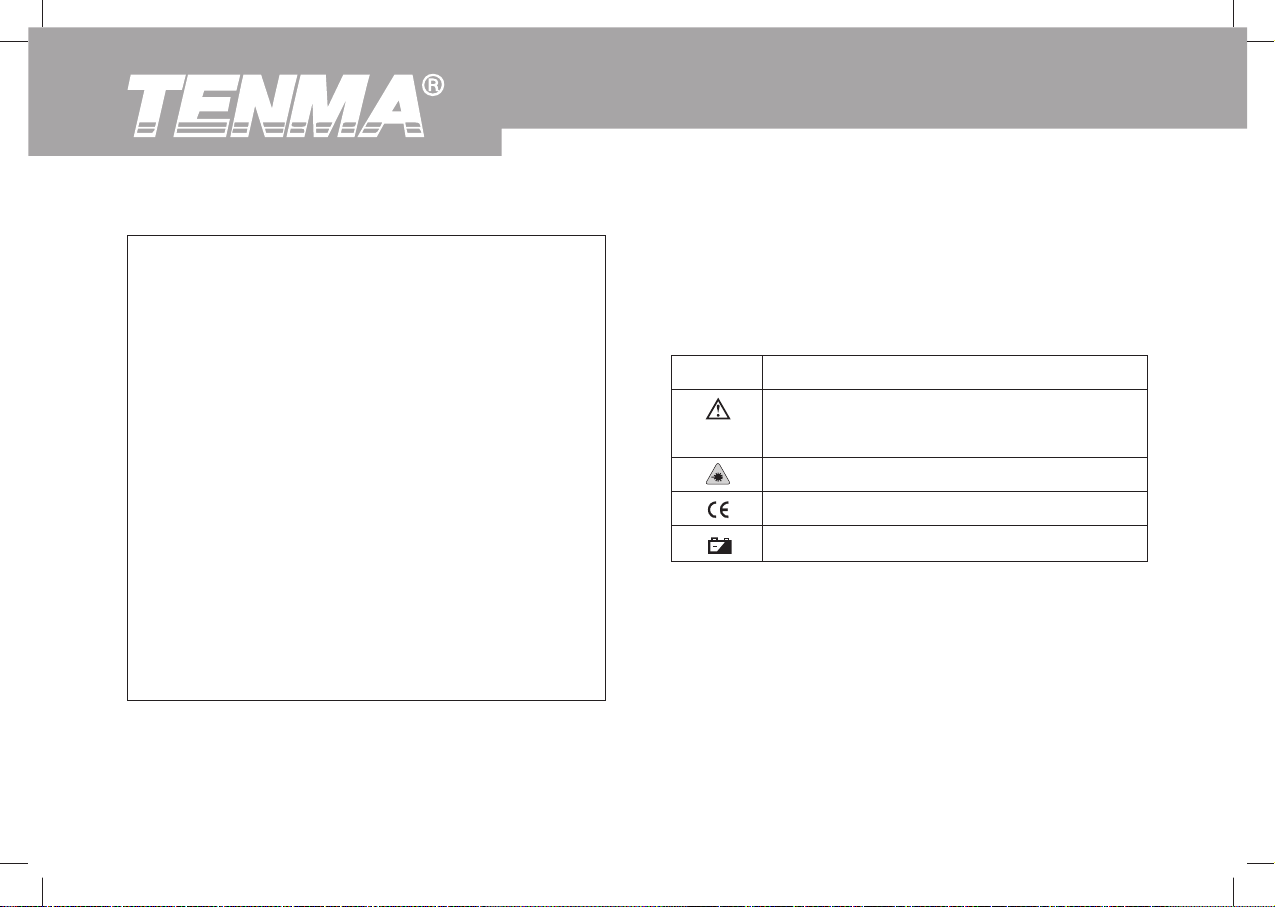
Table 1 and Figure 1 show various symbols and safety
markings that are on the Thermometer and in this
manual.
Table 1. Symbols
Symbol
Explanation
Risk of danger. Important information.
See Manual.
Warning. Laser
Conforms to Standards of European Union
Low battery.
Page 9
Model 72-820: OPERATING MANUAL
l
Celsius and Fahrenheit Temperature Measurement
l
Tripod mount
l
Included 9V Battery
Thermometer features are shown in Figure 2.
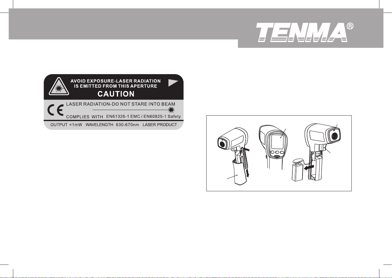
Figure 1. Symbols and Safety Markings
Features
The Thermometer includes:
l
Single-spot Laser Sighting
l
Intelligent USB power source
l
Backlit Display
l
Two level white colour Backlit Display (when using
USB power up, this feature will be on automatically).
l
Current Temperature Plus MIN, MAX, DIF, AVG
Temperature Displays/
l
Easy Emissivity Selector
l
Trigger Lock
Laser
Trigger
Battery Cover
Figure 2. Infrared Thermometer
Display
9V 6F22 Battery
Display
The primary temperature display reports the current or
last IR temperature read until the 8-second hold time
elapses.
7
Page 10

The secondary temperature display reports a choice of
maximum, minimum, difference between maximum and
minimum temperature or average value.
Model 72-820: OPERATING MANUAL
C
You can toggle through the maximum, minimum,
difference and average IR temperatures anytime the
display is on. The MAX, MIN, DIF and AV temperatures
are constantly calculated and updated when the trigger
is pressed. After the trigger is released, the MAX, MIN,
DIF and AV temperatures are held for 8 seconds.
8
A
D
Laser “On” Symbol
HOLD
SCAN
SCAN or HOLD
oC/o
F Symbol (Celsius/Fahrenheit)
A
Primary temperature Display
Secondary temperature Display
B
Emissivity LO, MED, HI
C
Temperature values for the MAX, MIN, DIF,
D
AVG
Low Battery symbol. Appears when the
battery charge is <4.5V.
Figure 3. Thermometer Display
B
Page 11

Model 72-820: OPERATING MANUAL
Buttons and Connector
Figure 4. Buttons and Connector
Button /
Connector
MODE
SET
USB port
Table 2. Buttons and Connector
Description
Press MODE button to toggle between MAX, MIN,
DIF, and AVG options.
Press MODE to turn the Thermometer on again
and displays the last measurement result.
Press to enter set up mode stepping through
Emissivity set up, Trigger Lock and Switching
oC/o
F set up.
Details refer to the below Emissivity, Trigger Lock
and Switching oC/oF topics.
Press
to turn the display backlight on and off.
icon will be on and off also.
When the Thermometer enters the setup up mode,
press to select an option, details refer to the
below Emissivity, Trigger Lock and Switching oC/
o
F topics.
Press
is on,
to turn the laser on and off. After laser
will be shown.
When the Thermometer enters the user setup
mode, press to select an option, details refer
to the below Emissivity, Trigger Lock and Switching
o
C/ oF topics.
After connecting the USB cable, the Thermometer
automatically selects USB power supply and two
levels white colour Backlit Display will be on.
9
Page 12

How the Thermometer Works
Infrared thermometers measure the surface temperature
of an opaque object. The Thermometer’s optics sense
infrared energy, which is collected and focused onto a
detector. The Thermometer’s electronics then translate
the information into a displayed temperature reading
which appears on the display. The laser is used for
aiming purposes only.
Operating the Thermometer
The Thermometer turns on when you press the trigger.
The Thermometer turns off when no activity is detected
for 8 seconds.
To measure temperature, aim the Thermometer at the
target, pull and hold the trigger. Release the trigger to
hold a temperature reading.
Be sure to consider distance-to-spot size ratio and filed
of view. The laser is used for aiming only.
Model 72-820: OPERATING MANUAL
To find a hot or cold spot, aim the Thermometer outside
the target area. Then, slowly scan across the area with
an up and down motion until you located the hot or cold
spot. See Figure 5.
Figure 5. Locating Hot or Cold Spot
10
Page 13

Model 72-820: OPERATING MANUAL
As the distance (D) from the target being measured
increases, the spot size (S) of the area measured by
the unit becomes larger. The spot size indicates 90%
encircled energy. The maximum D:S is obtained when
the Thermometer is 600mm (23.6 in) form the target
resulting in a spot size of 20mm (0.79 in). See Figure 6.
Figure 6. Distance and Spot Size
Make sure that the target is larger than the spot size.
The smaller the target, the closer you should be to it.
See Figure 7.
Figure 7. Field of View
11
Page 14

Emissivity describes the energy-emitting characteristics
of materials. Most organic materials and painted or
oxidized surfaces have an emissivity of about 0.95.
If possible, to compensate for inaccurate readings that
may result from measuring shiny metal surfaces, cover
the surface to be measured with masking tape or flat
black paint (<150 oC / 302 oF) and use the high emissivity
setting. Allow time for the tape or paint to reach the
same temperatures as the surface beneath it. Measure
the temperature of the tape or painted surface.
If you cannot use paint or use tape, then you could
improve the accuracy of your measurements with the
emissivity selector. Even with emissivity selector, it can
be difficult to get a completely accurate infrared
measurement of a target with a shiny or metallic surface.
The Thermometer allows you to adjust the unit’s
emissivity for the type of surface before measured.
Refer to Table 2. But it is only a typical case. You could
Model 72-820: OPERATING MANUAL
base on your own case and materials to have different
setting.
To adjust values for emissivity, follow the below
procedure:
1.
Press SET to select emissivity set up, icon E on the
display is blinking. The Thermometer steps through
emissivity set up, trigger lock and switching oC / oF.
2.
Press to increase the value by 0.01 or press and
hold to access quick setting. The maximum value
is 1.00.
3.
Press to decrease the value by 0.0 or press and
hold to access quick setting. The minimum value
is 0.10.
12
Page 15

Model 72-820: OPERATING MANUAL
Table 3. Surface Emissivity
Measure Surface
METALS
Aluminum
Oxidized
Alloy A3003
Oxidized
Roughened
Brass
Burnished
Oxidized
Copper
Oxidized
Electrical Terminal Blocks
Haynes
Alloy
Inconel
Oxidized
Sandblasted
Electoropolished
Switch Setting
0.2-0.4
0.3
0.1-0.3
0.3
0.5
0.4-0.8
0.6
0.3-0.8
0.7-0.95
0.3-0.6
0.15
Measure Surface
Iron Cast
Oxidized
Unoxidized
Molten
Iron Wrought
Dull
Lead
Rough
Oxidized
Molydbenum
Oxidized
Nickel
Oxidized
Platinum
Black
Steel
Cold-Rolled
Switch Setting
0.6-0.95
0.2
0.2-0.3
0.9
0.4
0.2-0.6
0.2-0.6
0.2-0.5
0.9
0.7-0.9
13
Page 16

Table 3. Surface Emissivity
Model 72-820: OPERATING MANUAL
Measure Surface
Iron
Oxidized
Rusted
NON-METALS
Asbestos
Asphalt
Basalt
Carbon
Unoxidized
Graphite
Carborundum
Ceramic
Clay
Concrete
Cloth
14
Switch Setting
0.5-0.9
0.5-0.7
0.95
0.95
0.7
0.8-0.9
0.7-0.8
0.9
0.95
0.95
0.95
0.95
Measure Surface
Ground Sheet
Polished Sheet
Zinc
Oxidized
Glass
Plate
Gravel
Gypsum
Ice
Limestone
Paper (any colour)
Plastic
Opaque
Soil
Water
Wood, (natural)
Switch Setting
0.4-0.6
0.1
0.1
0.85
0.95
0.8-0.95
0.98
0.98
0.95
0.95
0.9-0.98
0.93
0.9-0.95
Page 17

Model 72-820: OPERATING MANUAL
To lock or unlock the trigger, use the following
procedures:
1. Press SET to select trigger lock setting, the
will blink.
2. Press to select ON or OFF.
When the trigger is locked, the Thermometer will provide
continuous measurement. There is no need to pull the
trigger.
When the trigger is unlocked, the user must pull the
trigger for measurement. When the trigger is released,
the Thermometer will hold the measurement result
automatically.
1. Press SET to choose oC / oF selection mode,
2. Press to select oC or oF.
The display will remain activated 8 seconds after the
trigger is released. HOLD appears in the upper middle
of the display. When the trigger is pulled again, the
Thermometer will begin measuring in the last function
selected.
Typical Measurements
This section describes a variety of measurements often
performed by technicians.
User could select to turn on or off the backlight and
l
laser whenever you are making readings with the
Thermometer. But if you are using USB to power
up the Thermometer, the two levels white colour
backlight will be on automatically.
Relatively high emissivity normally means emissivity
l
setting of about 0.95.
Relatively low emissivity normally means emissivity
l
setting of about 0.30.
When the emissivity of an object is unknown,
l
15
Page 18

the user may cover the surface (temperature >150oC)
with black electric tape (emissivity of about 0.95). Allow
time for the tape to reach the same temperature as the
object to be measured. Measure and record the
temperature of the tape.
Target the Thermometer to the object to be measured,
adjust the emissivity setting to make it as the same
temperature as the tape. At this time, the Thermometer
emissivity setting is close to the emissivity of the object
to be measured, measurement could be started.
1.
Press SET to select emissivity. Press / to select
relatively low emissivity for bright contacts, or 0.7
mid level for darkened contacts.
2.
Press MODE to select MAX.
3.
Measure line and load side of one pole without
releasing trigger.
4.
A temperature difference between the line and load
sides of a pole indicate increased resistance of
one point and a contactor may be failing.
Model 72-820: OPERATING MANUAL
1.
Press SET and then press / to set emissivity to
relatively low for uninsulated connectors or relatively
high for plastic encased relays or for bakelite
enclosed relays or insulated connectors.
2.
Press MODE to select MAX.
3.
Start to scan.
4.
Measure the relay casing, looking for hot spots.
5.
Measure electrical connections on relay terminals
looking for hot spots.
1.
Press SET and then press / to set emissivity to
relatively high for paper covered fuse body or
insulated connections.
2.
Press MODE to select MAX.
3.
Scan the paper covered length of fuse.
4.
Without releasing the trigger, scan each fuse.
Unequal temperatures between fuses may indicate
voltage or amperage imbalance.
5.
Press SET and then press / to set emissivity to
relatively low, for metal fuses and caps and insulated
16
Page 19

Model 72-820: OPERATING MANUAL
buss connections.
6.
Press MODE to select MAX.
7.
Scan each end cap on each fuse/
Press SET and then press / to set emissivity to
1.
relatively low for uninsulated connectors or buss
connections or relatively high for insulated
connections.
Scan the conductor, moving toward direction of
2.
electrical connector (quick connect, wire nut, buss
connection, or lug).
Turn off heating, cooling, and blower.
1.
Press SET to select emissivity. Press / to select
2.
emissivity relatively high for painted surfaces or
window surfaces.
Press MODE to select MIN when opposite side of
3.
wall is at lower temperature and or select MAX when
opposite side of wall is at higher temperature.
Measure an interior partition wall surface temperature.
4.
Do not release the trigger. Record this temperature
as your baseline (or benchmark) for a “perfectly”
insulated wall.
Face the wall to be scanned. Stand 1.5m away to
5.
scan a 5cm spot on the wall.
Scan horizontal rows of wall from top to bottom, or
6.
horizontal rows of ceiling from wall to wall. Look for
greatest deviations from baseline temperature to
identify problems. This completes the insulation test
scan.
17
Page 20

Turn on the blower (no heat, no cooling) and retest. If
test results with the blower on are different than results
with the blower off, this may indicate air leaks in
conditioned envelope walls. The air leaks are caused
by duct leaks that create a pressure differential across
the conditioned space envelope.
Warning
To avoid injury when testing bearings:
Do not wear loose clothing, jewelry, or anything
l
around neck when working around moving parts
such as motors, belts, blower, and fans.
Make sure an electrical disconnect is within
l
reach and operating correctly and freely.
Do not work alone.
l
Model 72-820: OPERATING MANUAL
Press SET and then press / to select relatively
1.
high emissivity.
Press MODE to select MAX.
2.
Enable motor and allow it to reach steady state
3.
operating temperatures.
Disable the motor if possible.
4.
Measure the two motor bearing temperatures
5.
Compare the two motor bearing temperatures.
6.
Unequal temperatures or a high temperature can
indicate a lubrication or other bearing problem that
is resulting from excess friction.
Repeat the sequence for the blower bearings.
7.
18
Page 21

Model 72-820: OPERATING MANUAL
Press SET and then press / to select relatively
1.
high emissivity.
Press MODE to select MAX.
2.
Enable the motor and allow it to reach a steady
3.
state operating temperatures.
Aim the Thermometer at the surface to be measured.
4.
Start recording temperature
5.
Slowly move the Thermometer up the belt toward
6.
second sheave.
If belt is slipping, sheave temperature will be
l
high from friction.
If belt is slipping, belt temperature will remain
l
high between sheaves.
If belt is not slipping, belt temperature will reduce
l
between sheaves.
If inner surfaces of sheaves are not a true “V”
l
shape, this indicates belt slippage and will
continue to operate at elevated temperatures
until sheave is replaced.
Sheaves must be properly aligned (include “pitch
l
& yaw”) for belt and sheaves to operate at appropriate
temperatures. A straight edge or taut string, can be
used to check alignments.
Motor sheave should operate at a temperature
l
consistent with blower sheaves.
If motor sheave is at a higher temperature at motor
l
shaft than at outer circumference, belt is probably
not slipping.
If outer circumference of sheave is at higher
l
temperature than sheave at motor shaft, then belt
is probably slipping and sheaves may be misaligned.
19
Page 22

Radiant heat tubes in the floor will normally run parallel
to the outside walls. Starting at the floor wall juncture,
scan parallel to the wall while moving into the room
away from the wall. Parallel to the outside wall you
should find parallel isothermal rows indicating the
location of heat tubes below the surface. Perpendicular
to the outside wall, you should find rising and falling
temperatures at equal distances. High temperatures
indicate you are scanning a heat tube beneath the floor
surface, low falling temperatures indicate a space
between the heat tubes.
1.
Press SET and then press / to select relatively
high emissivity.
2.
Press MODE to select MAX.
3.
To locate radiant heat tubes in floor, temporarily
elevate the loop temperature to create hotter spots
for identifying tubing runs.
4.
Before releasing trigger, press MODE to toggle
between MIN, MAX, DIF floor temperatures and
record the temperature for future comparison and
trending under similar conditions.
Model 72-820: OPERATING MANUAL
1.
Press SET and then press / to select relatively
high emissivity.
2.
Aim the Thermometer at the discharge air grille,
register, or diffuser.
3.
Measure discharge temperature.
4.
Release trigger to freeze the temperature reading
for 8 seconds and record this temperature.
5.
Grille, register, or diffuser temperature should be
equivalent to discharge temperature at the air
handler.
20
Page 23

Model 72-820: OPERATING MANUAL
Maintenance
1.
Remove panels to gain access to coil return bends
or hairpins.
2.
Press SET and then press / to select relatively
high emissivity for copper tube.
3.
Start the refrigeration system.
4.
Aim the Thermometer at coil turn bends/hairpins.
5.
Start recording temperature.
6.
Take temperature of each return bend/hairpin.
All evaporator return bends/hairpins should be
l
at or slightly above evaporator saturation
temperature from the pressure/temperature
chart.
All condenser return bend/hairpins should be
l
at or slightly less than condenser saturation
temperature.
If a group of return bends/hairpins do not conform
l
to expected temperatures, that indicates a
blocked or restricted distributor or distributor
tube.
To install or change the 9V battery, open the battery
compartment the battery as shown in Figure 2.
Blow off loose particles using clean compressed air.
Carefully wipe the surface with a moist cotton swab.
The swab may be moistened with water.
Use soap and water on a damp sponge or soft cloth.
Caution
To avoid damaging the Thermometer, do NOT
submerge it in water.
21
Page 24

Troubleshooting
Model 72-820: OPERATING MANUAL
Table 4. Troubleshooting
Symptom
OL (on display)
-OL (on display)
Blank Display
Laser does not work
Problem
Target temperature is over range
Target temperature is under range
Low Battery
Possible dead battery
1. Low or dead battery
2. Ambient temperature above 40oC
(104oF)
Action
Select target with specifications
Select target with specifications
Replace Battery
Check and / or replace battery
1. Replace battery
2. Use in area with lower ambient
temperature.
CE Certification
The Thermometer conforms to the following standards:
l EN61326-1 EMC
l EN60825-1 Safety
Certification testing was conducted using a frequency range of 80 to 100MHz with instrument in three orientations.
22
Page 25

Model 72-820: OPERATING MANUAL
Specifications
Measurement Range--------------------------------------------------------18oC to 550oC (0oF to 1022oF)
Spectral Range -------------------------------------------------------------- 8 to 14 microns
Accuracy ---------------------------------------------------------------------- 1.8% or (1.8oC/4oF)
Temperature than less 0oC , Accuracy add to 1oC(2oF)
(Assumes ambient operating temperature of 23 to 25oC (73 to 77oF))
Repeatability ----------------------------------------------------------------- 0.5% of reading or 1oC/2oF
Response Time (95%) ----------------------------------------------------- 250ms
Distance to Spot (D:S) ----------------------------------------------------- 12:1
Emissivty Adjustment ------------------------------------------------------ 0.10~1.00
Display Resulation ---------------------------------------------------------- 0.1oC (0.1oF)
Secondary Display Information ------------------------------------------ Maximum, Minimum, Differential, Average
Sighting --------------------------------------------------------------------------- Single point laser
Power --------------------------------------------------------------------------------- Class 2 (II) operation; Output <1mV , wavelength
630 to 670mm
Power Supply -------------------------------------------------------------------- 6F22 9V Battery
Power Consumption ------------------------------------------------------------ At least 30 hours battery life (Alkarine), At least
10 hours battery life (General Purpose)
23
Page 26

Model 72-820: OPERATING MANUAL
Weight ----------------------------------------------------------------------------- 0.322kg
Size ---------------------------------------------------------------------------------17.69cm (H) x 16.36 cm (L) x 5.18cm (W)
Operating Temperature Range ---------------------------------------------- 0oC to 50oC (32oF to 120oF)
Relative Humidity ----------------------------------------------------------------0 to 75% noncondensing
Storage Temperature ---------------------------------------------------------- -20oC to 65oC (-4oF to 150oF)
24
Page 27

Model 72-820: OPERATING MANUAL
** END **
This operating manual is subject to change without notice.
25
Page 28

Copyright 2007 Tenma Test Equipment.
All rights reserved.
Tenma Test Equipment
405 S. Pioneer Blvd.
Springboro,Ohio 45066
www.tenma.com
Model 72-820: OPERATING MANUAL
26
 Loading...