

Page 1
1
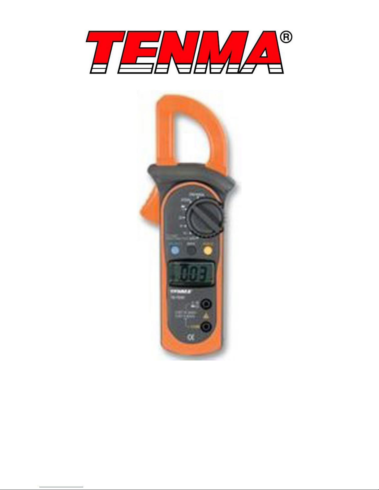
Digital Clamp Meter
Model: 72-7222
Page 2

2
This meter is designed to meet IEC61010-1, 61010-2-032, and 61010-2-033 in
Pollution Degree 2, Measurement Category (CAT II 600V, CAT III 300V) and double
Insulation.
• Do not operate the meter or use test leads if they appear damaged, or if the meter
is not operating properly.
• There are no user-serviceable parts in this product. Refer servicing to qualied
personnel.
• Do not apply voltage between the COM and OHM terminals, while in the
resistance measuring state.
• Do not measure current with the test leads inserted into the voltage or OHM
terminals.
• To avoid electrical shock and personal injury, do not attempt to measure voltage
higher than 600V AC/DC, although the readings may be obtained.
• Do not expose the instrument to direct sunlight, extreme temperature or humidity.
• Before measuring current, check the fuses and turn the power to the circuit off
before connecting the meter to the circuit.
• Disconnect circuit power and discharge all high voltage capacitors before testing
continuity. diode, resistance, capacitance or current.
• Do not use the meter around explosive gas or vapour.
• When using the test leads, keep your ngers behind the nger guards.
• Remove test leads from the meter before opening the meter case or battery door.
• Never operate the meter with the cover removed or the battery door open.
• Use only the test leads supplied or the protection may be impaired.
• Probe assemblies for mains measurements shall be rated as appropriate for
measurement category III according to IEC 61010-031 and shall have a voltage
RATING of at least the voltage of the circuit to be measured.
• Replace the batteries as soon as the low battery indicator appears on the display.
• Remove dead batteries from the meter or if it is not going to be used for a long
time.
• Never mix old and new batteries together, or different types of batteries.
• Never dispose of batteries in a re, or attempt to recharge ordinary batteries.
• Before replacing the battery, turn off the meter and disconnect all the test probes.
• To prolong battery life turn off the meter after use.
SAFETY INFORMATION
Please read these instructions carefully before use and retain for future
reference.
WHAT’S INCLUDED
• Digital multimeter
• Zip case
• User manual
• Test leads
• Two 1.5V AAA batteries
• Point contact temperature probe
Page 3
3
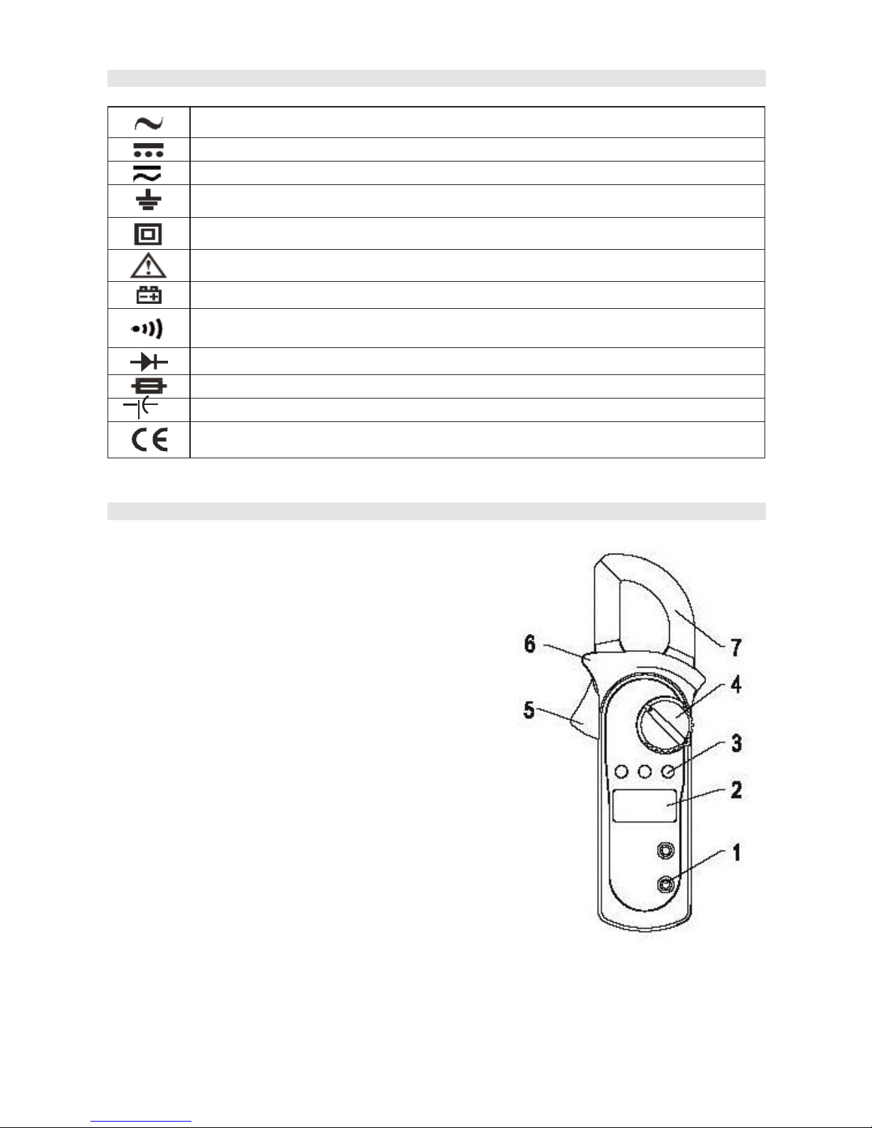
SYMBOL GUIDE
AC (Alternating Current)
DC (Direct Current)
AC or DC
Grounding
Double insulated
Warning
Low battery
Continuity buzzer
Diode
Fuse
Capacitance test
Conforms to European Union directives
FUNCTIONS
1. Input terminals
2. LCD Display
3. Function buttons x 3
4. Range selector
5. Trigger: press and release the trigger to open
and close the detector jaw.
6. Hands guard: protects hands from touching the
dangerous area.
7. Detector jaw: designed to pick up the AC current
owing through the conductor.
Page 4
4
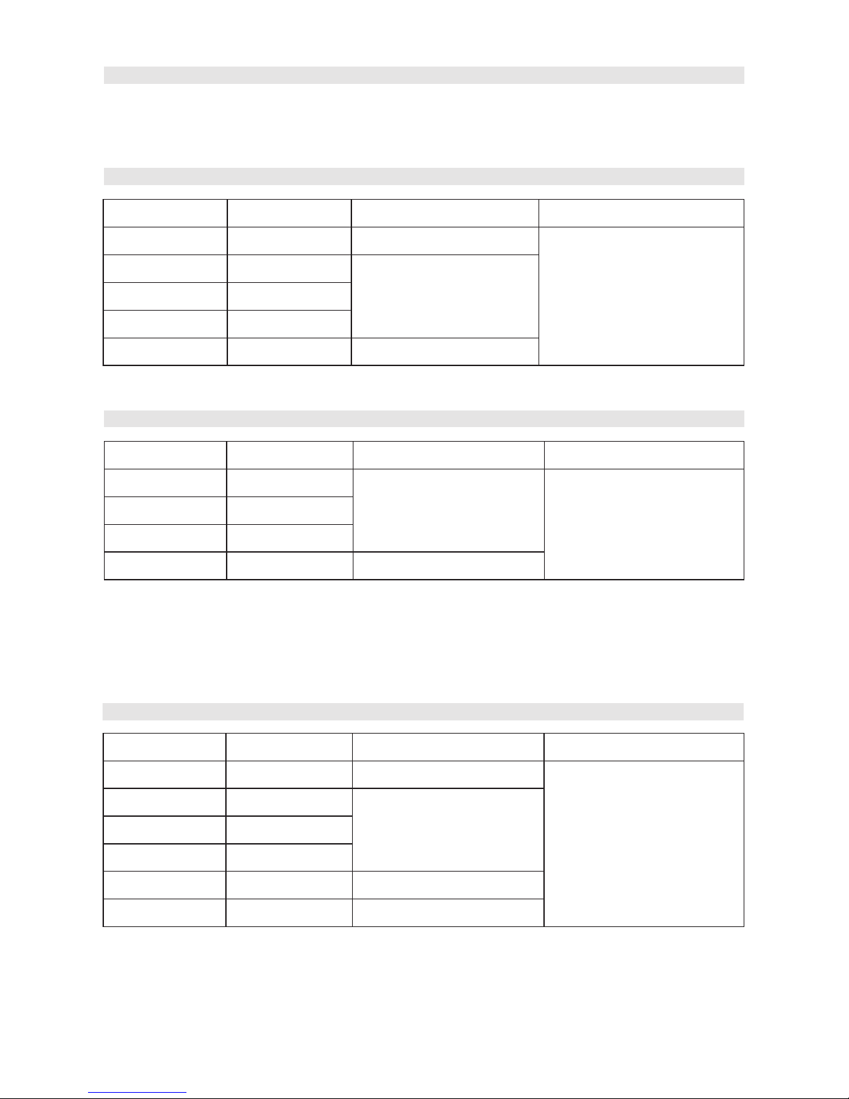
OPERATING PARAMETERS
• Operating temperature: 23°C± 5°C
• Relative Humidity: ≤75%.
• Temperature Coefcient: 0.1× (specied accuracy)/1°C
DC VOLTAGE AUTO RANGING
Range Resolution Accuracy Overload Protection
200.0mV 0.1mV ±(0.8%+3)
600V rms
2.000V 1mV
±(0.8%+1)20.00V 10mV
200.0V 100mV
600V 1V ±(1%+3)
Note: The input impedance is 10MΩ.
AC VOLTAGE AUTO RANGING
Range Resolution Accuracy Overload Protection
2.000V 1mV
±(1.2%+5)
600V rms
20.00V 10mV
200.0V 100mV
600V 1V ±(1.5%+5)
Notes:
• Input Impedance: 10MΩ //<100pF
• Frequency Response: 40Hz~1kHz
• Displays effective value of sine wave (mean value response)
• To adjust reading in accordance with effective value
RESISTANCE
Range Resolution Accuracy Overload Protection
200.0Ω 100mΩ ±(1.2%+2)
600Vp
2.000kΩ 1Ω
±(1%+2)20.00kΩ 10Ω
200.0kΩ 100Ω
2.000MΩ 1kΩ ±(1.2%+2)
20.00MΩ 10kΩ ±(1.5%+2)
Note: The input impedance is 10MΩ.
Page 5
5
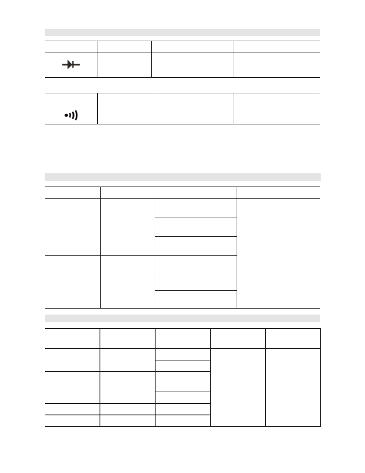
Range Resolution Accuracy Overload Protection
1mV
Displays approximate
forward voltage drop
0.5V~0.8V
600Vp
DIODE AND CONTINUITY
Note: The open circuit voltage is about 1.48V.
Range Resolution Accuracy Overload Protection
100mΩ
When ≤50Ω, the
buzzer beeps.
600Vp
Notes:
• The open circuit voltage is about 0.45V.
• The buzzer may sound when the resistance of a circuit under test is 50Ω~120Ω.
• The buzzer does not sound when the resistance of a circuit under test is higher
than 120Ω.
Range Resolution Accuracy Overload Protection
-40
o
C~1000oC 1oC
-40~0°C
±(3%+9)
600VP
0~400°C:
±(1%+7)
400~1000°C:
(2%+10)
-40
o
F~1832oF 1
oF
-40~32°F:
(3%+10)
32°F~752°F:
(1%+8)
752°F~1832°F:
(2%+18)
TEMPERATURE
AC CURRENT AUTO RANGING
Range Resolution Accuracy Frequency
Response
Overload
Protection
2.000A 0.001A ±(4%+30) ≤1A
50Hz~60Hz 400A rms
±( 3%+12)
20.00A 0.01A ±(3%+12)
≤4A
±(2%+8)
200.0A 0.1A ±(1.5%+5)
400A 1A ±(1%+9)
• Displays effective value of sine wave (mean value response).
Page 6
6
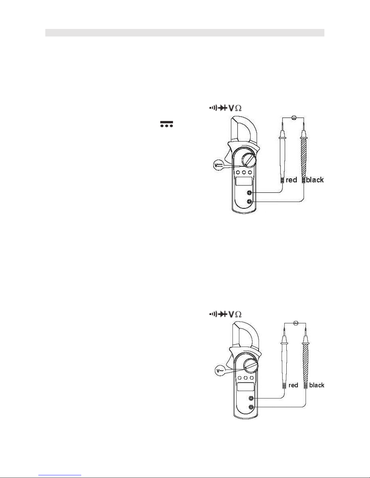
Measuring AC Voltage
Warning
• To avoid damage to the meter, or risk of personal injury, do not attempt to measure
higher than 600V.
• The AC voltage ranges are 2.000V, 20.00V, 200.0V and 600V.
• To measure AC voltage, perform the following steps:
1. Insert the red test lead into the Hz Duty% terminal and the black
test lead into the COM terminal.
2. Turn the range selector to V
~
3. Connect the test probes with the object
being measured.
4. The measured value shows on the display.
Note:
• In each range, the meter has an input
impedance of 10mW. This loading effect can
cause measurement errors in high impedance
circuits. If the circuit impedance is less than or
equal to 10kW, the error is negligible (0.1 or less).
• When AC voltage measurement has been completed, disconnect the test leads
from the circuit under test, and remove them from the input terminals.
OPERATION
Measuring DC Voltage
Warning
• To avoid damage to the meter, or risk of personal injury, do not attempt to measure
higher than 600V.
• The DC voltage ranges are 200.0mV, 2.000V, 20.00V, 200.0V and 600V.
• To measure DC voltage, perform the following steps:
1. Insert the red test lead into the Hz Duty%
terminal and the black
test lead into the COM terminal.
2. Turn the range selector to
3. Connect the test probes with the object
being measured.
4. The measured value shows on the
display.
Note:
• In each range, the meter has an input
impedance of 10MW. This loading effect can
cause measurement errors in high impedance
circuits. If the circuit impedance is less than or
equal to 10kW, the error is negligible (0.1 or less).
• When DC voltage measurement has been completed, disconnect the test leads
from the circuit under test and remove them from the input terminals.
Page 7
7
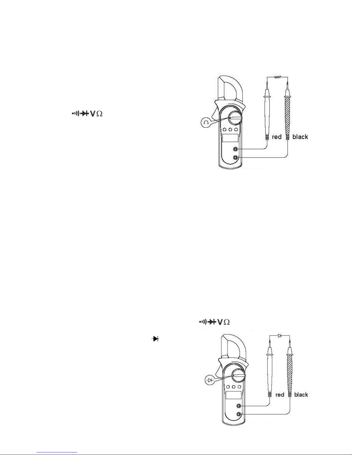
Measuring Resistance
Warning
• To avoid damage to the meter or to the devices under test, disconnect circuit
power and discharge all the high-voltage capacitors before measuring resistance.
The resistance ranges are 200.0Ω , 2.000kΩ ,
20.00kΩ ,200kΩ ,2.000MΩ and 20.00MΩ.
• To measure the resistance, perform the
following steps:
1. Insert the red test lead into the Hz Duty%
terminal and the black test
lead into the COM terminal.
2. Turn the range selector to Ω. Press
SELECT to select Ω mode.
3. Connect the test probes with the object
being measured. The measured value
shows on the display.
Notes:
• The test leads can add 0.1Ω to 0.3Ω of error to resistance measurement.
• For high-resistance measurement (>1MΩ), it normally requires several seconds to
obtain a stable reading.
• If reading with shorted test leads is not 0.5Ω, check for loose test leads, wrong
function selected, or enabled data hold function.
• The LCD displays OL indicating open-circuit or the tested resistor value is higher
than the maximum range of the meter.
• Removing the object under test from its circuit will allow more accurate
measurement.
• When resistance measurement has been completed, disconnect the test leads
from the circuit under test, and remove them from the input terminals.
Testing Diodes
• Use the diode test mode to check diodes, transistors and other semiconductor
devices. In diode test mode, a current is sent through the semiconductor junction
and the voltage drop across the junction is measured.
• To test a diode out of a circuit, perform the following steps,
1. Insert the red test lead into the Hz Duty%
terminal and the black
test lead into the COM terminal.
2. Turn the range selector to .
Press SELECT to switch from diode
measurement mode as default to
continuity measurement mode if needed.
3. For forward voltage drop readings on any
semiconductor component, connect the
red test probe to the component’s anode
and the black test probe to the cathode.
Page 8
8
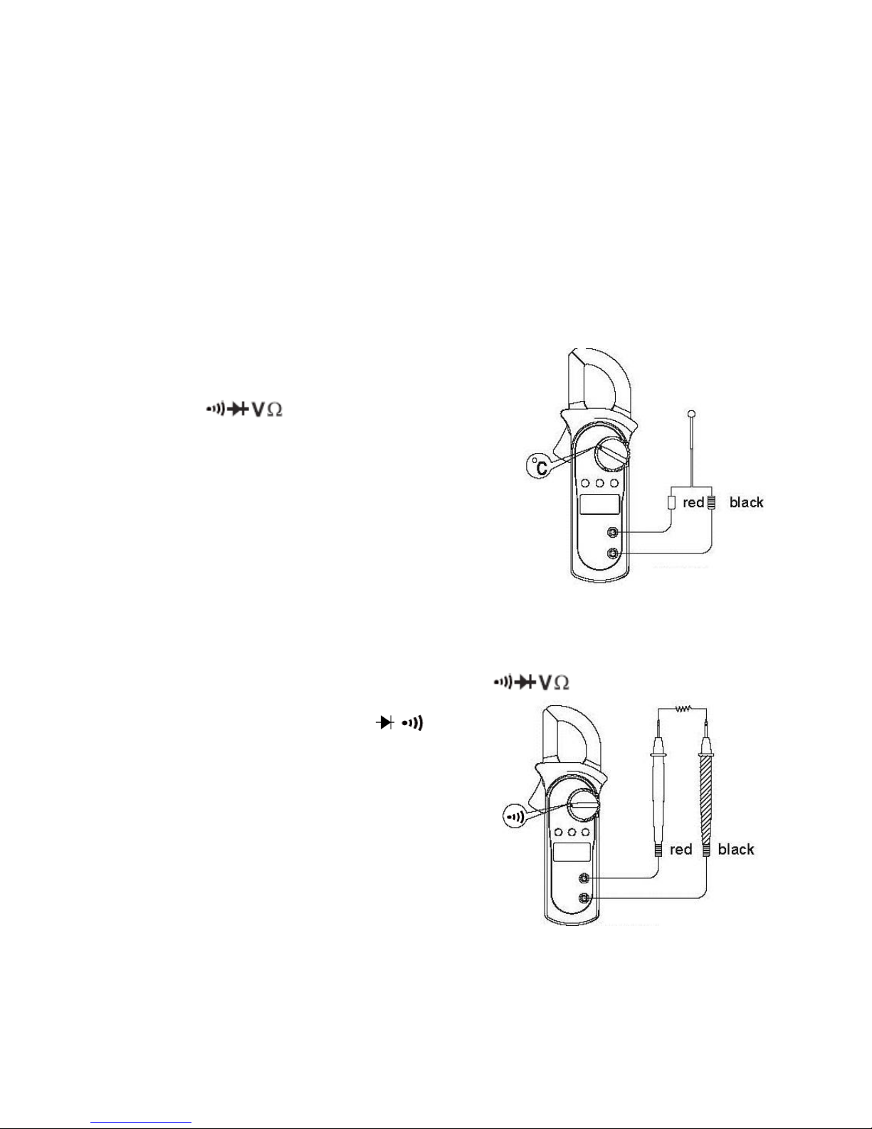
Measuring Continuity
• To test continuity, perform the following steps:
1. Insert the red test lead into the Hz Duty% terminal and the black
test lead into the COM terminal.
2. Turn the range selector to and
press SELECT button to choose the
measurement mode.
• The buzzer will sound if the resistance of a
circuit under test is less than 50Ω.
• The buzzer may sound if the resistance of a
circuit under test is between 50Ω and 120Ω.
• The buzzer does not sound if the resistance of
a circuit under test is higher than 120Ω.
Note:
• The buzzer beeps once when pressing any buttons at any range selector positions
except at 2/20A positions if the button is valid. If the button is not valid, it does not
beep. At 2/20A range selector position, the buzzer is set not to beep.
• Approximately one minute before entering sleep mode, the buzzer will beep five
times. Immediately before entering sleep mode, the buzzer will provide one long
beep.
Measuring Temperature
• The temperature measurement ranges are -40°C~1000°C and -40°F~1832°F.
• To measure temperature, connect the meter as
follows:
1. Insert the red temperature probe into
the terminal and the black
temperature probe into the COM terminal.
2. Turn the range selector to °F°C and press
SELECT button to choose the measurement
mode.
Note:
• The meter automatically displays the temperature
value inside the meter when there is no
temperature probe connection.
Notes:
• In a circuit, a good diode should still produce a forward voltage drop reading of
0.5V to 0.8; however, the reverse voltage drop reading can vary depending on the
resistance of other pathways between the probe tips.
• The LCD will display OL indicating either open circuit or wrong polarity connection.
• The unit of diode is volt (V), displaying the forward voltage drop readings.
• To obtain a more precise reading, you could remove the object being measured
from the circuit when measuring.
• When diode testing has been completed, disconnect the test leads from the circuit
under test, and remove them from the input terminals.
Page 9
9
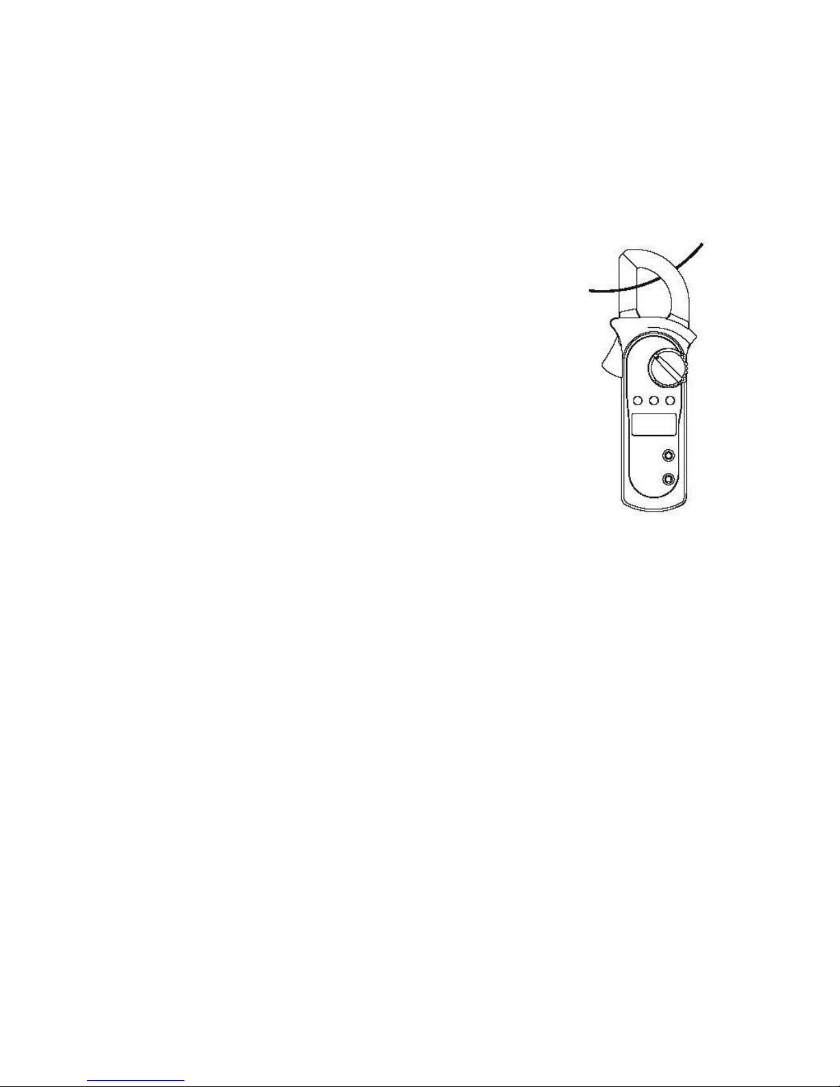
Measuring AC Current
Warning
• To avoid electric shock, never measure current while the test leads are inserted
into the input terminals. Never attempt an in-circuit current measurement where
the open-circuit voltage between the circuit and the ground
is greater than 600V.
• To measure current, do the following:
1. Set the range selector to 2/20A or 200/400A
2. Press the trigger to open the detector jaw.
3. Center the conductor within the detector jaw.
• The measured value shows on the display, it is an effective
value of sine wave (mean value response).
Note:
• To obtain accurate reading, measure only one conductor at
each time.
• When current measurement has been completed, press the
lever to open the transformer jaw again and remove the jaw
from the conductor under test.
Sleep Mode
To preserve battery life, the meter automatically turns off after 15 minutes of inactivity.
The meter can be activated by turning the range selector or pressing any button with
the following conditions:
1. If the meter enters sleep mode while in the temperature function, the meter
cannot be activated by turning the range selector to an AC current range.
2. If using a Function Button to exit the sleep mode, only Function Buttons valid
to the range selector position will be effective.
3. The Hold function will be cancelled if the meter is activated by pressing the
HOLD button.
• To disable the Sleep Mode function, press and hold HOLD button while turning on
the meter.
• The LCD displays OL indicating the circuit being tested is open.
• When continuity testing has been completed, disconnect the test leads from the
circuit under test, and remove them from the input terminals.
Page 10
10
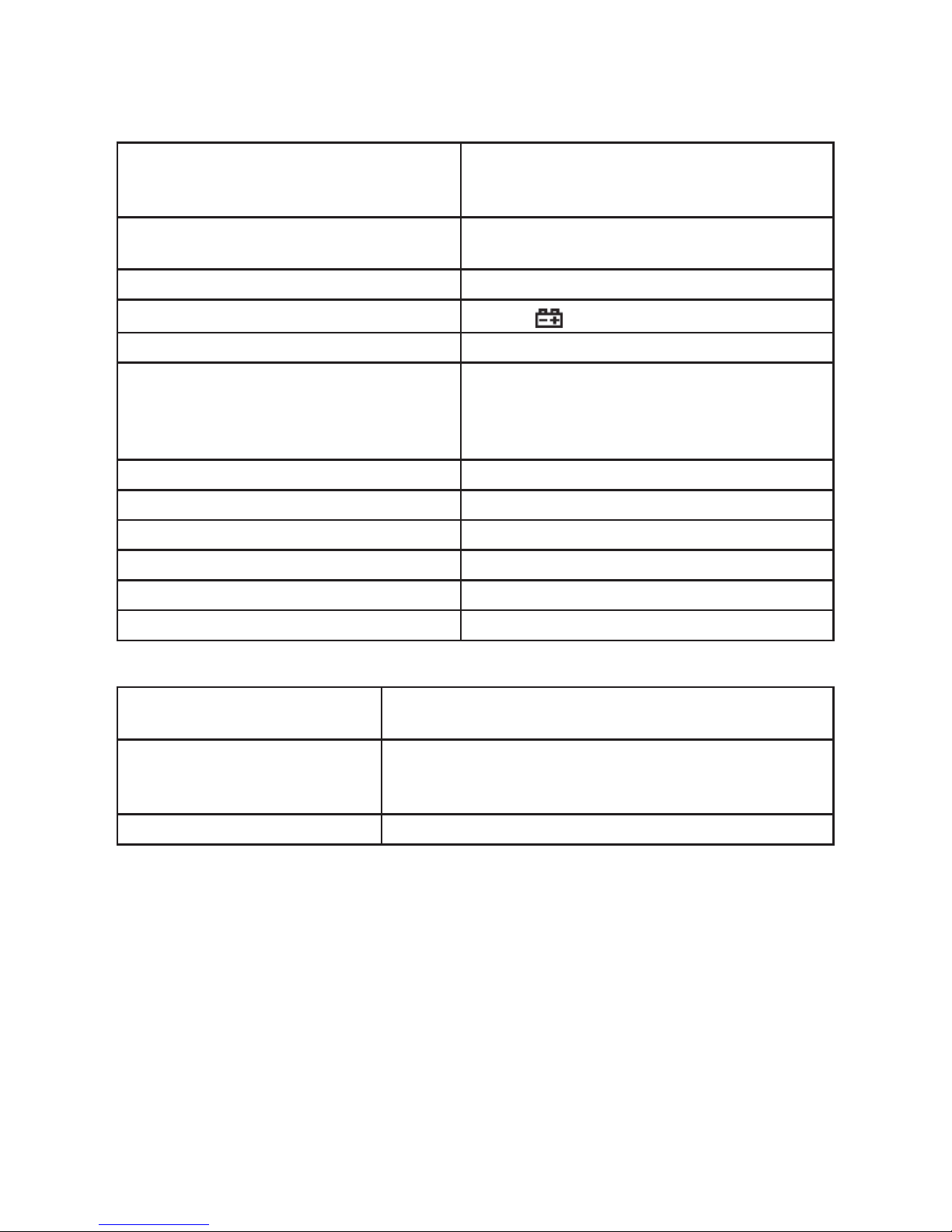
Specications
A. General Specications:
Maximum voltage including transient
overvoltage between any terminals and
ground:
500V rms.
Auto Polarity Display: 3 1/2 digits LCD display,
Maximum display 1999
Overload : Display OL or –OL
Low battery :
Display
Measurement Speed : Updates 3 times/second.
Measurement Deviation : When the conductor being measured is not
placed centrally through the jaws during
AC current measurement, it will cause 1%
reading deviation.
Max. Jaw Size : 1.1” (28mm) diameter.
Projected Max.Current conductor size : 1.0” (26mm) diameter.
Power : 1.5V battery (AAA) x 2off
Battery Life : typically 150hours (alkaline batteries)
Dimensions (H x W x L) : 1.2” x 3.0” x 8.2”.
Weight : Approximate 260g (battery included)
B. Environmental Restrictions:
Altitude : Operating: 2000m
Storage: 10000m
Temperature and humidity: Operating: 0
o
C~30oC (75% R.H)
30oC~40oC ( 70%R.H)
40oC~50oC (45%R.H)
Storage: -20
o
C~+60oC ( 75%R.H)
Page 11
11
MAINTENANCE
Cleaning
• Clean the meter with a clean, soft cloth.
• Do not use any chemicals, abrasives or solvents that could damage the meter.
• Clean the terminals with a mild detergent, as dirt on the terminals can affect
readings.
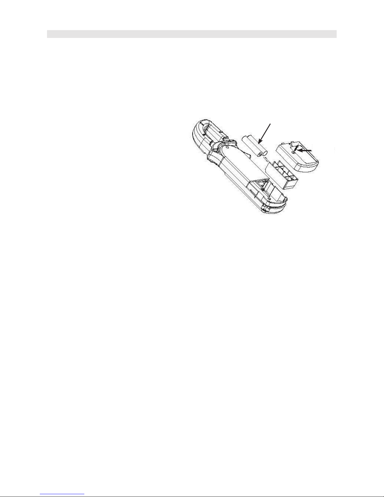
Replacing the battery
• When the meter displays the low
battery symbol, replace the battery
immediately in order to maintain
normal operation.
• Disconnect and remove all test
probes from any live source and the
meter.
• Open the battery cover on the rear
case with a screwdriver.
• Remove the old battery and t a new
9V battery into the battery holder.
• Replace the battery cover.
Screw
Battery
Page 12

12
INFORMATION ON WASTE DISPOSAL FOR CONSUMERS OF
ELECTRICAL & ELECTRONIC EQUIPMENT
These symbols indicate that separate collection of Waste Electrical and Electronic Equipment
(WEEE) or waste batteries is required. Do not dispose of these items with general household
waste. Separate for the treatment, recovery and recycling of the materials used. Waste batteries
can be returned to any waste battery recycling point which are provided by most battery retailers.
Contact your local authority for details of the battery and WEEE recycling schemes available in
your area.
Made in China. PR2 9PP
Man Rev 1.0
 Loading...