

Page 1
1
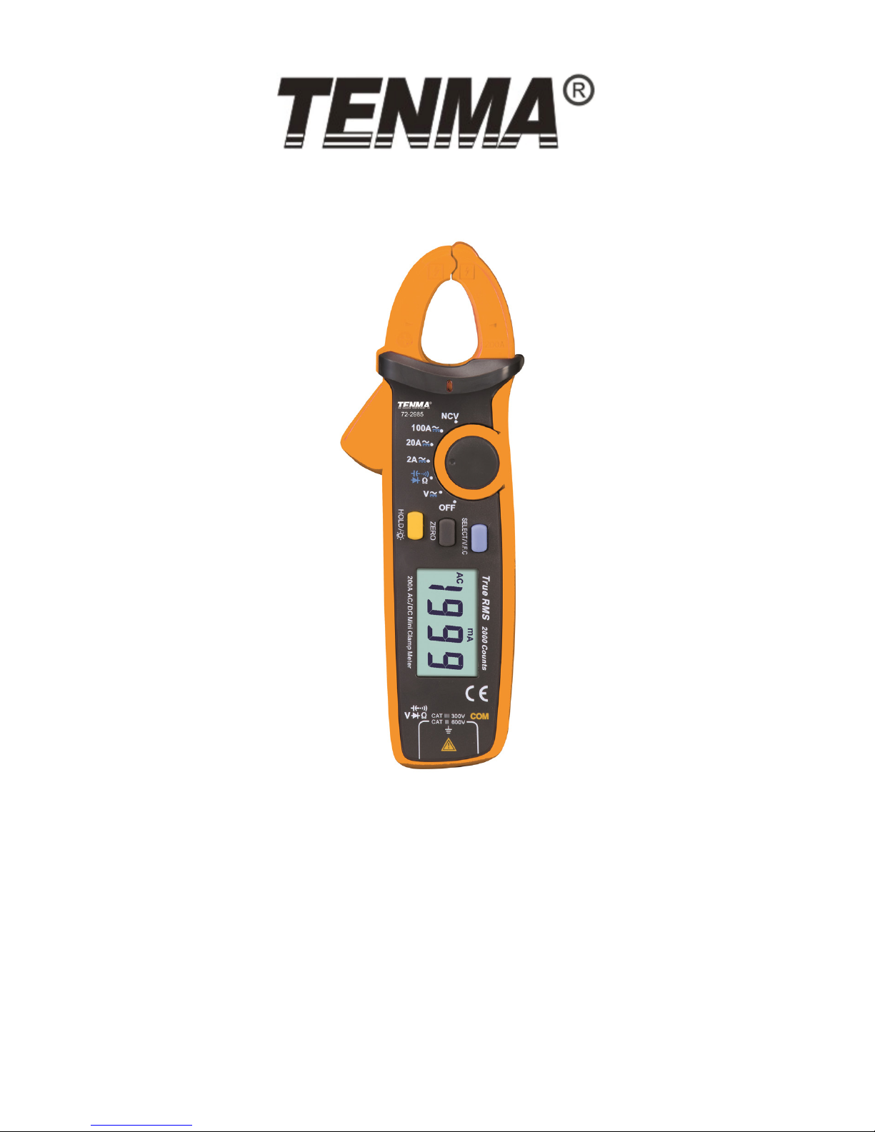
Mini Clamp Meter
Model: 72-2985
Page 2
2
CONTENTS
Page Number Details
2 What’s Included
3 Important Safety Information
3 Technical Specication
4 Product Overview
5 LCD Overview
6 Operation - AC/DC Voltage Measurement
6 Resistance/Circuit On-Off/Diode/Capacitance
6 AC/DC Current Measurement
7 NCV Non-contact Electric Field Measurement
7 Other Functions
8 Technical Index
8 DC Voltage Measurement
8 AC Voltage Measurement
8 Resistance Measurement
9 Circuit On-Off, Diode Measurement
9 Capacitance Measurement
9 DC Current Measurement
9 AC Current Measurement
10 Cleaning & Maintenance
WHAT’S INCLUDED
• One mini clamp meter
• One pair of probe assemblies
• One zip case
• One user manual
Page 3

3
IMPORTANT SAFETY INFORMATION
Please read these instructions carefully before use and retain for future
reference.
• When using electrical appliances basic safety precautions should always be
followed.
• Use the meter only as specied in this manual, or the protection provided may be
impaired.
• Do not operate the meter or use test leads if they appear damaged, or if the meter
is not operating properly. Check before each use.
• There are no user-serviceable parts in this product. Refer servicing to qualied
personnel.
• Do not use the clamp meter in a circuit with voltage higher than 600V or frequency
higher than 400Hz.
• Be cautious when working in an environment with exposed conductors. Contact
with conductors may result in electric shock.
• Use caution with voltages above 60V DC, 30V AC rms or 42V AC (peak value).
These voltages pose a shock hazard.
• Before removing the battery cover, remove the clamp meter from all energized
circuits and disconnect the lead.
• Replace the batteries as soon as the low battery indicator appears on the display.
• Fit a full set of batteries at one time.
• Remove dead batteries from the meter or if it is not going to be used for a long
time.
• Never mix old and new batteries together, or different types of batteries.
• Never dispose of batteries in a re, or attempt to recharge ordinary batteries.
TECHNICAL SPECIFICATION
Max. voltage between input terminal
and earthing
600V
Max. overload protection for clamp
head terminals
100A
Max. display
2000 counts, update 2-3 times per
second
Over range display Displays “OL”
Diode (approx) 3.2V
Range Automatic
Polarity Automatic
Work temperature 0°C ~ 40°C
Relative humidity 0°C ~ 30°C: 75%, 30°C ~ 40°C: 50%
Storage temperature -10°C ~ 50°C
Page 4
4
Electromagnetic compatibility (In
1V/m radio frequency eld)
Overall frequency = designated precision
+ 5%, radio frequency eld above 1V/m
has no designated index
Working altitude 0~2000m
Built-in batteries 2 x AAA 1.5V
Low battery LCD displays “ ”
Dimensions (approx.)
175 x 60 x 33.5mm, max. clamp head
size is 17mm
Weight (approx.) 170g (including batteries)
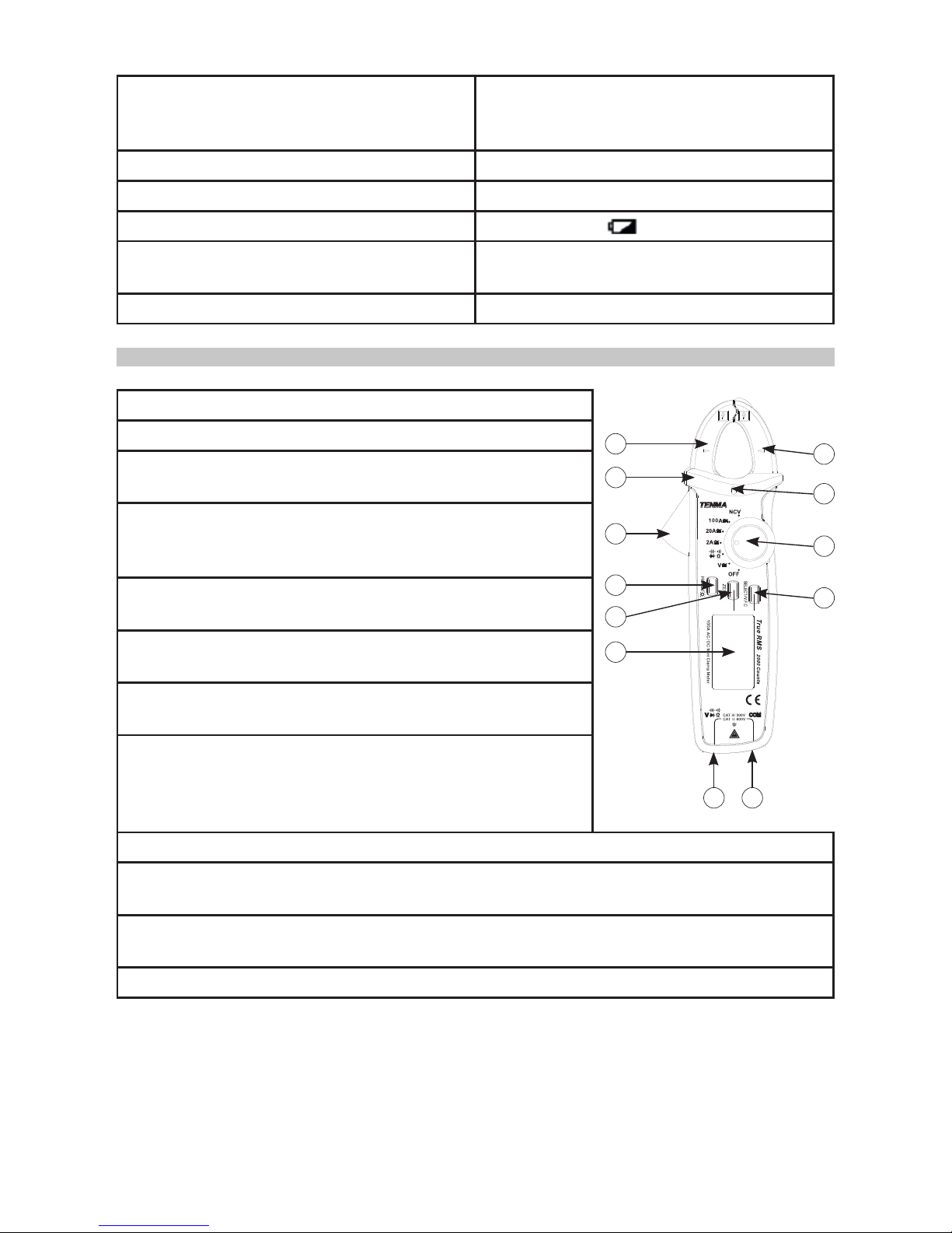
PRODUCT OVERVIEW
1
2
3
4
5
6
7
8
9
10 11
12
1. Clamp head
2. Protective barrier
3. Clamp head trigger: press the trigger to open the
clamp head.
4. NCV Indicator: when the induced AC electric eld
intensity and induction distance satisfy the designated
value, the indicator will ash.
5. Function selection button: rotate to select the
functions indicated.
6. HOLD/backlight key: press and hold to turn on or
off the display backlight.
7. ZERO key: used for DC current zero, capacitance/
voltage measurement relative value.
8. SELECT key: select function mode, such as ACV/
DCV, resistance/on-off/diode/capacitance, ACA/DCA
etc. in AC voltage and current gear. Press and hold for
more than 2 seconds to enter or exit VFC function.
9. LCD screen
10. Positive terminal input jack: when measuring voltage, resistance/on-off/
capacitance/diode, insert the red meter plug into this jack.
11. Input jack at COM terminal: when measuring voltage, resistance/on-off/
capacitance/diode, insert the black meter plug into this jack.
12. Indication mark for geometric centre of clamp head.
72-2985
Page 5

5
LCD OVERVIEW
Indicator Meaning
TRMS True valid value measurement status
AC/DC AC/DC voltage measurement
Negative reading
Diode measurement
Circuit continuity measurement
Data hold
Ω kΩ MΩ Resistance unit
Hz, kHz, MHz Frequency unit
mV, V Voltage unit
mA, A Current unit
nF, µF, mF Capacitance unit
(EF) NCV Non-contact AC voltage induction
Auto Auto range
ZERO/REL Zero/relative measurement
VFC Variable frequency voltage/current measurement
Low battery
Auto power-off
Page 6
6
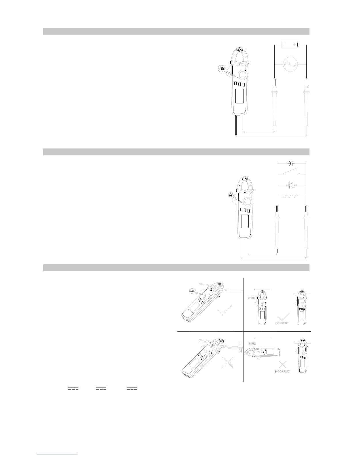
OPERATION - AC/DC VOLTAGE MEASUREMENT
• Select AC voltage or DC voltage range.
• Insert the red meter plug into the red jack (positive
terminal) and the black meter plug into the black
jack (COM terminal).
• Touch the test piece with the red and black meter
plugs.
• Read the measurement value from the LCD.
• WARNING: When measuring voltage, the maximum
input voltage is 600V (AC/DC). Do not exceed this
limitation, otherwise it may cause an electric shock.
RESISTANCE/CIRCUIT ON-OFF/DIODE/CAPACITANCE
• Insert the red meter plug into the red jack (positive
terminal) and the black meter plug into the black jack
(COM terminal).
• Connect the meter plug in parallel to the test piece for
measurement.
• Read the measurement value from the LCD screen.
• WARNING: When measuring resistance/on-off/
capacitance/diode range, do not input voltage over DC
60V or AC 30V to avoid injury.
AC/DC CURRENT MEASUREMENT
AC
• Select AC range (2A~, 20A~, 100A~).
• Open the clamp head, insert the
electric wire and close the clamp head.
• Ensure the electric wire is held in the
geometric centre, indicated on the
clamp head and make sure the clamp
heads are closed.
• Read the measurement data from the
LCD.
DC
• Press SELECT to enter DC range
(2A , 20A , 100A ).
• Press ZERO before measurement to set the reading to zero. If it does not return to
zero after one press, then press it several times until the reading is zero.
Note: As the product is highly sensitive, to ensure correct data measurement, the
orientation of the meter during measurement should be the same as when zeroed.
Page 7
7
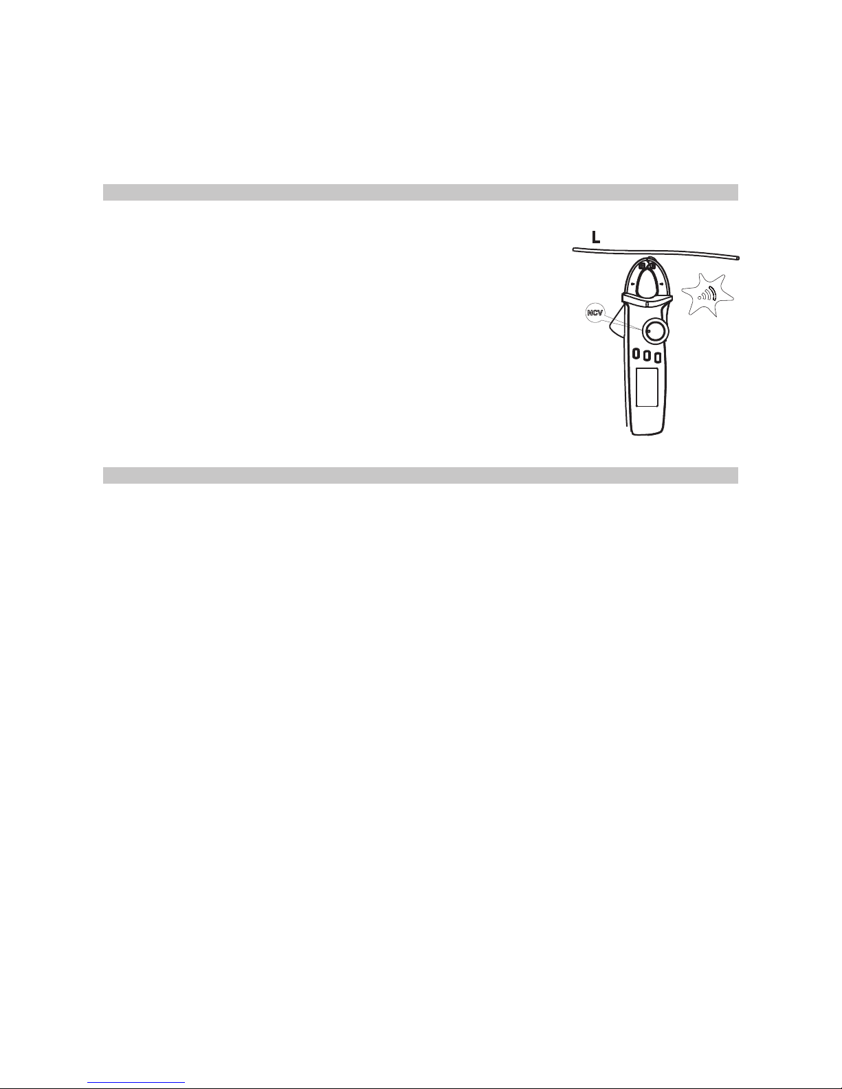
NCV NON-CONTACT ELECTRIC FIELD MEASUREMENT
• If you want to measure whether there is AC voltage/
electromagnetic eld, place the front end of the clamp head
8~15mm close to the test piece.
• When the amplitude of the inductive AC voltage is
approximately ≤ 100V, it displays “EF”.
• If the detected voltage is > 100V, it displays “-” and it has
four “----” levels based on voltage with different buzzing at
each level with NCV light ashing to proportionate to the
eld intensity.
• WARNING: When ranges switch to NCV measurement,
unplug the test plug to avoid electric shock.
OTHER FUNCTIONS
• Press and hold the HOLD button for two seconds to turn on or off the LCD
backlight function.
• Automatic power-off: If the rotary button has not been moved for 15 minutes the
instrument will automatically switch off to save energy. Turn the rotary button to
OFF, then select the required range, or press any button.
• To turn off the automatic power-off function, press and hold the SELECT key, then
turn the instrument on. You will hear five buzzing sounds, which means the
automatic power-off function has been cancelled.
• Turn off and restart the meter, and the automatic power-off function will be reenabled.
• The buzzer will send out five warnings one minute before the automatic power-off.
A long buzz will then be heard before turning off. When the automatic power-off
function is cancelled, you will hear five continuous warnings every 15 minutes.
• Buzzer: press any button or rotate the function switch. If such function key is valid,
the buzzer will beep once. When the circuit under test is conductive (<10Ω), the
buzzer will sound continuously.
• When measuring voltage or current out of range, the buzzer will beep to indicate
this.
- When AC or DC voltage is >600V, the buzzer will beep.
- When AC or DC current is >100A, the buzzer will beep.
• Low voltage detection: when the battery voltage is lower than 2.5V, the low battery
symbol appears. Measurement accuracy may be lower once this symbol shows,
so replace the battery as soon as possible. If it is lower than 2.2V, only the low
battery symbol will show after starting up and the instrument will not work.
• When the battery supply voltage lowers to 2.6V, the LCD backlight will be in weak
or non-functional state, but the measurement functions will still work.
• Open the clamp head, insert the electric wire and close the clamp head.
• Ensure the electric wire is held in the geometric centre, indicated on the clamp
head and make sure the clamp heads are closed.
• Read the measurement data from the LCD. When the reading is positive it means
the current ows from the positive side to the negative side and vice versa.
Page 8
8
TECHNICAL INDEX
• Accuracy: ± (a% reading + b count).
• Environment temperature: 23°C ± 5°C (73.4°F ± 9°F), relative humidity: ≤75%.
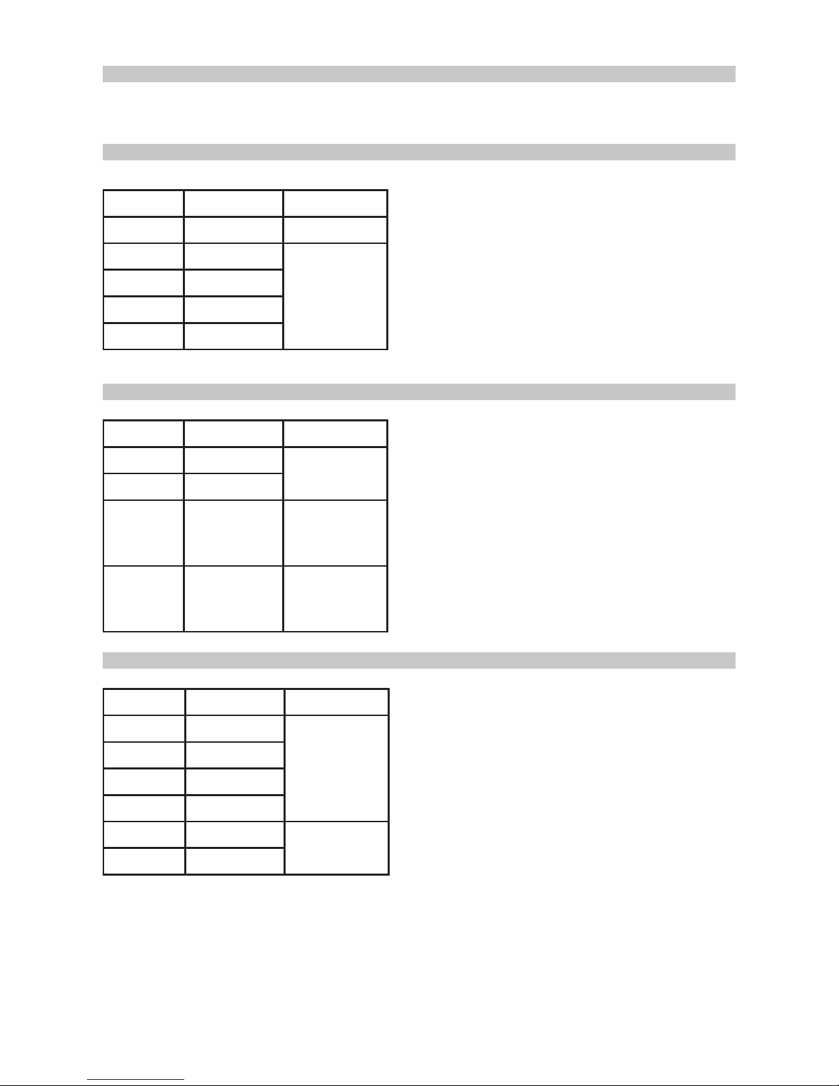
DC VOLTAGE MEASUREMENT
Range Resolution Accuracy
200.0mV 0.1mV ± (0.7% + 5)
2.000V 1mV
± (0.7% + 3)
20.00V 10mV
200.0V 100mV
600V 1V
• Input impedance: approx. 10MΩ.
• As the input impedance on the meter is high,
when measuring a source of lower voltage
and lower impedance (less than 10MΩ), the
measurement may be unstable for a short
time, but will stabilize.
• Warning: Maximum input voltage: ±600V
AC VOLTAGE MEASUREMENT
Range Resolution Accuracy
2.000V 1mV
± (1.0% + 3)
20.00V 10mV
200.0V 100mV
± (1.0% + 3)
VFC mode:
± (4.0% + 3)
600V 1V
± (1.2% + 3)
VFC mode:
± (4.0% + 3)
• Input impedance: approx. 10MΩ.
• Show true virtual value: frequency response:
45~400Hz.
• Accuracy guarantee range: 5-100% range,
short circuit allows <10 residue readings.
• Non-sinusoidal wave counts add error by
crest factor:
- When crest factor is 1~2, add 3%.
- When crest factor is 2~2.5, add 5%.
- When crest factor is 2.5~3, add 7%.
• Warning: Maximum input voltage: 600Vrms.
RESISTANCE MEASUREMENT
Range Resolution Accuracy
200.0Ω 0.1Ω
± (1.0% + 2)
2.000kΩ 1Ω
20.00kΩ 10Ω
200.0kΩ 100Ω
2.000MΩ 1kΩ
± (1.2% + 3)
20.00MΩ 10kΩ
• Range: measured value = measurement
display value - meter pen short circuit value.
• Open circuit voltage is about 1V.
• Overload protection: 600Vrms.
Page 9
9
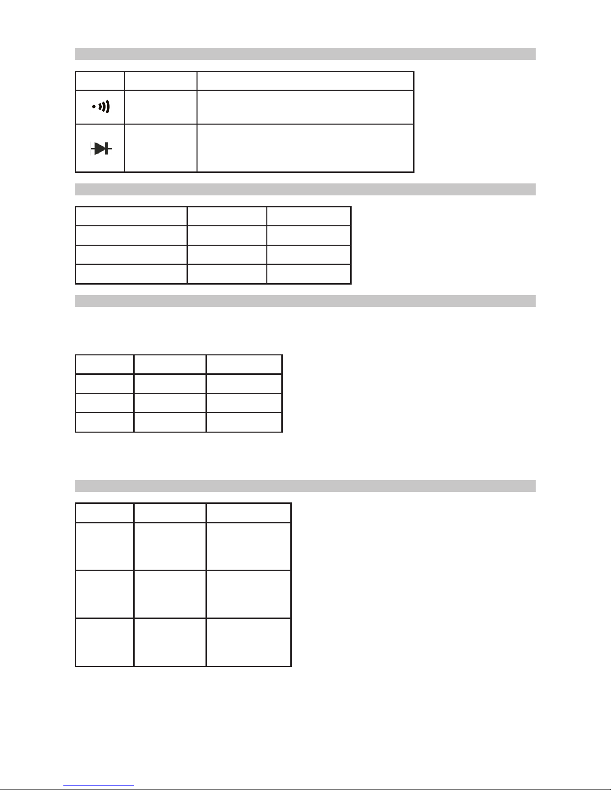
CIRCUIT ON-OFF DIODE MEASUREMENT
Range Resolution Remarks
0.1Ω
Resistance value for circuit disconnect:
>150Ω, buzzer makes no sound.
1mV
Open circuit voltage is 3.2V: normal
voltage for silicon PN junction is
0.5~0.8V.
• Overload protection:
600V rms
CAPACITANCE MEASUREMENT
Range Resolution Accuracy
2nF 1pF ± (4.0% + 10)
20.00nF~200.0µF 10pF~100nF ± (4.0% + 5)
2.000mF~20.00mF 1µF~10µF ± 10%
• Overload protection: 600V rms
• ≤1µF measured capacitance.
It is suggested to use ZERO
measurement mode to ensure
accuracy.
DC CURRENT MEASUREMENT
Range Resolution Accuracy
2.000A 1mA ± (2.0% + 8)
20.00A 10mA ± (2.0% + 3)
100.0A 100mA ± (2.0% + 3)
• Overload protection: 100A.
• Accuracy warranty coverage: 5~100%
range, 2A open circuit allows <20 residue
readings.
• Displays are rms value. Frequency
response: 50~60Hz.
• Non-sinusoidal wave counts add error by
crest factor:
- When crest factor is 1~2, add 3%.
- When crest factor is 2~2.5, add 5%.
- When crest factor is 2.5~3, add 7%.
• Overload protection: 100A.
• Due to the presence of external
electromagnetic elds, press ZERO before
measurement to ensure accuracy of
measurement.
Note: If the reading does not zero after the
initial press, press it several times until the
reading is zero.
• The orientation of the meter during
measurement should be the same as when
zeroed.
AC CURRENT MEASUREMENT
Range Resolution Accuracy
2.000A 1mA
± (3.0% + 10)
VFC mode: ±
(4.0% + 10)
20.00A 10mA
± (2.5% + 8)
VFC mode: ±
(4.0% + 10)
100.0A 100mA
± (2.5% + 5)
VFC mode: ±
(4.0% + 10)
Page 10
10
CLEANING & MAINTENANCE
WARNING: Before removing the rear cover of the instrument, make sure that the meter
is switched off, the meter plugs have been removed from the input port and the lead
disconnected from the circuit under test.
• To clean the instrument, use a clean damp cloth and a mild detergent.
• Do not use any chemicals, abrasives or solvents that could damage the meter.
• If any maintenance is required, refer to qualied personnel.
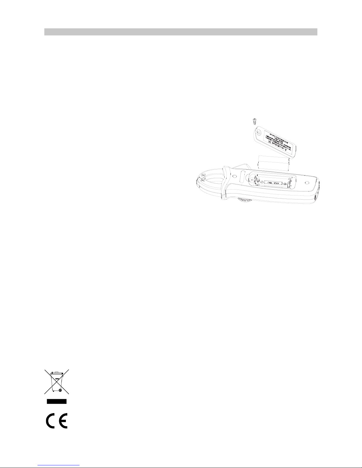
Replacing the Batteries
• When the LCD displays the low battery
symbol, replace the batteries immediately
to preserve measurement accuracy.
• Move the rotary switch to the “OFF”
position and remove the meter plug from
the input jack.
• Unscrew the screw on the rear cover of the
battery and remove the old batteries.
• Replace both batteries with replacements
of the same specication (AAA 1.5V).
INFORMATION ON WASTE DISPOSAL FOR CONSUMERS OF
ELECTRICAL & ELECTRONIC EQUIPMENT.
This symbol indicates that separate collection of Waste Electrical and Electronic
Equipment (WEEE) or waste batteries is required. Do not dispose of these items with
general household waste. Separate for the treatment, recovery and recycling of the
materials used. Waste batteries can be returned to any waste battery recycling point
which are provided by most battery retailers. Contact your local authority for details of
the battery and WEEE recycling schemes available in your area.
Made in China. www.premierfarnell.com
V.1.0
 Loading...