

Tenma 72-14110, 72-14111 User Manual
Function Generator
Model 72-14110 and 72-14111
0

Contents
Function Generator .................................................................................................................................................. 0
Model 72-14110 and 72-14111 ................................................................................................................................. 0
Chapter 1 Safety Information .................................................................................................................................. 3
1.1 Safety Terms and Symbols ..................................................................................................................... 3
1.2 General Safety Overview ........................................................................................................................ 4
Chapter 2 Brief Introduction of Function/Arbitrary Waveform Generator ........................................................... 5
2.1 Main Characteristics ................................................................................................................................... 5
2.2 Introduction of Panels and Keys................................................................................................................ 6
2.2.1 Front Panel ....................................................................................................................................... 6
2.2.2 Back Panel ....................................................................................................................................... 8
2.2.3 Function interface ............................................................................................................................. 9
Chapter 3 Quick Start ............................................................................................................................................. 10
3.1 Handle adjustment .................................................................................................................................... 10
3.2 Basic Waveform Output ............................................................................................................................ 10
3.2.1 Frequency Setting ......................................................................................................................... 10
3.2.2 Amplitude Setting .......................................................................................................................... 11
3.2.3 DC Offset Voltage Setting ............................................................................................................. 11
3.2.4 Square Wave Setting .................................................................................................................... 12
3.2.5 Pulse Wave Setting ...................................................................................................................... 12
3.2.6 DC Voltage Setting ....................................................................................................................... 13
3.2.7 Ramp Wave Setting ..................................................................................................................... 13
3.2.8 Noise Wave Setting ...................................................................................................................... 14
3.3 Frequency Measurement .......................................................................................................................... 14
3.4 Built-in Help System ................................................................................................................................. 15
Chapter 4 Advanced Applications ........................................................................................................................ 16
4.1 Modulation Waveform Output .................................................................................................................. 16
4.1.1 Amplitude Modulation (AM) ............................................................................................................ 16
4.1.2 Modulation Source Selection .......................................................................................................... 24
4.1.3 Frequency Modulation (FM)............................................................................................................ 32
4.1.4 Phase Modulation (PM) .................................................................................................................. 32
4.1.5 Amplitude Shift Keying (ASK) ......................................................................................................... 45
4.1.6 Frequency Shift Keying (FSK) ........................................................................................................ 52
4.1.7 Pulse Width Modulation (PWM) ...................................................................................................... 58
4.2 Sweep Waveform Output .......................................................................................................................... 66
4.2.1 Sweep Selection ............................................................................................................................... 66
4.2.2 Start Frequency and Stop Frequency Setting ................................................................................... 67
4.2.3 Sweep Mode ..................................................................................................................................... 68
4.2.4 Sweep Time ...................................................................................................................................... 68
4.2.5 Trigger Source Selection ................................................................................................................... 69
4.2.6 Trigger Output ................................................................................................................................... 69
1

4.3 Arbitrary Wave Output .............................................................................................................................. 74
4.3.1 Enable Arbitrary Wave Function........................................................................................................ 74
4.3.2 Arbitrary Wave Selection ................................................................................................................... 74
Chapter 5 Fault Handling ....................................................................................................................................... 75
5.1 No Display On Screen (Black Screen) ..................................................................................................... 75
5.2 No Waveform Output ................................................................................................................................ 75
Appendix A Factory Reset State ........................................................................................................................... 76
Appendix B Technical Specifications ................................................................................................................... 79
Appendix C Accessories List ................................................................................................................................ 84
Appendix D Maintenance and Cleaning ............................................................................................................... 85
2
Chapter 1 Safety Informa tio n
1.1 Safety Terms and Symbols
Terms in the manual
The following terms may appear in the manual:
Warning: warning statement, pointing out conditions and behaviors that may endanger life safety.
Caution: cautionary statement, pointing out conditions and behaviors that may cause damage to the product and
other properties.
Terms on the product
The following terms may appear on the product:
Danger: indicate that you may be immediately harmed when reading this sign.
Warning: indicate that you may not be immediately harmed when reading this sign.
Caution: indicate that the product or other properties may be damaged.
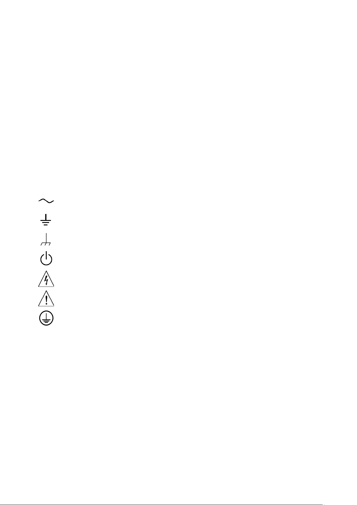
Symbols on the product
The following symbols may appear on the product
Alternating Current
Ground Terminal for Testing
Ground Terminal for Chassis
On/Off Button
High Voltage
Caution! Refer to Manual
Protective Ground Terminal
3

1.2 General Safety Overview
• This instrument is designed and manufactured in compliance with: G84793, lEC61010-1, CAT III 600V,
Pollution Degree 2 and Double Insulation standards.
• When using electrical appliances basi c safety precautions should always be followed.
• Check that the voltage indicated on the rating plate corresponds with that of the local network before
connecting the appliance to the mains power supply.
• Please operate according to this manual, other wise the protection provided by the device will be impaired
or fail.
• This product must be grounded.
• This product is gr ound ed through the ear t h wire in the mai ns l ead. In order to prev ent electric sho ck, p lea se
check whether the power socket to be used for the product is grounded. Please ensure that the protective
ground terminal of the product is reliably connected to the ground terminal of power line before connecting
any input or output terminal.
• This appliance is not intended for use by persons (including children) with reduced physical, sensory or
mental capabilities or la ck of e xperience or knowledge. T hey shou ld be giv en s uperv is ion and instruction in
the use of the appliance by a person responsible for their safety.
• Children should be supervised to ensure that they do not play with the appliance.
• There are no user-serviceable parts in this product. Refer servicing to qualified personnel.
• In order to prevent fire or electric shock, please pay attention to all rated values and modes of the product.
Please read user’s manual before connection of the product to further understand information about rated
values.
• Check the test leads, cables and case insulation before using. If you find any breakage or abnormality, or
you consider the device is broken, stop using the device immediately.
• Do not use the product for any purpose other than that for which it is designed.
• Don’t insert metal objects into input or output terminal of the product.
• If you suspect that the product is damaged, please ask qualified maintenance personnel to inspe ct.
• Never operate the product with the cover removed.
• Do not operate or store in an environment of high humidity or where moisture may enter the product.
• Do not use the meter around explosive gas or vapour.
• Disconnect from the supply when not in use.
4

Chapter 2
Brief Introduction of Tenma Series
Function/Arbitrary Waveform Generator
This device is economical, high-performance, multi-functional single channel waveform generators. It uses direct
digital synthesis (DDS) technology to produce accurate and stable waveforms, with a resolution as low as 1μHz. It
can generate accurate, stable, pure and low distortion output signals; also can provide high-frequency vertical edge
square waves. UTG1000’s convenient interface, superior technical indexes and user-friendly graphical display style
can help users to complete tasks quickly and improve work efficiency.
2.1 Main Characteristics
• Sine wave output of 20MHz/10MHz/5MHz, full frequency range resolution is 1μHz
• Square wave/pulse waveform of 5MHz, and its rising, falling, and duty cycle time are adjustable
• Using DDS implementation method, with 125M/s sampling rate and 14bits vertical resolution
• 6-bit high precision frequency counter that is TTL level compatible
• Arbitrary waveform storage of 2048 points, and it can store up to 16 groups of nonvolatile digital arbitrary
waveforms
• Abundant modulation types: AM, FM, PM, ASK, FSK, PSK, PWM
• Powerful PC software
• 4.3-inch high resolution TFT liquid crystal display
• Standard configuration interface: USB Device
• Supports internal/external modulation and internal/external/manual trigger
• Supports sweep output
• Easy-to-use multifunctional control and number keyboard
5
Terminal
Buttons
13.Function Menu Softkeys
Softkeys
2.2 Introduction of Panels a nd Keys
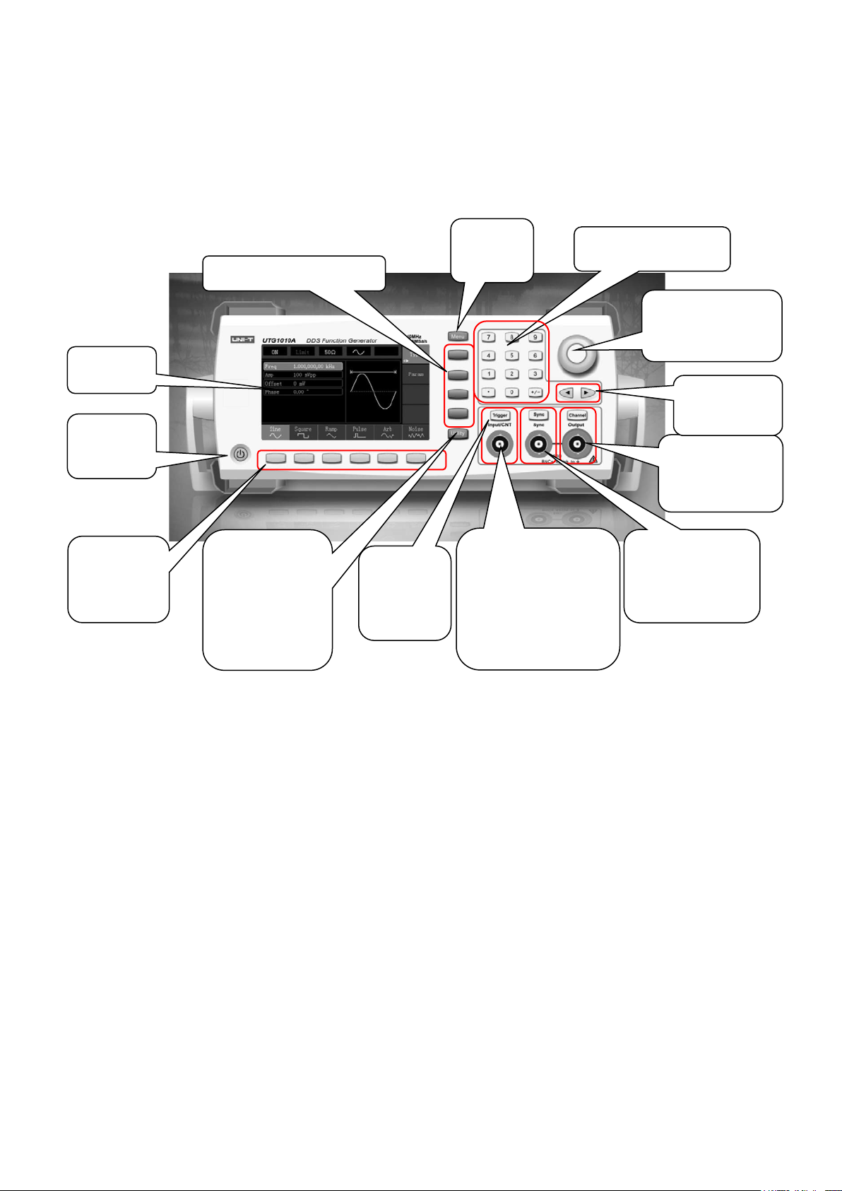
2.2.1 Front Panel
Function/arbitrary w avef orm generator provid es user s with a simple, intuitive, and e asy to o perate fr ont pane l. T he
front panel is shown in figure 2-1:
1.Display
2.On/Off Button
3.Menu
Operation
4. Auxiliary
Function and
System Settings
Buttons
5.Manual
Trigger
Button
12.Menu
Button
6. Modulation/
Frequency Meter
Input Terminal/
Trigger Output
11. Number Buttons
10. Multifunctional
control key
9.Directional
8.CH Control/
Output Terminal
7. Synchronous
Output
Terminal
Figure 2-1 Structure of front panel
1. Display Screen
4.3-inch TFT LCD displays high-reso lution ou tput s tate, f uncti on menu, and ot her i mportant channel i nfor mation. It i s
designed to make human-computer interaction more convenient to improve work efficiency.
2. On/Off Button
To turn on/off the device, press this button and its backlight will turn on (orange), the display will show the function
interface after the boot screen.
3. Menu Operation Softkeys
Correspondingly select or check the label contents by identifications of softkey labels (at the bottom of function
interface).
4. Auxiliary Function and System Settings Button
This button includes 3 function labels: Channel settings, frequency meter, and system. A highlighted label (the
midpoint of the label is gray and font is pure white) has a corresponding sub label at the bottom of the display.
5. Manual Trigger Button
Setting trigger, and carrying out manual trigger when flashing.
6

6. Modulation/Frequency Meter Input Terminal/Trigger Output Terminal
During AM, FM, PM or PWM signal modulation, when modulation source is external, modulation signal is input
through external modulation input. When frequency meter function is on, the signal to be measured is input through
this interface; when manual trigger for channel signal is enabled, manual trigger signal is output through this
interface.
7. Synchronous Output Terminal
This button controls whether open synchronous output or not.
8. CH Control/ Output
Channel output can be turned on/off quickly by pressing Channel button, also can be set by pressing Utility button to
pop-up the label, then pressing the Channel Setting softkey.
9. Direction Buttons
When setting parameters, move left and right to change number bit.
10. Multifunctional Control and Button
Rotate the multifunctional control to change numbers (rotate clockw ise and number s increa se) or use the
multifunctional control as direction button. Press the multifunctional control to select function, set parameters and
confirm selection.
11. Number Keyboard
Number keyboard is used to enter parameter number 0 to 9, decimal point “.” and symbol key “+/-”. Decimal point
can change units quickly.
12. Menu Button
Three function labels will display by pressing the menu button: Waveform, Modulation, and Sweep. Press the
corresponding menu function soft key to access its function.
13. Functional Menu Softkeys
To select function menu options quickly.
7
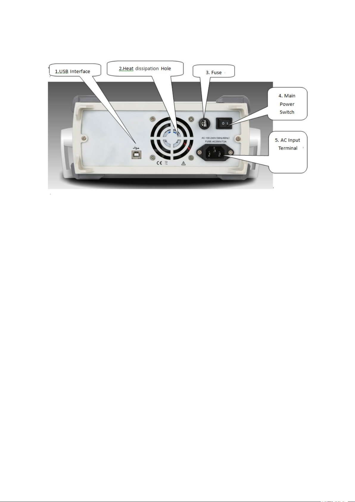
2.2.2 Back Panel
Figure 2-2 Structure of back panel
1. USB Interface
PC software is connected through this USB interface.
2. Heat Dissipation Holes
To ensure this instrument dissipate heat well, please do not block these holes.
3. Protection Fuse
When AC input current is more than 2A, the fuse will cut off the AC input to protect the device.
4. Main Power Switch
Press down on “I” to power the instrument, and press down on “O” to cut off AC input.
5. AC Power Input Terminal
This device supports AC power from 100V to 240V, 45Hz to 440 Hz.
8
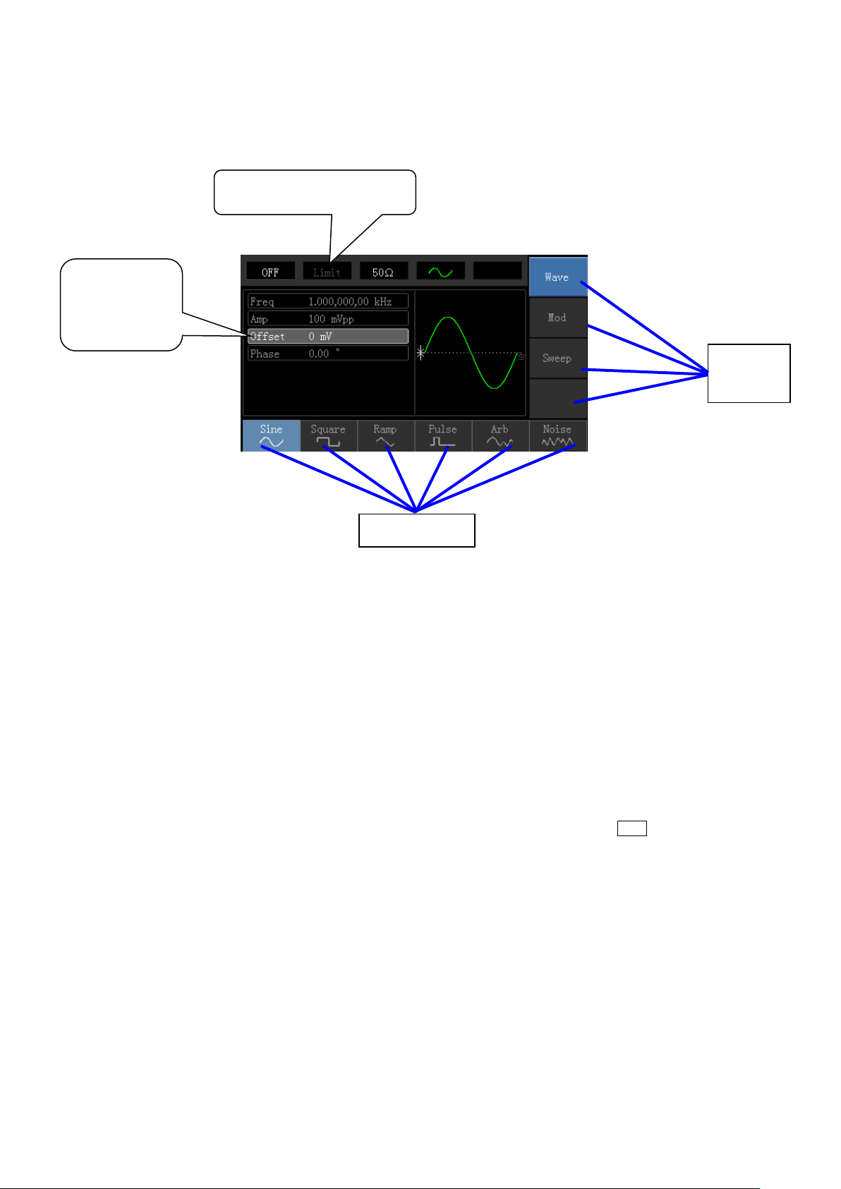
2.2.3 Function interface
List
Softkey Labels
Function interface is shown in figure 2-3:
Waveform
Parameter
Channel Information
Softkey
Labels
Figure 2-3 Function interface
Detailed Description:
Channel information: 1) “ON/OFF” on the left is channel open information. 2) There is a “Limit” logo indicates
output range limit where white is valid and grey is invalid. The matched impedance of output terminal (1Ω to
1KΩ adjustable, or high resistance, factory default is 50Ω). 3) The right side is the current valid waveform.
Softkey labels: Softkey labels are used for identifying menu softkey functions and menu operation softkey
functions.
1) Labels on the right of screen: Highlighted display indicates that the label is selected.
If not, press corresponding softkey to select.
a) Labels at the bottom of screen: Sub label content belongs to the next category of Type label.
Press corresponding button to select sub labels .
Waveform Parameter List: Displays parameters of current waveform in a list.
Waveform Display Area: Displays current channel’s waveform.
9
Chapter 3 Quick Start
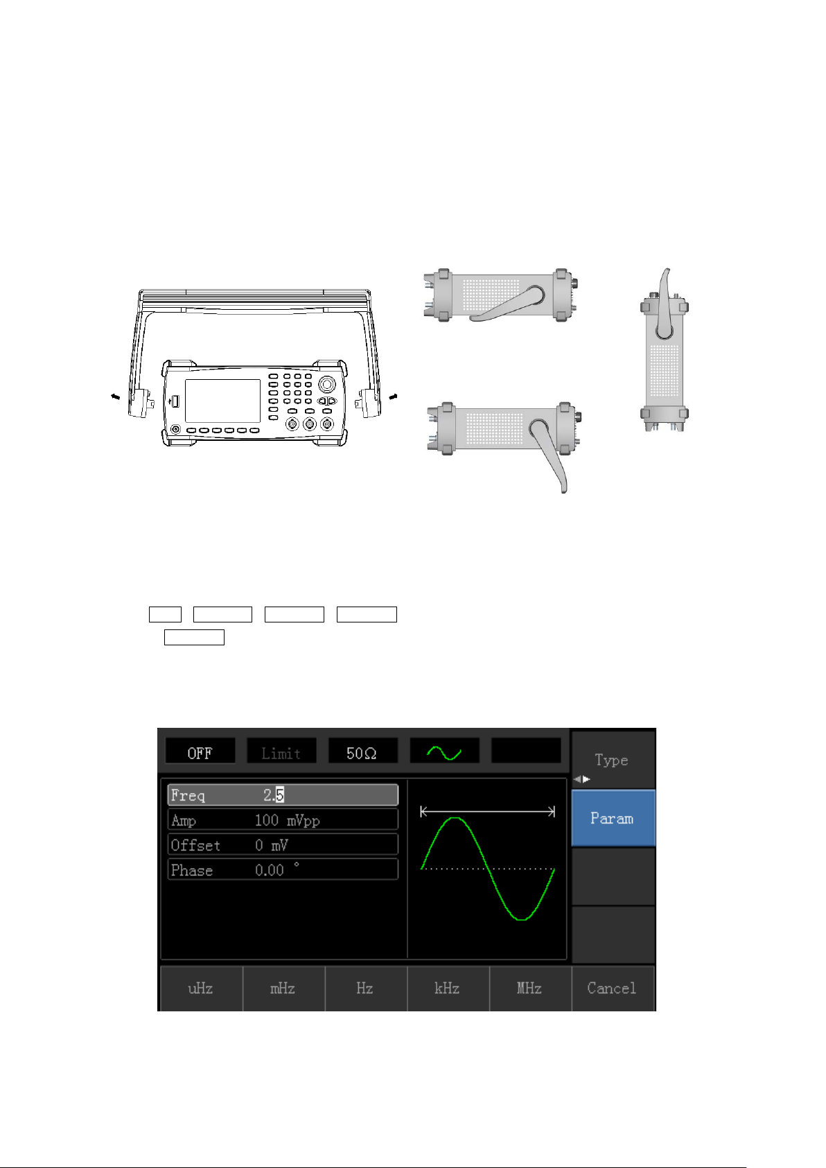
3.1 Handle Adjustment
The Tenma Series F unct ion/Ar bitrary Waveform Gen erator h andle ca n be adj usted to carry and also support the unit .
If the handle positio n needs to be chan ged, p lea se hold the handle o n b oth sides and pull out, then rotate t he han dle
to the desired position, as shown in figure below:
3.2 Basic Waveform Output
3.2.1 Frequency Setting
Default waveform: A sine wave of 1kHz frequency and 100mV amplitude (with 50Ω termination).
For example the specific steps for changing the frequency to 2.5MHz are shown as follows:
a) Press Menu→Waveform→Parameter→Frequency in turn to frequency setting mode. Set parameters by
pressing Frequency softkey to change frequency and period.
b) Use number keyboard to input the required number of 2.5.
c) Select corresponding unit MHz.
10
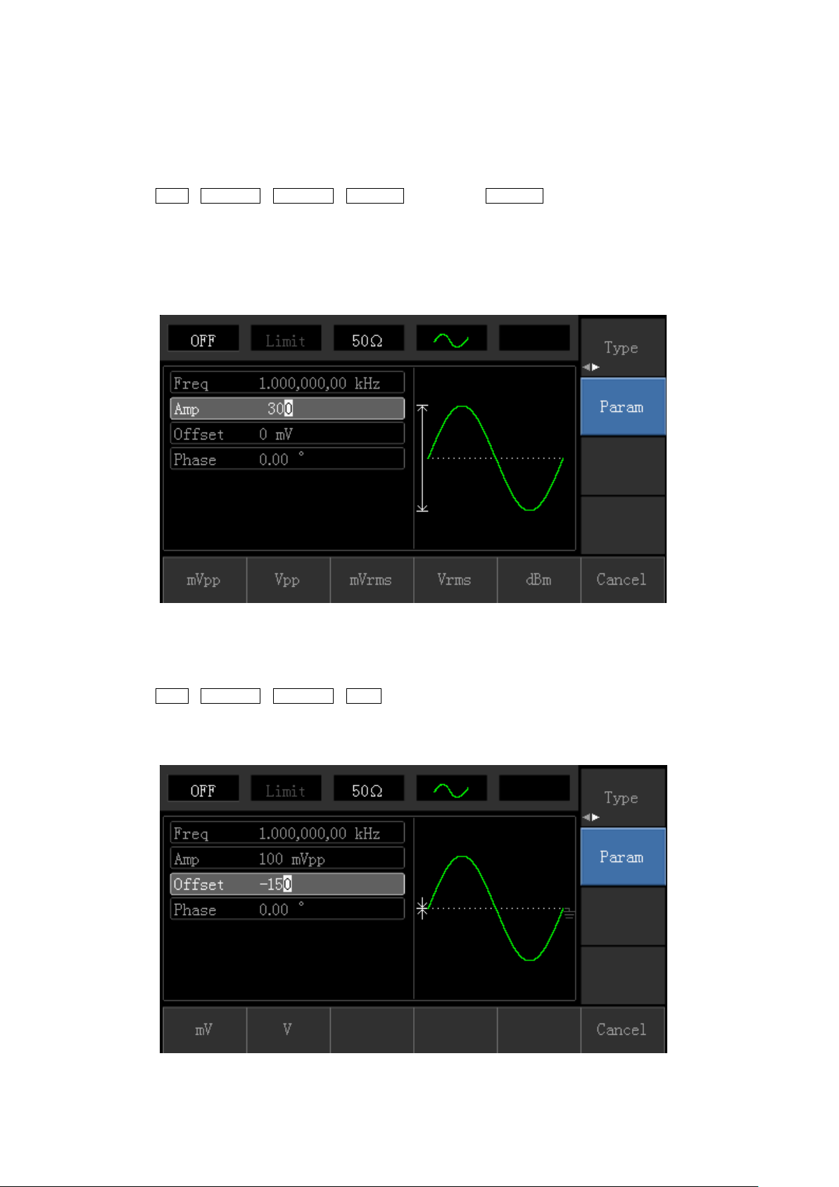
3.2.2 Amplitude Setting
Defaultwaveform: A sine wave of 100mV peak-peak value with 50Ω termination.
Steps for changing the amplitude to 300mV are shown as follows:
1. Press Menu→Waveform→Parameter→ Amplitude in turn. Press Amplitude softkey again can switch between
Vpp, Vrms, and dBm.
2. Use number keys to input 300.
3. Select required unit: Press unit softkeymVpp.
Note: This parameter can be set by multifunctional control and direction buttons.
3.2.3 DC Offset Voltage Setting
The default waveform is a sine wave with 0V DC offset voltage (with 50Ω termination).
Steps for changing DC offset voltage to -150mV are shown as follows:
1. Press Menu→Waveform→Parameter→ Offset to enter parameter setting.
2. Use number keys to input the required number of -150.
3. Select corresponding unit mV.
Note: This parameter can be set by multifunctional control and direction buttons.
11
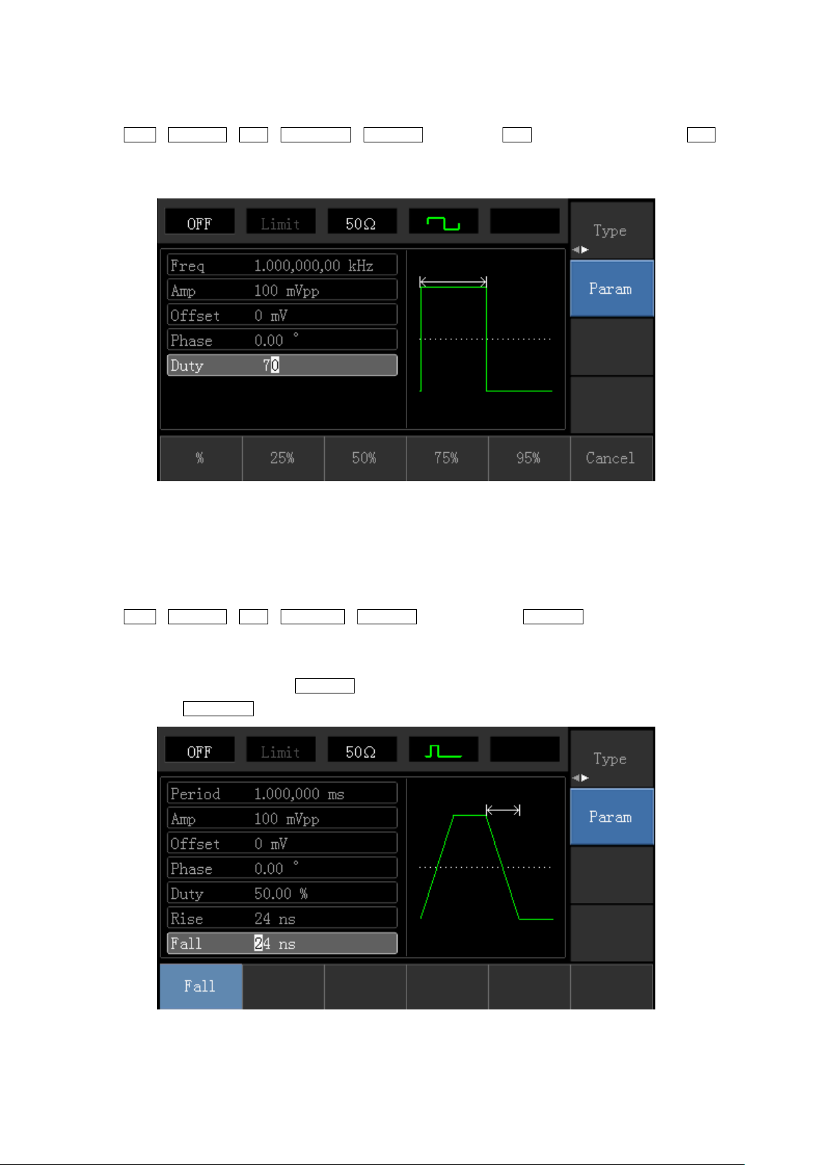
3.2.4 Square Wave Setting
Press Menu→Waveform→Type→Squarewave→Parameter in turn (press Type softkey to select only when Type
label is not highlighted) . I f par a meter need s to be set, press correspond ing softkey to enter required numerical value
and select the unit.
Note: This parameter can be set by multifunctional control and direction buttons.
3.2.5 Pulse Wave Setting
Default duty cycle of pulse wave is 50% and rising/falling edge time is 1us.
Steps for setting square wave with 2ms period, 1.5Vpp amplitude, 0V DC offset and 25% duty cycle (limited
by the minimum pulse width specification 80ns), 200us rising time and 200us falling time are as follows:
Press Menu→Waveform→Type→PulseWave→Parameter in turn, then press Frequency softkey to switch to
Period. Enter requir ed nu mber value and select the unit. When ent erin g dut y cycle v alue, there is a qui ck la bel at the
bottom of display, and select 25%.
If need to set falling edge time, press Parameter softkey or rotate multifunctional control to the right to enter sub
label, then press Falling Edge softkey to enter required number and select unit.
Note: This parameter can be set by multifunctional control and direction buttons.
12
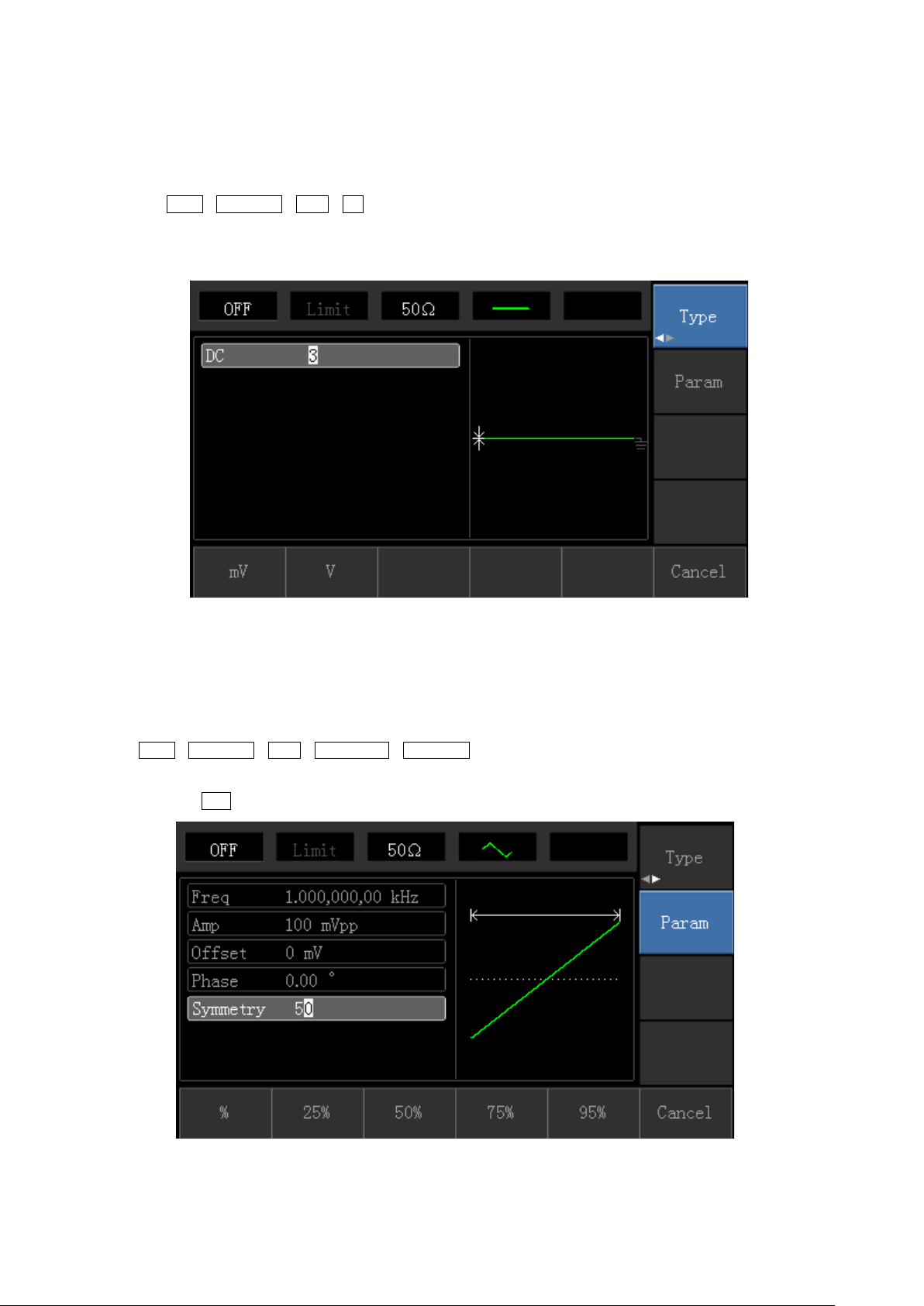
3.2.6 DC Voltage Setting
DC voltage output is the setting of DC offset on powering on.
Steps for changing DC offset voltage to 3V are seen as follows:
1. Press Menu→Waveform→Type→DC in turn to enter parameter setting mode.
2. Use number keyboard to input the required number of 3.
3. Select required unit V
Note: This parameter can be set by multifunctional control and direction buttons.
3.2.7 Ramp Wave Setting
Default symmetry degree of ramp wave is 100%.
Steps for setting triangular wave with 10kHz frequency, 2V amplitude, 0V DC offset and 50% duty cycle
are shown as follows:
Press Menu→Waveform→Type→RampWave→Parameter in turn to enter parameter setting mode. Select
parameter to enter edit mode, then input required numbers and select unit. Note: When enter symmetry degree
value, there is a 50% label at the bottom of display, press corresponding softkey or use number keyboard.
Note: This parameter can be set by multifunctional control and direction buttons.
13
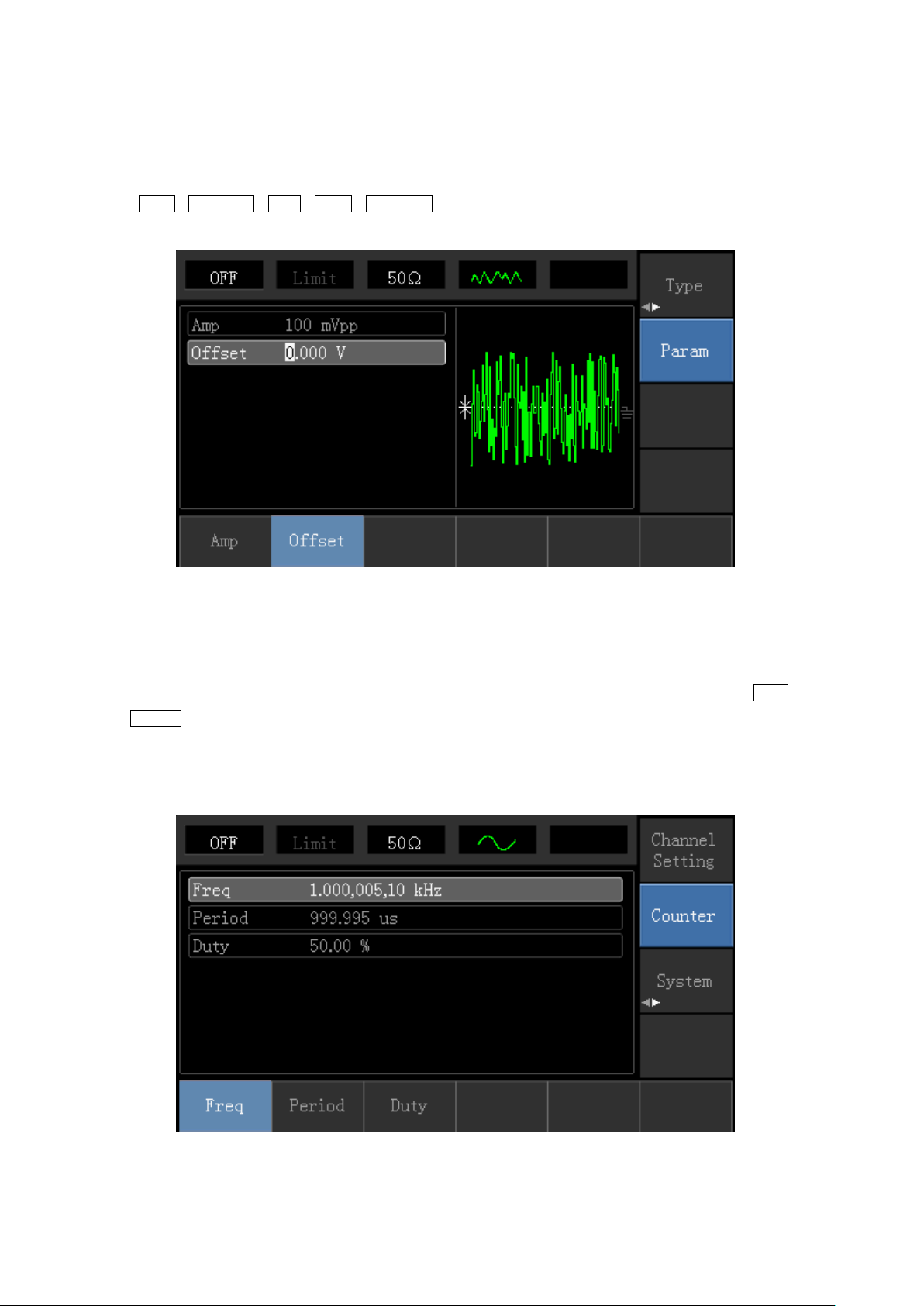
3.2.8 Noise Wave Setting
Default Quasi Gauss noise amplitude is 100mVpp and DC offset is 0mV.
Steps for setting Quasi Gauss noise with 300mVpp amplitude and 1V DC offset are shown as follows:
Press Menu→Waveform→Type→Noise→Parameter in turn to enter parameter editing mode. After setting, enter
required number and unit.
Note: This parameter can be set by multifunctional control and direction buttons.
3.3 Frequency Measurement
This device is suitable for measuring frequency and duty cycle of TTL compatible signals, with frequency range of
1Hz to 100MHz. The frequency meter takes signal through the input interface (Input/CNT terminal). Press Utility
then Counter to collect Frequency, Period, and Duty Cycle values from input signal. Note: When there is no signal
input, frequency meter parameter list always shows last measurement value. Frequency meter will refresh only
when new TTL compatible signal is present at the Input/CNT terminal.
14

3.4 Built-in Help System
The built-in help system provides relevant information for any button or menu softkey. You also can use help topic
list to get help. Operations for buttons help information are shown as following:
Long press any softkey or button to display relevant information. If the content is more tha n 1 screen size, use
softkey or multifunctional control to display the next screen. Press “Return” to exit.
Note!
The built-in help system provides simplified Chinese and English languages. All information, context help and help
topic are displayed in selected language. Language setting: Utility→ System→Language.
15
Chapter 4 Advanced Applications
4.1 Modulation Waveform Out put
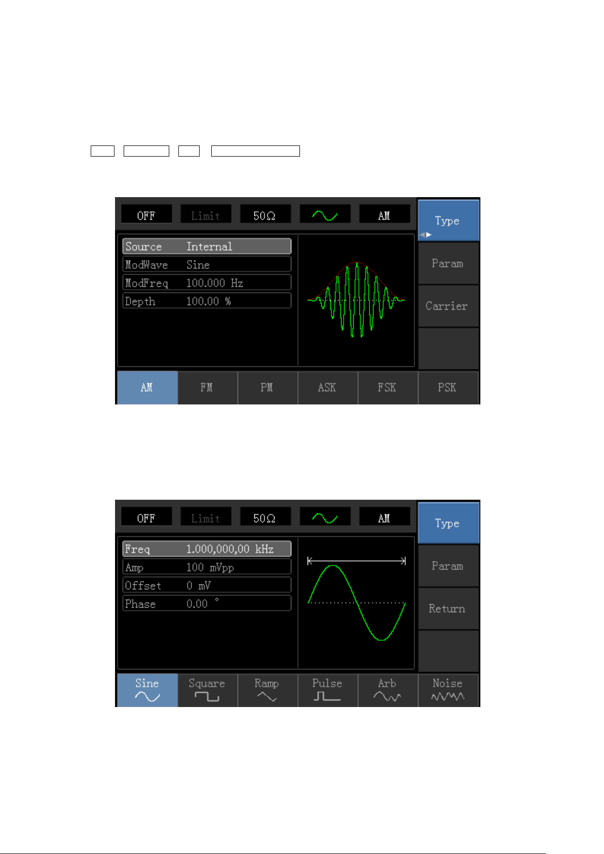
4.1.1 Amplitude Modulation (AM)
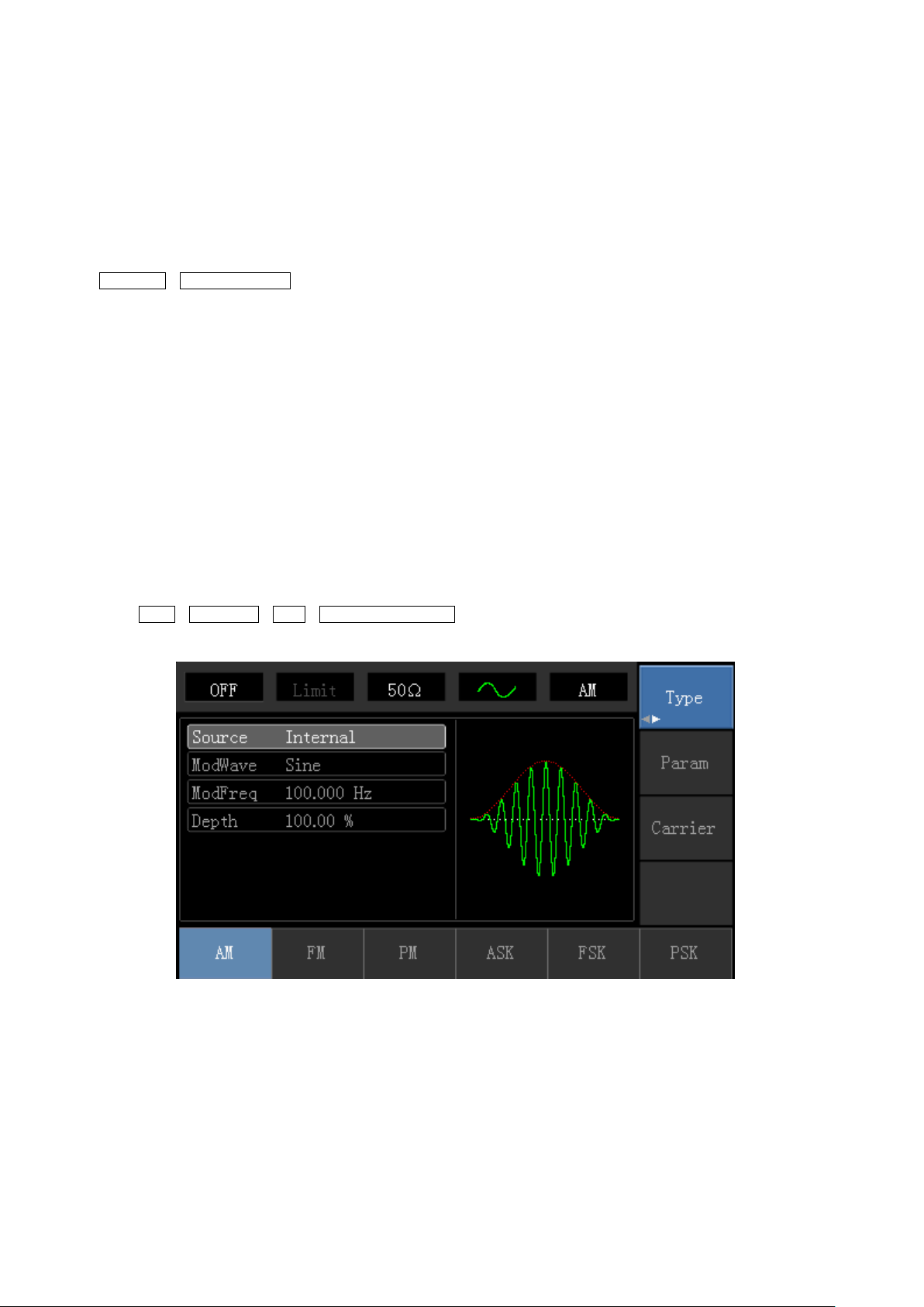
Press Menu→Modulation→Type→ Amplitude Modulation in turn to start the AM function. Then the modulated
waveform will output with modulation waveform and carrier wave set.
Select carrier waveform
AM carrier waveform can be: sine wave, square wave, ramp wave or arbitrary wave (except DC), and the default is
sine wave. After sele cting AM modu lation, pre ss Carr ier Wave Para meter softkey to en ter carrier w av eform sel ection
interface.
16

Carrier Wave Frequency Setting
Settable carrier wave frequency range is different for different carrier waveforms. Default frequency of all carrier
wave is 1kHz. The frequency setting range of each carrier wave can be seen in the following table:
Frequency
Carrier
Wave
Minimum Value Maximum Value Minimum Value Maximum Value
Sine Wave 1μHz 10MHz 1μHz 5MHz
UTG1010A UTG1005A
Square
wave
Ramp
Wave
Arbitrary
Wave
To set carrier frequency, please press Parameter→ Frequency softkey, then enter required numerical value, and
select unit after selecting carrier waveform.
Modulation Source Selection
This device can select internal modulation source or external modulation source. After enabling AM function, the
default modulation source is internal . If need to chan ge pres s Parameter→ModulationSource→External in turn.
1μHz 5MHz 1μHz 5MHz
1μHz 400kHz 1μHz 400KHz
1μHz 2MHz 1μHz 1MHz
17
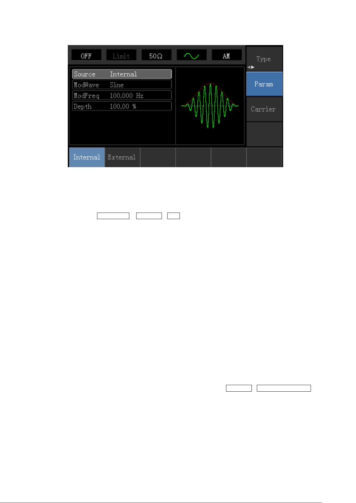
1) Internal Source
When modulation source is internal, modulation wave can be: sine wave, square wave, rising ramp wave, falling
ramp wave, arbitrary wave and noise. After enabling AM function, the default of modulation wave is sine wave. If
need to change it, press Carrier Wave →Parameter→Type in turn.
Square wave: duty cycle is 50%
Rising Ramp Wave: symmetry degree is 100%
Falling Ramp Wave: symmetry degree is 0%
Arbitrary Wave: when arbitrary wave is modulated waveform, DDS function generator limits arbitrary wave
length as 1kpts in the way of random selection
Noise: White Gauss noise
2) External Source
When modulation source is external, parameter list will hide the modulation wave option and modulation frequency
option, and carrier waveform will be modulated by an external waveform. AM modulation depth is controlled by ±5V
signal level of external modulation input terminal. For example, if modulation depth value is set to 100%, AM output
amplitude is the maximum when external modulation signal is +5V, AM output amplitude is the minimum when
external modulation signal is -5V.
Modulation Shape Frequency Setting
When modulation source is internal, frequency of modulation shape can be modulated. After enabling AM function,
range of modulation wave frequency is 2mHz~50kHz (default is 100Hz). Press Parameter→Modulation Frequency
to change. When modulati on s ource is external, parameter l ist w ill hide t he mod ulat ion sha p e opt i on a nd modu lat ion
frequency option, and carrier waveform will be modulated by an external waveform. The range of modulation signal
input from external is 0Hz~ 20Hz.
18
Modulation Depth Setting
Modulation depth indicates the extent of amplitude variation and is expressed as percentage. Suitable setting range
of AM modulation depth is 0% to 120%, and the default is 100%. When modulation depth is set to 0%, the constant
amplitude (a half of the carrier wave amplitude that has been set) is output. Output amplitude changes as
modulation waveform changes when modulation depth is set to 100%. The instrument output a peak-peak voltage
less than ±5V (is connected with 50Ω terminal) when modulation depth is more than 100%. If need to change, press
Parameter→Modulation Depth in amplitude function interface. When modulation source is external, output
amplitude of the instrument is controlled by ±5V signal level of external modulation input terminal (Input/CNT probe)
in rear panel. For example, if modulati on depth value in par a meter list has been s et to 100%, AM output a mpl itude is
the maximum when external modulation signal is +5V, AM output amplitude is the minimum when external
modulation signal is -5V.
Comprehensive Example
Firstly, make the instrument work in amplitude modulation (AM) mode, then set a sine wave with 200Hz from the
internal of the instrume nt as a modulati on sign al and a s quar e wav e with frequency of 10kHz, amplitude of 200mVp p
and duty cycle of 45% as a carrier wave signal. Finally, set modulation depth to 80%. Specific steps are seen as
following:
1) Enable Amplitude Modulation (AM) Function
Press Menu→Modulation→Type→Amplitude Modulation in turn.
19

2) Set Modulation Signal Parameter
After enabling the AM function, press Parameter softkey and the interface will appear as following:
Press corresponding softkey, then enter required numerical value, and select the unit.
3) Set Carrier Wave Signal Parameter
Press Carrier Wave Parameter→Type→ Square Wave in turn to select square wave as carrier wave signal.
20
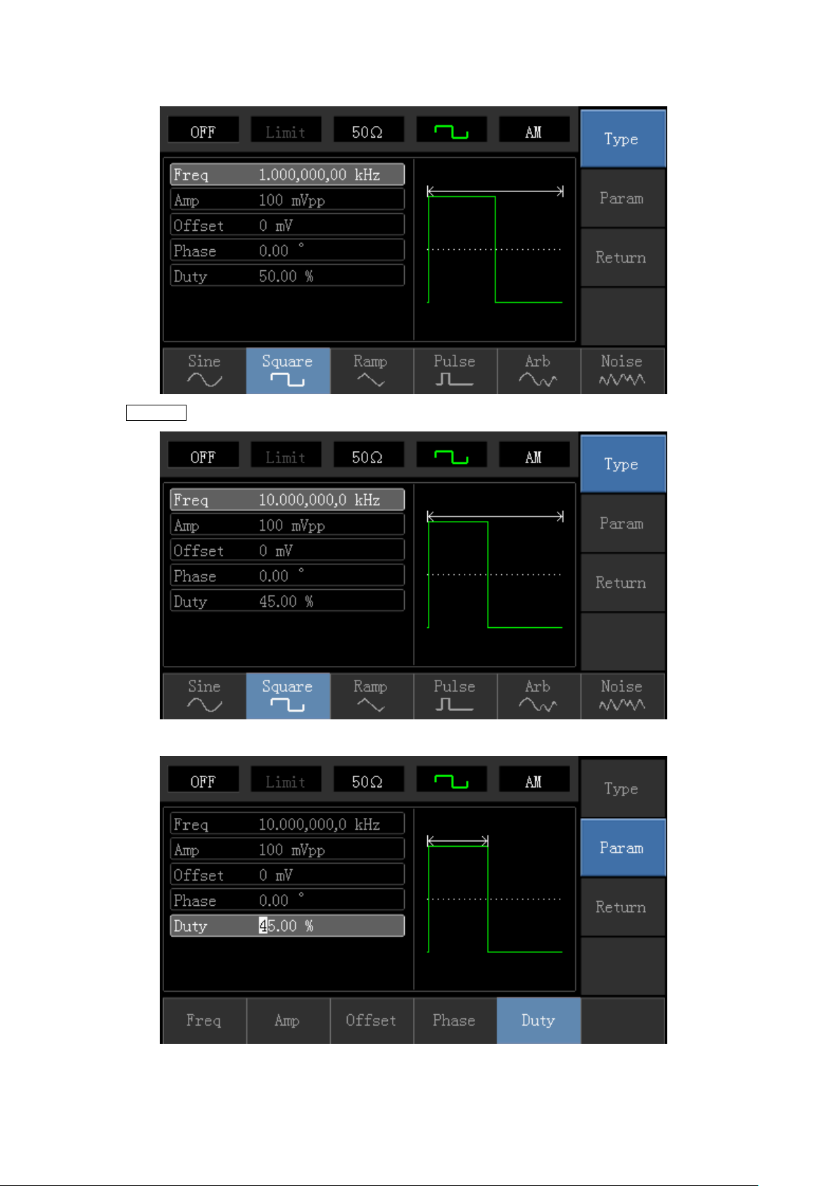
Press Parameter softkey again, and the interface will pop up as following:
Press corresponding softkey, then enter required numerical value, and select the unit.
21
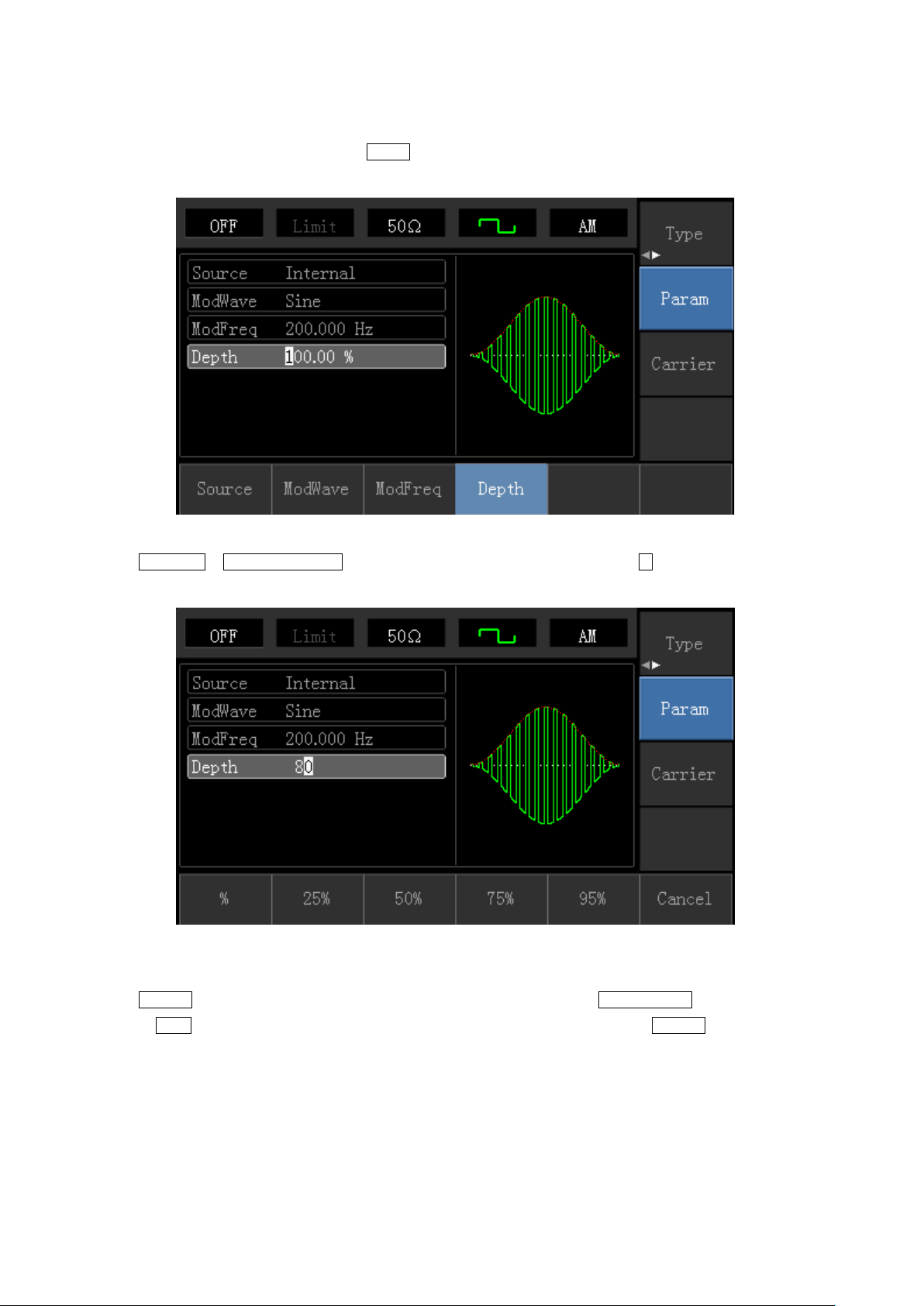
4) Set Modulation Depth
After setting carrier wave parameter, press Return softkey to back to the following interface for setting modulation
depth.
Press Parameter →Modulation Degree softkey again, then enter number 80 and press % softkey with number
keyboard for setting modulation depth.
5) Enable Channel Output
Press Channel button start channel output quickly. Or enable output by pressing Channel Setup softkey after
pressing Utility button and popping up labels. Aft er ch anne l o utput is opened, backlight of Channel button is on, and
on the right side of channel information label, the font “OFF” changes to “ON”, meaning open channel output.
22
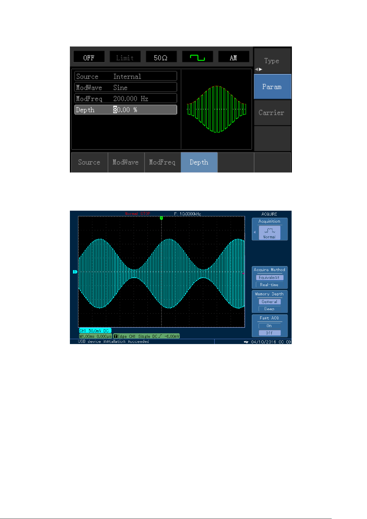
The shape of AM modulation waveform checked through oscilloscope is shown as following:
23
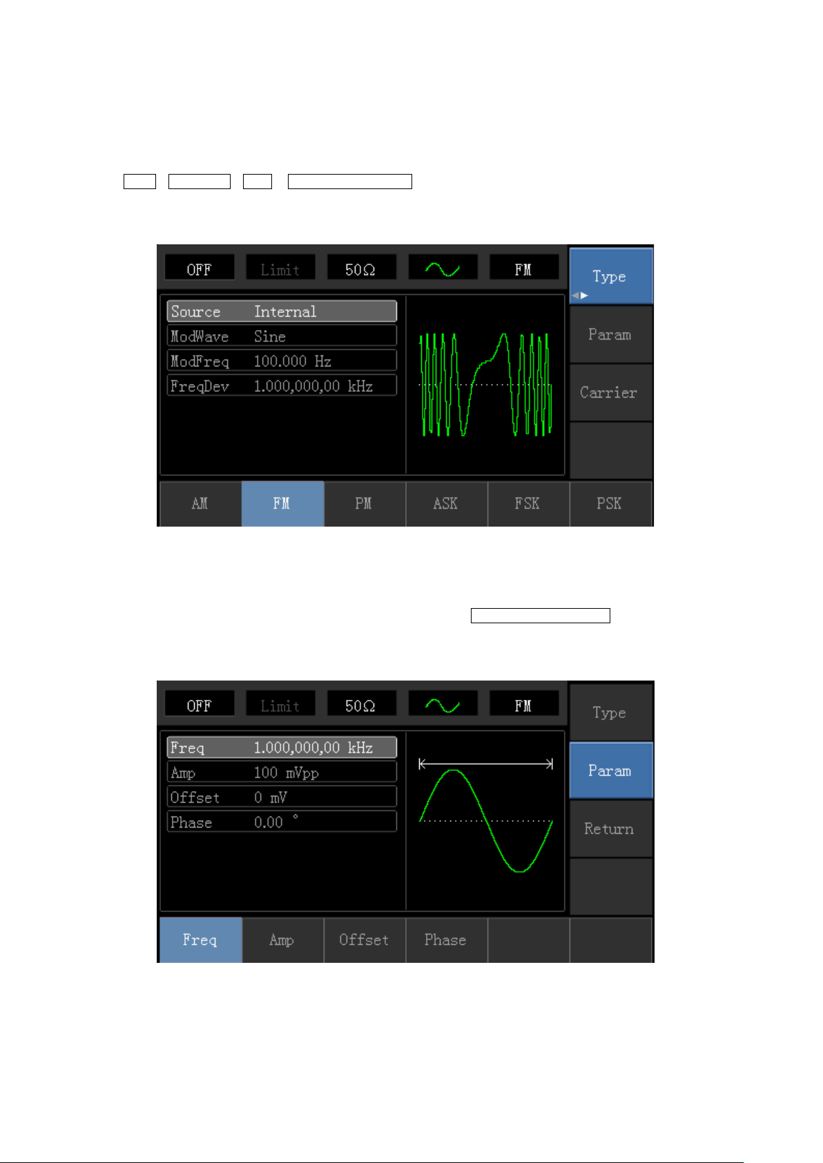
4.1.2 Frequency Modulation (FM)
In frequency modulation, modulated waveform is usually composed of carrier wave and modulation shape. Carrier
wave frequency will change as the amplitude of modulation shape changes.
Press Menu→Modulation→Type→ Frequency Modulation in turn to start the FM function. The device will output
modulated waveform with modulation waveform and carrier wave set currently.
Carrier Wave Waveform Selection
FM carrier waveform can be: Sine wave, square wave, ramp wave, pulse wave, arbitrary wave (except DC) and
noise (the default is sine wave). After selecting FM modulation, press Carrier Wave Parameter softkey to enter
carrier waveform selection interface.
24

Carrier Wave Frequency Setting
Settable carrier wave frequency range is different of different carrier waveform. Default frequency of all carrier wave
is 1kHz. The frequency setting range of each carrier wave can be seen in the following table:
Carrier
Wave
Waveform
Sine Wave 1μHz 10MHz 1μHz 5MHz
Square
wave
Ramp
Wave
Arbitrary
Wave
Press Parameter→Frequency softkey in turn to set carrier wave frequency, then enter required numerical value,
and select unit.
Modulation Source Selection
This device can select internal modulation source or external modulation source. After enabling FM function, the
default of modulation source is internal. If need to change, press
Frequency
72-14111 72-14110
Minimum Maximum Minimum Maximum
1μHz 5MHz 1μHz 5MHz
1μHz 400kHz 1μHz 400KHz
1μHz 2MHz 1μHz 1MHz
1) Internal Source
When modulation source is internal, modul atio n w ave can be: sine wave, square wave, rising ramp wave, falling
ramp wave, arbitrary wave and noise. After enabling FM function, the default of modulation wave is sine wave. If
need to change, press Carrier Wave →Parameter→ Type in turn.
25
 Loading...