

Page 1
DC Electronic Load Power Supply User Manual
Model No.72-13200 and 72-13210
1
Page 2

When using electrical appliances, basic safety precautions should always
be followed to reduce the risk of re, electric shock and injury to persons or
property.
Read all instructions before using the appliance and retain for future reference.
• Check that the voltage indicated on the rating plate corresponds with that of the
local network before connecting the appliance to the mains power supply.
• Do not operate this appliance with a damaged plug or cord, after a malfunction or
after being dropped or damaged in any way.
• Check the product before use for any damage. Should you notice any damage on
the cable or casing, do not use.
• This appliance contained no user-serviceable parts. All repairs should only be
carried out by a qualied engineer. Improper repairs may place the user at risk of
harm.
• Do not block or obstruct the cooling fan vent opening.
• Avoid severe impacts or rough handling that leads to damage.
• Do not discharge static electricity.
• This appliance can be used by children aged from 8 years and above and persons
with reduced physical, sensory, or mental capabilities or lack of experience and
knowledge if they have been given supervision or instruction concerning use of the
appliance in a safe way and understand the hazards involved.
• Children should be supervised to ensure that they do not play with the appliance.
• Always disconnect from the mains when the product is not in use or before
cleaning.
• Do not use the appliance for any purpose other than that for which it is designed.
• Do not operate or store in an environment of high humidity or where moisture may
enter the product as this can reduce insulation and lead to electric shock.
PRODUCT OVERVIEW
Main Features
• High accuracy/resolution 0-120V DC power supply
• 0.1mV/0.1mA overvoltage protection
• Constant voltage/constant current
• Four modes CV/CC/CR/CW
• Digital panel control - 5 digit LED display
• Battery test function
• External trigger function
• Remote compensation function
• Input adjustment lock
• Power off 100 group memory function
• Standard interfaces: USB, RS232 & LAN
WHAT’S INCLUDED
• Power Supply Unit
• Mains power lead
• User Manual
2
Page 3
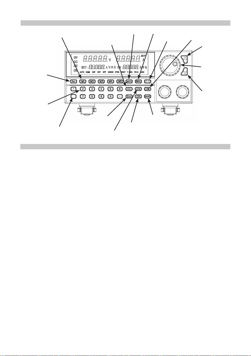
OPERATION
M1-M5 Steady State Stored Value
Constant Current
Mode button
Shift key
Call/Recall key
Adjuster Key
Constant Power
Mode button
Adjustment
Up
Rotary
Esc/Cancel key
input
selector
Adjustment
Down
Numerical Input
buttons
On/Off load output
Shift key
Conrmation button
Constant resistance mode button
Constant Voltage Mode button
STEADY STATE FUNCTION MODES
• The electronic load can work in the following 4 steady-state modes.
Constant Current Operation Mode CC
Note: In constant current mode, the load holds the tested equipment on the set current
no matter how the input voltage changes.
• Operation Method:
1. Press the CC button on the
panel
to enter constant current operation mode.
2. Set the desired constant current through the numerical buttons
3. Press ENTER to conrm.
4. Press the ON/OFF button to start the electronic load.
Constant Voltage Operation Mode CV
Note: In constant voltage mode, the load holds the tested equipment on the set voltage
no matter how the input current changes.
• Operation Method:
1. Press the CV button on the panel to enter constant voltage operation mode
.
2. Set the desired constant current through the numerical buttons.
3. Press ENTER to conrm.
4. Press the ON/OFF button to start the electronic load.
Constant Resistance Operation Mode CR
Note: In constant resistance mode, the load holds the tested equipment on the set
resistance no matter how the input voltage and current change.
• Operation Method:
1. Press the CR button on the panel to enter constant voltage operation mode.
2. Set the desired constant current through the numerical buttons.
3. Press ENTER to conrm.
4. Press the ON/OFF button to start the electronic load.
3
Page 4

Constant Power Operation Mode CW
Note: In constant power mode, the load holds the tested equipment on the set wattage
no matter how the input voltage and current change.
• Operation Method:
1. Press the CW button on the panel to enter constant voltage operation mode.
2. Set the desired constant power through the numerical buttons.
3. Press ENTER to conrm.
4. Press the ON/OFF button to start the electronic load.
Note: Values for all inputs can be entered using either the rotary input selector, up or
down buttons or number keys in all modes.
Setting the maximum values of a load
• Setting low voltage (18V), low current (3A) and below will improve the accuracy.
Example: Setting the max current to 3A, max voltage to 18V and max power to 100W,
and the max resistance to 1000ohms.
1. Press SHIFT+CV to enter settings mode.
2. Set the required current (3A) value and press ENTER.
3. Press CV to enter next input mode.
4. Set the required voltage (18V) and press ENTER.
5. Press CV to enter next input mode.
6. Set the required power (100W) and press ENTER.
7. Press CV to enter next input mode.
8. Set the desired resistance (1000Ω) and press ENTER.
9. Press ESC to complete and enter steady mode. The steady mode status is
displayed.
Storing steady state values and recalling from memory
Note: The memory can save and recall 100 sets of steady mode settings.
• Once a set of values are input press SHIFT+2 to enter memory storage mode.
• Each location can be saved as a numerical identier 1-100.
• Press ENTER to store the location.
Restoring steady state values from memory
Press CALL+2 to enter memory storage mode.
• Select the location of the stored values required from 1-100.
• Press ENTER to recover the saved values.
Quick access steady state value memory
For commonly used values there are 5 quick access and storage buttons.
• Once a set of values are input press button M1 to M5 to store the settings.
• To recover the required saved settings instantly, press M1 to M5.
Short circuit function
Note: the load will make the tested equipment output the max current.
• Press SHIFT+7 to enter the short circuit test mode.
4
Page 5

Dynamic test function
There are 6 settings, Dynamic CV, Dynamic CC, Dynamic CR, Dynamic CW, Dynamic
Pulse and Dynamic Flip. There are no memory storage functions for these.
Dynamic CV (CR and CW modes similar sequence)
• Press SHIFT+ENTER to enter the dynamic setting mode.
• Press 1 then press ENTER to enter the setting mode.
1. Set the required rst voltage and press ENTER.
2. Set the required second voltage then press ENTER.
3. Set the required frequency then press ENTER.
4. Set the required duty cycle percentage and press ENTER to nish.
• Press the ON/OFF button to start or pause.
• The LED display on the lower left displays the count.
Note: Dynamic CR selects mode 3 while Dynamic CW selects mode 4.
To use Dynamic CR or Dynamic CW choose setting values of resistance or power.
Dynamic CC
• Press SHIFT+ENTER to enter the dynamic setting mode.
• Press 2 then press ENTER to enter the setting mode.
1. Set the required rst current change rate and press ENTER.
2. Set the required second current change rate then press ENTER.
3. Set the required rst current then press ENTER.
4. Set the required second current and press ENTER.
5. Set the required rst duty cycle and press ENTER.
6. Set the required second duty cycle setting and press ENTER to nish.
• Press the ON/OFF button to start or pause.
• The LED display on the lower left displays the count.
Dynamic Pulse
Note: Initially the rst setting current is used and the load will switch to the second
setting current on receiving a trigger. After maintaining the setting time, it will switch
back to the rst current. Press SHIFT+ENTER to enter the dynamic setting mode.
• Press 5 then press ENTER to enter the setting mode.
1. Set the required rst current change rate and press ENTER.
2. Set the required second current change rate then press ENTER.
3. Set the required rst current then press ENTER.
4. Set the required second current and press ENTER.
5. Set the required pulse width setting and press ENTER to nish.
• Press the ON/OFF button to start or pause. Press button 3 to trigger once only.
5
Page 6

Dynamic Toggle
Initially the rst setting current is used and the load will switch to the second setting
current on receiving a trigger. After maintaining the setting time, it will switch back to the
rst current.
• Press SHIFT+ENTER to enter the dynamic setting mode.
• Press 6 then press ENTER to enter the setting mode.
1. Set the required rst current change rate and press ENTER.
2. Set the required second current change rate then press ENTER.
3. Set the required rst current then press ENTER.
4. Set the required second current and press ENTER to nish setting.
• Press the ON/OFF button to start or pause. Press button 3 to trigger once only.
Sequential Operation Function
7 locations can be stored in memory and each can have up to 84 dynamic currents. The
current can be cycled through in sequence.
• Press SHIFT+CC to enter the dynamic setting mode.
• Enter location 1 to 7 then press ENTER to enter the memory storage mode.
1. Set the required max current and press ENTER.
2. Set the rst dynamic change current value and press ENTER.
3. Set the change rate and press ENTER.
4. Set the sequence time and press ENTER
5. Set the second dynamic change current value and press ENTER.
6. Set the change rate and press ENTER.
7. Set the sequence time and press ENTER
8. Set the third dynamic change current value and press ENTER.
9. Set the change rate and press ENTER.
10. Set the sequence time and press ENTER
11. Set the number of repetitions and press ENTER to store the settings.
12. Press ESC button to exit the input mode.
• To use the settings press ON/OFF to start or pause.
Note: Pressing ESC after entering an incorrect value will erase the entry allowing you to
repeat the value again before pressing ENTER to store.
Sequential Recall Function
Use to recall any of the 7 stored sequential operation in memory.
• Press CALL+CC to enter the recall function mode.
• Enter location 1 to 7 as required.
• The sequential setting will be displayed on the LED readout.
• To use the settings press ON/OFF to start or pause.
• When the number of repetitions is complete, press ON/OFF to repeat.
• The LED display on the lower left displays the repetition count.
6
Page 7

Battery Test Function
Up to 10 test settings can be stored in memory.
• Press SHIFT+6 to enter the battery test mode.
• Enter location 1 to 10 then press ENTER to enter the memory storage mode.
1. Set the current rate and press ENTER.
2. Set the discharge current and press ENTER
3. Set the discharge end-off voltage and press ENTER.
4. Set the discharging end-off capacity and press ENTER.
5. Set the discharging end-off time and press ENTER to store the settings.
6. Press ESC button to exit the input mode.
Note: Pressing ESC after entering an incorrect value will erase the entry allowing you to
repeat the value again before pressing ENTER to store.
Battery Test Recall Function
Use to recall any of the 10 stored battery test operations in memory.
• Press CALL+6 to enter the recall function mode.
1. Enter location 1 to 10 as required.
2. To use the settings press ON/OFF to start or pause.
• When the testing parameters are reached, the test will be terminated automatically.
Over Current Protection Test Function
Up to 10 test settings can be stored in memory.
• Press SHIFT+9 to enter the OCP test function mode.
• Enter location 1 to 10 then press ENTER to enter the memory storage mode.
1. Set the VON voltage and press ENTER.
2. Set the VON time delay and press ENTER
3. Set the current range and press ENTER.
4. Set the start current and press ENTER.
5. Set the step current and press ENTER.
6. Set the step reduction time and press ENTER.
7. Set the end current and press ENTER.
8. Set the OCP voltage and press ENTER.
9. Set the maximum current and press ENTER.
10. Set the minimum current and press ENTER to store the settings.
11. Press ESC button to exit the input mode.
• To use the settings press ON/OFF to start or pause.
• The LED display on the lower right displays the trigger count.
Note: Pressing ESC after entering an incorrect value will erase the entry allowing you to
repeat the value again before pressing ENTER to store.
7
Page 8

Over Current Protection Test Recall Function
Use to recall any of the 10 stored OCP test values in memory.
• Press SHIFT+9 to enter the OCP recall function mode.
• Enter location 1 to 10 as required.
• To use the settings press ON/OFF to start or pause.
• When one of the conditions is met the output will cease, press ON/OFF to repeat.
• The LED display on the lower left displays pass or fail.
Note: When the voltage reaches the VON value, it will maintain value for some time,
and the current outputs will decrease progressively at intervals set by the step value
until it reaches the cutoff current, or the voltage is higher than that set by OCP then the
output ends. If the voltage is higher than the OCP voltage and also the current value is
between the maximum and the minimum set currents, it passes, otherwise it fails.
Over Power Protection Test Function
Up to 10 test settings can be stored in memory.
• Press SHIFT+5 to enter the OCP test function mode.
• Enter location 1 to 10 then press ENTER to enter the memory storage mode.
1. Set the VON voltage and press ENTER.
2. Set the VON time delay and press ENTER
3. Set the current range and press ENTER.
4. Set the start power and press ENTER.
5. Set the step power and press ENTER.
6. Set the step reduction time and press ENTER.
7. Set the end power and press ENTER.
8. Set the OPP voltage and press ENTER.
9. Set the maximum power and press ENTER.
10. Set the minimum power and press ENTER to store the settings.
11. Press ESC button to exit the input mode.
• To use the settings press ON/OFF to start or pause.
Note: Pressing ESC after entering an incorrect value will erase the entry allowing you to
repeat the value again before pressing ENTER to store.
Over Power Protection Test Recall Function
Use to recall any of the 10 stored OPP test values in memory.
• Press SHIFT+9 to enter the OPP recall function mode.
• Enter location 1 to 10 as required.
• To use the settings press ON/OFF to start or pause.
• When one of the conditions is met the output will cease, press ON/OFF to repeat.
• The LED display on the lower left displays pass or fail.
Note: When the voltage reaches the VON value, it will maintain value for some time,
and the power outputs will decrease progressively at intervals set by the step value until
it reaches the cutoff power, or the voltage is higher than that set by OPP then the output
ends. If the voltage is higher than the OPP voltage and also the power value is between
the maximum and the minimum set power, it passes, otherwise it fails.
8
Page 9

Baud Rate Setting Function
This allows users to manually adjust the baud rate for the RS232 connection port.
• Press SHIFT+0 to enter the OCP test function mode.
1. Adjust the baud rate setting and press ENTER.
2. The steady state mode is restored.
Note: Only modify the baud rate when there is no active connection or the lead is
disconnected.
Remote Control Trigger Function
• Press SHIFT+CR to switch the remote control function.
• Through the remote control, the steady state mode, dynamic test mode state, the
sequence operation mode and the battery test mode can be entered.
Note: When GRAP on the LED display illuminates, the remote control has the facility to
save each function to a preset button on the remote.
Remote Compensation Function
Note: No memory function available in this mode.
• Press SHIFT+CW to enter the remote compensation mode.
• The LED COMM will illuminate.
Keyboard Lock Function
• Press SHIFT+O to enter the control panel lock mode.
Note: Only the ON/OFF and SHIFT buttons are operational. In dynamic pulse and
dynamic toggling mode button 3 is also operational. There is no memory function in this
mode.
When the keyboard is not locked pressing ESC at any time reverts to the steady state
mode. From here you can enter any mode by pressing the function keys.
Button Sounder ON/OFF Function
• Press SHIFT+1 to switch the button press sound on or off.
9
Page 10

SPECIFICATIONS
Models 72-13200 72-13210
Input rating
CC mode
CV mode
CR mode
CW mode
STOP
Voltage
Measurement
Current
Measurement
Power
Measurement
Over Power Protection 165W 330W
Power
Voltage
Current
Range
Resolution
Accuracy
Range
Resolution
Accuracy
Range
Resolution
Accuracy
Range
Resolution
Accuracy
Range
Rising
Falling
Range
Resolution
Accuracy
Range
Resolution
Accuracy
Range
Resolution
Accuracy
± (0.05% of set+0.045% off.s)
± (0.05% of set+0.025% off.s)
0.05Ω-10Ω / 10Ω-7.5kΩ
± (0.05% of set+0.025% off.s)
± (0.1% of set+0.1% off.s)
0.0001-0.3A/us- 0.001-1.5A/us
0.0001-0.3A/us- 0.001-1.5A/us
± (0.03% of set+0.025% off.s)
± (0.05% of set+0.045% off.s)
± (0.1% of set+0.1% off.s)
150W
0-120V
0-30A
0-3A / 0-30A
0.1mA / 1mA
0-18V / 0-120V
0.1mV / 10mV
0.1Ω
150W
0.01W
0-3A / 0-30A
0-18V / 0-120V
1mV / 10mV
0-3A / 0-30A
0.1mA / 1mA
150W
0.01W
300W
0-120V
0-30A
0-3A / 0-30A
0.1mA / 1mA
± (0.05% of set+0.045% off.s)
0-18V / 0-120V
0.1mV / 10mV
± (0.05% of set+0.025% off.s)
0.05Ω-10Ω / 10Ω-7.5kΩ
0.1Ω
± (0.05% of set+0.025% off.s)
300W
0.01W
± (0.1% of set+0.1% off.s)
0-3A / 0-30A
0.0001-0.3A/us- 0.001-1.5A/us
0.0001-0.3A/us- 0.001-1.5A/us
0-18V / 0-120V
1mV / 10mV
± (0.03% of set+0.025% off.s)
0-3A / 0-30A
0.1mA / 1mA
± (0.05% of set+0.045% off.s)
150W
0.01W
± (0.1% of set+0.1% off.s)
Over Current Protection 35A 35A
Over Voltage Protection 125kΩ 125kΩ
Over Temperature Protection 85oC 85oC
Input Impedence 150kΩ 150kΩ
Dimension W x D x H 214mm x 345mm x 88.5mm
Note: The above specications are given in the ambient temperature 25oC ± 5oC and
after a 20 minute warm up time.
10
Page 11

MAINTENANCE
Cleaning
• Use a damp cloth and a small amount of liquid detergent if necessary.
• Never submerse the power supply in liquid or allow any liquid to enter the case.
• Do not use any chemicals, abrasives or solvents that could damage the power
supply casing.
Changing the fuse
• Replace the fuse only with one of exactly the same type and rating.
• Disconnect the mains power and unplug the mains lead before replacing the fuse.
Model 110/120V 220/230V
72-13200 T1.25A/250V T5A/250V
72-13210 T1.25A/250V T5A/250V
11
 Loading...