

Tenma 72-13160, 72-13165 User Manual

Content
1 .Safety information ----------------------------------------------------------------------------------------------------- 1
2. IP Camera Tester Introduction --------------------------------------------------------------------------------------- 1
2.1 General ----------------------------------------------------------------------------------------------------------- 2
2.2 Packing list ------------------------------------------------------------------------------------------------------ 2
2.3 Functio n interface ---------------------------------------------------------------------------------------------- 3
3. Operation ---------------------------------------------------------------------------------------------------------------- 7
3.1 Installing the Battery ------------------------------------------------------------------------------------------- 7
3.2 Instrument connection ----------------------------------------------------------------------------------------- 8
3.2.1 IP camera connection --------------------------------------------------------------------------------- 8
3.2.2 Analog camera conn ec tion --------------------------------------------------------------------------- 9
3.2.3 HD Coaxial camera connection --------------------------------------------------------------------- 9
3.2.4 HDMI IN port ---------------------------------------------------------------------------------------- 10
3.3 OSD menu ----------------------------------------------------------------------------------------------------- 10
3.3.1 Lite mode & Normal mode------------------------------------------------------------------------- 11
3.3.2 Drop-down Menu ------------------------------------------------------------------------------------ 13
3.3.3 Short c u t-menu --------------------------------------------------------------------------------------- 14
3.3.4 Scree n capture ---------------------------------------------------------------------------------------- 16
3.3.5 TesterPlay --------------------------------------------------------------------------------------------- 16
3.3.6 Rapid video ------------------------------------------------------------------------------------------- 18
3.3.7 IP disco v e r y ------------------------------------------------------------------------------------------- 19
3.3.8 Rapid ONVIF test ------------------------------------------------------------------------------------ 20
3.3.9 IP camera test ----------------------------------------------------------------------------------------- 34
3.3.10 HDMI IN --------------------------------------------------------------------------------------------- 37
3.3.11 Video monitor test---------------------------------------------------------------------------------- 41
3.3.12 Color-bar generat or (TV OUT) ------------------------------------------------------------------ 50
3.3.13 SDI/EX-SDI Camera Test ( *Optional ) ----------------------------------------------------- 52
3.3.14 CVI camera test ( *Optional ) ----------------------------------------------------------------- 53

3.3.15 TVI camera test ( *Optional ) ------------------------------------------------------------------ 60
3.3.16 AHD camera test ( *Optional ) ---------------------------------------------------------------- 62
3.3.17 Network tool ---------------------------------------------------------------------------------------- 63
(1)IP address scan ------------------------------------------------------------------------------------- 63
(2)PING Test -------------------------------------------------------------------------------------------- 64
(3)Network test (Ether ne t bandwidth te st) --------------------------------------------------------- 65
(4)Port Flashing ----------------------------------------------------------------------------------------- 68
(5)DHCP server ----------------------------------------------------------------------------------------- 70
(6)Trace route ------------------------------------------------------------------------------------------- 70
(7)Link monitor ----------------------------------------------------------------------------------------- 71
3.3.18 Rapid IP Discove ry -------------------------------------------------------------------------------- 72
3.3.19 PoE power / DC12V 2A and DC 5V 2A USB power output ------------------------------- 72
3.3.20 Cable Test-------------------------------------------------------------------------------------------- 74
3.3.21 RJ45 cable TDR test ------------------------------------------------------------------------------- 75
3.3.22 Cable Tracer ----------------------------------------------------------------------------------------- 78
3.3.23 TDR cable test ( *Optional ) ------------------------------------------------------------------- 79
3.3.24 PoE Voltage test ------------------------------------------------------------------------------------ 82
3.3.25 12V power input test ------------------------------------------------------------------------------- 83
3.3.26 Digital Multi-meter ( *Optional ) ------------------------------------------------------------- 84
3.3.27 Optical power meter ( *Optional ) ------------------------------------------------------------ 91
3.3.28 Visual Fault Locator ( *Optional ) ------------------------------------------------------------ 93
3.3.29 Audio Record --------------------------------------------------------------------------------------- 95
3.3.30 Data monitor ---------------------------------------------------------------------------------------- 95
3.3.31 Audio player ----------------------------------------------------------------------------------------- 96
3.3.32 Media Player ---------------------------------------------------------------------------------------- 96
3.3.33 RTSP Player ----------------------------------------------------------------------------------------- 97
3.3.34 Hikvision test tool ---------------------------------------------------------------------------------- 98
3.3.35 Dah ua test tool ------------------------------------------------------------------------------------- 101
3.3.36 Update ----------------------------------------------------------------------------------------------- 105

3.3.37 Office ------------------------------------------------------------------------------------------------ 106
3.3.38 LED Flashlight ------------------------------------------------------------------------------------- 106
3.3.39 Browser --------------------------------------------------------------------------------------------- 107
3.3.40 Notepad --------------------------------------------------------------------------------------------- 107
3.3.41 Syst e m S etting ------------------------------------------------------------------------------------- 108
3.3.42 File explorer ---------------------------------------------------- Error! Bookmar k not defined.
3.3.43 Theme ----------------------------------------------------------------------------------------------- 114
3. 4 Audio test ---------------------------------------------------------------------------------------------------- 117
3.5 HDMI output ------------------------------------------------------------------------------------------------- 117
3.6 PoE power output -------------------------------------------------------------------------------------------- 117
3.7 DC12V 2A power output ---------------------------------------------------------------------------------- 118
4. Specific ations -------------------------------------------------------------------------------------------------------- 120
4.1 General S pe cificatio n s -------------------------------------------------------------------------------------- 120
4.2 Multi-meter specifications --------------------------------------------------------------------------------- 123
4.3 Optical power meter specifications ---------------------------------------------------------------------- 125
4.4 Visual fault locator specifications ------------------------------------------------------------------------ 126

1 .Safety information
◆ The tester is intended to use in compliance with the local rules for electrical usage and avoid use at
places which are inapplicable such as hospital, gas station etc.
◆ When using electrical appliances basic safety precautions should always be followed.
◆ Please operate according to this manual, otherwise the protection provided by the device will be
impaired or fail.
◆Check the test leads for damage, and c ase insula ti on condit i on before usin g. If you fin d any breaka ge,
damage or abnormality, or you consider the device is broken, stop using the device immediately.
◆ There are no user-serviceable parts in this pr oduct. Refer servicing to qualified personnel.
◆ Do not operate or store in an environment of high humidity or where moisture may enter the product.
◆ Do not use the meter around explosive gas or vapour.
◆ Do not use the product for any purpose other than that for which it is designed.
◆ Don’t leave the tester unattended whi le charging and recharging. If the battery gets hot, the tester
should be powered off from th e electric source at once.
◆ The teste r s ho uld not be charg ed over 8 hour s.
◆ Clean the meter with a clean, soft c loth.
◆ Do not use any chemicals, abrasives or solvents that could damage the meter.
About Digital Multi-meter
◆ Disconnect circuit power and discharge all high voltage capacitors before t esting continuity, diode,
resist ance, capaci tance or current.
◆ Before measuring current, check the fuses and turn the power to the circuit off before connecting the
meter to the circuit.
◆ Do not connect the meter to voltage si gnals when the range selector is on current , r esistance, diode or
continuity range.
◆ Select appropriate test ran ge for m easurements.
◆ Do not change the mode selector options during tests or measurements.
◆ Ensure all inputs are less than th e range selected otherwise it may cause ele ctrical shock or damage.
◆ Take caution when voltages are above 60V DC and 30V AC rms.
◆ To avoid electrical shock and personal injury, do not attempt to measure voltage higher than 600V
AC/DC, although the readings may be obtained.
Page.1.

◆ When using the test leads, keep your fingers behind the finger guards.
Visual lase r so u rces
◆ Do not point laser sources directly into your eyes or indirectly off reflective surfaces.
◆ When not in u se t urn off and replace the protective cap.
2. IP Camera Tester Introduction
2.1 General
The 7 inch touch screen IP came ra monitor is designed for maintenance and installation of IP cameras,
analog cameras, TVI, CVI AHD, SDI/EX-SDI cameras, as well as testing 4K H.264 /4 K H.265 cameras
by mainstream. The 1920x1200 resolution enables it to display network HD cameras and analog
cameras in high resolution. The unit supports many ONVIF PTZ and analog PTZ controls. The
combination of touch scr een and key buttons make the IP camera tester very user- friendly.
The tester is also a great t ool for Ethernet network testing. It can test PoE power voltage, PING, and
search for an IP address. You can also use the blue cable tracer probe to locate individual connected
cables from a bundle of cables, and the tester ca n be used to test LAN cables for proper connection
termination. Other functions include providing 24W PoE power to your camera, HDMI IN and out,
CVBS loop test, testing IP and analog at the same time, an LED Flashlight, DC 12V 2A power output
and much more. Its portability, user-friendly design and many other functions make the IP tester an
essential tool for all installers or technicians.
2.2 Packing list
1). Tester
2). DC12V 2A power adapte r
3) Network cable tracer/probe
4) Polymer lithium ion battery (7.4V DC 5000mAh)
5). BNC and RS485 cables
6). SC, ST Connector (Only for optical power meter)
7). Multi-meter test leads; one pair of red/black (only for the Multi-meter models)
8). Output Power cable
9). Audio cable
Page.2.
10). TDR alligator clamp (only for TDR models)
11). Safety cord
12). Tool bag
13). Manual
14).8GB SD card
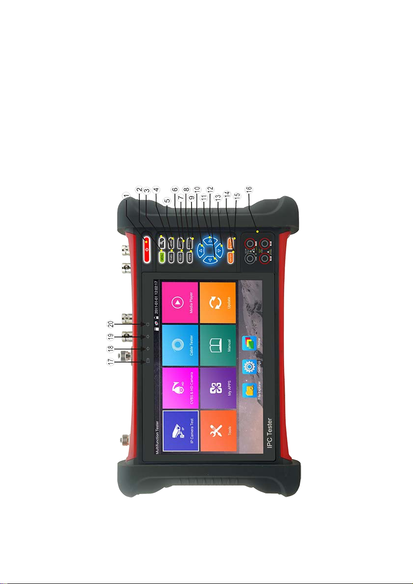
2.3 Function interface
Page.3.
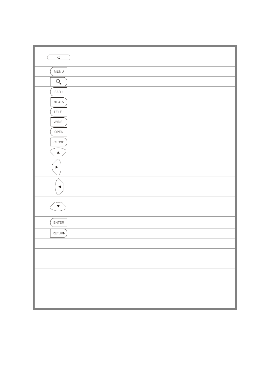
Press 2 seconds or more to turn on or off the device. Short press to illuminate the
1
2
3
4
5
6
7
8
9
10
11
menu display
Menu key; press to call shortcut menu
4xzoom image display
Far focus: Focus the image faraway
Near focus: Focus the image nea rby
TELE: zoom in the image
WIDE: zoom out the image
Open/set ,Confirm the setting of parameters, open or enlarge the aperture
Close/Return: Retu rn of cancel; close or decrease apertu re .
Upward, se t function or add parameter. Tilt the PTZ upward
Rightward, select the parameter whose value will be changed. Add the value of the
paramet er. Pan the PTZ right
12
13
14
15
16
17
18
19 The data received indicator: it lights red while the data is being received
20 The power indicator: it lights green while the tester is powered on by the adapter
Leftward, select the parameter whose value will be changed
Downward , set functio n or reduce the value of the parameter. Tilt the PTZ
downward
Confirm key (Long press it to capture screen interface)
Return/Close : Return or close
Multimeter interface (Optional)
The charge indicator: it lights red while the battery is being charged. As t he
charging is complete, the indicator turns off automatically
The RS485 data transmission indicator: it lights red while the data is being
transmitted
Page.4.
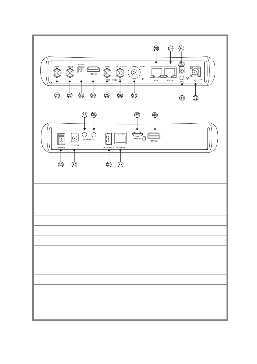
Top interface
Bottom interface
21 TDR cable test interface (Optional)
22 SDI input (BNC interface ) ( Optional)
23 RS485 Interface: RS485 communication for the PTZ
24 HDMI IN
25 Video signal output(BNC interface)/ cable tracer interface
26 CVBS input /AHD /TVI/CVI Coaxial interface (AHD /TVI/CVI Optional )
27 Optical power meter interface (Optional)
28 PoE power supply output or LAN te st port (Use to test PoE or non-PoE IP camera)
29 PSE power sourcing equip ment. Tests PoE voltage
30 DC 12V 2A power output , for provisional DC power supply
31 LED lamp
32
Visible red laser sour ce emits Interface (Optional)
33 Power battery switch
Page.5.

34 DC 12V 2A charging interface
35 Audio input
36 Audio output and earphone interface
37 USB 5V 2A power output (used only for power, not data)
38 UTP cable port: UTP cable tester port/ Cable tracer port
39 Micro SD card moveable ,( comes with 8GB, supports up to 32GB)
40 HDMI output interface
Page.6.
3. Operation
3.1 Installing the Battery
The battery main switch a t th e right-bottom corner of tester bottom。
“0”: Battery power off
“1”: Battery power on
The tester has a built-in lithium-ion polymer rechargeable battery. The tester’s bottom power should be
turned to “0” for safety durin g transportation (the factory default is “0”).
When using the instrume nt, switch pow er button to “1”, press the several seconds to turn
on/off tester. In general, the user does not ne ed to turn on battery switch. When not in use for an
extended pe riod, turn off the switch.
Notice: Use the original adaptor and connected cable of the device!
When the battery icon is full, or the charge indicator turns off automatically, it indicates the
battery charging is completed.
Notice: When the Charge Indi cator turns off, the battery is approximately 90% charged.
The charging time can be extend ed for about 1 hour and the charging time within 12
hours will not damage the battery.
Notice: Press the key several seconds to restore the default settings when the
Instrument works abnormally.
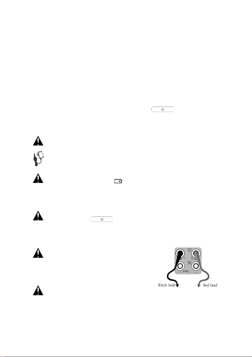
Multi-meter: the red and b lack multi-meter probes must insert the
Warning: Do not insert a 6V source load into the
Instrument communi c ation port, or you could damage
the tester.
Warnings: Do not ins ert multi-meter probes in the
current ter m i na l to measure voltage.
correct corresponding port.
Page.7.
3.2 Instrument connection
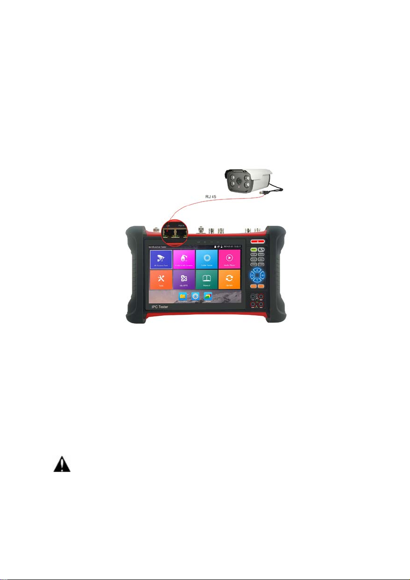
3.2.1 IP camera connection
Power an IP camera with an independent power supply, then connect the IP camera to the IPC tester’s
LAN port, if the link indicator of the tester’s LAN port is green and th e data indicator flickers, it means
the IP camera and the IPC tester are communicating. If the two indicators don’t flicker, check if the IP
camera is powered on or the networ k cable is not functioning proper ly.
Note: 1) When the IP camera requires Po E power, the test can supply power th rough the IP tester’s
LAN port. Turn on or off the PoE power by clicking the icon “POE powe r output” in Normal mode, or
from the IP Camera Test app in Lite mode.
2) A PoE switch or PSE (power sourcing equipment) may be connected to the tester’s PSE port to
supply PoE power to the IP camer a through the tester’s LAN port. A POE switch or PSE can on be used
when the tester’s PoE power is turned off. On this condition, the tester cannot receive data from IP
camera, but the com p uter connec ted to the PoE sw itch can receive the data via the tester.
Warning: PoE switch or PSE (power sourcing equipment) can only be connected to tester “PSE
IN” port; otherwise it will damage the tester.
Page.8.
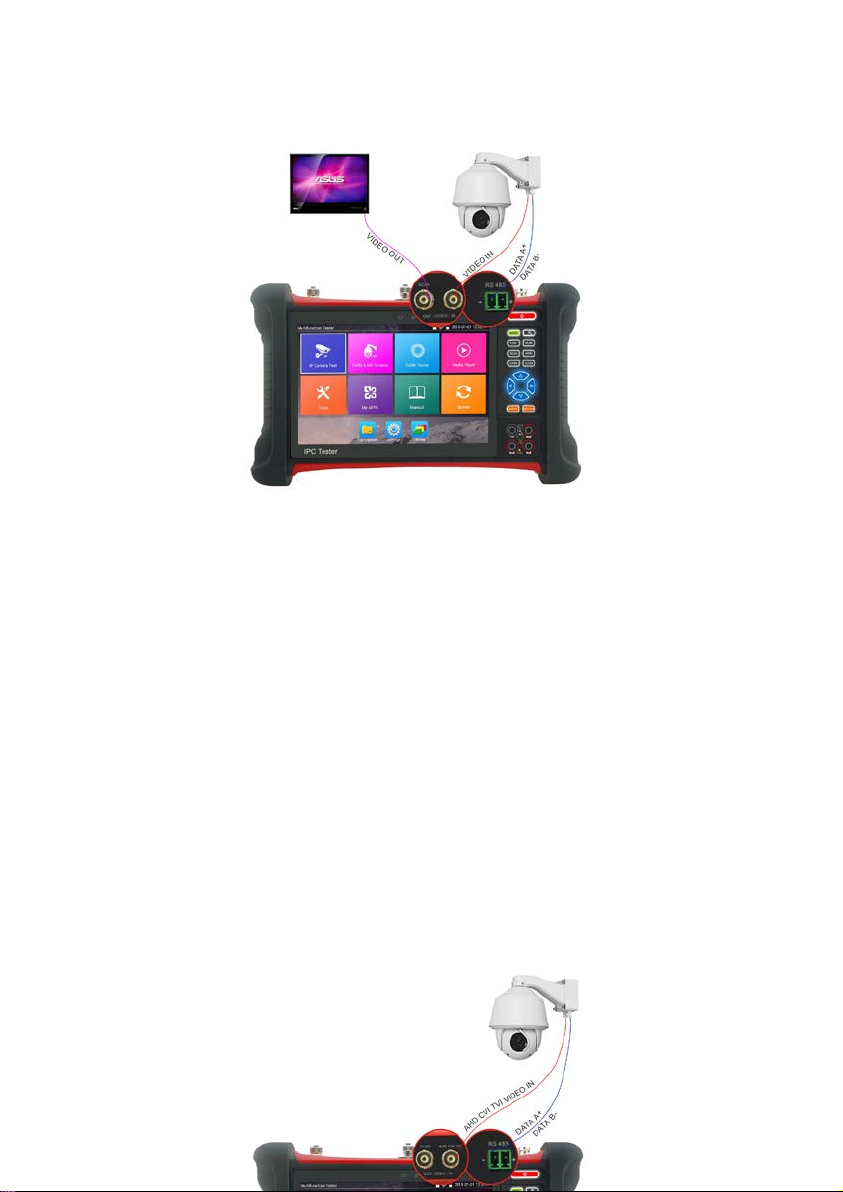
3.2.2 Analog camera connection
(1) ) Connect the camera 's vid eo output to the IP tester’s VIDEO IN. The image will display on the
tester afte r pu s hing the PTZ icon.
(2) CCTV IP Tester “VIDEO OUT” interface connect to the Video input of monitor and optical video
transmitter and receiver, the image display on the tester and monitor.
(3) Connect the camera or th e spe ed dome RS485 controller cable to the tester RS485 interface ,(Note:
positive and negative connection of the cable).
3.2.3 HD Coaxial camera connection
* SDI/EX-SDI, CVI, TVI, AHD camera are classified as HD coaxial c ameras. Hereby the following
instruction of how to connect SDI camera to the tester is also applied to CVI, TVI, and AHD camera.
Page.9.
(1) Connect the SDI camera's video output to the IP tester’s “SDI IN” interface and the image will
display on the tester when choosing the “SDI” icon on the tester.
(2) Connect the SDI camera or th e speed dome RS485 controller cable to th e tester RS485 interface,
(Note: positive and neg ative conn ection of the cable).
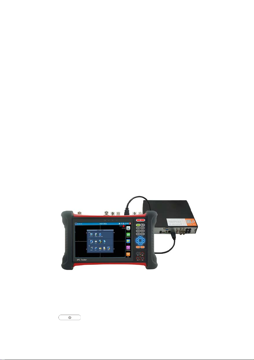
3.2.4 HDMI IN
Attach a DVR or other device’s HDMI out port connect to tester’s HDMI in port and the tester will
display the input image.
3.3 OSD menu
Press the key 2 seconds to turn on
Page.10.
Press the key again to turn off
Short press the key to enter sleep mode, press it again to test.
If tester works abnormally and cannot be turned off, Press the key several seconds to turn
off and the tester will reset.
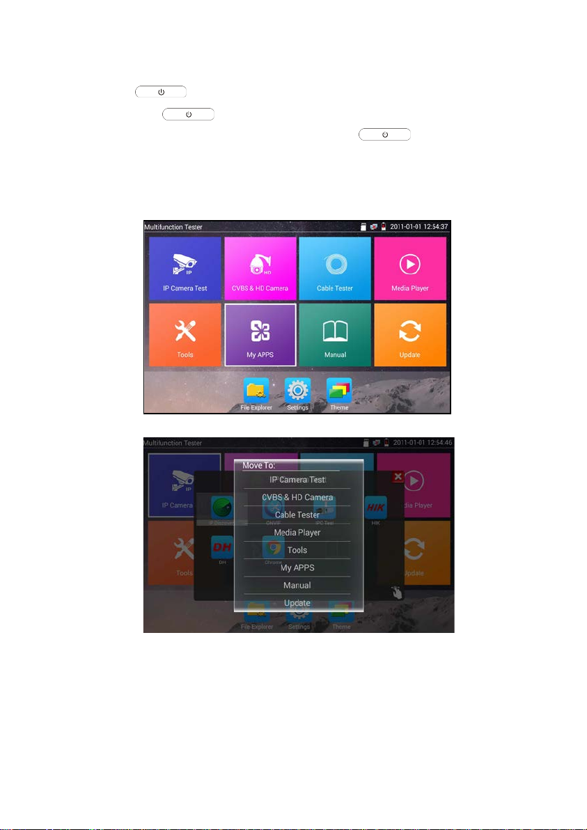
3.3.1 Lite mode & Norma l mo d e
Lite mode: Easily find corresponding apps
In Lite mode, Press the icon several seconds, can move the icon to other apps.
In Lite mode, click the finger icon in the lower right corner to release locked icons, move icons
and chan ge sequence of icons.
Norma l mode
To change to Normal mode, choose the “Theme” tab and then press “Desktop style” to toggle
between Normal mode and Lite mode.
Page.11.
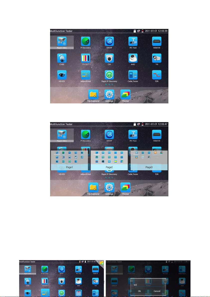
In Normal mode, press icon several seconds so icon can be dragged within a page or moved to other
pages.
This allows the user to in dividualize t he tester to specific req ui r em ents.
Create New Folder: Drag the icon to the folder in top right corner, enter the folder name. Icon will be
auto placed in the new named folder.
Page.12.
Press the folder severa l seconds, to change the folder name, you can move the icon out of folder, the
folder will be auto delet ed until move out all icons.
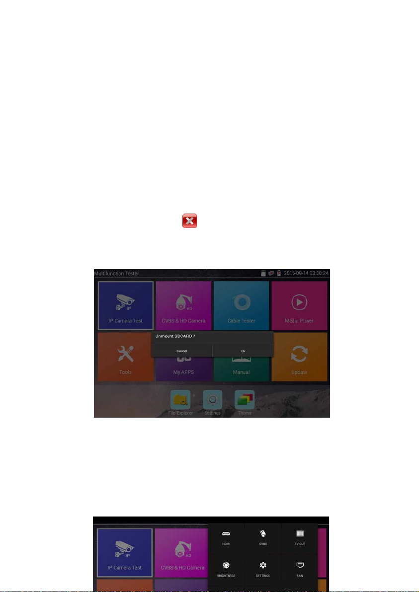
Select Icons to enter, if quit, please click
Click “SD card” from “Settings” menu to install or remove SD card.
3.3.2 Drop-down Menu
Press and slide at top of screen twice to open shortcut menu. The shortcut menu includes POE power
output, IP settings, HDMI IN, CVBS, LAN info, Settings, etc.
Page.13.

HDMI: Click HDMI IN to enter th e HDMI input mode, where th e teste r can displa y a dual test
window (picture in pictu re) with IP & HDMI inputs or Analog & HDMI inputs.
CVBS: C lick icon “CVBS” to ente r CVBS input mode where the test er can display both an IP
and analog camera at the same time.
TV OUT: Click “TV out” to enter floating win dow (picture-in-picture) of the color-bar
generat or to send thr ough the BN C/CVB S outpu t to a video monitor for color bar testing
of monitor and cable.
LAN: Display network port or WIFI connection real-time upload and download speeds and
other network parameters.
Brightness: Set brightness
Settings: Enter settings interface .
IP: Enter IP Settings interface.
POE OUTPUT: Turn on or off the tester’s POE power output to the LAN port.
WLAN: Turn on WLAN net and displays current WLAN sta tus.
3.3.3 Short cut -menu
The shortcut menu can be acc e s sed by pressi ng t he tester’s “me nu” key.
Page.14.
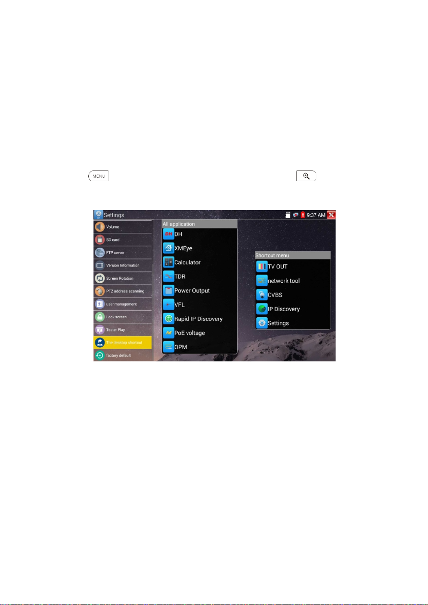
Press the key to turn it on, arrow keys to switch functions, and to enter app; tap
outside the menu to exit.
The shortcut menu can be modified from the “Settings” icon. Enter the Short cut setting and long
press any ap p i n the “All applications” list and it will auto move to shortcut menu. To delete any app
in the short cut menu, press the app for several seconds and it will be deleted.
Page.15.
3.3.4 Screen capture
Long press the “enter” ke y to ca pture screen interface and save it at any time.
User can go to “File Explore r” to view documents, pictures, vid eos and screenshots.
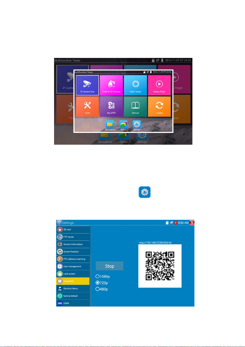
3.3.5 TesterPlay
TesterPlay is a mobile sc reen projection (for android versions only).
The tester creates a WIFI hotspot to co nnect mobile phone to the tester’s WIFI hotspot, or the tester and
mobile pho ne connect to the same WiFi network. Tap icon “ ”, then select “TesterPlay” app to
enter where the meter generates two-dimensional code. Scan the code with mobile phone and download
and install the client software. The tester’s screen can be viewed in real-time pro je ction.
Page.16.
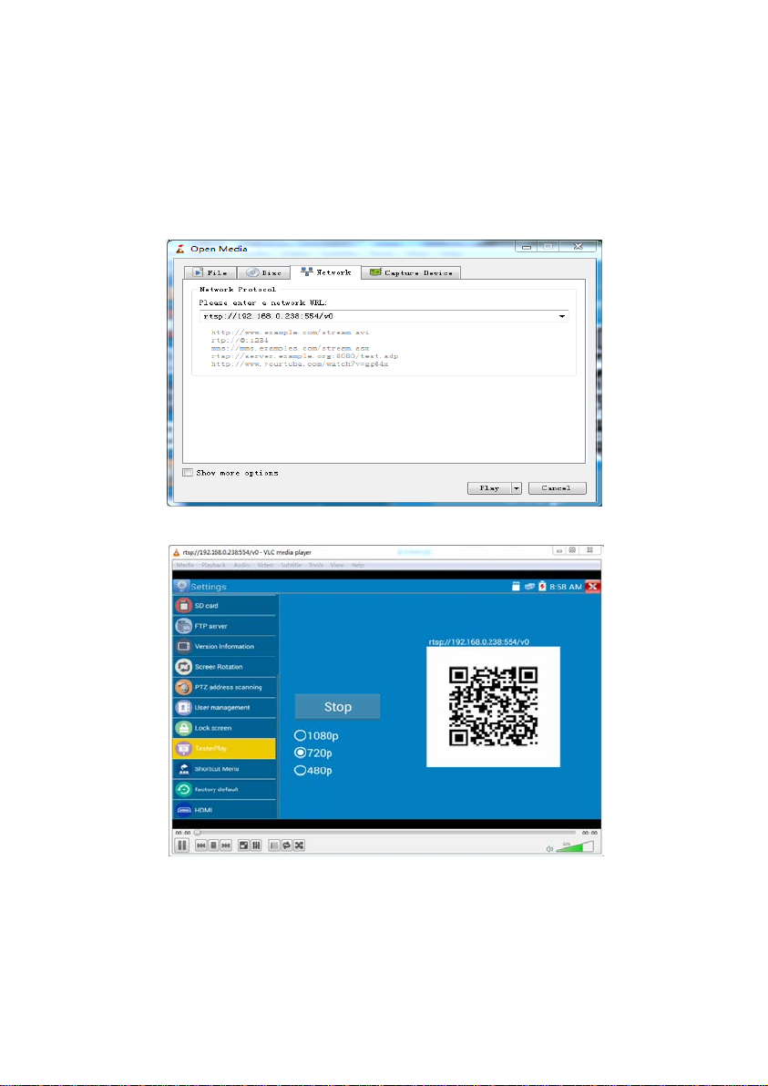
PC screen projection:
Install VLC player in the PC, turn on the VLC player, go to "Media”, “Open Network
Streaming", and input t he R T S P a d dress of on the top instrume n t tw o-dimensional code, click
"play" to view the screen real-time proj ection.
Page.17.

3.3.6
Rapid video
In Normal Mode, press the Rapid video icon, for one key detection of all network cameras
and auto play the images.
Auto log in and display camer a image (for detailed operation refer t o ONVIF function).
Page.18.
:
After entering the ONVIF app, click Refresh to search ip address.
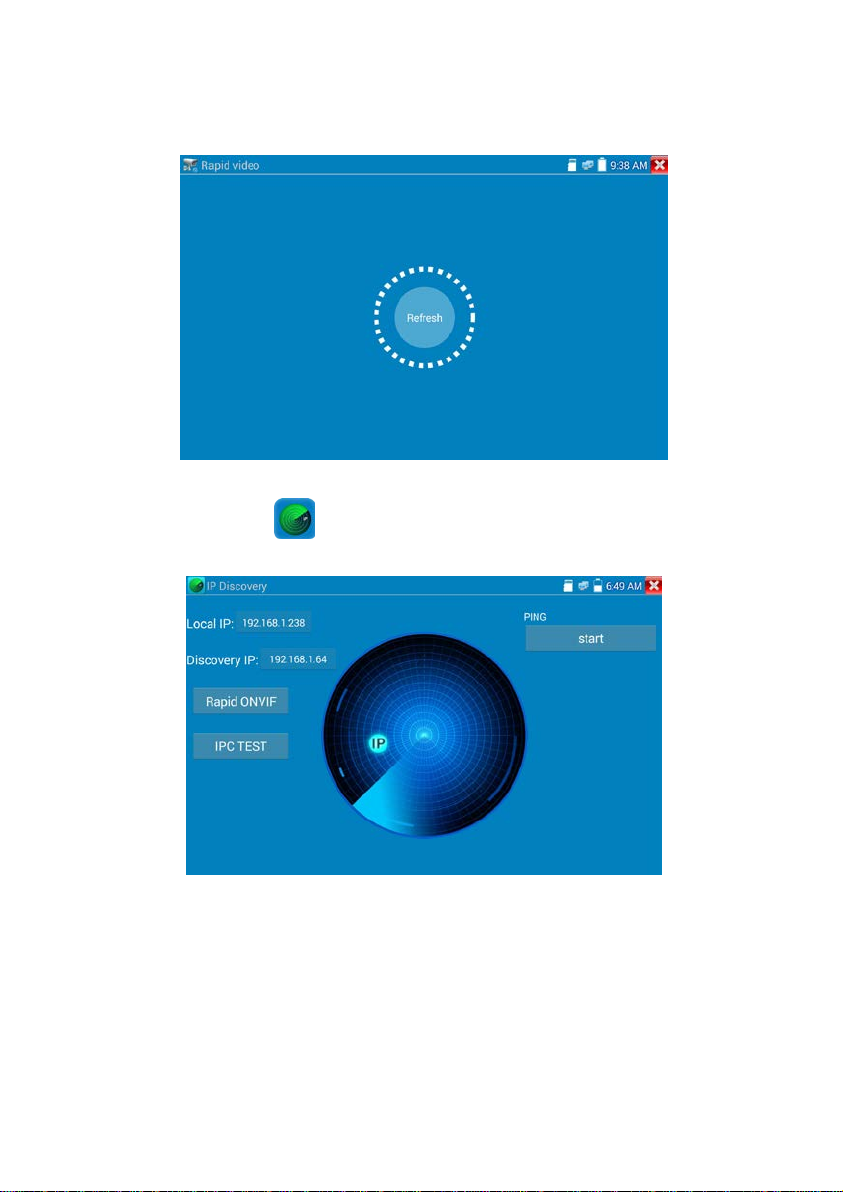
3.3.7 IP discovery
Press IP discovery for tester to auto-scan the whole network segm ent IP, as well as
auto-modify the tester‘s IP to the same network segment with the scanned camera's IP.
Local IP:Tester’s IP address where the teste r can auto-modify the tester‘s IP to the same network
segment with the scanne d c a mera's IP
Discovery IP
connected to the teste r directly, tester will display the camera’s IP address; if tester is conn ected to
Local Area Network, it displays the current IP address.
Discovers connected equipment’s (usually camera) IP address. If the camera is
Page.19.
:
:
Temp IP:after searching IP address, the modified tester’s IP address will not be saved, if you do not
select “Temp IP,” the modified tester’s IP address will auto-save af te r searching.
To start the PING function click "Start" to PING camera’s IP
Start
Rapid ONVIF: Rapid ONVIF Quick link
IPC TEST: IPC TEST Quick link
Applicability
address , it can auto-scan the whole network segment IP, and auto-modify tester’s IP address , greatly
improving engineering efficiency.
Using IP discovery app ,you don’t need to know the first two digits of camera’s IP
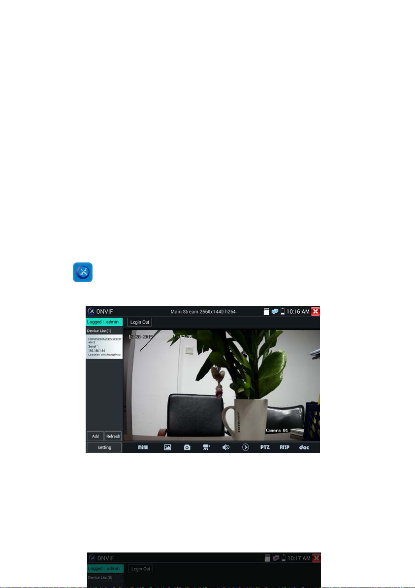
3.3.8 Rapid ONVIF test
Rapid ONVIF can display 4K H.265/H.264 camera image by tester mainstream and one key to activate
Hikvision camera.
Press enter ONVIF function and the tester will auto scan all ONVIF cameras in different
network segments.
Tester can auto login camera and display camera image. Factory default use admin password to auto
login, if you modified the password, then default use the modified password to log in.
If you select ONVIF Rapid mode, the meter automatically scan different network segments for ONVIF
Page.20.

cameras. It lists the camera name and IP address on the Device List. Tester can auto login camera and
display camera image.
Click the button “Refresh”; tester will scan the ONVIF camera again. Click the newly displayed ONVIF
camera on the “Device List“. The tester will show the IP camera’s relative information and settings.
Activate HIKVISION Camera: When connected unactivated HIKVISION Camera, tester can auto
recognized and prompt "The camera is not active, you need to activate it", click "OK" to start
activation.
Page.21.
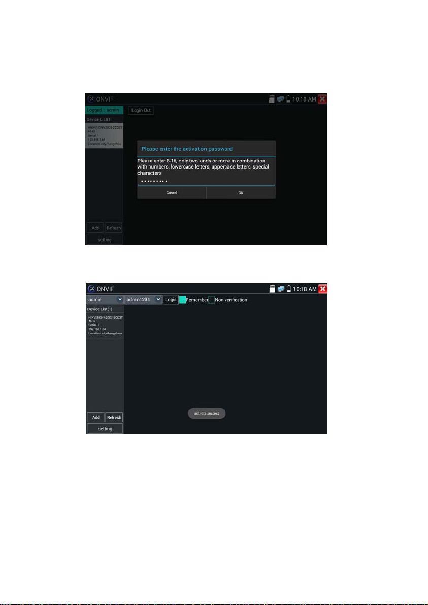
Enter a ne w password for the camera.
When tester d isplays “activate success” prompt, click login to display camera image.
Page.22.
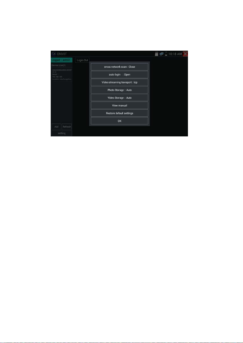
Pop-up settings menu when click the “ONVIF” icon in the upper left corner
Across network segments scan: After open this function, enter “Settings,” “ IP Settings” and
“Advanced” to add other network segments IP so Rapid ONVIF function can cross network segments to
scan camera’s IP.
Auto Login: After open this function, tester can auto login camera and disp lay camera image. (The
login password is the same with last time, the first time using pa ssw o rd is the def a ul t password
"admin")
Video transmission protocol: UTP and TCP protocol.
Open password cracker: Cracks password of cameras.
View manual: Open Manual.
Restore Defaults: Revert “Rapid ONVIF” to default settings.
OK: Save the mo dified para meters.
Click the “MENU” icon, at the bottom of the screen, to open c am era setting s.
Page.23.
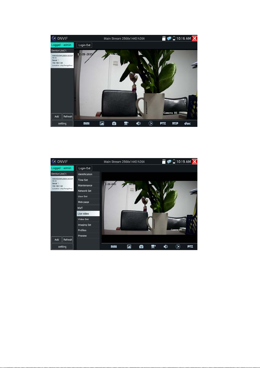
While in the live video, the Video Menu is across the bottom of the screen and provides access to the
following tools: Snapshot, Record, Photo, Playback, PTZ, R TSP and docs.
ONVIF PTZ control: Tap the image in the direction you want the PTZ ca mera to move. For example,
tap the left side of the image t o move left, right to go right, up to go up and down to go down.
Compatible IP PTZ cameras will rotate accordingly. PTZ rotation direction is displayed on top left
corner of the image.
Page.24.
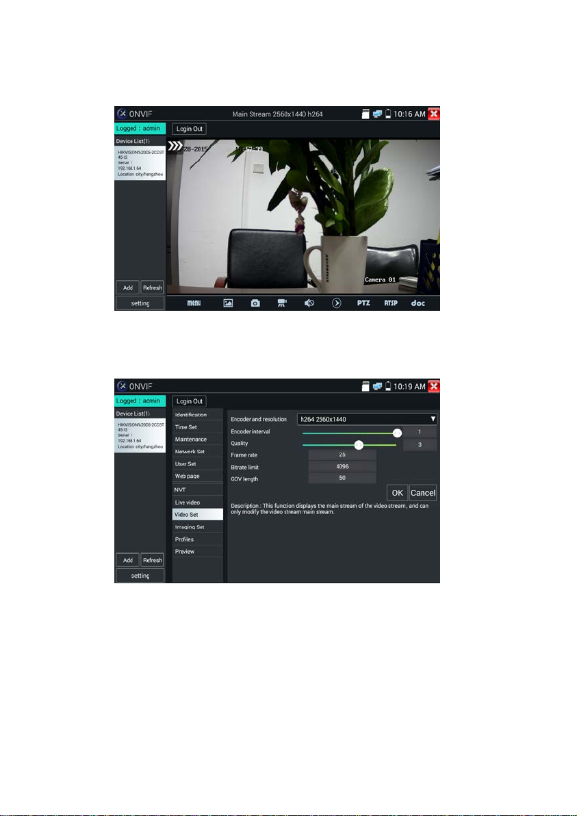
IP camera video settings: Click “Menu” and click “Video Set” to enter the IP camera’s encode r and
resolution settin gs. Make the desired changes and click “OK “to save.
Page.25.
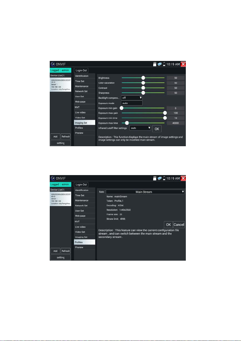
Image setting: Click “Imaging Set” to adjust image brightness, saturation, contrast, sharpness and
backlight compensation mode.
Profiles: Click “Profiles" to view video streaming current configur ation files, a s w e l l as sw i tch between
Major stream and minor str eam.
Page.26.
 Loading...