

Tenma 72-1055 Operating Manual
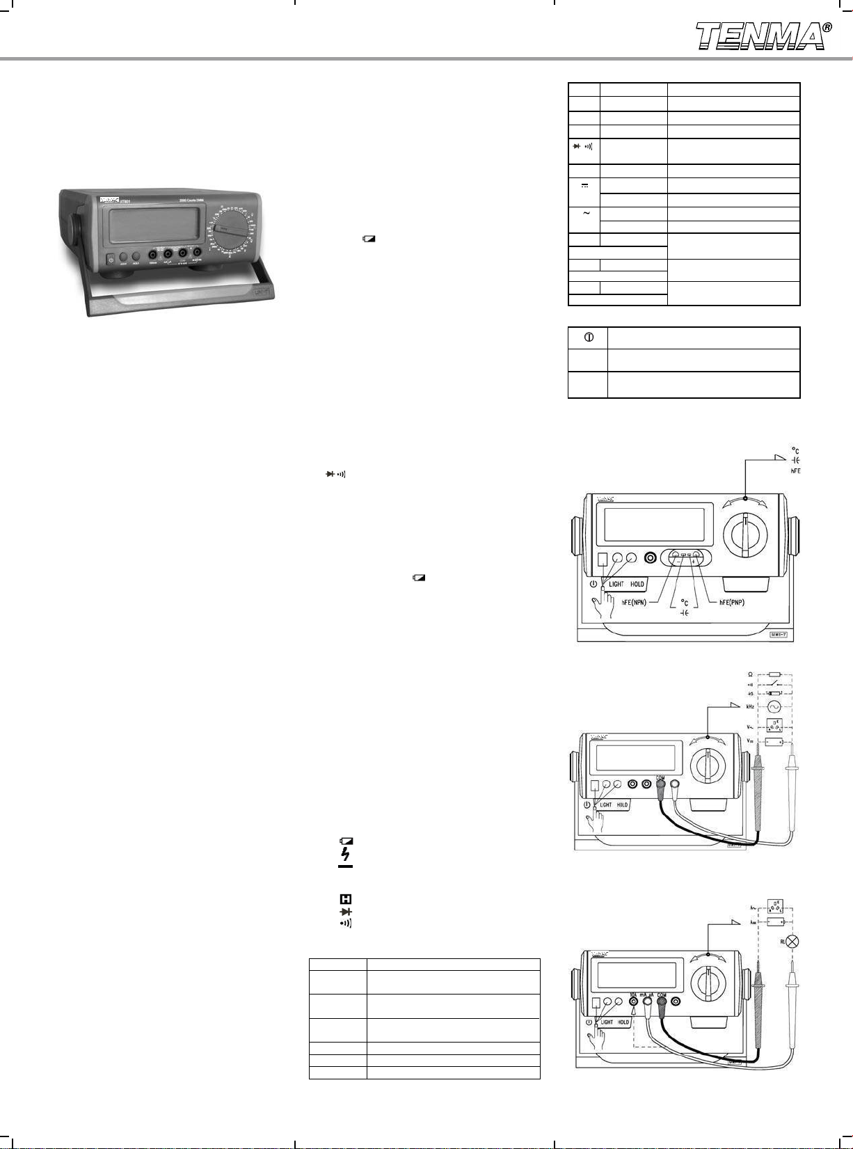
72-1055 Operating Manual
72-1055
Operating Manual
Bench Type Digital Multimeter
Overview
Digital Bench-Type Multimeter Model 72-1055 is
a manual ranging, DC / AC current digital multimeter.
This model features a 2000 count, 3-1/2 digit, extralarge, backlit LCD display.
This easy-to-use instrument provides the user full
measurement and full overload protection, packaged
in a sleek and simple casing that will fit on any bench.
Measurements include DC/AC voltage, DC/AC
current, resistance, frequency, capacitance, temper-
ature, transistor hFE, diode, and continuity
buzzer.
This operating manual covers information on
safety and precautions. Please read all of the
information carefully and observe all the warnings
strictly while using this product.
Unpacking Inspection
Open the box and carefully remove the meter.
Check the following items to see if there are missing
or damaged parts. If you nd any missing or damaged
parts please contact your Tenma dealer.
● Operating Manual 1 piece
● Test Lead 1 pair
● Alligator Clip 1 pair
● K Type Temperature Probe 1 piece
( Maximum 230 Celcius)
● Multi-Purpose Socket
● Power Cord 1 piece
(AC220V 50Hz DC9V/200mA)
Safety Information
T h i s Me t e r co m p l ies with the stand ards
IE C61 01 0 -1 for pol lut io n d egr ee 2, ove r vo l ta ge
category (CAT II 1000V) and double insulation. Please
follow these operating instructions while using the
meter to reduce the chance of damage or possible
injury.
1. Inspect both the Meter and the Test Leads before
use. Do not use the Meter and Test Leads
if either is damaged, if the protective housing is
removed or the display is blank while in use. Do not
use the meter with the housing removed;;;;;;;;;;;. Damage
to the case or insulation could cause electric shock
or cause further damage to the meter and any attached
equipment being tested.
2. If test leads are damaged, use only the same
model num ber or identical electrical specification
replacement parts.
3. Do not touch any cable, connector, terminal or
other circuit being tested with your bare skin or hands.
4. When the meter is being used with voltages over
60V DC or 30V rms AC RMS, additional care should
be taken for added danger of electric shock.
5. Select the correct terminal input and turn the
rotary switch to sele ct the meas uring fu nction. If you
are not sure of the current range, simply start with a high
value and adjust down until you get a a reading.
1 piece
6. Do not overload voltage or current between the
terminals or between the terminals and a ground;;;;;;,
which the meter will indicate the overload.
7. Once the rotary switch is placed in the correct
range position, do not change the range during the
measurement function.
8. Do not use or store the meter in a high temperat u re , high hum idi t y, f lam mab l e, or highly
electromagnetic environment. The performance of
the meter may deteriorate after this type of use.
9. Do not alter the interna l circuit of the meter
for any reason. Doing so will cause damage to the
meter, and possibly cause injury or death.
10. Replace the ba ttery a s soon as the batt ery
indicator “ ”appears. With a low battery, the
meter might produce false readings that can lead to
electric shock and even personal injury.
11. Turn the meter off when it is not is use. Take out
the batteries when not used for extended period of time.
General Specications
1. Maximum Voltag e betwe en termi nal inpu t and
COM: 1000V (except 200mV, 230V)
2. μA mA terminal input protection: (CE)250mA 265V
auto recovery fuse
3. 10A terminal input prot ec tion: ( CE)F1 ( 10A H
250V) Fast blow fuse Φ5x20mm
4. Resistance input protection: PTC/250V
5. Capacitance input protection: (CE)F2, F3 (0.5A H
250V) Fast blow fuse Φ5x20mm
6. Frequency input protection: PTC/250V
7. Temperature input protection: (CE)250mA 265V
fuse
8. terminal input protection: PTC/250V
9. hFE input pr otection : (C E)250mA 265V auto
recovery fuse, F3 (0.5A H 250V) Fast blow
fuse Φ5x20mm
10 . Disp l a y : L C D f u l l f u nct i o n sig n a l d i spla y,
maximum reading is 1999, and updates 2-3 times /sec
11. Range: Manual
12. Polarity Display: Auto
13. Overload indication: 1
14. Battery Deciency:
15. Operating Temperature: 0~40℃(32℉~104℉)
16. Storing Temperature: -10~50℃(14℉~122℉)
17. Relative Humidity: 0℃~30℃ below ≤75%
30℃~40℃ ≤50%
18. Electromagnetic Field: Under 1V/m from inuence
of radia ted radi o-freque ncy elec tromagne tic fiel d
effect, Total accuracy= specific accuracy+
measurement 5%, Over 1V/m radiated radiofrequency electromagnetic whic h do not have any
reference data on this topic.
19. Power: AC (external power adapter AC110V/
DC9V-200mA) or DC (internal battery type 2 R14/1.5V
6 pieces)
20. Product size: 300 x 245 x 105 mm
21. Product Net Weight : About 3.3 lbs (without
accessories)
22. Safety Compaliances : IEC 61010: CATⅡ1000V
LCD Display
1. Manual Range
2. Warning
3.
4.
5.
6. AC Indicator for AC voltage or current
Manual Range Indicator
Warning Indicator
!
Low Battery
High voltage
Negative Reading
( DC indicator do not display)
7.
8.
9.
10. Number Test reading
11. Units of measurement:
μA, mA, A
Ω, kΩ, MΩ
Data Hold
Diode Test
Continuity Alarm
mV, V
nF/μF
Unit of Voltage: millivolt, volt
Unit of current: Microampere, milliampere,
ampere
Unit of electrical resistance: Ohm, thousand
ohms, trillion ohms
Unit of electrical capacity: Accepts farad,
microfarad
Unit of Frequency: Kilohertz
kHz
Unit of Temperature: Degree Celsius Factor
℃
Unit of Triode enlargement: Times
β
Functions
Symbol Terminal Input
V V
←→
Explanation
COM DC Voltage Measurement
V V ←→ COM AC Voltage Measurement
←→
Ω V
V
COM Resistance Measurement
←→
COM Diode / Continuity Buzzer
Measurement
←→
kHz V
A
10A
A
10A
F V←→ mA μA
(Use Multi-Purpose Socket)
℃
V
(Use Multi-Purpose Socket)
hFE V ←→mA μA Triode Enlargement Factor
(Use Multi-Purpose Socket)
COM Frequency Measurement
mA μA ←→ COM
←→
mA μA ←→ COM
←→
←→
mA μA
mA/μA DC Current Measurement
ADC Current Measurement
COM
mA/μA AC Current Measurement
A AC Current Measurement
COM
Capacitance Measurement
Temperature Measurement
Measurement
Functional Buttons
Power Toggle Button
Display backlight power
LIGHT
Press Hold to enter and exit the hold mode
HOLD
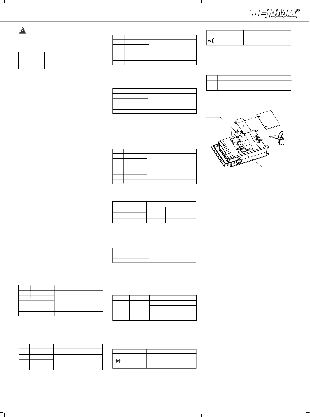
Operational Measurement Guide (see Diagram 1, 2,
3)
Diagram 1
Diagram 2
Diagram 3
Warning:
1. Select the correct terminal input and turn the
rotary switch to select the measurement function. If
this is not done correctly, an alarm will sound and a
warning signal will be displayed.
Range Alarm Alert On False Terminal Input
V Hz Ω 10A mAμA
mAμA ℃ hFE F 10A
10A mAμA
2.DC or AC Voltage Measurement
●
To avoid personal injury or damage to the meter
from electric shock, please do not attempt to measure
voltages higher than 1000 V (although reading may
be obtained).
● Th e Me t e r h a s a n i n p ut i m p e da n ce o f
This loading effect can cause measurement
10MΩ.
errors in high impedance circuits.
3.DC or AC Current Measurement
● Before connecting the Meter in line with a return
circuit, disconnect
danger of sparking.
the circuit current to avoid any
● Do not use over a 10A current measurement.
The meter will measure up to a 20A current, but any
current over 10A could cause personal injury and
damages to the Meter.
4. Me asu ri ng Resis ta nce , Dio des , Con ti nui ty or
Capacitance
● To maintain measurement accuracy, disconnect
cir cu it po we r and disc harge any high volta ge
capacitors when measuring resistance.
● When meas uring hi gh re sista nce on 1MΩ or
ab ov e, it is norm al to tak e sev era l sec on ds to
obtain a stable reading. In order to obta in stable
readin gs, choose shorter test leads for this type of
measurement.
● The te st leads and the internal meter wiring will
add about 0.1Ω 0.2Ω of error to resistanc e
~
measurement when measuring low resistance. To
obtain accurate readings in low-r esi sta nce, short
–circui t the test leads before testing an d recor d the
reading obtained. Subtract this value from the actual
measured resistance value of your test to come up with
accurate resistance readings.
● During measurement, Diodes with a good silicon
junction typically drop to 500mV 800m V.
When measuring continuity, the buzzer will sound
●
if the measured resistance is greater than 10
~
Ω. The
display will read the approximate resistance value.
Accuracy Specications
Accuracy: ±(% reading + digits), guaranteed for 1 year
Operating temperature: 18℃~28
℃
Environmental humidity: Less than 75%RH
1. DC Voltage
Range Resolution
200mV 0.1mV
2V 1mV
20V 10mV ±(0.5%+2)
200V 100mV
1000V 1V ±(0.8%+3)
Accuracy Tolerance:±(% Reading+Digits)
Input impedance is on aver ag e 10MΩ
Maxim um Voltage I nput: 1000V (Except 200mV,
250V)
2. AC Voltage
Range Resolution
2V
1mV
20V
10mV
200V
1000V
Input impedance is on aver ag e 10MΩ
Maximum Voltage Input: 750Vrms
100mV
1V
Accuracy Tolerance:±(% Reading+Digits)
±(0.8%+3)
±(1.0%+4)
Frequency: 45Hz~400Hz
Display: True RMS
3. DC Current
Range Resolution
200μA 0.1μA
2mA 1μA
20mA 10μA
200mA 0.1mA
10A 10mA
Accuracy Tolerance:±(% Reading+Digits)
±(0.8%+2)
±(2.0%+4)
* When ≥5A, Continuous measurement less than 10
seconds at an interval more than 15 minutes.
4. AC Current
Range Resolution
2mA
1μA
20mA
10μA
200mA
0.1mA
10A
10mA
Accuracy Tolerance:±(% Reading+Digits)
±(1.0%+3)
±(2.5%+5)
Frequency: 45Hz~400Hz
* When ≥5A, Continuous measurement less than 10
seconds at an interval more than 15 minutes.
5. Resistance
Range Resolution
200Ω
0.1Ω
2kΩ
1Ω
20kΩ
10Ω
200kΩ
100Ω
2MΩ
1kΩ
20MΩ 10kΩ ±(1.2%+5)
Accuracy Tolerance:±(% Reading+Digits)
±(0.8%+3)
6. Capacitance
Range Resolution
20nF 10pF
2μF 1nF
200μF* 100nF
Accuracy Tolerance:±(% Reading+Digits)
±(4%+3)
±(5%+5)
*>40 μF c ap ac it an ce meas ur ement as reference
purpose.
7. Frequency
Range Resolution
2kHz 1Hz
200kHz 100Hz
Accuracy Tolerance:±(% Reading+Digits)
±(1.5%+5)
Input Amplitude:
(2kHz range) 50mV≤a≤30Vrms
(200kHz range)150mV≤a≤30Vrms
8. Temperature
Range Resolution
-40 -20 -(8%+5)
~ ℃
>-20 0 ±(1.2%+4)
℃ ℃
>0 100 ±(1.2%+3)
~ ℃
>100~1000
℃
±(2.5%+2)
Accuracy Tolerance:±(% Reading+Digits)
℃
1
* Ther m o cou p l e: It is sui t a ble to use K -ty pe
therm oc ou pl e. The incl ud ed poin t cont ac t K -ty pe
thermocouple can only be used on less than 230
℃
temperature measurement.
9. Diode Test
Range Resolution Remarks
1mV
Ope n circui t voltag e is appx 3V,
Silic on junc tion drops between
0.5
0.8V as the normal value.
~
10. Continuity Test
Range Resolution Remarks
1Ω*
O p e n c i r c u i t v o l t a g e i s
approximately 3V
Whe n the circu it is disconn ected wi th a resis tance
value >100Ω, buzzer does not beep.
When the circuit has a good connection with a
resistance value ≤10Ω, the buzzer beeps continuously.
11. Transistor hFE
Range Resolution Remarks
1β*
hFE
Ib 0 i s ab out 10μ A, Vc e i s
about 2.5V
Replacing the battery(see Diagram 4)
C Cell (R14) 1.5V x6
Power
adapter
Fuse
Diagram 4
Specifications and oth er information shown on this
ins tr uction manu al ar e subject t o change with ou t
notice
Made in China for Tenma
 Loading...