

Telefunken TSAL4400 Datasheet
TSAL4400
Vishay Telefunken
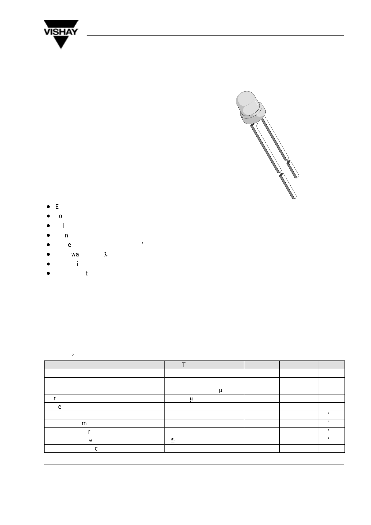
GaAs/GaAlAs IR Emitting Diode in ø 3 mm (T–1)
Package
Description
TSAL4400 is a high efficiency infrared emitting diode
in GaAlAs on GaAs technology , molded in clear , bluegrey tinted plastic packages.
In comparison with the standard GaAs on GaAs
technology these emitters achieve about 100 % radiant power improvement at a similar wavelength.
The forward voltages at low current and at high pulse
current roughly correspond to the low values of the
standard technology. Therefore these emitters are
ideally suitable as high performance replacements of
standard emitters.
Features
D
Extra high radiant power
D
Low forward voltage
D
Suitable for high pulse current operation
D
Standard T–1 (ø 3 mm) package
D
Angle of half intensity ϕ = ± 25
D
Peak wavelength
D
High reliability
D
Good spectral matching to Si photodetectors
lp = 940 nm
°
94 8488
Applications
Infrared remote control units
Free air transmission systems
Infrared source for optical counters and card readers
Absolute Maximum Ratings
T
= 25_C
amb
Parameter Test Conditions Symbol Value Unit
Reverse Voltage V
Forward Current I
Peak Forward Current tp/T = 0.5, tp = 100 ms I
Surge Forward Current tp = 100 ms I
Power Dissipation P
Junction Temperature T
Operating Temperature Range T
Storage Temperature Range T
Soldering Temperature
Thermal Resistance Junction/Ambient R
Document Number 81006
Rev. 3, 20-May-99
t x 5sec, 2 mm from case
www.vishay.de • FaxBack +1-408-970-5600
R
F
FM
FSM
V
amb
stg
T
sd
thJA
5 V
100 mA
200 mA
1.5 A
210 mW
j
100
–55...+100
–55...+100
260
350 K/W
°
°
°
°
C
C
C
C
1 (5)
TSAL4400
g
y
Vishay Telefunken
Basic Characteristics
T
= 25_C
amb
Parameter Test Conditions Symbol Min Typ Max Unit
Forward Voltage IF = 100 mA, tp = 20 ms V
IF = 1 A, tp = 100 ms V
Temp. Coefficient of V
F
IF = 100mA TK
Reverse Current VR = 5 V I
Junction Capacitance VR = 0 V, f = 1 MHz, E = 0 C
Radiant Intensity IF = 100 mA, tp = 20 ms I
IF = 1.0 A, tp = 100 ms I
Radiant Power IF = 100 mA, tp = 20 ms
Temp. Coefficient of
f
e
IF = 20 mA TK
F
F
VF
R
j
e
e
f
e
16 30 mW/sr
135 240 mW/sr
f
e
Angle of Half Intensity ϕ ±25 deg
Peak Wavelength IF = 100 mA
Spectral Bandwidth IF = 100 mA
Temp. Coefficient of
l
p
IF = 100 mA TK
Rise Time IF = 100 mA t
Fall Time IF = 100 mA t
Virtual Source Diameter method: 63% encircled
l
p
Dl
l
p
r
f
ø 2.8 mm
energy
1.35 1.6 V
2.6 3 V
–1.3 mV/K
10
m
25 pF
35 mW
–0.6 %/K
940 nm
50 nm
0.2 nm/K
800 ns
800 ns
A
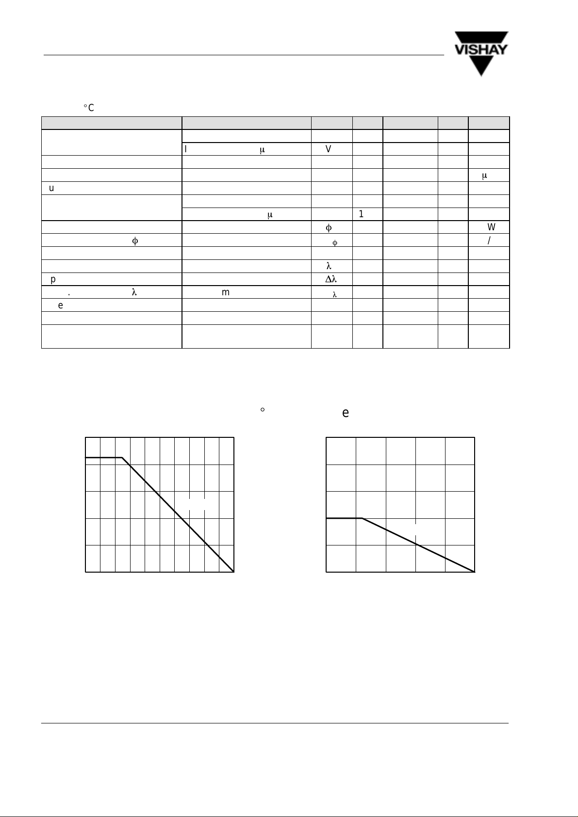
Typical Characteristics (T
250
200
150
R
thJA
100
V
50
P – Power Dissipation ( mW )
0
020406080
T
94 7957 e
Figure 1. Power Dissipation vs. Ambient Temperature
– Ambient Temperature ( °C )
amb
= 25_C unless otherwise specified)
amb
100
250
200
150
100
R
F
I – Forward Current ( mA )
50
0
020406080
T
96 11986
Figure 2. Forward Current vs. Ambient Temperature
– Ambient Temperature ( °C )
amb
thJA
100
www.vishay.de • FaxBack +1-408-970-5600
2 (5) Rev. 3, 20-May-99
Document Number 81006
 Loading...