

Page 1
TED 60-T
PORTABLE OXYGEN ANALYZER
PERAPERA
O
PERA
PERAPERA
TYPE B EQUIPMENT: Equipment providing a particular degree of protec-
TORTOR
TOR'
TORTOR
tion against electric shock, particularly regarding—
SS
S M
SS
• allowable LEAKAGE CURRENT
• Reliability of the protective earth connection
(if present).
ANUALANUAL
ANUAL
ANUALANUAL
Teledyne Analytical Instruments
P/N M40575
12/08/99
ECO # 99-0480
i
Page 2

Copyright © 1999 Teledyne Electronic Technologies, Sensor TechnologiesCopyright © 1999 Teledyne Electronic Technologies, Sensor Technologies
Copyright © 1999 Teledyne Electronic Technologies, Sensor Technologies
Copyright © 1999 Teledyne Electronic Technologies, Sensor TechnologiesCopyright © 1999 Teledyne Electronic Technologies, Sensor Technologies
All Rights ReservedAll Rights Reserved
All Rights Reserved
All Rights ReservedAll Rights Reserved
No part of this manual may be reproduced, transmitted, transcribed, stored in a retrieval
system, or translated into any other language or computer language in whole or in part,
in any form or by any means, whether it be electronic, mechanical, optical, manual, or
otherwise, without prior written consent of Teledyne Electronic Technologies, Sensor
Technologies, 16830 Chestnut Street, City of Industry, CA 91749–1580.
ii
Teledyne Analytical Instruments
Page 3

How To Use This ManualHow To Use This Manual
How To Use This Manual
How To Use This ManualHow To Use This Manual
This manual is designed to walk you through the initial set-up of the TED 60T. After
you have used it to initially install your analyzer, it becomes a quick reference guide to
help you with specific questions or operating problems.
Before you even turn on the instrument, you are advised to read Chapters 1 and 2.
These chapters help you to become better acquainted with the monitor and how it
works before you actually begin to use it.
Please read
manual.
Chapter 2: OperationsChapter 2: Operations
Chapter 2: Operations in its entirety before proceeding further with the
Chapter 2: OperationsChapter 2: Operations
Teledyne Analytical Instruments
iii
Page 4

WarrantyWarranty
Warranty
WarrantyWarranty
Teledyne warrants that the goods are free from defects of material and of constuction
for a period of 2 years from the date of shipment from Teledyne. The Class T-7 MicroFuel Cell is warranted for one year from the date of shipment from Teledyne. The
liability of Teledyne, if any, shall be limited solely to the replacement and repair of the
goods and shall not include shipping costs or other incidental damages as defined in
Section 2-715 of the U.S. Uniform Commercial Code.
This warranty is null and void if any goods are subjected to misuse, negligence, accident, or repairs other than those performed by Teledyne or an authorized service
center.
Caution:Caution:
Caution:
Caution:Caution:
Federal law restricts this device to sale by or on the order of aFederal law restricts this device to sale by or on the order of a
Federal law restricts this device to sale by or on the order of a
Federal law restricts this device to sale by or on the order of aFederal law restricts this device to sale by or on the order of a
physician.physician.
physician.
physician.physician.
iv
Teledyne Analytical Instruments
Page 5

TT
abab
le of Contentsle of Contents
T
ab
le of Contents
TT
abab
le of Contentsle of Contents
11
1
11
22
2 Operations
22
33
3 Maintenance and Troubleshooting
33
Introduction
General Information...................................................................................... 1-1
Applications .................................................................................................. 1-2
Setup .......................................................................................................... 2-1
Battery Installation............................................................................ 2-1
Sensor Installation or Replacement .................................................. 2-2
Calibration......................................................................................... 2-3
Use .......................................................................................................... 2-3
Sterilization ....................................................................................... 2-4
Anesthetic Gases ............................................................................... 2-4
Pressure............................................................................................. 2-5
Humidity............................................................................................ 2-6
Temperature...................................................................................... 2-6
Discrepancy in Readings ................................................................... 2-7
Do's & Don'ts................................................................................................ 2-8
Troubleshooting Table .................................................................................. 3-1
44
4 Appendix
44
Specifications ................................................................................................ 4-1
Spare Parts List............................................................................................. 4-2
Optional Accessories..................................................................................... 4-2
Repair Service............................................................................................... 4-2
Material Safety Data Sheet ........................................................................... 4-3
Teledyne Analytical Instruments
v
Page 6

vi
Teledyne Analytical Instruments
Page 7
Introduction 1Introduction 1
Introduction 1
Introduction 1Introduction 1
IntroductionIntroduction
Introduction
IntroductionIntroduction
General InformationGeneral Information
General Information
General InformationGeneral Information
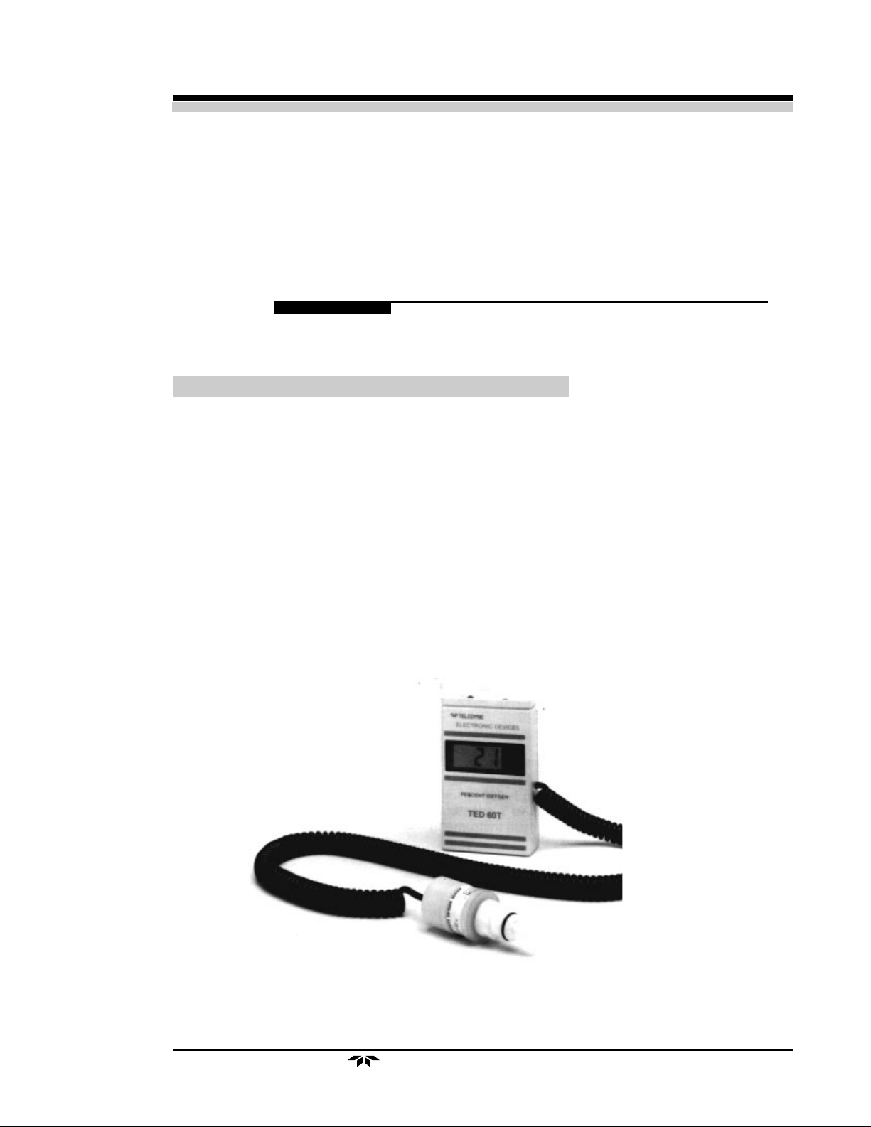
The Teledyne Electronic Technologies 60T Oxygen Analyzer provides analysis in
respirators, incubators, and other medical equipment where specific monitoring of
oxygen is vital. The unit is compact, light, fits comfortably in a pocket, and incorporates
a belt clip for easy carrying. Its 9-volt battery lasts about one year in normal service.
The TED 60T utilizes the Class T–7 Micro-Fuel Cell specifically designed for
medical applications. The sensor is a self-contained galvanic cell with a 90% response
time of typically 6–8 seconds at 5 liters/minute and a life expectancy of 10 months in
100% oxygen (continuous). Replacing the sensor is as easy as unclipping the old sensor
and snapping on a replacement. The low-cost sensor also has an excellent shelf life that
makes keeping spares a sensible proposition.
Front view of the TED 60-T
Teledyne Analytical Instruments
1-1
Page 8

1 Introduction1 Introduction
1 Introduction
1 Introduction1 Introduction
The TED 60T incorporates a combination of important features. The liquid crystal
display (LCD) provides an easy-to-read indication of the oxygen content of the gas
being monitored, with a resolution of 1% oxygen. The upper left-hand corner of the
LCD indicates “BAT” when the batteries are low.
Located on the top panel of the monitor are the ON/OFF power switch and the
calibration control button. The battery is located in the back beneath a sliding cover.
The Class T–7 Micro-Fuel Cell is the heart of the TED 60T. The sensor is connected to a coiled cable one foot (0.3 meter) long which extends to about five feet (1.5
meters).
ApplicationsApplications
Applications
ApplicationsApplications
The TED 60T is designed to analyze oxygen concentrations in a variety of medical
gas mixtures. This instrument should
is recommended that the instrument
verify and spot check the concentration of oxygen in gas mixtures prepared using a gas
blender, anesthesia gas machine, or similar apparatus.
The unit may be used for verifying oxygen concentrations in gas mixtures used in:
• Anesthesia
• Respiratory Therapy
• Neonatal Care
• Intensive Care
never be usednever be used
never be used as a
never be usednever be used
only only
only be used as a
only only
primary monitoring device. It
secondary measuring device secondary measuring device
secondary measuring device to
secondary measuring device secondary measuring device
RFI ImmunityRFI Immunity
RFI Immunity
RFI ImmunityRFI Immunity
The Teledyne Model TED 60-T has been tested to the standard required by the European Community for CE marking, EN 60601-1-2.
The sample subjected to testing passed all sections of this testing with the exception of
the following:
From 26MHz to 250MHz, the display was unstable. When interference
was removed, the equipment under test recovered.
From 250MHz to 1000MHz, the display was stable.
1-2
Teledyne Analytical Instruemnts
Page 9

Operations 2Operations 2
Operations 2
Operations 2Operations 2
Operation
CAUTION:CAUTION:
CAUTION:
CAUTION:CAUTION:
NOTE:NOTE:
NOTE:
NOTE:NOTE:
To set up and use your TED 60T:
UPON RECEIPT, INSPECT THE ENTIRE UNIT FOR DAMAGE. CHECK UNITUPON RECEIPT, INSPECT THE ENTIRE UNIT FOR DAMAGE. CHECK UNIT
UPON RECEIPT, INSPECT THE ENTIRE UNIT FOR DAMAGE. CHECK UNIT
UPON RECEIPT, INSPECT THE ENTIRE UNIT FOR DAMAGE. CHECK UNITUPON RECEIPT, INSPECT THE ENTIRE UNIT FOR DAMAGE. CHECK UNIT
AND INCLUDED ACCESSORIES FOR BROKEN OR LOOSE PARTS. IF DAM-AND INCLUDED ACCESSORIES FOR BROKEN OR LOOSE PARTS. IF DAM-
AND INCLUDED ACCESSORIES FOR BROKEN OR LOOSE PARTS. IF DAM-
AND INCLUDED ACCESSORIES FOR BROKEN OR LOOSE PARTS. IF DAM-AND INCLUDED ACCESSORIES FOR BROKEN OR LOOSE PARTS. IF DAMAGED, DO NOT USE; NOTIFY THE SHIPPER; AND CONSULT TBE SENSORAGED, DO NOT USE; NOTIFY THE SHIPPER; AND CONSULT TBE SENSOR
AGED, DO NOT USE; NOTIFY THE SHIPPER; AND CONSULT TBE SENSOR
AGED, DO NOT USE; NOTIFY THE SHIPPER; AND CONSULT TBE SENSORAGED, DO NOT USE; NOTIFY THE SHIPPER; AND CONSULT TBE SENSOR
TECHNOLOGIES.TECHNOLOGIES.
TECHNOLOGIES.
TECHNOLOGIES.TECHNOLOGIES.
This equipment is internally powered.This equipment is internally powered.
This equipment is internally powered.
This equipment is internally powered.This equipment is internally powered.
Setup
11
1 Install the battery.
11
22
2 Install the sensor.
22
33
3 Calibrate the unit.
33
Battery Installation or ReplacementBattery Installation or Replacement
Battery Installation or Replacement
Battery Installation or ReplacementBattery Installation or Replacement
ss
s
ss
NOTE:NOTE:
NOTE:
NOTE:NOTE:
NOTE:NOTE:
NOTE:
NOTE:NOTE:
A 9-volt alkaline battery must be installed in the unit before the TED 60T canA 9-volt alkaline battery must be installed in the unit before the TED 60T can
A 9-volt alkaline battery must be installed in the unit before the TED 60T can
A 9-volt alkaline battery must be installed in the unit before the TED 60T canA 9-volt alkaline battery must be installed in the unit before the TED 60T can
operate.operate.
operate.
operate.operate.
When new batteries are installed, typically, the unit is suitable for use immedi-When new batteries are installed, typically, the unit is suitable for use immedi-
When new batteries are installed, typically, the unit is suitable for use immedi-
When new batteries are installed, typically, the unit is suitable for use immedi-When new batteries are installed, typically, the unit is suitable for use immediately after installation.ately after installation.
ately after installation.
ately after installation.ately after installation.
1. Turn the unit off (if it is on).
2. Open the battery compartment door. (The battery compartment is below the
belt clip on the rear of the unit. The door slides downward in the direction of
the arrow.)
3. Lift the battery from its compartment and unsnap it from the snap connector.
4. Snap the new battery to the snap conector. (Match up the male and female
snaps. The battery snap connector will only accept a properly oriented
battery. Do not try to force it.
Teledyne Analytical Instruments
2-1
Page 10
2 Operations2 Operations
2 Operations
2 Operations2 Operations
CAUTION:CAUTION:
CAUTION:
CAUTION:CAUTION:
USE ALKALINE BATTERIES ONLY. OTHER TYPES MAY GIVE ERRONEOUSUSE ALKALINE BATTERIES ONLY. OTHER TYPES MAY GIVE ERRONEOUS
USE ALKALINE BATTERIES ONLY. OTHER TYPES MAY GIVE ERRONEOUS
USE ALKALINE BATTERIES ONLY. OTHER TYPES MAY GIVE ERRONEOUSUSE ALKALINE BATTERIES ONLY. OTHER TYPES MAY GIVE ERRONEOUS
READINGS.READINGS.
READINGS.
READINGS.READINGS.
If “BAT” appears in the upper left-hand corner of the LCD, the battery needs
replacing.
Sensor Installation or ReplacementSensor Installation or Replacement
Sensor Installation or Replacement
Sensor Installation or ReplacementSensor Installation or Replacement
NOTE:NOTE:
NOTE:
NOTE:NOTE:
NOTE:NOTE:
NOTE:
NOTE:NOTE:
CAUTION:CAUTION:
CAUTION:
CAUTION:CAUTION:
The T-7 oxygen sensor must be installed before the TED 60T will operate.The T-7 oxygen sensor must be installed before the TED 60T will operate.
The T-7 oxygen sensor must be installed before the TED 60T will operate.
The T-7 oxygen sensor must be installed before the TED 60T will operate.The T-7 oxygen sensor must be installed before the TED 60T will operate.
When a new sensor is installed, typically, the unit is suitable for use immediatelyWhen a new sensor is installed, typically, the unit is suitable for use immediately
When a new sensor is installed, typically, the unit is suitable for use immediately
When a new sensor is installed, typically, the unit is suitable for use immediatelyWhen a new sensor is installed, typically, the unit is suitable for use immediately
after installation.after installation.
after installation.
after installation.after installation.
Do not autoclave the sensor. See page 2.4, Sterilization.Do not autoclave the sensor. See page 2.4, Sterilization.
Do not autoclave the sensor. See page 2.4, Sterilization.
Do not autoclave the sensor. See page 2.4, Sterilization.Do not autoclave the sensor. See page 2.4, Sterilization.
1. Remove the new sensor from its protective bag. Inspect the sensor for
damage or electrolyte leakage. If the sensor is damaged, obtain a replacement. Do not use the defective sensor as it may damage the unit.
CAUTION:CAUTION:
CAUTION:
CAUTION:CAUTION:
The T–7 sensor electrolyte is caustic. Do not let it come in contact with skin.The T–7 sensor electrolyte is caustic. Do not let it come in contact with skin.
The T–7 sensor electrolyte is caustic. Do not let it come in contact with skin.
The T–7 sensor electrolyte is caustic. Do not let it come in contact with skin.The T–7 sensor electrolyte is caustic. Do not let it come in contact with skin.
If it does, flush affected area with water. Do not attempt to open or repair theIf it does, flush affected area with water. Do not attempt to open or repair the
If it does, flush affected area with water. Do not attempt to open or repair the
If it does, flush affected area with water. Do not attempt to open or repair theIf it does, flush affected area with water. Do not attempt to open or repair the
sensor. Check the sensor regularly for leaks. Leaking or exhausted sensorssensor. Check the sensor regularly for leaks. Leaking or exhausted sensors
sensor. Check the sensor regularly for leaks. Leaking or exhausted sensors
sensor. Check the sensor regularly for leaks. Leaking or exhausted sensorssensor. Check the sensor regularly for leaks. Leaking or exhausted sensors
should be disposed of in accordance with local regulations. Consult theshould be disposed of in accordance with local regulations. Consult the
should be disposed of in accordance with local regulations. Consult the
should be disposed of in accordance with local regulations. Consult theshould be disposed of in accordance with local regulations. Consult the
Material Safety Data Sheet in the Appendix.Material Safety Data Sheet in the Appendix.
Material Safety Data Sheet in the Appendix.
Material Safety Data Sheet in the Appendix.Material Safety Data Sheet in the Appendix.
NOTE:NOTE:
NOTE:
NOTE:NOTE:
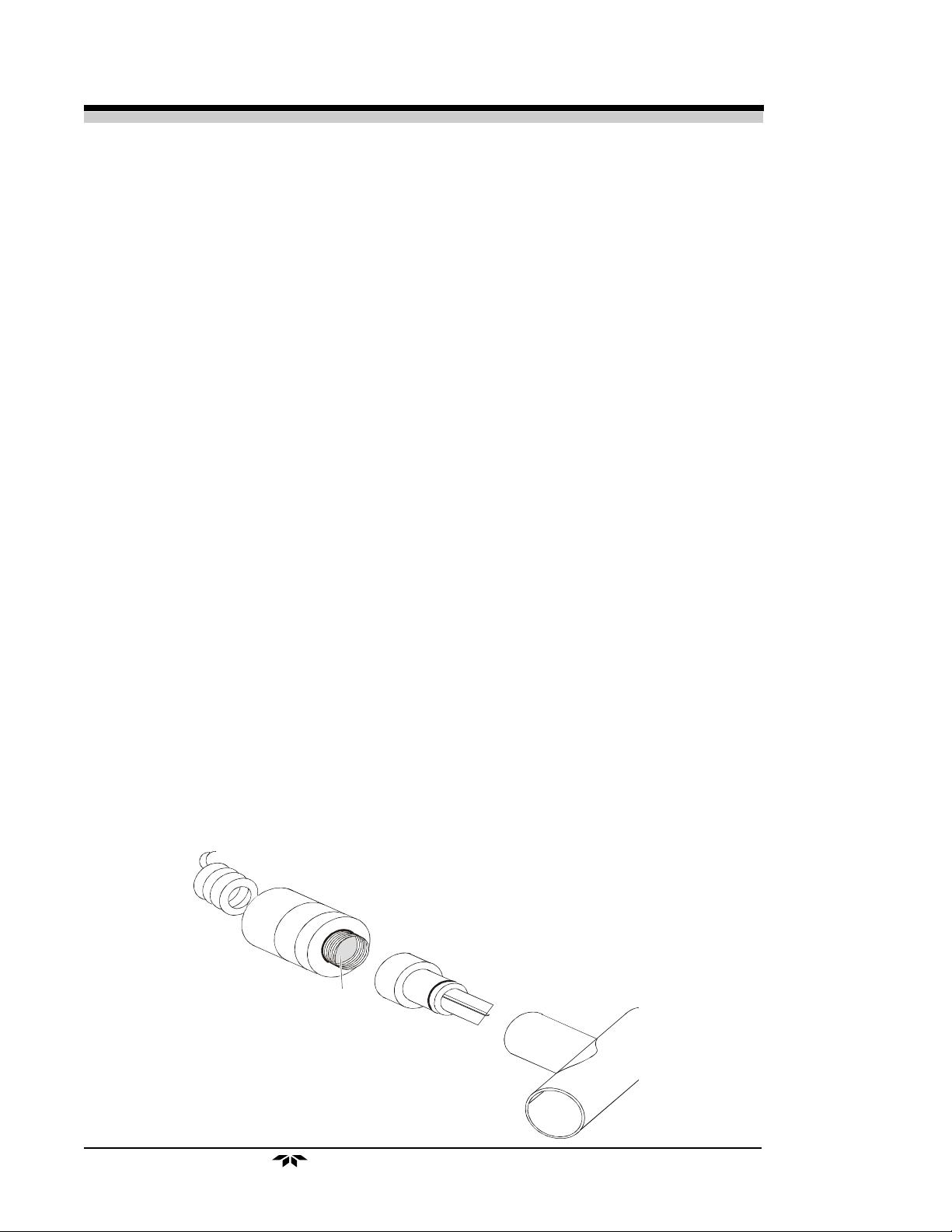
2. Plug the end of the coiled cable into the telephone jack receptacle on the end
of the T-7 sensor, observing proper key orientation. The jack will only fit
one way, so if it does not fit, rotate it until it slides in easily.
If the TED 60T is used for diffusion sampling (i.e., incubators, tents, etc.), theIf the TED 60T is used for diffusion sampling (i.e., incubators, tents, etc.), the
If the TED 60T is used for diffusion sampling (i.e., incubators, tents, etc.), the
If the TED 60T is used for diffusion sampling (i.e., incubators, tents, etc.), theIf the TED 60T is used for diffusion sampling (i.e., incubators, tents, etc.), the
plastic flow diverter must be removed from the T-7 sensor. If the sensor is usedplastic flow diverter must be removed from the T-7 sensor. If the sensor is used
plastic flow diverter must be removed from the T-7 sensor. If the sensor is used
plastic flow diverter must be removed from the T-7 sensor. If the sensor is usedplastic flow diverter must be removed from the T-7 sensor. If the sensor is used
in breathing circuits, etc., the diverter must be used.in breathing circuits, etc., the diverter must be used.
in breathing circuits, etc., the diverter must be used.
in breathing circuits, etc., the diverter must be used.in breathing circuits, etc., the diverter must be used.
Micro-Fuel Cell
Flow
Diverter
Tee
Sensing
Adapter
Surface
2-2
Teledyne Analytical Instruments
Page 11

CalibrationCalibration
Calibration
CalibrationCalibration
Operations 2Operations 2
Operations 2
Operations 2Operations 2
NOTE:NOTE:
NOTE:
NOTE:NOTE:
NOTE:NOTE:
NOTE:
NOTE:NOTE:
Never expose the sensor to varying temperatures (i.e., hold the sensor in yourNever expose the sensor to varying temperatures (i.e., hold the sensor in your
Never expose the sensor to varying temperatures (i.e., hold the sensor in your
Never expose the sensor to varying temperatures (i.e., hold the sensor in yourNever expose the sensor to varying temperatures (i.e., hold the sensor in your
hand) while calibrating.hand) while calibrating.
hand) while calibrating.
hand) while calibrating.hand) while calibrating.
1. Switch the unit ON using “0/I” ON/OFF key.
2. Place the sensor in 100% oxygen.
The flow diverter should only be used with flowing gas circuits.The flow diverter should only be used with flowing gas circuits.
The flow diverter should only be used with flowing gas circuits.
The flow diverter should only be used with flowing gas circuits.The flow diverter should only be used with flowing gas circuits.
3. The CALIBRATE button is located on the top of the unit. Turn the button
by pressing down on it and twisting. Rotate until the display reads 100%.
4. Remove the sensor from 100% oxygen. If the flow diverter is attached,
remove it and expose the sensor to room air. The LCD should display 20–
22%.
5. A calibration check may be conducted at any time to assure proper operation. Remove the diverter and expose the sensor to room air, and verify that
the reading is 20–22%. Expose the sensor to 100% oxygen (preferably using
the diverter and tee adapter in a flow circuit) and verify that the reading is
99–101%.
NOTE:NOTE:
NOTE:
NOTE:NOTE:
NOTE:NOTE:
NOTE:
NOTE:NOTE:
Never calibrate the unit in humidified gas, as water vapor dilutes the calibrationNever calibrate the unit in humidified gas, as water vapor dilutes the calibration
Never calibrate the unit in humidified gas, as water vapor dilutes the calibration
Never calibrate the unit in humidified gas, as water vapor dilutes the calibrationNever calibrate the unit in humidified gas, as water vapor dilutes the calibration
gas and makes the oxygen concentration appear lower than it really is.gas and makes the oxygen concentration appear lower than it really is.
gas and makes the oxygen concentration appear lower than it really is.
gas and makes the oxygen concentration appear lower than it really is.gas and makes the oxygen concentration appear lower than it really is.
UseUse
Use
UseUse
Prior to use, check the calibration and check the sensor for leaks or damage.Prior to use, check the calibration and check the sensor for leaks or damage.
Prior to use, check the calibration and check the sensor for leaks or damage.
Prior to use, check the calibration and check the sensor for leaks or damage.Prior to use, check the calibration and check the sensor for leaks or damage.
The TED 60T can be used to analyze gas mixtures for oxygen in two basic modes:
1.) In breathing circuits or other instances where gases are flowing in tubing
circuits.
2.) In confined volumes such as incubators or tents.
When measuring for oxygen in breathing circuits, the diverter
mustmust
must be used. The
mustmust
diverter should be screwed onto the threaded front end of the T-7 sensor. A tee adapter
Teledyne Analytical Instruments
2-3
Page 12

2 Operations2 Operations
2 Operations
2 Operations2 Operations
(either plastic, P/N A268, or metal, P/N A283) should be placed into the circuit, and the
above sensor assembly plugged into the tee adapter.
CAUTION:CAUTION:
CAUTION:
CAUTION:CAUTION:
Check the breathing circuit for leaks. Be certain that the circuit downstreamCheck the breathing circuit for leaks. Be certain that the circuit downstream
Check the breathing circuit for leaks. Be certain that the circuit downstream
Check the breathing circuit for leaks. Be certain that the circuit downstreamCheck the breathing circuit for leaks. Be certain that the circuit downstream
of the sensor does not produce any back-pressure or restriction to flow, orof the sensor does not produce any back-pressure or restriction to flow, or
of the sensor does not produce any back-pressure or restriction to flow, or
of the sensor does not produce any back-pressure or restriction to flow, orof the sensor does not produce any back-pressure or restriction to flow, or
errors in readings will result.errors in readings will result.
errors in readings will result.
errors in readings will result.errors in readings will result.
When measuring for oxygen in confined volumes such as incubators, hoods, etc.,
the flow diverter must be removed from the T-7 sensor so that it does not interfere with
the rapid exchange of gases to and from the sensing surface of the T-7.
CAUTION:CAUTION:
CAUTION:
CAUTION:CAUTION:
Failure to remove the diverter in these application areas will result in aFailure to remove the diverter in these application areas will result in a
Failure to remove the diverter in these application areas will result in a
Failure to remove the diverter in these application areas will result in aFailure to remove the diverter in these application areas will result in a
marked lowering of the response time of the sensor.marked lowering of the response time of the sensor.
marked lowering of the response time of the sensor.
marked lowering of the response time of the sensor.marked lowering of the response time of the sensor.
The T-7 sensor can be placed inside incubators, tents, etc. When it is necessary to
thread the cable through a small hole in order to gain access to the inside of a chamber,
the cable should be disconnected at the sensor, threaded through the hole, and reconnected inside the chamber.
SterilizationSterilization
Sterilization
SterilizationSterilization
CAUTION:CAUTION:
CAUTION:
CAUTION:CAUTION:
The sensor must never be immersed in any sterilizing or other solutions,The sensor must never be immersed in any sterilizing or other solutions,
The sensor must never be immersed in any sterilizing or other solutions,
The sensor must never be immersed in any sterilizing or other solutions,The sensor must never be immersed in any sterilizing or other solutions,
autoclaved, or subjected to high temperatures or vacuums.autoclaved, or subjected to high temperatures or vacuums.
autoclaved, or subjected to high temperatures or vacuums.
autoclaved, or subjected to high temperatures or vacuums.autoclaved, or subjected to high temperatures or vacuums.
The TED 60T itself should never be liquid sterilized or autoclaved. The surface of
the case may be wiped with isopropyl alcohol and/or mild detergent and allowed to dry
in air.
Anesthetic GasesAnesthetic Gases
Anesthetic Gases
Anesthetic GasesAnesthetic Gases
When using the T-7 sensor in the presence of anesthetic gases such as Halothane,
the oxygen reading may fall (see the table on the following page). The magnitude of this
error will depend upon the level of oxygen and the duration of exposure.
The anesthetic agents listed in the table (Halothane, Enflurane, Isoflurane,
Sevoflurane and Desflurane) were vaporized into a stream of 30% oxygen/70% Nitrous
Oxide, and the resulting drops in oxygen level after an exposure of approximately two
hours were noted.
Exposures in excess of two hours may produce slightly greater errors. The errors
listed are typical for all oxygen sensors such as the T-7. Exposing the sensor to air or
gases that do not contain anesthetic agents for a period of time equal to or greater than
the exposure interval will eliminate the reading error in most cases.
2-4
Teledyne Analytical Instruments
Page 13

Operations 2Operations 2
Operations 2
Operations 2Operations 2
Gas or Vapor Level
(Balance: Mixture of 30% O2 / 70% N20, except where noted)
Oxygen
Gas or Vapor Test Level Reading Error
Helium 50%, balance O
Nitrous Oxide 80%, balance O
Carbon Dioxide 10%, balance O
Halothane 4%
Enflurane 5%
Isoflurane 5%
Sevoflurane 5%
Desflurane 15%
2
2
2
0%
0%
0%
< -1.5% O
< -1.5% O
< -1.5% O
< -1.5% O
< -1.5% O
*
2
*
2
*
2
*
2
*
2
* Errors are approximate and may vary based on exposure times and concentrations.
These performances meet or exceed the requirements of ISO 7767: 1997 (E).
CAUTION: The TED 60T should not be used in the presence of flammable anestheticsCAUTION: The TED 60T should not be used in the presence of flammable anesthetics
CAUTION: The TED 60T should not be used in the presence of flammable anesthetics
CAUTION: The TED 60T should not be used in the presence of flammable anestheticsCAUTION: The TED 60T should not be used in the presence of flammable anesthetics
such as diethyl ether or cyclopropane.such as diethyl ether or cyclopropane.
such as diethyl ether or cyclopropane.
such as diethyl ether or cyclopropane.such as diethyl ether or cyclopropane.
As with all galvanic-type oxygen sensors, the T-7 should not be left in nitrous
oxide mixtures any longer than absolutely necessary. After exposure to nitrous oxide
mixtures, the sensor should be left in 100% oxygen overnight (e.g., left in a breathing
circuit that has been flushed with pure oxygen). If this is not practical, the plastic flow
diverter should be removed and the sensor left in room air. If the oxygen reading continues to drop after each use in nitrous oxide the sensor should be removed from service. If
the sensor can no longer be calibrated or if there is any sign of electrolyte leakage, the
sensor should be disposed of in accordance with local regulations and the Material
Safety Data Sheet (MSDS) located in the Appendix.
PressurePressure
Pressure
PressurePressure
Virtually all oxygen analyzers measure the partial pressure, not the percentage,
of the gas that they sense. The only time that these instruments can accurately read
percentages is when the total pressure does not vary over time between calibration and
use. This is why it is important to calibrate the TED 60T oxygen sensor at regular
intervals.
8 hours.8 hours.
8 hours.
8 hours.8 hours.
It is recommended that the unit be calibrated prior to each use or everyIt is recommended that the unit be calibrated prior to each use or every
It is recommended that the unit be calibrated prior to each use or every
It is recommended that the unit be calibrated prior to each use or everyIt is recommended that the unit be calibrated prior to each use or every
When the sensor is connected to a ventilator circuit, the alternating “breathing”
pressure cycles generated by the ventilator will be sensed as an increase in the oxygen
percentage (especially if the sensor is fast enough to sense the changes, as is the T-7). In
reality, the percentage of oxygen is not changing; it is the total pressure that is increasing, producing a corresponding increase in the partial pressure of oxygen. A hundred-
Teledyne Analytical Instruments
2-5
Page 14

2 Operations2 Operations
2 Operations
2 Operations2 Operations
centimeter water pressure pulse will produce a .11 atmosphere, or an 11% increase in
the total and therefore partial pressure of oxygen. Assuming that the sensor is fast
enough to track this pressure pulse, an unpressurized reading of 50% oxygen will
increase to 55.5% if the sensor is subjected to a pressure cycle of 100 cm H2O. The
reading will rise proportionally less for smaller pressures.
HumidityHumidity
Humidity
HumidityHumidity
Humidity does not directly affect the accuracy of the sensor’s measurement.
However, when a nebulizer or other device is used to increase moisture levels in gas
mixtures, the moisture actually dilutes the mixture. This dilution effect decreases the
oxygen concentration.
For example, if an 80% oxygen gas mixture is humidified to saturation at room
temperature, the resulting gas mixture will contain only 77.5% oxygen. Your TED 60T
oxygen analyzer accurately measures decreases in the oxygen concentration due to the
dilution effects of moisture added to gas mixtures.
Caution:Caution:
Caution:
Caution:Caution:
As with all oxygen sensors, excessive condensation on the sensing surfaceAs with all oxygen sensors, excessive condensation on the sensing surface
As with all oxygen sensors, excessive condensation on the sensing surface
As with all oxygen sensors, excessive condensation on the sensing surfaceAs with all oxygen sensors, excessive condensation on the sensing surface
of the T-7 will block the diffusion of oxygen to the sensor, rendering itof the T-7 will block the diffusion of oxygen to the sensor, rendering it
of the T-7 will block the diffusion of oxygen to the sensor, rendering it
of the T-7 will block the diffusion of oxygen to the sensor, rendering itof the T-7 will block the diffusion of oxygen to the sensor, rendering it
inoperative.inoperative.
inoperative.
inoperative.inoperative.
Should this occur, gently wipe the sensing surface of the T–7 with a cotton swab
and allow to air dry. To prevent this, TED recommends installing the sensor on the dry
side of the breathing circuit at all times.
Water condensate on the exposed cable contacts at the rear of the sensor may
affect the oxygen reading and should be removed by shaking out the condensed water
and allowing the sensor to air dry.
TemperatureTemperature
Temperature
TemperatureTemperature
A thermistor circuit in the T-7 oxygen sensor adjusts for ambient temperature
changes in the range of 0–40°C (32–104°F). Since the thermistor that compensates for
these changes is located in the rear of the sensor assembly, it is important that gas
mix-
tures, flowing over the front of the sensor, be at room temperature. Reading errors may
occur if hot gases from a heated humidifier are directed past a sensor teed into a breathing circuit.
A small thermal tracking error may be encountered in application areas where
the entire sensor assembly is placed in the gas mixture to be analyzed (e.g., incubators).
No adjustments should be made during this period (about 1 to 2 hours), since this error
will be eliminated when both the thermistor and sensing electrode have had sufficient
time to come to thermal equilibrium.
2-6
Teledyne Analytical Instruments
Page 15

Discrepancy in ReadingsDiscrepancy in Readings
Discrepancy in Readings
Discrepancy in ReadingsDiscrepancy in Readings
Operations 2Operations 2
Operations 2
Operations 2Operations 2
The TED 60T is intended to be used as a
of and check the oxygen concentration leaving another oxygen mixing device or primary life support system (i.e., a blender or respirator). Whenever there is a significant
difference in the oxygen readings between the primary support system and the analyzer,
the discrepancy must be resolved immediately. The information obtained from the TED
60T should never be used to make adjustments to the primary life-support system, but
should only be used as an indication that the primary device
calibration.
secondarysecondary
secondary means to verify the accuracy
secondarysecondary
maymay
may require service and/or
maymay
Teledyne Analytical Instruments
2-7
Page 16

2 Operations2 Operations
2 Operations
2 Operations2 Operations
• Read all of the directions before using for the first time.
• Calibrate every 8 hours or before every use.
• Keep the unit, sensor and connections dry, or on the dry side of the
• Recalibrate after replacing the batteries.
• Recalibrate after replacing the sensor.
• Use properly installed
• Make sure the T-7 sensor is properly attached.
• Visually inspect the sensor for leakage or water condensation on the
• Use the plastic flow diverter only when using the tee adapter.
• Remove and save the plastic flow diverter when using the unit in cham-
• Clean the case with isopropyl alcohol only, or in extreme cases, a mild
• Remove the batteries prior to storage.
Do’s and Don’tsDo’s and Don’ts
Do’s and Don’ts
Do’s and Don’tsDo’s and Don’ts
DO:DO:
DO:
DO:DO:
breathing circuit.
alkalinealkaline
alkaline batteries only.
alkalinealkaline
sensing surface before each use.
ber applications (incubators, tents, etc.)
detergent.
DON’T:DON’T:
DON’T:
DON’T:DON’T:
• Use the TED 60T if you suspect any malfunction.
• Use the TED 60T in the presence of flammable gases.
• Use anything but alkaline batteries.
• Autoclave or freeze the T-7 sensor or TED 60T unit.
• Open or try to repair a leaking or broken sensor.
• Immerse the unit or sensor in any liquid.
• Pass hot or cold gas mixtures over the sensor.
• Expose the unit to devices that produce high levels of radio, short wave,
microwave, x-ray, or high frequency interference.
• Use cleaning agents or liquids in the cable receptacles or around the
battery compartment.
• Place the TED 60T unit itself in a water vapor-saturated environment.
• Expose the LCD to excessive sunlight.
• Expose the TED 60T to a condensing water environment such as a mist
tent.
2-8
Teledyne Analytical Instruments
Page 17

T
TT
TT
rr
ouboub
r
oub
rr
ouboub
leshootingleshooting
leshooting
leshootingleshooting
Troubleshooting Table
TT
T
TT
rr
ouboub
r
oub
rr
ouboub
leshooting 3leshooting 3
leshooting 3
leshooting 3leshooting 3
SymptomSymptom
Symptom
SymptomSymptom
A new sensor will not calibrate
in air.
The TED 60T does not react to
changes in oxygen
concentration, or the readings
are unstable and drifting.
WhyWhy
Why
WhyWhy
A new sensor must be allowed
to stabilize prior to calibration.
A) This is typical of all O2 sen-
sors when they become
flooded. See Chapter 2.0:
Humidity.
What to DoWhat to Do
What to Do
What to DoWhat to Do
A) Wait 1–2 minutes or until
the O2 reading is stable and
try again.
B) Oxygen concentration at the
sensor is significantly higher
than 21%. Take the instrument to a well-ventilated
area and repeat the calibration.
C) Try calibrating with a known
good sensor.
A) Remove T-7 sensor from
tee adapter and unscrew
the plastic flow diverter. Using absorbent tissue or cotton swab, gently wipe off
sensing surface inside
threaded portion of sensor
assembly.
B) Radio frequency interfer-
ence (RFI).
Teledyne Analytical Instruments
B) Relocate unit away from
sources of RFI.
3-1
Page 18

3 Troubleshooting
SymptomSymptom
Symptom
SymptomSymptom
The oxygen reading fluctuates
or appears to be incorrect.
WhyWhy
Why
WhyWhy
Like all O2 sensors, the T-7
detects the changes in the
partial pressure of O2. See
Operations: Pressure.
Quick changes in temperature
can produce temperature
tracking errors.
What to DoWhat to Do
What to Do
What to DoWhat to Do
A) During calibration, make
sure there are no restrictions on exhaust side of
sensor. If the reading
changes with flow, the sensor is pressurized or there
may be a leak in the system.
B) If a high degree of accuracy
is desired, or the concentration of O2 is in excess of
40%, calibration with 100%
is recommended.
C) Do not hold sensor or sub-
ject it to changes in temperature during calibration.
D) If humidified gas is used to
ventilate the patient, water
vapor actually dilutes the
gas. See Chapter 2.0: Humidity, Temperature.
No display.
Unit reads 00.
NOTE:NOTE:
NOTE:
NOTE:NOTE:
NOTE:The TED 60T Service Manual (P/N SNC40575B.03) is available from the factory andNOTE:The TED 60T Service Manual (P/N SNC40575B.03) is available from the factory and
NOTE:The TED 60T Service Manual (P/N SNC40575B.03) is available from the factory and
NOTE:The TED 60T Service Manual (P/N SNC40575B.03) is available from the factory andNOTE:The TED 60T Service Manual (P/N SNC40575B.03) is available from the factory and
E) If a blender is used, check
its calibration. See Chapter
2.0: Discrepancy in Read-
ings.
A) Batteries expired.
B) Bad battery connection.
A) Sensor not plugged in.
In the event that none of these procedures produce desired results, remove theIn the event that none of these procedures produce desired results, remove the
In the event that none of these procedures produce desired results, remove the
In the event that none of these procedures produce desired results, remove theIn the event that none of these procedures produce desired results, remove the
batteries and return the unit to Teledyne for repair.batteries and return the unit to Teledyne for repair.
batteries and return the unit to Teledyne for repair.
batteries and return the unit to Teledyne for repair.batteries and return the unit to Teledyne for repair.
contains circuit diagrams, test procedures and other information which assistcontains circuit diagrams, test procedures and other information which assist
contains circuit diagrams, test procedures and other information which assist
contains circuit diagrams, test procedures and other information which assistcontains circuit diagrams, test procedures and other information which assist
qualified technical personnel in repairing the Analyzer.qualified technical personnel in repairing the Analyzer.
qualified technical personnel in repairing the Analyzer.
qualified technical personnel in repairing the Analyzer.qualified technical personnel in repairing the Analyzer.
A) Check/replace batteries.
B) Check battery connections.
A) Check and reconnect, then
calibrate.
3-2
Teledyne Analytical Instruments
Page 19

AppendixAppendix
Appendix
AppendixAppendix
Specifications Specifications
Specifications
Specifications Specifications
Range:Range:
Range: 0-100% oxygen
Range:Range:
Accuracy:Accuracy:
Accuracy: +2% of full scale constant temperature
Accuracy:Accuracy:
Response Time:Response Time:
Response Time: 90% in less than 10 seconds (typically 6-8 seconds at 25 °C)
Response Time:Response Time:
System Power:System Power:
System Power: 9-volt alkaline battery
System Power:System Power:
Battery Life:Battery Life:
Battery Life: Approximately 94 days continuous
Battery Life:Battery Life:
Sensor Type:Sensor Type:
Sensor Type: Class T–7
Sensor Type:Sensor Type:
Dimensions:Dimensions:
Dimensions: 2.5" W × 1.25" D × 4.25" H
Dimensions:Dimensions:
Weight:Weight:
Weight: 9 oz.
Weight:Weight:
Cable Length:Cable Length:
Cable Length: Retracted: 1 ft.
Cable Length:Cable Length:
Extended: 5 ft.
Storage Temp:Storage Temp:
Storage Temp: 0-50 °C intermittent exposure, 0-40 °C continuous exposure
Storage Temp:Storage Temp:
System Operating Temp:System Operating Temp:
System Operating Temp: 0-40 °C
System Operating Temp:System Operating Temp:
Sensitivity:Sensitivity:
Sensitivity: 1 % oxygen
Sensitivity:Sensitivity:
HumidityRange:HumidityRange:
HumidityRange: 0-95 % RH non-condensing
HumidityRange:HumidityRange:
Stability:Stability:
Stability: Less than 1% O2 over an 8 hour period at constant pressure and
Stability:Stability:
temperature.
Warm up time:Warm up time:
Warm up time: typically 20 minutes or less
Warm up time:Warm up time:
Appendices 4Appendices 4
Appendices 4
Appendices 4Appendices 4
Teledyne Analytical Instruments
4-1
Page 20

4 Appendices4 Appendices
4 Appendices
4 Appendices4 Appendices
Spare Parts ListSpare Parts List
Spare Parts List
Spare Parts ListSpare Parts List
QTYQTY
QTY
QTYQTY
PART NO.PART NO.
PART NO.
PART NO.PART NO.
DESCRIPTIONDESCRIPTION
DESCRIPTION
DESCRIPTIONDESCRIPTION
1 A51327 Micro-Fuel Cell T-7
1 B326 9-volt alkaline battery
1 A268 Tee adapter (22 mm)
1 B50057 Flow-Thru adapter
Optional AccessoriesOptional Accessories
Optional Accessories
Optional AccessoriesOptional Accessories
1 A51589 T–7 adapter cap, female (22 mm)
1 A51588 T–7 adapter cap, male (22 mm)
1 A283 Universal adapter for pediatric circuits (15 mm)
1 A274 Tee adapter (22 mm male/female), autoclavable
1 B34102 Mounting clamp
Schematic diagrams available on request.
Repair ServiceRepair Service
Repair Service
Repair ServiceRepair Service
PLEASE READ CAREFULLY
In the event that your TED 60T Portable Oxygen Analyzer needs servicing, the following steps will help to ensure that the repair request is processed promptly.
Contact your authorized TBE Sensor Technologies distributor or factoryContact your authorized TBE Sensor Technologies distributor or factory
Contact your authorized TBE Sensor Technologies distributor or factory for
Contact your authorized TBE Sensor Technologies distributor or factoryContact your authorized TBE Sensor Technologies distributor or factory
return instructions. Do not ship your instrument without first obtaining authorization.
NOTE:NOTE:
NOTE:
NOTE:NOTE:
Either the TED 60T Oxygen Analyzer and/or the T-7 Oxygen Sensor can beEither the TED 60T Oxygen Analyzer and/or the T-7 Oxygen Sensor can be
Either the TED 60T Oxygen Analyzer and/or the T-7 Oxygen Sensor can be
Either the TED 60T Oxygen Analyzer and/or the T-7 Oxygen Sensor can beEither the TED 60T Oxygen Analyzer and/or the T-7 Oxygen Sensor can be
shipped using normal air and ground transportation. No special environmentalshipped using normal air and ground transportation. No special environmental
shipped using normal air and ground transportation. No special environmental
shipped using normal air and ground transportation. No special environmentalshipped using normal air and ground transportation. No special environmental
conditions for transport and or storage are required.conditions for transport and or storage are required.
conditions for transport and or storage are required.
conditions for transport and or storage are required.conditions for transport and or storage are required.
Include a copy of the sales invoiceInclude a copy of the sales invoice
Include a copy of the sales invoice or other proof of purchase date. Warranty
Include a copy of the sales invoiceInclude a copy of the sales invoice
service may be denied if no proof of purchase is included.
It is your responsibility to pay shipping charges to TBE Sensor Technologies. If the
unit is under warranty, the serviced or replaced instrument will be returned to you
postage prepaid.
Instruments and sensors damaged by accidentInstruments and sensors damaged by accident
Instruments and sensors damaged by accident or misuse are not covered by the
Instruments and sensors damaged by accidentInstruments and sensors damaged by accident
warranty. In these situations, service charges will be based on time and materials.
4-2
Teledyne Analytical Instruments
Page 21

Appendices 4Appendices 4
Appendices 4
Appendices 4Appendices 4
NOTE:NOTE:
NOTE:
NOTE:NOTE:
The MSDS on this material is available upon request The MSDS on this material is available upon request
The MSDS on this material is available upon request
The MSDS on this material is available upon request The MSDS on this material is available upon request
through the Teledyne Environmental, Health and through the Teledyne Environmental, Health and
through the Teledyne Environmental, Health and
through the Teledyne Environmental, Health and through the Teledyne Environmental, Health and
Safety Coordinator. Contact at (626) 934-1592 Safety Coordinator. Contact at (626) 934-1592
Safety Coordinator. Contact at (626) 934-1592
Safety Coordinator. Contact at (626) 934-1592 Safety Coordinator. Contact at (626) 934-1592
Teledyne Analytical Instruments
4-3
Page 22

4 Appendices4 Appendices
4 Appendices
4 Appendices4 Appendices
Material Safety Data SheetMaterial Safety Data Sheet
Material Safety Data Sheet
Material Safety Data SheetMaterial Safety Data Sheet
Section I – Product Identification
Product Name:Product Name:
Product Name: Micro-Fuel Cells
Product Name:Product Name:
Mini-Micro-Fuel Cells, all classes
Super Cells, all classes except T–5x
Oxygen Sensors, all classes.
Manufacturer:Manufacturer:
Manufacturer: Teledyne Electronic Technologies/Analytical Instruments
Manufacturer:Manufacturer:
Address:Address:
Address: 16830 Chestnut Street, City of Industry, CA 91748
Address:Address:
Phone:Phone:
Phone: (626) 934-1500
Phone:Phone:
Technical Support:Technical Support:
Technical Support: (626) 934-1673
Technical Support:Technical Support:
Environment HealthEnvironment Health
Environment Health
Environment HealthEnvironment Health
and Safety:and Safety:
and Safety: (626) 934-1592
and Safety:and Safety:
Date Prepared :Date Prepared :
Date Prepared : 08/14/98
Date Prepared :Date Prepared :
Section II – Physical and Chemical Data
Chemical and Common Names: Potassium Hydroxide (KOH), 15% (w/v)
Granular Lead (Pb), pure
CAS Number: KOH 1310–58–3
Pb 7439–92–1
KOHKOH
KOH
KOHKOH
Melting Point/Range: 10 to 0 °C 328 °C
Boiling Point/Range: 100 to 115 °C 1744 °C
Specific Gravity: 1.09 @ 20 °C 11.34
pH: ≥14 N/A
Solubility in Water: Completely soluble Insoluble
Percent Volatiles by Volume: None N/A
Appearance and Odor: Colorless, odorless solution Grey metal, odorless
PbPb
Pb
PbPb
4-4
Teledyne Analytical Instruments
Page 23

Appendices 4Appendices 4
Appendices 4
Appendices 4Appendices 4
Section III – Physical Hazards
Potential for fire and explosion:Potential for fire and explosion:
Potential for fire and explosion: The electrolyte in the Micro–Fuel Cells is not flam-
Potential for fire and explosion:Potential for fire and explosion:
mable. There are no fire or explosion hazards associated with Micro–Fuel Cells.
Potential for reactivity:Potential for reactivity:
Potential for reactivity: The sensors are stable under normal conditions of use. Avoid
Potential for reactivity:Potential for reactivity:
contact between the sensor electrolyte and strong acids.
Section IV – Health Hazard Data
Primary route of entry:Primary route of entry:
Primary route of entry: Ingestion, eye/skin contact
Primary route of entry:Primary route of entry:
Exposure limits:Exposure limits:
Exposure limits:
Exposure limits:Exposure limits:
OSHA PEL:OSHA PEL:
OSHA PEL: .05 mg/cu.m. (Pb)
OSHA PEL:OSHA PEL:
ACGIH TLV:ACGIH TLV:
ACGIH TLV: 2 mg/cu.m. (KOH)
ACGIH TLV:ACGIH TLV:
Effects of overexposureEffects of overexposure
Effects of overexposure
Effects of overexposureEffects of overexposure
Ingestion:Ingestion:
Ingestion: The electrolyte could be harmful or fatal if swal-
Ingestion:Ingestion:
lowed.
Oral LD50 (RAT) = 3650 mg/kg
Eye:Eye:
Eye: The electrolyte is corrosive; eye contact could result
Eye:Eye:
in permanent loss of vision.
Dermal:Dermal:
Dermal: The electrolyte is corrosive; skin contact could result
Dermal:Dermal:
in a chemical burn.
Inhalation:Inhalation:
Inhalation: Liquid inhalation is unlikely.
Inhalation:Inhalation:
Signs/symptoms of exposure:Signs/symptoms of exposure:
Signs/symptoms of exposure: Contact with skin or eyes will cause a burning sensa-
Signs/symptoms of exposure:Signs/symptoms of exposure:
tion and/or feel soapy or slippery to touch.
Medical conditionsMedical conditions
Medical conditions
Medical conditionsMedical conditions
aggravated by exposure:aggravated by exposure:
aggravated by exposure: None
aggravated by exposure:aggravated by exposure:
Carcinogenity:Carcinogenity:
Carcinogenity: NTP Annual Report on Carcinogens: Not listed
Carcinogenity:Carcinogenity:
LARC Monographs: Not listed
OSHA: Not listed
Other health hazards:Other health hazards:
Other health hazards: Lead is listed as a chemical known to the State of
Other health hazards:Other health hazards:
California to cause birth defects or other reproductive harm.
Teledyne Analytical Instruments
4-5
Page 24

4 Appendices4 Appendices
4 Appendices
4 Appendices4 Appendices
Section V – Emergency and First Aid Procedures
Eye Contact:Eye Contact:
Eye Contact: Flush eyes with water for at least 15 minutes and get immediate
Eye Contact:Eye Contact:
medical attention.
Skin Contact:Skin Contact:
Skin Contact: Wash affected area with plenty of water and remove contaminated
Skin Contact:Skin Contact:
clothing. If burning persists, seek medical attention.
Ingestion:Ingestion:
Ingestion: Give plenty of cold water. Do not induce vomiting. Seek medical at-
Ingestion:Ingestion:
tention.
Inhalation:Inhalation:
Inhalation: Liquid inhalation is unlikely.
Inhalation:Inhalation:
Section VI – Handling Information
NOTE:NOTE:
NOTE:
NOTE:NOTE:
Protective clothing:Protective clothing:
Protective clothing: Rubber gloves, chemical splash goggles.
Protective clothing:Protective clothing:
Clean-up procedures:Clean-up procedures:
Clean-up procedures: Wipe down the area several times with a wet paper towel.
Clean-up procedures:Clean-up procedures:
The oxygen sensors are sealed, and under normal circumstances, the con-The oxygen sensors are sealed, and under normal circumstances, the con-
The oxygen sensors are sealed, and under normal circumstances, the con-
The oxygen sensors are sealed, and under normal circumstances, the con-The oxygen sensors are sealed, and under normal circumstances, the contents of the sensors do not present a health hazard. The following informationtents of the sensors do not present a health hazard. The following information
tents of the sensors do not present a health hazard. The following information
tents of the sensors do not present a health hazard. The following informationtents of the sensors do not present a health hazard. The following information
is given as a guide in the event that a cell leaks.is given as a guide in the event that a cell leaks.
is given as a guide in the event that a cell leaks.
is given as a guide in the event that a cell leaks.is given as a guide in the event that a cell leaks.
Use a fresh towel each time.
Protective measuresProtective measures
Protective measures
Protective measuresProtective measures
during cell replacement:during cell replacement:
during cell replacement:Before opening the bag containing the sensor cell, check the
during cell replacement:during cell replacement:
sensor cell for leakage. If the sensor cell leaks, do not open
the bag. If there is liquid around the cell while in the instrument, put on gloves and eye protection before removing the
cell.
Disposal:Disposal:
Disposal: Should be in accordance with all applicable state, local and
Disposal:Disposal:
federal regulations.
NOTE:NOTE:
NOTE:
NOTE:NOTE:
The above information is derived from the MSDS provided. The information isThe above information is derived from the MSDS provided. The information is
The above information is derived from the MSDS provided. The information is
The above information is derived from the MSDS provided. The information isThe above information is derived from the MSDS provided. The information is
believed to be correct but does not purport to be all inclusive and shall bebelieved to be correct but does not purport to be all inclusive and shall be
believed to be correct but does not purport to be all inclusive and shall be
believed to be correct but does not purport to be all inclusive and shall bebelieved to be correct but does not purport to be all inclusive and shall be
used only as a guide. TELEDYNE ELECTRONIC TECHNOLOGI,ES Sensorused only as a guide. TELEDYNE ELECTRONIC TECHNOLOGI,ES Sensor
used only as a guide. TELEDYNE ELECTRONIC TECHNOLOGI,ES Sensor
used only as a guide. TELEDYNE ELECTRONIC TECHNOLOGI,ES Sensorused only as a guide. TELEDYNE ELECTRONIC TECHNOLOGI,ES Sensor
Technologies shall not be held liable for any damage resulting from handlingTechnologies shall not be held liable for any damage resulting from handling
Technologies shall not be held liable for any damage resulting from handling
Technologies shall not be held liable for any damage resulting from handlingTechnologies shall not be held liable for any damage resulting from handling
or from contact with the above product.or from contact with the above product.
or from contact with the above product.
or from contact with the above product.or from contact with the above product.
4-6
Teledyne Analytical Instruments
Page 25

Appendices 4Appendices 4
Appendices 4
Appendices 4Appendices 4
Teledyne Analytical Instruments
4-7
Page 26

MONITEUR D’OXYGENE TED 60T
Le moniteur d’oxygène modèle TED 60T fournit une
analyse pour les respirateurs, incubateurs, ainsi que les
autres équipements médicaux pour lesquels le contrôle
spécifique d’oxygène est vital. Cet appareil est compact,
léger, tient facilement dans une poche, et possède une
courroie facilitant son transport. Sa pile de 9 volts dure
environ lorsqu’elle est utilisée normalement.
Le modèle TED 60T utilise nos nouvelles cellules microcombustibles, de classe T7, spécialement conçues à usage médical. Le détecteur est une cellule galvanique
unique avec un temps de réponse de 90% en moins de 6
secondes en à 5 litres/minute et une durée de vie de 8
mois dans 100% d’oxygène (en durée continue) (équivalent
à 40 mois à l’air ambiant. Lorsque sa durée de vie est
expirée, le détecteur peut facilement être déconnecté du
câble et remplacé. Ce détecteur peu coûteux a également
une excellente durée de conservation, ce qui permet d’en
garder un de rechange en réserve.
DESCRIPTION
Le TED 60T possède une combinaison de caractéristiques
importantes. L’affichage à cristaux liquides indique
clairement la teneur en oxygène du gaz mesuré. Un mot à
part est prévu dans l’affichage à cristaux liquides pour
indiquer l’état de la pile.
Les boutons d’allumage (“OFF/ON”) et de calibrage (“CALIBRATE”) sont situés sur la surface supérieure. Cette surface possède un renfoncement de façon à ce que les
bordures au devant du boîtier , conçu en plastique résistant
aux chocs, puissent servir à protéger le réglage des
intervalles de mesure contre les mouvements accidentaux.
Un couvercle coulissant permet d’accéder facilement à la
pile de 9 volts.
La cellule micro-combustible, de classe T-7, constitue le
cœur du TED 60T. Le détecteur est connecté à un câble
en spirale d’une longueur d’un pied (0.3 mètres), extensible jusqu’à environ 6 pieds (1.8 mètres).
CONSEILS D’UTILISATION
1) Appuyer sur le bouton d’allumage de façon à ce
qu’il soit sur la position “ON”, et attendre que la
lecture sur l’affichage à cristaux liquides soit
stabilisée.
2) Calibrer le TED 60T en faisant circuler 100%
d’oxygène sur la surface de détection (en utilisant
l’adapteur té); attendre que la lecture de
l’affichage se stabilise. Régler le bouton de
calibrage de façon à obtenir une lecture de 100%.
Retirer le détecteur de l’adaptateur té, puis
dévisser le déviateur d’écoulement et exposer le
détecteur à l’air ambiant (attendre que la lecture
se stabilise). L’affichage devrait indiquer un
contenu d’oxygène de 20 à 22%.
3) Le TED 60T est maintenant prêt à l’emploi.
LE REMPLACEMENT DE LA PILE
1) Ouvrir le TED 60T en faisant coulisser le
couvercle du réceptacle à pile.
2) Enlever la pile usagée et la remplacer avec une
nouvelle pile alcaline de 9 volts.
CONSEILS D’INSTALLATION
Comme c’est le cas pour tous les détecteurs d’oxygène,
une condensation excessive sur la surface de détection
risque de bloquer la diffusion d’oxygène au détecteur. Si
cela devait se produire, essuyez délicatement la surface
de détection (située à l’intérieur de l’extrémité rainurée de
l’assemblage de détection) à l’aide d’un coton tige ou d’un
papier absorbant, et continuez à utiliser le détecteur. Le
montage du détecteur à 45 degrés de la verticale aidera à
prévenir l’accumulation de condensation.
Un adapteur té est disponible pour l’installation du détecteur
en circuits respiratoires. Pour installer le détecteur dans
l’adaptateur té, vissez le déviateur d’écoulement et insérezle dans l’adaptateur.
A NOTER:
de diffusion (par ex. dans les incubateurs, tentes à oxygène ,
etc.), le déviateur d’écoulement devra être retiré du
détecteur T-7 pour des caractéristiques de réponse
optimales.
MISE EN PLACE DU DETECTEUR
Le détecteur doit être installé pour que le TED 60T soit
opérationnel. Brancher la fiche câble dans le réceptacle
de la fiche téléphone située à la base du détecteur.
STERILISATION DU DETECTEUR
Le détecteur T-7 peut seulement être stérilisé au gaz en
utilisant de l’oxyde d’éthylène à basse température . Un vide
ne doit pas être effectué sur le senseur pendant la
stérilisation. L’appareil TED 60T ne doit pas être stérilisé.
La surface du boîtier pourra être nettoyé à l’alcool
isopropylique et séchée à l’air ambiant. ATTENTION: Le
détecteur doit en aucun cas être plongé dans des solutions stérilisantes ou autres, être autoclavé ou soumis à
de fortes températures ou gardé sous vide.
LES EFFETS DE LA PRESSION ET DE L’HUMIDITE
Les changements de pression influencent le rendement
de tous les détecteurs d’oxygène médicaux, et si le
détecteur réagit suffisamment rapidement, ceci produira
un effet sensible sur la lecture des mesures. La réponse
du détecteur du TED 60T est extrêmement rapide et
comme il mesure la pression partielle de l’oxygène, il
répondra également aux changements de pression totale.
Par ex emple, un cycle de pression positiv e de 100 cm d’eau
produira un changement de 10,6% dans la mesure
d’oxygène. P our un mélange d’oxygène à 50%, cela signifie
qu’une pression positive de 100 cm d’eau entraînera une
mesure maximale de 55,3% d’oxygène.
L’humidité n’affecte pas la précision de la mesure du
détecteur. Cela dit, lorsqu’un nébuliseur ou autre appareil
est utilisé pour augmenter la teneur en eau des mélanges
de gaz, l’humidité dilue la concentration de tous les autres
gaz dans le mélange. Cet effet de dilution diminue la concentration d’oxygène. Par exemple, si un mélange de gaz
à 80% d’oxygène est humidifié jusqu’à saturation à l’air
ambiant, le mélange de gaz obtenu contiendra seulement
77,5% d’oxygène. L’analyseur d’oxygène TED 60T mesure
avec précision la baisse de concentration d’oxygène
entraînée par l’effet diluant de l’humidité.
Si l’appareil est utilisé pour l’échantillonnage
Page 27

PRECAUTIONS
1) Les pièces du TED 60T ne doiv ent en aucun cas
être autoclavées ou submergées dans des
produits liquides. Voire “Stérilisation du Détecteur”
pour les recommandations.
2) Le TED 60T pourrait être aff ecté par la proximité
d’appareils à haute fréquence, petites ondes et
micro-ondes en fonctionnement.
3) Le TED 60T ne doit pas être utilisé en présence
d’anesthésiants inflammables, ou de tout autre
matériel inflammable.
4) Le détecteur T-7 contient un mélange caustique,
nocif au contact avec la peau, s’il est inhalé ou
avalé. En cas de contact avec les yeux, rincer
immédiatement à l’eau courante et consulter votre
médecin. Des f euilles de données de sécurité du
matériel sont disponibles auprès de la compagnie.
5) Si un gaz humidifié est utilisé pour ventiler un
patient, la vapeur d’eau aura pour effet de diluer
le gaz, ce qui produira des mesures d’oxygène
inférieures. Ceci est normal. Les mélanges de gaz
chauds ou froids ne doivent entrer en contact av ec
l’extrémité de l’assemblage du détecteur. Le
mélange de gaz doit être amené à une
température ambiante avant d’être testé avec le
détecteur. Des erreurs de compensation de
température pourront être produites si les parties avant et arrière de l’assemblage du détecteur
sont à des températures différentes.
CARACTERISTIQUES
Gamme: 0-100% d’oxygène
Précision: +/- 2% d’échelle à tempér ature
constante, +/- 5% d’échelle
(dans le pire des cas) sur
l’échelle des températures
d’opération.
Résolution: 1% d’oxygène
Gamme des températures
d’opération: 32-104°F (0-40°C)
Gamme des températures
de stockage: 32-122°F (0-50°C)
Temps de réponse: 90% en moins de 6 secondes
à 77°F (25°C)
Alimentation: une pile de 9 voltes
Durée de vie de la pile: 12 mois
Type de détecteur: T-7 galvanique
Durée de vie du détecteur: Jusqu’à 8 mois à 100%
d’oxygène (équivalent à 40
mois à l’air ambiant)
Gaz et Vapeurs Interférents:
Interférents Volume % Sec Interférence
équivalente en
Pourcentage
d’oxygène
Hélium 80% < 1%
Oxyde Nitreux 80% < 1%
Ether diéthylique 10% < 1%
Gaz Carbonique 10% < 1%
Halothane 6% <1.25%
Enflurane 5% <1.25%
Isoflurane 5% <1.25%
Methoxyflurane 1% -1%
PIECES ET ACCESSOIRES
Description Numéro de pièce
Cellule micro-combustible, Classe T-7 A-51327
Pile, 9 volts B326
Adapteur té (22 mm) A268
Adapteur de Circulation A-11093
Pince de Fixation B-34102
GARANTIE
Teledyne garantit que les marchandises ne contiennent
pas de pièces défectueuses ou de défaut de fabrication
pour une durée de deux ans à partir de la date de livraison,
sauf en ce qui concerne la cellule micro-combustible Classe
T-7 pour laquelle une garantie d’un an est fournie. La
responsabilité de Teledyne se limite uniquement au
remplacement et à la réparation de la marchandise, et
n’inclut pas les coûts de transportation ou les dommages
accidentaux tels qu’ils sont définis dans l’article 2.715 du
code commercial.
Cette garantie est nulle et non avenue si les articles sont
soumis à un usage impropre ou négligent, en cas
d’accident ou de réparations autres que celles exécutées
par Teledyne ou le centre de service autorisé.
TELEDYNE ELECTRONIC DEVICES
16830 CHESTNUT STREET, CITY OF INDUSTR Y, CA 91749, U.S.A. PHONE (626) 934-1500 FAX (626) 961-2538
Page 28

MONITOR PER OSSIGENO
TED 60T
Il monitor per ossigeno modello TED 60T f ornisce un’analisi
durante l’impiego di respiratori, incubatrici ed altri strumenti
medici in cui il controllo dell’ossigeno è di vitale importanza.
Lo strumento è compatto, leggero, puó essere tenuto in
tasca ed è fornito di clip per essere appeso alla cintura e
facilitarne il trasporto. In condizioni di uso normale, la pila
a 9 volt dura per circa un anno.
Il monitor TED 60T include il nuovo micro componente di
alimentazione Classe T-7, progettato in specifico per le
applicazioni in campo medico. Il sensore è un componente
galvanico che, nel 90% dei casi, risponde in meno di 10
secondi (6-8 secondi in media) a 5 litri/minuto ed ha una
durata di 10 mesi (in ossigeno al 100% continuativamente,
equivalentemente ha 40 mesi all’aria). Superato il limite di
durata il sensore puó essere staccato dal cavo e sostituito .
Il sensore a basso costo ha un periodo di conservazione
abbastanza lungo tale che puó essere tenuta
comodamente una scorta di ricambi.
DESCRIZIONE
Il monitor TED 60T presenta una serie di importanti
caratteristiche: il displa y a cristalli liquidi DCL indica in modo
semplice ed immediato il quantitativo di ossigeno contenuto
nel gas analizzato. Il valore ha una risoluzione all’1% di
ossigeno. Un’ ulteriore scritta è stata creata sullo schermo
per indicare quando la pila è scarica.
Il pulsante di accensione “ON/OFF” e la manopola di
“CALIBRAZIONE” sono posti sulla parte superiore. IL
pannello è incassato in modo tale che i bordi frontali dell’
astuccio di protezione del monitor TED 60T (in plastica
dura) salvi la posizione della manopola da spostamenti
accidentali. Un coperchio scorrevole permette una facile
estrusione della pila a 9 volt.
Il cuore del TED 60T è il micro componente di
alimentazione Classe T-7. Il sensore è collegato ad un filo
della lunghezza di 0,3 metri (1 foot), estensibile fino a 1,8
metri (6 feet).
ISTRUZIONI PER L’USO
1) Spostare il pulsante di accensione sulla posizione
‘ON’ ed attendere fino a quando una scritta ferma
appare sullo schermo a cristalli liquidi DCL.
2) Calibrare l’apparecchio TED 60T facendo
scorrere ossigeno puro al 100% sulla superficie
del sensore, tramite l’adattatore a T. Attendere
fino a che i valori sullo schermo siano stabili.
Muovere la manopola di “CALIBRAZIONE” fino
a che la scritta 100% appare sullo schermo DCL.
Dunque rimuovere il sensore dall’adattatore a T
e poi svitare il deviatore di flusso ed esporre il
sensore all’aria (attendere fino a che I valori sullo
schermo siano stabilizzati). Sullo schermo deve
apparire un valore tra il 20% ed il 22% di ossigeno.
3) Il monitor TED 60T è ora pronto per l’uso.
SOSTITUZIONE DELLA PILA
1) Aprire il coperchio facendolo scorrere fino a
scoprire la pila a 9 volt.
2) Rimuovere la pila scarica e sostituire con una
nuova pila alkalina a 9 volt.
CONSIGLI PER L’INSTALLAZIONE DEL MONIT OR TED
60T
Come in tutti i rilevatori di ossigeno un eccessiva condensa
sulla superficie sensibile puó bloccare la diffusione
dell’ossigeno al sensore. In tal caso asciugare
accuratamente la superficie sensibile posizionata all’interno
della parte filettata del gruppo sensore con una batuffolo
di cotone o tessuto assorbente, e riprendere l’uso. Per
evitare l’accumulo di condensa montare il sensore a 45°.
Un adattatore a T è disponibile per l’installazione del
sensore in circuiti a ventilazione meccanica. Per il
montaggio, avvitare il deviatore di flusso al sensore ed
inserire il deviatore nell’adattatore fino a completo
inserimento.
NOTA:
Per massimizzare le caratteristiche di reazione,
nel caso in cui l’apparecchio è usato per prove di diffusione
(es. incubatrici, tende ad ossigeno, ecc.), il deviatore di
flusso deve essere rimosso dal sensore T-7.
INSTALLAZIONE DEL SENSORE
Installare il sensore prima della messa in funzione del
monitor TED 60T. Inserire lo spinotto del cavo nel
connettore alla base del sensore.
STERILIZZAZIONE DEL SENSORE
Soltanto il sensore T-7 puó essere sterilizzato a gas usando
ossido di etilene a bassa temperatura. Non sterilizzare il
sensore in vacuum. L’unitá TED 60T non deve essere
sterilizzata; pulire con alcool isopropile e lasciare asciugare.
A VVERTENZE: Il sensore non deve in alcun caso essere
immerso in nessun tipo di soluzioni sterilizzanti, sterilizzato
in autoclave o essere soggetto ad alte temperature o
vacuum.
DANNI PROVOCATI DA PRESSIONE E DA UMIDITA’
Cambi di pressione provocano va riazioni nei risultati di tutti
i sensori di ossigeno per uso medico e, quando il sensore
reagisce velocemente, si verifica una notevole differenza
nei risultati della misurazione. La risposta del sensore usato
nell’apparecchio TED 60T è estremamente veloce e,
poiché misura la pressione parziale dell’ossigeno, esso
reagisce anche alla variazione della pressione totale. Per
esempio un ciclo di pressione positiva di 100 cm. di acqua
produce una variazione nei valori dell’ossigeno di circa il
10,6%. In altre parole una pressione positiv a di 100 cm. di
acqua risulta avere un valore massimo di ossigeno al
55.3%.
L’umiditá non danneggia la precisione dello strumento nella
misurazione, tuttava nel caso in cui un nebulizzatore od
altro apparecchio viene impiegato per aumentare il livello
di umiditá nelle miscele gassose, tale umiditá diluisce la
concentrazione di tutti i gas presenti nella miscela. Tale
effetto diluente diminuisce dunque la concentrazione
dell’ossigeno. Per esempio se una miscela all’80% di
ossigeno è umidificata fino a saturazione a temperatura
ambiente, la miscela finale conterrá solo il 77.5% di
ossigeno. L’analizzatore di ossigeno TED 60T misura con
precisione la diminuzione della concentrazione di ossigeno
causata dall’effetto diluente dell’umiditá.
Page 29

PRECAUZIONI
1) Non sterilizzare in autoclave o immergere alcune
parte del TED 60T in liquidi. Seguire le indicazioni
al paragrafo “Sterilizzazione del Sensore”.
2) La funzionalitá dell’apparecchio puó essere
danneggiata dalla prossimitá di strumentazione
ad alta frequenza, onde corte o micro onde.
3) Non usare l’apparecchio TED 60T in presenza di
anestetici infiammabili o altro materiale
infiammabile.
4) Il sensore T-7 contiene una miscela caustica
pericolosa se a contatto con qualsiasi parte del
corpo, inalata, o ingerita. Se a contatto con gli
occhi, lavare immediatamente con abbondante
acqua per almeno 15 minuti. Contattare un
medico; schede sulla sicurezza dei componenti
(Material Safety Data Sheets, MSDS) sono
disponibili presso TED.
5) In situazioni di umidificazione riscaldata per la
ventilazione del paziente, i vapori acquei
diluiscono i gas con conseguente diminuzione del
valore dell’ossigeno. Non passare gas caldi o
tiepidi sulla superficie del sensore. Lasciar
raffreddare la miscela fino a temperatura
ambiente prima di passarla sul sensore. Si
possono verificare errori nella variazione della
temperatura nel caso in cui la parte anteriore e
quella posteriore del gruppo sensore abbiano
temperature differenti.
SPECIFICHE
Range: 0-100% Ossigeno
Precisione: ± 2% su scala completa a
temperatura costante, ± 5% su
scala completa al di sopra del
range di temperatura per
funzionamento apparecchio
Risoluzione: 1% Ossigeno
Range di temperatura per
funzionamento apparecchio: 32-104° F (0-40° c)
Range di temperatura per
conservazione: 32-122° F (0-50° c)
T empo di reazione: 90% casi : meno di 10 secondi
a 77° F (25° c) (6-8 secondi
media)
Alimentazione: Pila 9 volt
Durata Pila: 12 mesi
Tipo sensore: T-7 Galvanico
Durata sensore: Fino a 10 mesi in 100%
Ossigeno (equivalente a 48
mesi in condizioni normali)
Gas e Vapori Interferenti
Interferente Volume % Secco Interferenza
equivalente alla
percentuale di O2
Elio 80% <1%
Ossido di Nitroso 80% <1%
Etere Dietilico 10% <1%
Biossido di Carbonio 10% <1%
Allotano 6% <1.25%
Enflurano 5% <1.25%
Isoflurano 5% <1.25%
Metossilflurano 1% -1%
PARTI ED ACCESSORI
Descrizione Numero della parte
Micro componente di alimentazione
Classe T-7 A-51327
Pila, 9 volt B326
Adattatore a T (22 mm) A268
Adattatore a T (22 mm maschio/femmina) A274
Adattatore per il passaggio del gas A-11090
Cappuccio maschio per sensore A-51588
Cappuccio femmina per sensore A-51589
Morsetto per aggancio B-34102
GARANZIA
Teledyne garantisce l’assenza sia di difetti di costruzione
che di difetti del materiale impiegato per due anni a partire
dalla data di uscita dell’articolo dalla sede Teledyne, ad
esclusione della micro componente di alimentazione
Classe T-7 che ha invece una copertura di garanzia di un
anno. La responsabilitá di Teledyne è limitata unicamente
alla sostituzione e riparazione degli articoli e non include i
costi di trasporto o di altri danni casuali come specificato
nella sezione 2-715 del Codice di Uniformitá Commerciale
(UCC).
T ale garanzia non è applicabile nel caso di uso non corretto
dell’apparecchio, negligenza, incidenti o riparazioni altre
da quelle fatte da Teledyne o da centri assistenza
autorizzati.
TELEDYNE ELECTRONIC DEVICES
16830 CHESTNUT STREET , CITY OF INDUSTR Y, CA 91749, U.S.A. PHONE (626) 934-1500 FAX (626) 961-2538
Page 30

MONITOR DE OXIGENO TED 60T
El Monitor de Oxigeno Modelo TED 60T provee análisis
en los respiradores, incubadoras y demás equipo médico
en que es vital la vigilancia específica del oxigeno . El equipo
es compacto, de poco peso , se lle v a cómodamente en un
bolsillo, y tiene una grapa para prenderlo al cinturón y así
llevarlo cómodamente. Su pila eléctrica de 9 voltios debe
durar un año en servicio normal.
El TED 60T utiliza nuestr a nue va Pila Micro-Fuel, Clase T7, que se ha diseñado específicamente para aplicaciones
médicas. El sensor es una pila galvánica única con un
tiempo de respuesta de 90% en menos de 6 segundos a
5 litros/minuto y con una duración que se espera de 8
meses en oxigeno al 100% (continúo)(equivalente a 40
meses al aire de la habitación). Al final de su vida de
servicio, el sensor se desconecta fácilmente del cable y
se cambia. El sensor económico tiene también una
excelente duración en almacén que hace que resulte
sensato tener repuestos.
DESCRIPCION
El TED 60T tiene incorporada una combinación de
prestaciones importantes. El Visualizador de Cristal Líquido
(LCD) da en su pantalla una indicación de fácil lectura del
contenido de oxigeno del gas que se vigila. La lectura tiene
una resolución 1% de oxigeno. Hay una lectura verbal
separada incorporada en la pantalla del LCD para indicar
el estado de pila eléctrica descargada.
Situados convenientemente en el panel superior están el
interruptor de “ON/OFF” (conectado/desconectado) y el
control de “CALIBRATE” (calibración). El panel está en
entrante de modo que los bordes delanteros del estuche
de plástico de gran resistencia al impacto del TED 60T
puede servir para proteger el ajuste de abertura contra
movimiento accidental. Una cubierta deslizante per mite
el fácil acceso a la pila eléctrica individual de 9 voltios.
El corazón del TED 60T es la Pila Micro-Fuel, Clase T-7.
El sensor está conectado a un cable tirabuzón de 0,3 m.
de longitud, extendible hasta aproximadamente 1,8 m.
INSTRUCCIONES DE FUNCIONAMIENTO
1) Ponga el interruptor de alimentación eléctrica en
la posición “ON” y espere hasta que se observe
en el LCD una lectura estable.
2) Calibre el TED 60T haciendo pasar 100% de
oxigeno sobre la superficie sensible (usando el
adaptador T); deje que la lectura se estabilice.
Ajuste el control “CALIBRATE” hasta que se
visualice en la pantalla del LCD 100%. Luego,
quite el sensor del adaptador TED y desenrosque
el desviador del paso y deje expuesto el sensor
al aire ambiente (deje que se estabilice la lectura);
la pantalla del LCD debe tener una lectura de
entre 20% y 22% de oxigeno.
3) Ahora el TED 60T está prepar ado para uso.
CAMBIO DE LA PILA ELECTRICA
1) Abra el TED 60T quitando la cubierta de la pila
eléctrica para dejar expuesta la pila individual de
9 voltios.
2) Quite la pila eléctrica vieja y substitúyala con una
nueva pila alcalina de 9 voltios
SUGERENCIAS PARA LA INSTALACION
Como en todo los sensores de oxigeno, la excesiva
condensación sobre la superficie sensible bloqueará la
difusión del oxigeno en el sensor. Si ocurre esto, seque
cuidadosamente la superficie sensible (situada dentro del
lado roscado del conjunto del sensor) con una torunda de
algodón o con papel absorbente, y continúe usando el
sensor. Si se monta el sensor con desvío de 45º de la
vertical esto ayuda a impedir que se acumule
condensación.
Ofrecemos un adaptador T para instalar el sensor en
circuitos respiratorios. Para instalar el sensor en el
adaptador T, enrosque el desviador del paso e insértelo
en el adaptador hasta que quede asentado.
NOTA:
Si el instrumento se usa para muestreo de difusión
(por ej. en incubadoras, tiendas de oxigeno, etc.) el
desviador del paso ha de quitarse del sensor T-7 para
maximizar las características de respuesta.
INSTALACION DEL SENSOR
El sensor debe insertarse antes de que se haga funcionar
el TED 60T. Enchuf e el jack del cable en la toma telefónica
de jack situada en la base del sensor.
ESTERILIZACION DEL SENSOR
El sensor T-7 puede esterilizarse únicamente con gas
usando óxido de etileno a baja temperatura. No debe
someterse el sensor a vacío durante el proceso de
esterilización. El TED 60T NO DEBE ESTERILIZARSE.
La superficie del estuche puede limpiarse con alcohol
isopropílico y dejarse secar al aire. ADVERTENCIA: El
sensor nunca debe sumergirse en soluciones esterilizantes
ni en otras soluciones, ni debe someterse a autoclave,
altas temperaturas o vacíos.
EFECTOS DE LA PRESION Y HUMEDAD
Los cambios de presión afectan el rendimiento de todos
los sensores de oxigeno médicos y, si el sensor responde
con suficiente rapidez, se producirá un efecto notable en
la lectura de la medición. La respuesta del sensor que se
usa en el TED 60T es sumamente rápida, y por lo tanto
mide la presión parcial de oxigeno , responderá a cambios
en la presión total también. Como ejemplo, un ciclo de
presión positiva de 100 cm. de agua producirá un cambio
de 10,6% en la lectura de oxigeno. Para una mezcla de
oxigeno al 50%, que significa una presión positiva de 100
cm. de agua, el resultado será una lectura máxima de
55,3% de oxigeno .
La humedad no afecta a la exactitud de la medición del
sensor. No obstante, si se usa una nebulizador u otro
dispositivo para aumentar los niveles de humedad en las
mezclas de gas, la humedad de hecho diluye la
concentración de todos los demás gases de la mezcla.
Este efecto de dilución disminuye la concentración del
oxigeno. Por ejemplo, si una mezcla de gas al 80% de
oxigeno se humedece hasta la saturación a la temperatura
ambiente, la mezcla de gas resultante contendrá
únicamente un 77,5% de oxigeno. El Analizador de
Oxigeno TED 60T mide exactamente la disminución de
concentración de oxigeno producida por ef ectos de dilución
de humedad.
Page 31

PRECAUCIONES
1) NO someta a autoclave ni sumerja parte alguna
del TED 60T en líquidos. Para recomendaciones
vea “Esterilización del Sensor”
2) El TED 60T puede quedar afectado por el
funcionamiento cercano de equipo de alta
frecuencia, onda corta o microondas.
3) El TED 60T no debe usarse en la presencia de
anestésicos inflamables ni otros materiales
inflamables.
4) El sensor T-7 contiene una mezcla cáustica, que
es perjudicial si se toca, inhala o traga. En caso
de contacto con los ojos, lave éstos
inmediatamente, con gran cantidad de agua durante por lo menos 15 minutos. Llame a un
médico. Pueden obtenerse Hojas de Datos de
Seguridad de Material (HDSM) si se piden a
Teledyne Electronic Devices.
5) Si se usa gas humedecido para ventilar al
paciente, el vapor de agua diluye efectivamente
el gas, lo que a su vez se traduce en lecturas
más bajas de oxigeno. Esto es normal. Las
mezclas de gas calientes o templadas no deben
hacerse pasar sobre el lado sensible del conjunto
del sensor. La mezcla de gas debe ponerse a la
temperatura ambiente antes de hacerla pasar
sobre el sensor. Pueden producirse errores de
compensación de temperatura si la parte
delantera y trasera del conjunto del sensor están
a diferentes temperaturas.
ESPECIFICACIONES
Escala: 0-100% de Oxigeno
Exactitud: +/-2% de la escala completa a
temperatura constante, +/-5%
de la escala completa (caso
peor) sobre la escala de
temperatur de funcionamiento.
Resolución: 1% de Oxigeno
Escala de Temperatura de
Funcionamiento: 0-40ºC
Escala de Temperatura de
Almacenaje: 0-50ºC
Tiempo de Respuesta: 90% en menos de 6 segundos
a 25ºC Requisitos
Eléctricos: pila eléctrica de 9 voltios
Duración Esperada de Pila: 12 meses
Tipo de Sensor: Galvanico T-7
Duración Esperada de Sensor: Hasta 8 meses en 100%
de oxigeno (equivalente a
40 meses al aire ambiente)
Gases y Vapores Interferentes
Interferente % V olumen SecoInterferencia
Equivalente en
Porcentaje de O2
Helio 80% < 1%
Oxido Nítrico 80% < 1%
Eter Dietílico 10% < 1%
Dióxido de Carbono 10% < 1%
Halotano 6% -<1.25%
Enflurano 5% <1.25%
Isoflurano 5% -<1.25%
Metoxiflurano 1% -1%
PIEZAS Y ACCESORIOS
Descripción No. de Pieza
Pila Micro-Fuel, Clase T-7 A-51327
Pila Eléctrica, 9 voltios B326
Adaptador T (22 mm.) A268
Adaptador de Paso Flow-Thru A-11093
Sujeción de Montaje B-34102
GARANTIA
Teledyne garantiza que las mercancías están libres de
defectos de material y construcción por un período de dos
años a partir de la fecha del envío desde Teledyne, excepto
en el caso de la Pila Micro-Fuel T-7 Clase T, para la que se
aplica una garantía limitada a un año. La responsabilidad
de Teledyne, si la hay, quedará limitada únicamente a la
reposición y reparación de las mercancías y no incluirá
los costos de envío u otros cargos incidentales que se
definen en la Sección 2-715 del Código Comercial
Uniforme.
La presente Garantía queda totalmente anulada si
cualesquiera artículos se someten a mal uso, negligencia,
accidente o reparaciones que no sean las realizadas por
Teledyne o un centro de servicio autorizado.
TELEDYNE ELECTRONIC DEVICES
16830 CHESTNUT STREET , CITY OF INDUSTR Y, CA 91749, U.S .A. PHONE (626) 934-1500 FAX (626) 961-2538
Page 32

TED 60T OXYGEN MONITOR
(SAUERSTOFF-KONTROLLGERÄT)
Das Modell TED 60T Oxygen Monitor ermöglicht Analysen
für Atemgeräte, Inkubatoren und andere medizinische
Geräte, bei denen bestimmte Sauerstoffkontrollen
lebenswichtig sind. Das Gerät ist kompakt, leicht, paßt
einfach in eine Hosen- oder Jac kentasche und kann durch
eine Klammer bequem am Gürtel getragen werden. Die
9-Volt-Batterie des Gerätes sollte bei normaler Nutzung
ungefähr ein Jahr halten.
Beim TED 60T kommt unsere neue MikroEnergieträgerzelle, Typ T-7 zum Einsatz, die speziell für
medizinische Geräte entwickelt wurde. Der Sensor besteht
aus einer einzigartigen galvanischen Zelle, die zu 90% eine
Ansprechzeit von weniger als 6 Sekunden ermöglicht, bei
5 Liter pro Minute arbeitet und in 100% Sauerstoff
(kontinuierlich) eine Lebensdauer von 8 Monaten aufweist
(entspricht 40 Monaten in umgebender Zimmerluft). Am
Ende der Lebensdauer des Sensors kann dieser einfach
vom Kabel getrennt und ausgetauscht werden. Der
preisgünstige Sensor ist zudem äußerst lagerfähig, was
die Lagerhaltung von Ersatzteilen zu einer ökonomischen
Lösung macht.
BESCHREIBUNG
Der TED 60T weist eine Kombination wichtiger
Einrichtungen auf. Die Kristallanzeige (LCD) gewährleistet
eine einfach abzulesende Datenmeldung hinsichtlich des
Sauerstoffgehalts des kontrollierten Gases. Die Sichteinheit
ermöglicht eine Auflösung von 1% Sauerstoff. Eine
gesonderte Sichteinheit auf Buchstabengrundlage ist in
die LCD integriert und zeigt niedrigen Batteriestand an.
Der Schalter für “EIN” und “AUS” sowie für
“FEINEINSTELLUNG” befindet sich auf der
Geräteoberseite, die vertieft eingebaut ist, so daß die
Oberseitenkanten des stoßfesten Plastikgehäuses des
TED 60T die Justierung vor ungewollter Verstellung
schützen. Ein auf einer Führungsschiene verschiebbarer
Deckel ermöglicht einfachen Zugang zu der 9-V olt-Batterie .
Das Kernstück des TED 60T ist die MikroEnergieträgerzelle, Typ T-7. Der Sensor ist mit einem 0,3m
langen Spiralkabel verbunden, das sich bis auf ca. 1,80m
ausdehnen läßt.
Deckels, so daß Sie Zugang zur 9-Volt-Batterie
erhalten.
2) Entfernen Sie die verbrauchte Batterie und
ersetzen Sie sie durch eine neue 9-VoltAlkalibatterie.
INSTALLATIONSHINWEISE
Wie bei allen Sauerstoff-Sensoren verhindert hohe
Kondensation auf der Sensorenfläche die Sauerstoff-Diffusion zum Sensor. Tritt dies auf, sollte die Sensorenfläche
(innerhalb des Gewindeendes der Sensor-Einheit)
vorsichtig mit einem Baumwolltupfer oder absorbierendem
Stoff getrocknet werden. Der Sensor kann weiterhin
verwendet werden. Ein Anbringen des Sensors in einem
um 45? von der Senkrechten abweichenden Winkel
verhindert eine Kondensationsentwicklung.
Ein T-Adapter steht für Installationen des Sensors in
Beatmungsreglerkreisen zur Verfügung. Bei der Installation des Sensors in den T-Adapter sollten Sie am
Durchflußumleiter drehen und diesen so weit in den
Adapter einführen, bis fester Sitz gewährleistet ist.
HINWEIS: Wird das Gerät zur Diffusionsentnahme (z.B. in
Inkubatoren und Sauerstoffzelten) eingesetzt, sollte der
Durchflußumleiter vom T-7-Sensor abgetrennt werden, um
die Ansprech-Charakteristika zu optimieren.
INSTALLATION DES SENSORS
Der Sensor muß vor Inbetriebnahme des TED 60T
installiert werden. Verbinden Sie den Kabelstecker mit der
Telefon-Anschlußbuchse auf der Sensor-Unterseite.
STERILISATION DES SENSORS
Der T-7-Sensor kann lediglich unter Verwendung von
Äthylenoxid bei niedriger Temperatur sterilisiert werden.
Während der Sterilisation darf der Sensor keinem Vakuum
ausgesetzt werden. Die TED 60T-Einheit sollte UNTER
KEINEN UMSTÄNDEN sterilisiert werden. Das Gehäuse
kann mit Isopropylalkohol abgewischt werden und an der
Luft getrocknet werden. VORSICHT : Der Sensor darf nicht
in sterilisierende oder sonstige Lösungen oder in ein
Autoklav eingetaucht oder hohen Temperaturen oder V akua
ausgesetzt werden.
BEDIENUNGSANLEITUNG
1) Schalten Sie den Schalter auf “EIN” und warten
Sie, bis auf der LCD eine Daueranzeige erscheint.
2) Eichen Sie den TED 60T durch Durchfluß von
100% Sauerstoff über die Sensorenfläche (mittels
T-Adapter) und warten Sie, bis sich die Anzeige
stabilisiert hat. Stellen Sie die
“FEINEINSTELLUNG” so ein, bis 100% auf der
LCD angezeigt wird. Anschließend sollten Sie den
Sensor vom T-Adapter trennen, den
Durchflußumleiter abschrauben und den Sensor
der umgebenden Zimmerluft aussetzen (Warten
Sie, bis sich die Anzeige stabilisiert hat.). Die LCD
sollte zwischen 20% und 22% anzeigen.
3) Der TED 60T ist jetzt betriebsbereit.
BATTERIEWECHSEL
1) Öffnen Sie den TED 60T durch Verschieben des
AUSWIRKUNGEN VON DRUCK UND FEUCHTIGKEIT
Druckveränderungen beeinträchtigen die Leistung aller in
der Medizin eingesetzten Sauerstoff-Sensoren. Spricht der
Sensor ausreichend schnell an, so ergibt sich eine
wahrnehmbare Auswirkung auf die Meßangabe. Die
Ansprechzeit des im TED 60T verwendeten Sensors ist
äußerst schnell. Da dieser Sensor den teilweisen Druck
des Sauerstoffs mißt, spricht er auch auf Veränderungen
des Gesamtdrucks an. So bewirkt z.B. ein positiver
Druckkreis von 100cm Wasser eine Veränderung der
Sauerstoffanzeige von 10,6%. Bei einer Mischung v on 50%
Sauerstoff bedeutet dies, daß ein positiver Druck von
100cm Wasser zu einer Maximalanzeige von 55,3%
Sauerstoff führt.
Feuchtigkeit beeinträchtigt nicht die Meßgenauigkeit des
Sensors. Wenn jedoch ein Zerstäuber oder ein ähnliches
Gerät zur Erhöhung der Feuchtigkeit in Gasmischungen
eingesetzt wird, so verdünnt die Feuchtigkeit letztendlich
die Konzentration aller anderen Gase der Mischung.
Page 33

Dieser Verdünnungseffekt führt zu einer Verringerung der
Sauerstoff-Konzentration. Wird z.B. eine 80% SauerstoffGas-Mischung bei Zimmertemperatur bis zum
Sättigungsgrad mit Feuchtigkeit verdünnt, so enthält die
daraus resultierende Gasmischung lediglich 77,5%
Sauerstoff. Die Sauerstoff-Analyseeinrichtung des TED
60T mißt die Abnahme der Sauerstoff-Konzentration inf olge
des Verdünnungseffekts von Feuchtigkeit aufs genaueste .
SICHERHEITSVORKEHR UNGEN
1) Die Bauteile des TED 60T sollten UNTER
KEINEN UMSTÄNDEN in ein Autoklav oder in
Flüssigkeiten eingetaucht werden. Wichtige
Hinweise finden sie unter “Sterilisation des Sensors”.
2) Der TED 60T kann von in der Nähe betriebenen
Hochfrequenz-, Kurzwellen- oder Mikrowellengeräten beeinträchtigt werden.
3) Der TED 60T sollte nicht am gleichen Ort wie
feuergefährliche Anästhetika oder andere
feuergefährliche Substanzen verwendet werden.
4) Der T-7-Sensor enthält eine kaustische Mischung,
die bei Hautkontakt, Einatmen oder Schlucken
schädlich ist. Bei Berührung mit dem A uge sollte
das betroffene Auge umgehend mindestens 15
Minuten lang mit W asser ausgespült werden und
ärztliche Hilfe gerufen werden. TED stellt
sogenannte Material Safety Data Sheets (MSDS
- Angaben zur Sicherheit des Materials) bereit.
5) Wird zur V entilation v on Patienten mit F euchtigkeit
verdünntes Gas eingesetzt, so verdünnt der
Wasserdampf das Gas, wodurch die
Sauerstoffanzeige einen niedrigeren W ert angibt.
Dies ist durchaus normal. Heiße oder warme
Gasmischungen sollten nicht über das Meßende
der Sensor-Einheit geleitet werden. Anstelle
dessen sollten Gasmischungen vorher auf
Zimmertemperatur gebracht werden. Bei der
Temperaturkompensation auftretende Fehler
können entstehen, wenn die Vorder- und
Rückseite der Sensor-Einheit verschiedene
Temperaturen aufweisen.
TECHNISCHE ANGABEN
Arbeitsbereich: 0-100% Sauerstoff
Genauigkeit: +/-2% der Gesamtanzeige bei
konstanter Temperatur, +/-5
der Gesamtanzeige
(schlechtestes Ergebnis) im
Betriebstemperatur-Bereich
Auflösung: 1% Sauerstoff
Betriebstemperatur-Bereich: 0°C-40°C
Lagerungstemperatur-Bereich: 0°C-50°C
Ansprechzeit: 90% weniger als
6 Sekunden bei 25°c
Energieträger: 9-Volt-Batterie normale
Lebensdauer der Batterie: 12 Monate Sensor-Art:
T-7 galvanisch normale
Lebensdauer des Sensors:
bis zu 10 Monaten in 100%
Sauerstoff (entspricht 48
Monaten in umgebender
Zimmerluft)
Interferente Gase und Dämpfe:
Interferent Volumen % trocken
Interferenz Äquivalent
in % O2
Helium 80% < 1%
Stickoxidul 80% < 1%
Diäthyläther 10% < 1%
Kohlendioxid 10% < 1%
Halothan 6% <1.25%
Enfluran 5% <1.25%
Isofluran 5% <1.25%
Methoxifluran 1% -1%
BAUTEILE UND ZUBEHÖR
Beschreibung Teile-Nr.
Mikro-Energieträgerzelle, Typ T-7 A-51327
Batterie, 9 Volt B326
T-Adapter (22mm) A268
Durchflußadapter A-11093
Befestigungsklammer B-34102
GARANTIE
Teledyne übernimmt die Garantie dafür , daß die Produkte
hinsichtlich ihres Materials und ihrer Herstellung für einen
Zeitraum von zwei Jahren ab dem Datum des Versands
von Teledyne keinerlei Mängel aufweisen. Davon ist die
Mikro-Energieträgerzelle, T yp T-7 ausgenommen, die unter
eine beschränkte Garantiezeit von einem Jahr fällt. Die
Haftung von Teledyne ist (soweit zutreffend) lediglich auf
den Ersatz und die Instandsetzung der Produkte
beschränkt und beinhaltet nicht Versandkosten oder
sonstigen Schadenersatz für Aufwendungen bei
Vertragserfüllung gemäß den Ausführungen in Absatz 2715 des Uniform Commercial Code.
Diese Garantie ist nicht anwendbar, wenn irgendwelche
Gegenstände unsachgemäßer Behandlung, Fahrlässigkeit,
Unfällen oder solchen Reparaturen ausgesetzt werden,
die nicht von Teledyne oder einer befugten
Kundendienststelle ausgeführt wurden.
TELEDYNE ELECTRONIC DEVICES
16830 CHESTNUT STREET, CITY OF INDUSTR Y, CA 91749, U.S.A. PHONE (626) 934-1500 FAX (626) 961-2538
 Loading...