

Page 1

OPERATION MANUAL
MODEL T801
NDIR CO2 ANALYZER
© TELEDYNE ADVANCED POLLUTION INSTRUMENTATION
9480 CARROLL PARK DRIVE
SAN DIEGO, CA 92121-5201
USA
Toll-free Phone: 800-324-5190
Phone: 858-657-9800
Fax: 858-657-9816
Email: api-sales@teledyne.com
Website: http://www.teledyne-api.com/
Copyright 2011-2013 07274B DCN6418
Teledyne Advanced Pollution Instrumentation 11 January 2013
Page 2

Page 3

07274B DCN6418
ABOUT TELEDYNE ADVANCED POLLUTION INSTRUMENTATION (TAPI)
Teledyne Advanced Pollution Instrumentation (TAPI), a business unit of
Teledyne Instruments, Inc., is a worldwide market leader in the design and
manufacture of precision analytical instrumentation used for air quality
monitoring, continuous emissions monitoring, and specialty process monitoring
applications. Founded in San Diego, California, in 1988, TAPI introduced a
complete line of Air Quality Monitoring (AQM) instrumentation, which comply
with the United States Environmental Protection Administration (EPA) and
international requirements for the measurement of criteria pollutants, including
CO, SO
Since 1988 TAPI has combined state-of-the-art technology, proven measuring
principles, stringent quality assurance systems and world class after-sales support
to deliver the best products and customer satisfaction in the business.
For further information on our company, our complete range of products, and the
applications that they serve, please visit www.teledyne-api.com
api-sales@teledyne.com
NOTICE OF COPYRIGHT
, NOX and Ozone.
2
.
or contact
TRADEMARKS
© 2011-2013 Teledyne Advanced Pollution Instrumentation. All rights reserved.
All trademarks, registered trademarks, brand names or product names appearing
in this document are the property of their respective owners and are used herein
for identification purposes only.
i
Page 4

Teledyne API T801 NDIR CO2 Analyzer Operation Manual
07274B DCN6418
This page intentionally left blank.
ii
Page 5
07274B DCN6418
SAFETY MESSAGES
Important safety messages are provided throughout this manual for the purpose of
avoiding personal injury or instrument damage. Please read these messages
carefully. Each safety message is associated with a safety alert symbol, and are
placed throughout this manual; the safety symbols are also located inside the
instrument. It is imperative that you pay close attention to these messages, the
descriptions of which are as follows:
WARNING: Electrical Shock Hazard
HAZARD: Strong oxidizer
GENERAL WARNING/CAUTION: Read the accompanying message for specific
information.
CAUTION: Hot Surface Warning
Note
Do Not Touch: Touching some parts of the instrument without protection or
This instrument should only be used for the purpose and in the manner described
in this manual. If you use this instrument in a manner other than that for which it
was intended, unpredictable behavior could ensue with possible hazardous
consequences.
proper tools could result in damage to the part(s) and/or the instrument.
Technician Symbol: All operations marked with this symbol are to be performed
by qualified maintenance personnel only.
Electrical Ground: This symbol inside the instrument marks the central safety
grounding point for the instrument.
CAUTION
NEVER use any gas analyzer to sample combustible gas(es)!
For Technical Assistance regarding use and maintenance of this or any other
Teledyne API product, contact Teledyne API’s Technical Support Department:
Telephone: 800-324-5190 Email: sda_techsupport@teledyne.com
or access the service options on our website at http://www.teledyne-api.com/
iii
Page 6
Teledyne API T801 NDIR CO2 Analyzer Operation Manual
07274B DCN6418
CONSIGNES DE SÉCURITÉ
Des consignes de sécurité importantes sont fournies tout au long du présent
manuel dans le but d’éviter des blessures corporelles ou d’endommager les
instruments. Veuillez lire attentivement ces consignes. Chaque consigne de
sécurité est représentée par un pictogramme d’alerte de sécurité; ces
pictogrammes se retrouvent dans ce manuel et à l’intérieur des instruments. Les
symboles correspondent aux consignes suivantes :
AVERTISSEMENT : Risque de choc électrique
DANGER : Oxydant puissant
AVERTISSEMENT GÉNÉRAL / MISE EN GARDE : Lire la consigne
complémentaire pour des renseignements spécifiques
MISE EN GARDE : Surface chaude
Ne pas toucher : Toucher à certaines parties de l’instrument sans protection ou
sans les outils appropriés pourrait entraîner des dommages aux pièces ou à
l’instrument.
Pictogramme « technicien » : Toutes les opérations portant ce symbole doivent
être effectuées uniquement par du personnel de maintenance qualifié.
Mise à la terre : Ce symbole à l’intérieur de l’instrument détermine le point central
de la mise à la terre sécuritaire de l’instrument.
MISE EN GARDE
Cet instrument doit être utilisé aux fins décrites et de la manière décrite dans ce
manuel. Si vous utilisez cet instrument d’une autre manière que celle pour
laquelle il a été prévu, l’instrument pourrait se comporter de façon imprévisible
et entraîner des conséquences dangereuses.
NE JAMAIS utiliser un analyseur de gaz pour échantillonner des gaz
combustibles!
iv
Page 7
07274B DCN6418
WARRANTY
WARRANTY POLICY (02024F)
Teledyne Advanced Pollution Instrumentation (TAPI), a business unit of Teledyne
Instruments, Inc., provides that:
Prior to shipment, TAPI equipment is thoroughly inspected and tested. Should
equipment failure occur, TAPI assures its customers that prompt service and support
will be available.
COVERAGE
After the warranty period and throughout the equipment lifetime, TAPI stands ready
to provide on-site or in-plant service at reasonable rates similar to those of other
manufacturers in the industry. All maintenance and the first level of field
troubleshooting are to be performed by the customer.
NON-TAPI MANUFACTURED EQUIPMENT
Equipment provided but not manufactured by TAPI is warranted and will be repaired
to the extent and according to the current terms and conditions of the respective
equipment manufacturer’s warranty.
PRODUCT RETURN
All units or components returned to Teledyne API should be properly packed for
handling and returned freight prepaid to the nearest designated Service Center.
After the repair, the equipment will be returned, freight prepaid.
The complete Terms and Conditions of Sale can be reviewed at
http://www.teledyne-api.com/terms_and_conditions.asp
CAUTION – Avoid Warranty Invalidation
Failure to comply with proper anti-Electro-Static Discharge (ESD) handling and
packing instructions and Return Merchandise Authorization (RMA) procedures
when returning parts for repair or calibration may void your warranty. For antiESD handling and packing instructions please refer to “Packing Components for
Return to Teledyne API’s Technical Support” in the Primer on Electro-Static
Discharge section of this manual, and for RMA procedures please refer to our
Website at http://www.teledyne-api.com
Authorization.
under Customer Support > Return
v
Page 8

Teledyne API T801 NDIR CO2 Analyzer Operation Manual
07274B DCN6418
This page intentionally left blank.
vi
Page 9
07274B DCN6418
ABOUT THIS MANUAL
This operation manual, PN 07274, is comprised of multiple documents in PDF
format, as listed below.
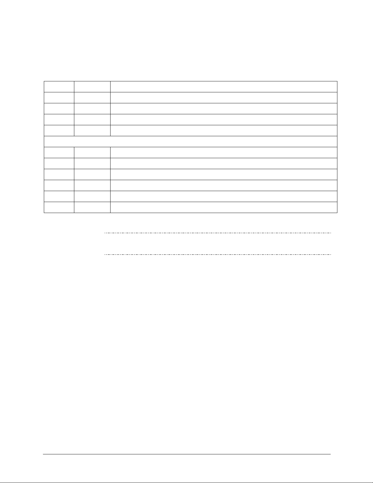
Part No. Rev Name/Description
07274 B T801 Operation manual
06843 B Menu Trees and Software Documentation (inserted as Appendix A in this manual)
07269 A Spare Parts List (located in Appendix B of this manual)
06532 C Repair Request Form (inserted as Appendix C in this manual)
Appendix D Documents:
0738001 A Interconnect List
07380 A Interconnect Diagram
05803 B SCH, PCA 05802, MOTHERBOARD, GEN-5
06698 D SCH, PCA 06697, INTRFC, LCD TCH SCRN
06882 B SCH, LVDS TRANSMITTER BOARD
06731 B SCH, AUXILLIARY-I/O BOARD
Note
We recommend that this manual be read in its entirety before any attempt is
made to operate the instrument.
ORGANIZATION
This manual is divided among three main parts and a collection of appendices at
the end:
Part I contains introductory information that includes an overview of the
analyzer, specifications, descriptions of the available options, installation and
connection instructions, and the initial calibration and functional checks.
Part II comprises the operating instructions, which include setup and calibration,
as well as remote operation, and ends with the specifics of calibrating for use in
monitoring within EPA protocol.
Part III provides detailed technical information starting with maintenance,
troubleshooting and service, frequently asked questions, principles of operation, a
primer on electrostatic discharge, and a glossary.
The appendices at the end of the manual provide support inoformation such as
version-specific software documentation, lists of spare parts* and recommended
stocking levels, and schematics.
*Part numbers do not reflect real-time updates – contact Sales or Technical
Support).
vii
Page 10
Teledyne API T801 NDIR CO2 Analyzer Operation Manual
07274B DCN6418
CONVENTIONS USED
In addition to the safety symbols as presented in the Important Safety Information
page, this manual provides special notices related to the safety and effective use
of the analyzer and other pertinent information.
Special Notices appear as follows:
ATTENTION
COULD DAMAGE INSTRUMENT AND VOID WARRANTY
This special notice provides information to avoid damage to your
instrument and possibly invalidate the warranty.
IMPORTANT
IMPACT ON READINGS OR DATA
Could either affect accuracy of instrument readings or cause loss of
data.
Note Pertinent information associated with the proper care, operation or
maintenance of the analyzer or its parts.
REVISION HISTORY
T801 Operation and Maintenance Manual, PN07274
Date Rev DCN Description
2013 January 11 B 6418 Administrative and specs updates
2011 March30 A 6009 Initial Release
viii
Page 11

07274B DCN6418
TABLE OF CONTENTS
ABOUT TELEDYNE ADVANCED POLLUTION INSTRUMENTATION (TAPI).......................................................................... i
SAFETY MESSAGES..................................................................................................................................................iii
CONSIGNES DE SÉCURITÉ ....................................................................................................................................... iv
WARRANTY.............................................................................................................................................................. v
ABOUT THIS MANUAL...............................................................................................................................................vii
REVISION HISTORY ................................................................................................................................................viii
TABLE OF CONTENTS .............................................................................................................................................. ix
List of Figures .......................................................................................................................................................xii
List of Tables .......................................................................................................................................................xiii
List of Appendices ...............................................................................................................................................xiv
PART I – GENERAL INFORMATION and Setup ...............................................................................................15
1. INTRODUCTION, FEATURES, AND OPTIONS.................................................................17
1.1. T801 Overview..............................................................................................................................................17
1.2. Features........................................................................................................................................................ 17
1.3. Options .........................................................................................................................................................18
2. SPECIFICATIONS, APPROVALS & COMPLIANCE ...........................................................21
2.1. Specifications................................................................................................................................................21
2.2. Approvals and Certifications.........................................................................................................................22
2.2.1. Safety ....................................................................................................................................................22
2.2.2. EMC....................................................................................................................................................... 22
2.2.3. Other Type Certifications....................................................................................................................... 22
3. GETTING STARTED...........................................................................................................23
3.1. Unpacking the T801 Analyzer ......................................................................................................................23
3.1.1. Ventilation Clearance ............................................................................................................................24
3.2. Instrument Layout......................................................................................................................................... 25
3.2.1. Front Panel ............................................................................................................................................25
3.2.2. Rear Panel.............................................................................................................................................29
3.2.3. Internal Chassis Layout......................................................................................................................... 31
3.3. Connections and Setup ................................................................................................................................32
3.3.1. Electrical Connections........................................................................................................................... 32
3.3.2. Pneumatic Connections ........................................................................................................................46
3.4. Startup, Functional Checks, and Initial Calibration....................................................................................... 50
3.4.1. Startup ...................................................................................................................................................50
3.4.2. Functional Checks................................................................................................................................. 52
3.4.3. Initial Calibration.................................................................................................................................... 52
Part II – OPERATING INSTRUCTIONS.............................................................................................................. 55
4. BASIC OPERATION OF THE T801 ANALYZER ...............................................................57
4.1. Overview of Operating Modes......................................................................................................................57
4.2. Sample Mode................................................................................................................................................58
4.2.1. Test Functions.......................................................................................................................................59
4.3. Calibration Mode...........................................................................................................................................60
4.4. Setup MODE.................................................................................................................................................60
4.4.1. Primary Setup Menu.............................................................................................................................. 61
4.4.2. Secondary Setup Menu (Setup>More).................................................................................................. 61
5. SETUP MENU ..................................................................................................................63
5.1. SETUP CFG: Configuration Information.................................................................................................. 63
5.2. SETUP ACAL: [NOT uSED]..................................................................................................................... 63
5.3. SETUP DAS: Internal Data Acquisition System ......................................................................................64
5.4. SETUP RNGE: Analog Output Reporting Range Configuration..............................................................64
ix
Page 12

Table of Contents Teledyne API T801 NDIR CO2 Analyzer Operation Manual
07274B DCN6418
5.4.1. Physical Range versus Analog Output Reporting Ranges.................................................................... 64
5.4.2. Analog Output Ranges for CO2 Concentration......................................................................................65
5.4.3. Reporting Range Modes .......................................................................................................................66
5.4.4. SETUP RNGE DIL: Using the Optional Dilution Ratio Feature.....................................................70
5.5. SETUP PASS: Password Protection .......................................................................................................72
5.6. SETUP CLK: Setting the Analyzer’s Internal Clock ................................................................................. 74
5.6.1. Setting the Internal Clock’s Time and Day ............................................................................................ 74
5.6.2. Adjusting the Internal Clock’s Speed.....................................................................................................74
5.7. SETUP MORE COMM: Communication Ports.....................................................................................76
5.7.1. ID (Machine Identification)..................................................................................................................... 76
5.7.2. INET (Ethernet) .....................................................................................................................................77
5.7.3. COM1[COM2] (Mode, Baude Rate and Test Port) ...............................................................................78
5.8. SETUP VARS: Variables Setup and Definition........................................................................................ 78
5.9. SETUP MORE DIAG: Diagnostics Functions.................................................................................... 81
5.9.1. Signal I/O............................................................................................................................................... 83
5.9.2. Analog Output........................................................................................................................................84
5.9.3. Analog I/O Configuration .......................................................................................................................84
5.10. SETUP MORE ALRM: Using the Gas Concentration Alarms (Option 61)....................................... 102
5.10.1. Setting the T801 Option 61 Concentration Alarm Limits................................................................... 102
6. COMMUNICATIONS SETUP AND OPERATION.............................................................105
6.1. Data Terminal/Communication Equipment (DTE DCE)..................................................................................105
6.2. Communication Modes, Baud Rate and Port Testing ................................................................................105
6.2.1. Communication Modes........................................................................................................................ 106
6.2.2. COM Port Baud Rate ..........................................................................................................................108
6.2.3. COM Port Testing................................................................................................................................109
6.3. Remote Access via the Ethernet ................................................................................................................ 110
6.3.1. Configuring the Ethernet using DHCP.................................................................................................110
6.3.2. Manually Configuring the Network IP Addresses................................................................................113
6.4. USB Port for Remote Access ..................................................................................................................... 116
6.5. Communications Protocols......................................................................................................................... 118
6.5.1. MODBUS.............................................................................................................................................118
6.5.2. Hessen ................................................................................................................................................120
7. DATA ACQUISITION SYSTEM (DAS) & APICOM .............................................................129
7.1. DAS Structure.............................................................................................................................................130
7.1.1. DAS Channels..................................................................................................................................... 130
7.1.2. Default DAS Channels.........................................................................................................................131
7.1.3. SETUP DAS VIEW: Viewing DAS Channels and Individual Records.........................................134
7.1.4. SETUP DAS EDIT: Accessing the DAS Edit Mode ....................................................................135
7.2. Remote DAS Configuration ........................................................................................................................ 148
7.2.1. DAS Configuration via APICOM..........................................................................................................148
7.2.2. DAS Configuration via Terminal Emulation Programs ........................................................................ 150
8. REMOTE OPERATION.....................................................................................................151
8.1. Computer Mode.......................................................................................................................................... 151
8.1.1. Remote Control via APICOM ..............................................................................................................151
8.2. Interactive Mode .........................................................................................................................................152
8.2.1. Remote Control via a Terminal Emulation Program............................................................................152
8.3. Remote Access by Modem.........................................................................................................................155
8.4. COM Port Password Security.....................................................................................................................157
9. CALIBRATION PROCEDURES .......................................................................................159
9.1. Before Calibration....................................................................................................................................... 160
9.1.1. Required Equipment, Supplies, and Expendables.............................................................................. 160
9.1.2. Calibration Gases................................................................................................................................ 160
9.1.3. Data Recording Devices...................................................................................................................... 161
9.2. Manual Calibration Checks and Calibration ............................................................................................... 162
9.2.1. Setup for Calibration Checks and Calibration .....................................................................................162
x
Page 13

Teledyne API T801 NDIR CO2 Analyzer Operation Manual Table of Contents
07274B DCN6418
9.2.2. Performing a Manual Calibration Check..............................................................................................163
9.2.3. Performing a Manual Calibration.........................................................................................................164
9.3. Assessing Calibration Quality.....................................................................................................................166
9.4. Calibrating the Electronic Subsystems....................................................................................................... 166
9.4.1. Pressure Calibration............................................................................................................................ 166
9.4.2. Flow Calibration...................................................................................................................................168
Part III – Maintenance and Service ...................................................................................................................169
10. MAINTENANCE SCHEDULE & PROCEDURES...........................................................171
10.1. Maintenance Schedule .............................................................................................................................171
10.2. Predictive Diagnostics ..............................................................................................................................175
10.3. Maintenance Procedures.......................................................................................................................... 175
10.3.1. Replacing the Sample Particulate Filter ............................................................................................ 175
10.3.2. Rebuilding the Sample Pump............................................................................................................176
10.3.3. Performing Leak Checks ...................................................................................................................177
10.3.4. Performing a Sample Flow Check.....................................................................................................178
10.3.5. Cleaning Exterior Surfaces of the T801 ............................................................................................178
11. TROUBLESHOOTING AND SERVICE..........................................................................179
11.1. General Troubleshooting.......................................................................................................................... 179
11.1.1. Fault Diagnosis with WARNING Messages ......................................................................................180
11.1.2. Fault Diagnosis with TEST Functions ...............................................................................................183
11.1.3. DIAG SIGNAL I/O: Using the Diagnostic Signal I/O Function ..................................................... 184
11.2. Using the Internal Electronic Status LEDs ...............................................................................................186
11.2.1. CPU Status Indicator......................................................................................................................... 186
11.2.2. Relay PCA Status Indicators .............................................................................................................186
11.3. Gas Flow Problems ..................................................................................................................................187
11.3.1. T801 Internal Gas Flow Diagrams.....................................................................................................188
11.3.2. Typical Sample Gas Flow Problems .................................................................................................188
11.4. Calibration Problems ................................................................................................................................ 190
11.4.1. Miscalibrated .....................................................................................................................................190
11.4.2. Non-Repeatable Zero and Span .......................................................................................................190
11.4.3. Inability to Span – No SPAN Button.................................................................................................. 191
11.4.4. Inability to Zero – No ZERO Button...................................................................................................191
11.5. Other Performance Problems...................................................................................................................191
11.5.1. Temperature Problems...................................................................................................................... 192
11.6. Subsystem Checkout................................................................................................................................ 192
11.6.1. AC Mains Configuration ....................................................................................................................192
11.6.2. DC Power Supply ..............................................................................................................................192
11.6.3. I2C Bus...............................................................................................................................................193
11.6.4. Touch Screen Interface .....................................................................................................................194
11.6.5. LCD Display Module.......................................................................................................................... 194
11.6.6. Relay Board.......................................................................................................................................194
11.6.7. Sensor Assembly...............................................................................................................................194
11.6.8. Pressure/Flow Sensor Assembly ......................................................................................................195
11.6.9. Motherboard ...................................................................................................................................... 196
11.6.10. CPU .................................................................................................................................................197
11.6.11. RS-232 Communications ................................................................................................................198
11.6.12. CO2 Sensor STATUS LED’s............................................................................................................199
11.7. Repair Procedures.................................................................................................................................... 199
11.7.1. Repairing Sample Flow Control Assembly........................................................................................ 199
11.7.2. Disk-On-Module Replacement Procedure ........................................................................................200
11.8. FRequently Asked Questions (FAQ’s)......................................................................................................201
11.9. Technical Assistance................................................................................................................................ 202
12. PRINCIPLES OF OPERATION ......................................................................................203
12.1. NDIR Measurement of CO2......................................................................................................................203
12.2. Operation within the T801 Analyzer .........................................................................................................204
xi
Page 14

Table of Contents Teledyne API T801 NDIR CO2 Analyzer Operation Manual
07274B DCN6418
12.2.1. Electronic Operation of the CO2 Sensor............................................................................................ 204
12.3. Pneumatic Operation................................................................................................................................ 205
12.4. Flow Rate Control..................................................................................................................................... 206
12.4.1. Critical Flow Orifice............................................................................................................................206
12.4.2. Particulate Filter.................................................................................................................................207
12.4.3. Pneumatic Sensors ...........................................................................................................................208
12.5. Electronic Operation .................................................................................................................................208
12.5.1. Overview............................................................................................................................................208
12.5.2. Central Processing Unit (CPU).......................................................................................................... 209
12.5.3. Relay Board.......................................................................................................................................210
12.5.4. Motherboard ...................................................................................................................................... 213
12.5.5. Power Supply / Circuit Breaker .........................................................................................................215
12.5.6. Front Panel Touch Screen/Display Interface ....................................................................................216
12.5.7. Software Operation............................................................................................................................218
12.5.8. Adaptive Filter....................................................................................................................................218
12.5.9. Calibration - Slope and Offset ........................................................................................................... 219
12.5.10. Temperature and Pressure Compensation .....................................................................................219
12.5.11. Internal Data Acquisition System (DAS) .........................................................................................219
13. A PRIMER ON ELECTRO-STATIC DISCHARGE .........................................................221
13.1. How Static Charges are Created..............................................................................................................221
13.2. How Electro-Static Charges Cause Damage ...........................................................................................222
13.3. Common Myths About ESD Damage....................................................................................................... 223
13.4. Basic Principles of Static Control.............................................................................................................. 224
13.4.1. General Rules....................................................................................................................................224
13.4.2. Basic Anti-ESD Procedures for Analyzer Repair and Maintenance..................................................225
Glossary............................................................................................................................................................. 229
INDEX................................................................................................................................................................ 233
LIST OF FIGURES
Figure 3-1: Front Panel Layout ......................................................................................................... 25
Figure 3-2: Display Screen and Touch Control................................................................................. 26
Figure 3-3: Display/Touch Control Screen Mapped to Menu Charts................................................ 28
Figure 3-4: Rear Panel Layout.......................................................................................................... 29
Figure 3-5: Internal Layout................................................................................................................ 31
Figure 3-6. Analog In Connector....................................................................................................... 33
Figure 3-7: Analog Output Connector............................................................................................... 34
Figure 3-8: Current Loop Option Installed ........................................................................................35
Figure 3-9: Status Output Connector................................................................................................ 37
Figure 3-10: Control Input Connector ................................................................................................. 38
Figure 3-11: Concentration Alarm Relay ............................................................................................ 39
Figure 3-12: Default Pin Assignments, Rear Panel COM Port Connectors ....................................... 41
Figure 3-13. CPU Connector Pin-Outs for RS-232 Mode................................................................... 42
Figure 3-14: Jumper and Cables for Multidrop Mode ......................................................................... 44
Figure 3-15: RS-232-Multidrop PCA Host/Analyzer Interconnect Diagram........................................ 45
Figure 3-16: Pneumatic Connections, Using Bottled Span Gas......................................................... 48
Figure 3-17: T801 Internal Gas Flow .................................................................................................. 49
Figure 3-18: Viewing and Clearing WARNING Messages ................................................................51
Figure 4-1: Front Panel Touchscreen and Display ........................................................................... 58
Figure 4-2: Viewing Test Functions ..................................................................................................59
Figure 5-1: Analog Output Connector Pin Out.................................................................................. 65
Figure 5-2: Setup for Checking / Calibrating DCV Analog Output Signal Levels ............................. 91
Figure 5-3: Setup for Checking / Calibrating Current Output Signal Levels Using an Ammeter ...... 93
xii
Page 15

Teledyne API T801 NDIR CO2 Analyzer Operation Manual Table of Contents
07274B DCN6418
Figure 5-4: Alternative Setup Using 250Ω Resistor for Checking Current Output Signal Levels..... 95
Figure 7-1: Default DAS Channel Setup......................................................................................... 133
Figure 7-2: APICOM Remote Control Program Interface ............................................................... 148
Figure 7-3: APICOM User Interface for Configuring the DAS ........................................................149
Figure 7-4: DAS Configuration Through a Terminal Emulation Program ....................................... 150
Figure 9-1: Pneumatic Connections Using Bottled Span Gas........................................................ 162
Figure 10-1: Sample Particulate Filter Assembly.............................................................................. 176
Figure 11-1: Viewing and Clearing Warning Messages ................................................................... 182
Figure 11-2: Example of Signal I/O Function.................................................................................... 185
Figure 11-3: CPU Status Indicator.................................................................................................... 186
Figure 11-4: Relay PCA Status LEDS Used for Troubleshooting..................................................... 187
Figure 11-5: T801 – Internal Gas Flow ............................................................................................. 188
Figure 11-6: Location of Diagnostic LEDs on CO2 Sensor PCA....................................................... 199
Figure 11-7: Critical Flow Restrictor Assembly / Disassembly .........................................................200
Figure 12-1. CO2 Sensor Theory of Operation .................................................................................204
Figure 12-2. CO2 Sensor PCA Layout and Electronic Connections................................................. 205
Figure 12-3: Internal Pneumatic Flow............................................................................................... 206
Figure 12-4: Flow Control Assembly & Critical Flow Orifice ............................................................. 207
Figure 12-5: T801 Electronic Block Diagram.................................................................................... 209
Figure 12-6. CPU Card ..................................................................................................................... 210
Figure 12-7: Relay PCA Layout (PN 04135)..................................................................................... 211
Figure 12-8: Relay PCA with AC Relay Retainer in Place................................................................ 212
Figure 12-9: Status LED Locations – Relay PCA ............................................................................. 213
Figure 12-10: Power Distribution Block Diagram................................................................................ 216
Figure 12-11: Front Panel and Display Interface Block Diagram .......................................................217
Figure 12-12: Basic Software Operation............................................................................................. 218
Figure 13-1: Triboelectric Charging ..................................................................................................221
Figure 13-2: Basic anti-ESD Workbench .......................................................................................... 224
LIST OF TABLES
Table 1-1. Analyzer Options ............................................................................................................ 18
Table 2-1: T801 CO2 Specifications ................................................................................................21
Table 3-1: Ventilation Clearance .....................................................................................................24
Table 3-2: Display Screen and Touch Control Description .............................................................27
Table 3-3: Rear Panel Component Descriptions............................................................................. 30
Table 3-4: Analog Input Pin Assignments .......................................................................................33
Table 3-5: Analog Output Pin-Outs ................................................................................................. 34
Table 3-6: Status Output Signals..................................................................................................... 37
Table 3-7: Control Input Signals ...................................................................................................... 38
Table 3-8: Front Panel Display during System Warm-Up ...............................................................50
Table 4-1: Analyzer Operating Modes............................................................................................. 58
Table 4-2: Test Functions Defined .................................................................................................. 60
Table 4-3: Primary Setup Mode Features and Functions................................................................ 61
Table 4-4: Secondary Setup Mode Features and Functions........................................................... 61
Table 5-1: Password Levels ............................................................................................................72
Table 5-2: Variable Names (VARS)................................................................................................. 79
Table 5-3: Diagnostic Mode (DIAG) Functions................................................................................ 81
Table 5-4: DIAG - Analog I/O Functions.......................................................................................... 84
Table 5-5: Analog Output Voltage Range Min/Max......................................................................... 86
Table 5-6: Voltage Tolerances for the TEST CHANNEL Calibration .............................................. 91
Table 5-7: Current Loop Output Check ...........................................................................................95
Table 5-8: Test Channels Functions available on the T801’s Analog Output ................................. 98
xiii
Page 16

Table of Contents Teledyne API T801 NDIR CO2 Analyzer Operation Manual
07274B DCN6418
Table 5-9: Concentration Alarm Default Settings .......................................................................... 102
Table 6-1: COM Port Communication Modes................................................................................ 106
Table 7-1: Front Panel LED Status Indicators for DAS ................................................................. 129
Table 7-2: DAS Data Channel Properties...................................................................................... 131
Table 7-3: DAS Data Parameter Functions................................................................................... 138
Table 8-1: Terminal Mode Software Commands........................................................................... 152
Table 8-2: Teledyne API Serial I/O Command Types ...................................................................153
Table 9-1: NISTSRM's Available for Traceability of CO2 Calibration Gases.................................. 161
Table 9-2: Calibration Data Quality Evaluation.............................................................................. 166
Table 10-1: T801 Maintenance Schedule........................................................................................ 173
Table 10-2: T801 Test Function Record.......................................................................................... 174
Table 10-3: Predictive Uses for Test Functions............................................................................... 175
Table 11-1: Warning Messages - Indicated Failures....................................................................... 182
Table 11-2: Test Functions - Indicated Failures .............................................................................. 184
Table 11-3: Relay PCA Watchdog LED Failure Indications ............................................................ 186
Table 11-4: Relay PCA Status LED Failure Indications ..................................................................187
Table 11-5: DC Power Test Point and Wiring Color Codes ............................................................193
Table 11-6: DC Power Supply Acceptable Levels........................................................................... 193
Table 11-7: Analog Output Test Function - Nominal Values Current Outputs ................................ 196
Table 11-8: Status Outputs Check .................................................................................................. 197
Table 12-1: Relay PCA Status LEDs............................................................................................... 212
Table 13-1: Static Generation Voltages for Typical Activities.......................................................... 222
Table 13-2: Sensitivity of Electronic Devices to Damage by ESD................................................... 222
LIST OF APPENDICES
APPENDIX A – MENU TREES AND SOFTWARE DOCUMENTATION
APPENDIX B - SPARE PARTS LIST
APPENDIX C –REPAIR QUESTIONNAIRE
APPENDIX D –ELECTRONIC SCHEMATICS
xiv
Page 17

07274B DCN6418
PART I
–
GENERAL INFORMATION AND SETUP
15
Page 18

07274B DCN6418
This page intentionally left blank.
16
Page 19

07274B DCN6418
1. INTRODUCTION, FEATURES, AND OPTIONS
1.1. T801 OVERVIEW
The Model T801 NDIR CO2 Analyzer is a microprocessor-controlled analyzer
that employs Non-Dispersive Infrared (NDIR) spectroscopy to determine the
concentration of molecular carbon dioxide (CO
through the instrument. It uses infrared absorption to measure CO
The Model T801 analyzer’s multi-tasking software gives the ability to track and
report a large number of operational parameters in real time. These readings are
compared to diagnostic limits kept in the analyzer’s memory where, should any
fall outside of those limits, the analyzer issues automatic warnings.
Built-in data acquisition capability using the analyzer's internal memory allows
logging of multiple parameters including averaged or instantaneous concentration
values, calibration data, and operating parameters such as pressure and flow rate.
Stored data are easily retrieved through rear panel communications ports via our
APICOM software, allowing operators to perform predictive diagnostics and
enhanced data analysis by tracking parameter trends. Multiple averaging periods
of one minute to 365 days are available for over a period of one year.
) in the sample gas drawn
2
.
2
1.2. FEATURES
Some of the exceptional features of your T801 NDIR CO2 Analyzer are:
Non-depleting, CO2 measurement technologies:
Microprocessor controlled for versatility
LCD Graphical User Interface with capacitive touch screen
Multi-tasking software for viewing of test variables during operation
Continuous self checking with alarms
Bi-directional USB (option), RS-232, and 10BaseT/100BaseT Ethernet ports
Front panel USB ports for peripheral devices
Digital status outputs to indicate instrument operating condition
Adaptive signal filtering to optimize response time
Internal data logging with 1 min to 365-day multiple average
Remote operation when used with Teledyne API’s APICOM software
Temperature and Pressure Compensation
Ranges, 0-1% to 0-20.0%, user adjustable
Virtually no cross-sensitivities
Rapid response times
No consumable parts
Consistent performance over time
for remote operation (optional RS-485)
17
Page 20
Introduction, Features, and Options Teledyne API T801 NDIR CO2 Analyzer Operation Manual
07274B DCN6418
1.3. OPTIONS
Table 1-1 presents the options available with the T801 analyzer. For assistance
with ordering, please contact the Sales department of Teledyne API at:
PHONE (toll free,
North America)
FAX:
PHONE (Direct):
E-MAIL:
WEB SITE
800-324-5190
858-657-9816
858-657-9800
api-sales@teledyne.com
www.teledyne-api.com
Table 1-1. Analyzer Options
Option
Pumps
Rack Mount
Kits
Carrying Strap/Handle Side-mounted strap for hand-carrying analyzer
29
Option
Number
Pumps meet all typical AC power supply standards while exhibiting same pneumatic
performance.
10A External Pump 100V - 120V @ 60 Hz N/A
10B External Pump 220V - 240V @ 50 Hz N/A
10C External Pump 220V - 240V @ 60 Hz N/A
10D External Pump 100V – 120V @ 50 Hz N/A
10E External Pump 100V @ 60 Hz N/A
14 Internal Pump N/A
13 High Voltage Internal Pump 240V @ 50Hz N/A
Options for mounting the analyzer in standard 19” racks
20A Rack mount brackets with 26 in. chassis slides N/A
20B Rack mount brackets with 24 in. chassis slides N/A
21 Rack mount brackets only (compatible with carrying strap, Option 29) N/A
23 Rack mount for external pump pack (no slides) N/A
Extends from “flat” position to accommodate hand for carrying.
Recesses to 9mm (3/8”) dimension for storage.
Can be used with rack mount brackets, Option 21.
Cannot be used with rack mount slides.
Description/Notes Reference
N/A
CAUTION - GENERAL SAFETY HAZARD
THE T801 WEIGHS ABOUT 28 POUNDS (12.7 KG). TAKE CARE TO
AVOID PERSONAL INJURY WHEN LIFTING/CARRYING THE
ANALYZER.
ALSO, DISCONNECT ALL CABLES AND TUBING FROM THE
ANALYZER BEFORE MOVING IT.
Analog Inputs w/USB port
64B
Used for connecting external voltage signals from other instrumentation (such as
meteorological instruments).
Also can be used for logging these signals in the analyzer’s internal
DAS. (See Option 64A for USB port only).
18
Sections 3.3.1.2
and 5.9.3.12
Page 21
Teledyne API T801 NDIR CO2 Analyzer Operation Manual Introduction, Features, and Options
07274B DCN6418
Option
Current Loop Analog
Outputs
41
Parts Kits Spare parts and expendables
Communication Cables For remote serial, network and Internet communication with the analyzer.
Type Description
60A RS-232
60B RS-232
60C Ethernet
60D USB
Concentration Alarm Relay Issues warning when gas concentration exceeds limits set by user.
61
RS-232 Multidrop Enables communications between host computer and up to eight analyzers.
62
USB COM Port
64A
Special Features Built in features, software activated
N/A
N/A
N/A
Option
Number
42A
42D
Description/Notes Reference
Adds isolated voltage-to-current conversion circuitry to the analyzer’s analog
outputs.
Can be configured for 0-20 mA or 4-20 mA.
May be ordered separately for any of the analog outputs.
Can be installed at the factory or retrofitted in the field.
Expendables Kit for analyzer with a pump, includes a recommended
set of expendables for one year of operation.
Expendables Kit for analyzer without a pump, includes a
recommended set of expendables for one year of operation.
Shielded, straight-through DB-9F to DB-25M cable, about
1.8 m long. Used to interface with older computers or
code activated switches with DB-25 serial connectors.
Shielded, straight-through DB-9F to DB-9F cable of about
1.8 m length.
Patch cable, 2 meters long, used for Internet and LAN
communications.
Cable for direct connection between instrument (rear
panel USB port) and personal computer.
Four (4) “dry contact” relays on the rear panel of the instrument. This
relay option is different from and in addition to the “Contact Closures”
that come standard on all TAPI instruments.
Multidrop card seated on the analyzer’s CPU card.
Each instrument in the multidrop network requires this card and a
communications cable (Option 60B).
Separate option if instrument not configured with Option 64B (analog
inputs). Disabled when using Multidrop or RS-485 communication.
Maintenance Mode Switch, located inside the instrument, places the
analyzer in maintenance mode where it can continue sampling, yet
ignore calibration, diagnostic, and reset instrument commands. This
feature is of particular use for instruments connected to Multidrop or
Hessen protocol networks.
Call Technical Support for activation.
Second Language Switch activates an alternate set of display
messages in a language other than the instrument’s default language.
Call Technical Support for a specially programmed Disk on Module containing
the second language.
Dilution Ratio Option allows the user to compensate for diluted
sample gas, such as in continuous emission monitoring (CEM) where
the quality of gas in a smoke stack is being tested and the sampling
method used to remove the gas from the stack dilutes the gas.
Call Technical Support for activation.
Section 3.3.1.4
Appendix B
Appendix B
Sections 3.3.1.8
and 6
Section 3.3.1.7
Section 3.3.1.8
Sections 3.3.1.8 and
6.4
N/A
N/A
Section 5.4.4
19
Page 22

Introduction, Features, and Options Teledyne API T801 NDIR CO2 Analyzer Operation Manual
07274B DCN6418
This page intentionally left blank.
20
Page 23

07274B DCN6418
2. SPECIFICATIONS, APPROVALS & COMPLIANCE
This section presents specifications, agency approvals, and safety compliance details.
2.1. SPECIFICATIONS
Table 2-1: T801 CO2 Specifications
Parameter Description
Ranges
Zero Noise
Span Noise
Lower Detectable Limit2 <0.04%
Zero Drift
Span Drift <± 0.1% (7 days)
Accuracy <± (1.5% of range + 2% of reading)
Temperature Coefficient <± 0.01% /°C
Rise and Fall Time <60 seconds to 95%
Pressure Range 25-31 in•Hg
Temperature Range
Humidity Range 0-95% RH, Non-Condensing
Sample Flow Rate 120ml ± 20ml/min
Dimensions (HxWxD) 7" x 17" x 23.5" (178 mm x 432 mm x 597 mm)
Weight 28 lb (12.7 kg)
AC Power
Analog Output Ranges
Recorder Offset ± 10%
Analog Output Resolution 1 part in 4096 of selected full-scale voltage
Standard I/O
Optional I/O
Alarm outputs (option) 2 opto-isolated alarm outputs with user settable alarm limits
1
As defined by the USEPA
2
Defined as twice the zero noise level by the USEPA
1
1
Min: 0-1% Full scale
Max: 0-20% Full scale (selectable, dual ranges and auto-ranging supported).
<0.02% (RMS)
<± 0.1% of reading (RMS)
<± 0.02% (24 hours)
<± 0.05% (7 days)
5 - 40C operating
100-120V 60 Hz (79W)
220-240V 50 Hz (69W)
All Outputs: 0.1 V, 1 V, 5 V or 10 V (selectable)
Three outputs convertible to 4-20 mA isolated current loop.
All Ranges with 5% under/over-range
1 Ethernet: 10/100Base-T
2 RS-232 (300 – 115,200 baud)
2 USB device ports
8 opto-isolated digital status outputs
6 opto-isolated digital control inputs
4 analog outputs
1 USB com port
1 RS485
8 analog inputs (0-10V, 12-bit)
4 digital alarm outputs
Multidrop RS232
2 4-20mA current outputs
21
Page 24

Specifications, Approvals & Compliance Teledyne API T801 NDIR CO2 Analyzer Operation Manual
07274B DCN6418
2.2. APPROVALS AND CERTIFICATIONS
The Teledyne API Model T801 NDIR CO2 Analyzer was tested and certified for Safety
and Electromagnetic Compatibility (EMC). This section presents the compliance
statements for those requirements and directives.
2.2.1. SAFETY
IEC 61010-1:2001, Safety requirements for electrical equipment for measurement,
control, and laboratory use.
CE: 2006/95/EC, Low-Voltage Directive
North American:
cNEMKO (Canada): CAN/CSA-C22.2 No. 61010-1-04
NEMKO-CCL (US): UL No. 61010-1 (2nd Edition)
2.2.2. EMC
EN 61326-1 (IEC 61326-1), Class A Emissions/Industrial Immunity
EN 55011 (CISPR 11), Group 1, Class A Emissions
FCC 47 CFR Part 15B, Class A Emissions
CE: 2004/108/EC, Electromagnetic Compatibility Directive
2.2.3. OTHER TYPE CERTIFICATIONS
For additional certifications, please contact Technical Support:
Toll-free Phone:
Phone:
Email: sda_techsupport@teledyne.com
Fax:
800-324-5190
858-657-9800
858-657-9816
22
Page 25
07274B DCN6418
3. GETTING STARTED
This section addresses the procedures for unpacking the instrument and
inspecting for damage, presents clearance specifications for proper ventilation,
introduces the instrument layout, then presents the procedures for getting started:
making electrical and pneumatic connections, and conducting an initial
calibration check.
3.1. UNPACKING THE T801 ANALYZER
CAUTION
GENERAL SAFETY HAZARD
To avoid personal injury, always use two persons to lift and carry the T801.
ATTENTION
Printed Circuit Assemblies (PCAs) are sensitive to electro-static
discharges too small to be felt by the human nervous system. Failure to
use ESD protection when working with electronic assemblies will void
the instrument warranty. Refer to Section 13 for more information on
preventing ESD damag
COULD DAMAGE INSTRUMENT AND VOID WARRANTY
e.
CAUTION!
Do not operate this instrument until you’ve removed dust plugs from SAMPLE
Note Teledyne API recommends that you store shipping containers/materials
and EXHAUST ports on the rear panel.
for future use if/when the instrument should be returned to the factory
for repair and/or calibration service. See Warranty section in this manual
and shipping procedures on our Website at http://www.teledyne-api.com
under Customer Support > Return Authorization.
23
Page 26
Getting Started Teledyne API T801 NDIR CO2 Analyzer Operation Manual
07274B DCN6418
Verify that there is no apparent external shipping damage. If damage has
occurred, please advise the shipper first, then Teledyne API.
Included with your analyzer is a printed record of the final performance
characterization performed on your instrument at the factory. This record, titled
Final Test and Validation Data Sheet (P/N 068340000) is an important quality
assurance and calibration record for this instrument. It should be placed in the
quality records file for this instrument.
With no power to the unit, carefully removed the top cover of the analyzer and
check for internal shipping damage by carrying out the following steps:
1. Carefully remove the top cover of the analyzer and check for internal shipping
damage, as follows:
a) Remove the locking screw located in the top, center of the Front panel;
b) Remove the two flat head, Phillips screws on the sides of the instrument
(one per side towards the rear);
c) Slide the cover backwards until it clears the analyzer’s front bezel;
d) Lift the cover straight up.
2. Inspect the interior of the instrument to ensure all circuit boards and other
components are in good shape and properly seated.
3. Check the connectors of the various internal wiring harnesses and pneumatic
hoses to ensure they are firmly and properly seated.
4. Verify that all of the optional hardware ordered with the unit has been
installed. These are listed on the paperwork accompanying the analyzer.
WARNING – ELECTRICAL SHOCK HAZARD
Never disconnect PCAs, wiring harnesses or electronic subassemblies
while under power.
3.1.1. VENTILATION CLEARANCE
Whether the analyzer is set up on a bench or installed into an instrument rack, be
sure to leave sufficient ventilation clearance.
Table 3-1: Ventilation Clearance
AREA
Back of the instrument 4 in.
Sides of the instrument 1 in.
Above and below the instrument 1 in.
MINIMUM REQUIRED
CLEARANCE
Various rack mount kits are available for this analyzer. See Table 1-1 of this
manual for more information.
24
Page 27
Teledyne API T801 NDIR CO2 Analyzer Operation Manual Getting Started
07274B DCN6418
3.2. INSTRUMENT LAYOUT
Instrument layout shows front panel and display, rear panel connectors, and
internal chassis layout.
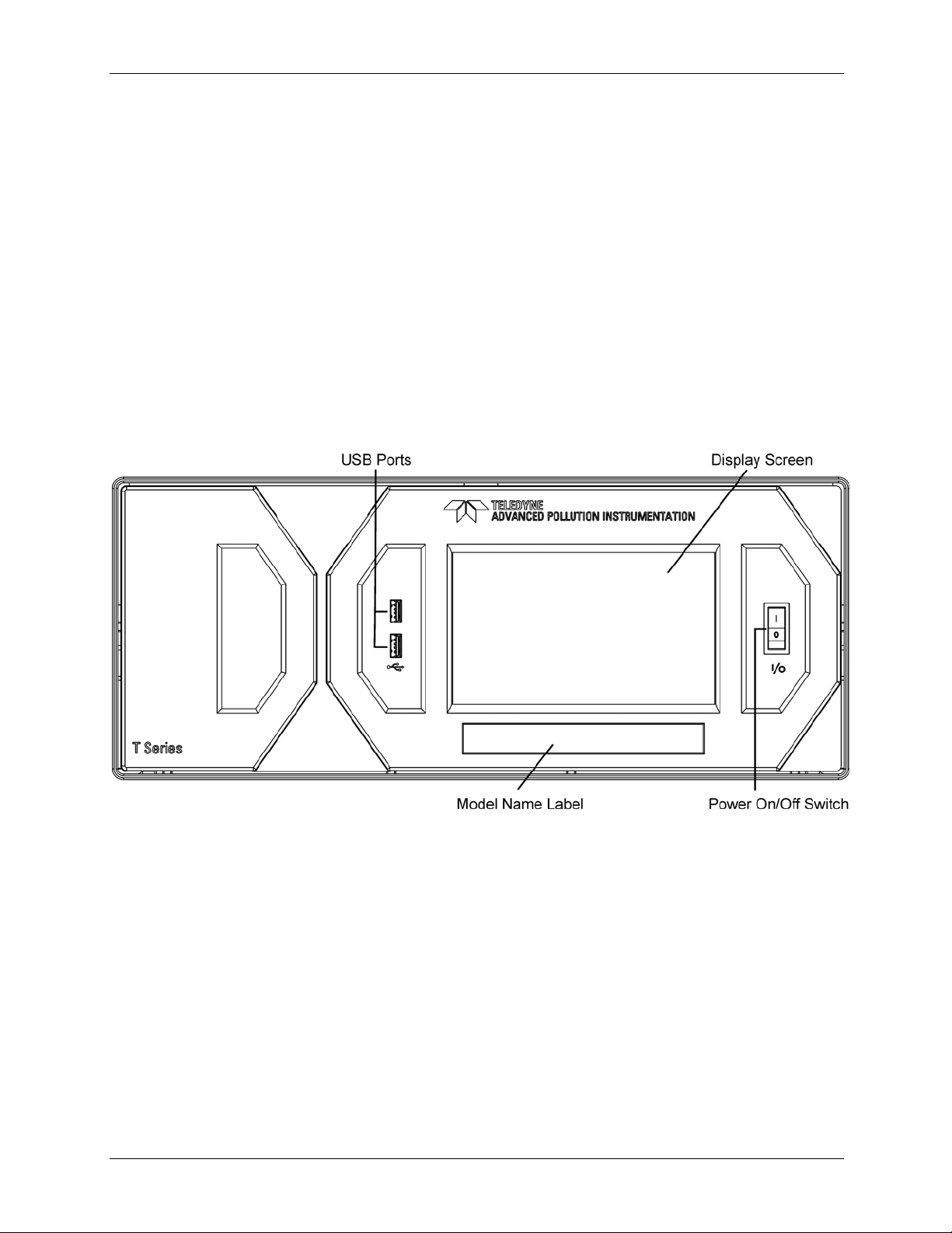
3.2.1. FRONT PANEL
Figure 3-1 shows the analyzer’s front panel layout, followed by a close-up of the
display screen in Figure 3-2, which is described in Table 3-2. The two USB ports
on the front panel are provided for the connection of peripheral devices:
plug-in mouse (not included) to be used as an alternative to the touchscreen
interface
thumb drive (not included) to download updates to instruction software
(contact TAPI Technical Support for information).
Figure 3-1: Front Panel Layout
25
Page 28
Getting Started Teledyne API T801 NDIR CO2 Analyzer Operation Manual
07274B DCN6418
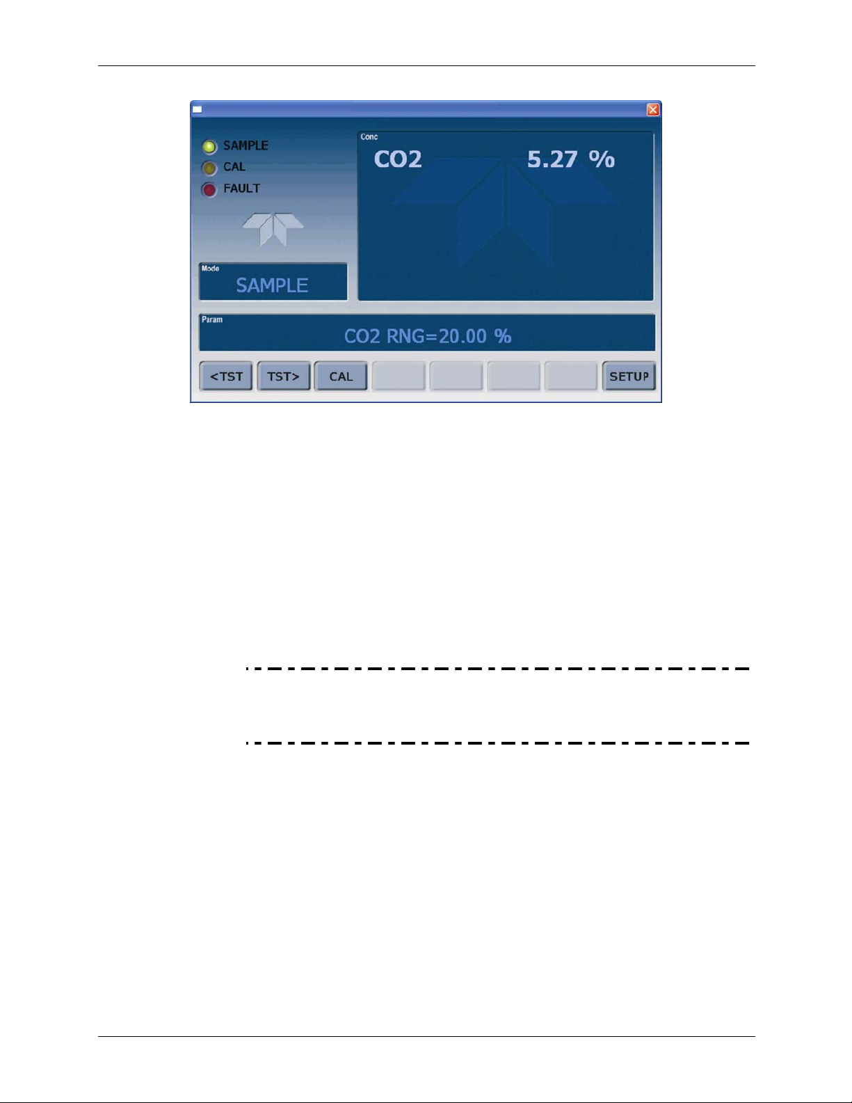
Figure 3-2: Display Screen and Touch Control
The front panel liquid crystal display screen includes touch control. Upon
analyzer start-up, the screen shows a splash screen and other initialization
indicators before the main display appears, similar to Figure 3-2 above (may or
may not display
a Fault alarm). The lights on the display screen, herein referred
to as LEDs, indicate the Sample, Calibration and Fault states; also on the screen
is the gas concentration field (Conc), which displays real-time readouts for the
primary gas and for the secondary gas if installed. The display screen also shows
what mode the analyzer is currently in, as well as messages and data (Param).
Along the bottom of the screen is a row of touch control buttons; only those that
are currently applicable will have a label. Table 3-2 provides detailed information
for each component
of the screen.
ATTENTION
COULD DAMAGE INSTRUMENT AND VOID WARRANTY
Do not use hard-surfaced instruments such as pens to operate the
control buttons.
26
Page 29
Teledyne API T801 NDIR CO2 Analyzer Operation Manual Getting Started
07274B DCN6418
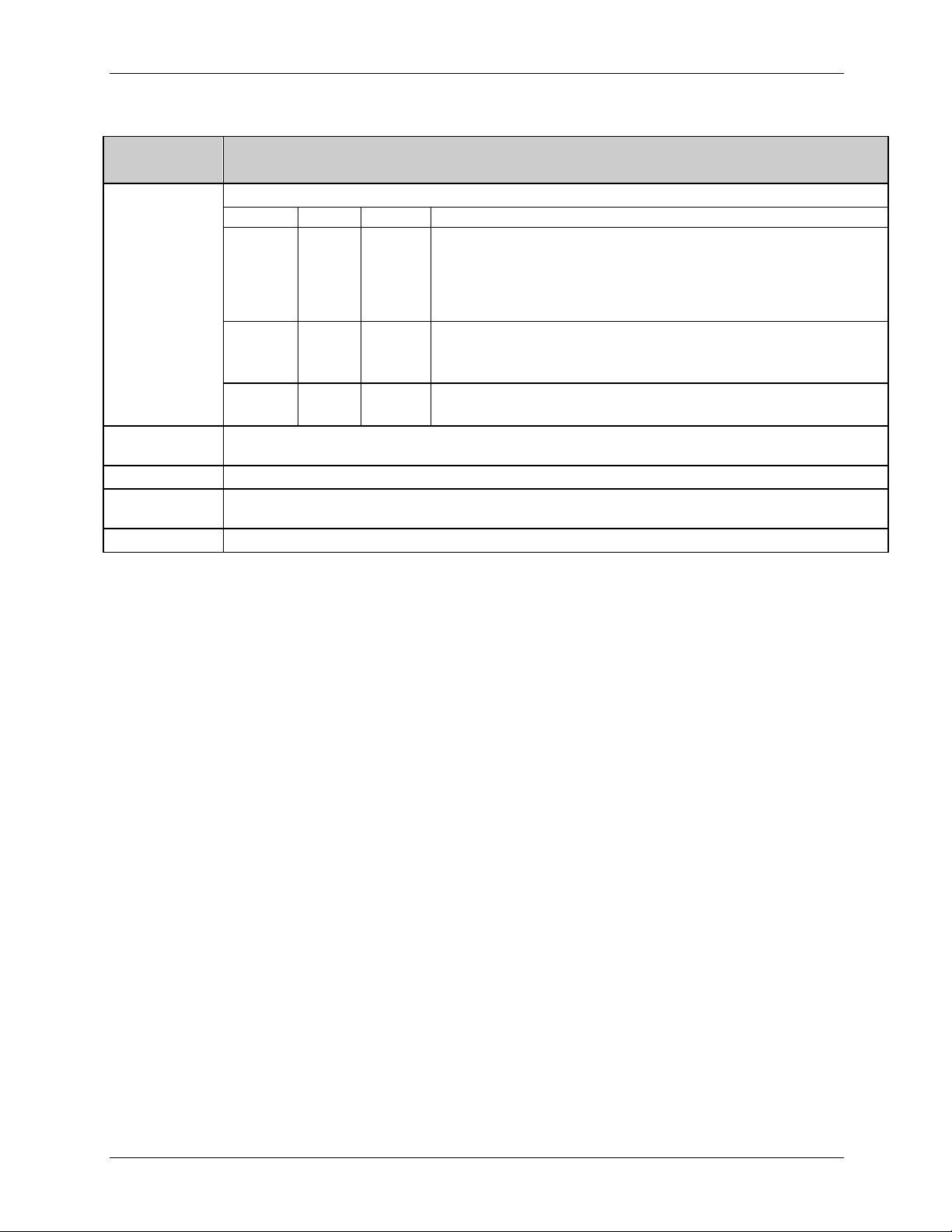
Table 3-2: Display Screen and Touch Control Description
Field Description/Function
Status
Conc
Mode Displays the name of the analyzer’s current operating mode
Param
Control Buttons Displays dynamic, context sensitive labels on each button, some blank when inactive until applicable.
LEDs indicating the states of Sample, Calibration and Fault, as follows:
Name Color State Definition
Off
On
SAMPLE Green
CAL Yellow
FAULT Red
Displays the actual concentration of the sample gas currently being measured by the analyzer in the
currently selected units of measure
Displays a variety of informational messages such as warning messages, operational data, test function
values and response messages during interactive tasks.
Blinking
Off
On
Blinking
Off
Blinking
Unit is not operating in sample mode, DAS is disabled.
Sample Mode active; Front Panel Display being updated; DAS data
being stored.
Unit is operating in sample mode, front panel display being updated,
DAS hold-off mode is ON, DAS disabled
Auto Cal disabled
Auto Cal enabled
Unit is in calibration mode
No warnings exist
Warnings exist
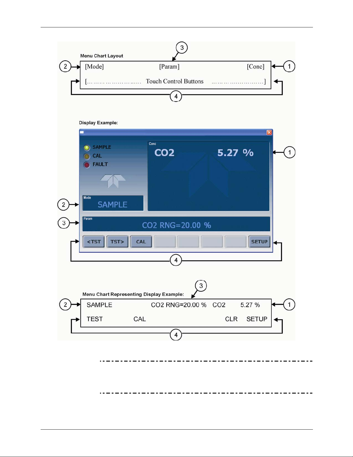
Figure 3-3 shows how the front panel display is mapped to the menu charts
illustrated in this manual. The Mode, Param (parameters), and Conc (gas
concentration) fields in the display screen are represented across the top row of
each menu chart. The eight touch control buttons along the bottom of the display
screen are represented in the bottom row of each menu chart.
27
Page 30
Getting Started Teledyne API T801 NDIR CO2 Analyzer Operation Manual
07274B DCN6418
Figure 3-3: Display/Touch Control Screen Mapped to Menu Charts
Note The menu charts in this manual contain condensed representations
of the analyzer’s display during the various operations being
described. These menu charts are not intended to be exact visual
representations of the actual display.
28
Page 31

Teledyne API T801 NDIR CO2 Analyzer Operation Manual Getting Started
07274B DCN6418
3.2.2. REAR PANEL
Figure 3-4: Rear Panel Layout
29
Page 32

Getting Started Teledyne API T801 NDIR CO2 Analyzer Operation Manual
07274B DCN6418
Table 3-3: Rear Panel Component Descriptions
Component Function
cooling fan
AC power
connector
Model/specs label
SAMPLE
EXHAUST
SPAN 1
SPAN2/VENT
ZERO AIR
RX TX
COM 2
RS-232
DCE DTE
STATUS
ANALOG OUT
CONTROL IN
ALARM
ETHERNET
ANALOG IN
USB
Information Label
Pulls ambient air into chassis through side vents and exhausts through rear.
Connector for three-prong cord to apply AC power to the analyzer.
CAUTION! The cord’s power specifications (specs) MUST comply with the power
specs on the analyzer’s rear panel Model number/Volt/Freq information label
Identifies the analyzer model number and provides power specs
Inlet connection to be used for any one of the following:
Sample gas
Span gas
Calibration gas
Zero air
Connect an exhaust gas line of not more than 10 meters long here that leads outside
the shelter or immediate area surrounding the instrument.
Not used.
Not used.
Not used.
LEDs indicate receive (RX) and transmit (TX) activity on the when blinking.
Serial communications port for RS-232 or RS-485.
Serial communications port for RS-232 only.
Switch to select either data terminal equipment or data communication equipment
during RS-232 communication.
For ouputs to devices such as Programmable Logic Controllers (PLCs).
For voltage or current loop outputs to a strip chart recorder and/or a data logger.
For remotely activating the zero and span calibration modes.
Option for concentration alarms and system warnings.
Connector for network or Internet remote communication, using Ethernet cable
Option for external voltage signals from other instrumentation and for logging these
signals
Option for direct connection to personal computer, using USB com cable.
Includes voltage and frequency specifications
30
Page 33

Teledyne API T801 NDIR CO2 Analyzer Operation Manual Getting Started
07274B DCN6418
3.2.3. INTERNAL CHASSIS LAYOUT
Figure 3-5: Internal Layout
31
Page 34

Getting Started Teledyne API T801 NDIR CO2 Analyzer Operation Manual
07274B DCN6418
3.3. CONNECTIONS AND SETUP
This section presents the electrical (Section 3.3.1) and pneumatic (Section 3.3.2)
connections for setup and preparing for instrument operation.
3.3.1. ELECTRICAL CONNECTIONS
Note To maintain compliance with EMC standards, it is required that the
cable length be no greater than 3 meters for all I/O connections,
which include Analog In, Analog Out, Status Out, Control In,
Ethernet/LAN, USB, RS-232, and RS-485.
This section presents the electrical connections for AC power and
communications.
3.3.1.1. CONNECTING POWER
WARNING - ELECTRICAL SHOCK HAZARD
High Voltages are present inside the analyzers case.
Turn OFF analyzer power before disconnecting or connecting PCAs, wiring
harnesses or electrical subassemblies.
Power connection must have functioning ground connection.
Do not defeat the ground wire on power plug.
Do not operate with cover off.
Attach the power cord to the analyzer and plug it into a power outlet capable of
carrying at least 10 A current at your AC voltage and that it is equipped with a
functioning earth ground.
CAUTION
GENERAL SAFETY HAZARD
The T801 analyzer can be configured for both 100-130 V and 210-240 V at either
47 or 63 Hz.
To avoid damage to your analyzer, make sure that the AC power voltage
matches the voltage indicated on the Analyzer’s serial number label (See
Figure 3-4) before plugging the T801 into line power.
32
Page 35

Teledyne API T801 NDIR CO2 Analyzer Operation Manual Getting Started
07274B DCN6418
3.3.1.2. CONNECTING ANALOG INPUTS (OPTION 64)
The Analog In connector is used for connecting external voltage signals from
other instrumentation (such as meteorological instruments) and for logging these
signals in the analyzer’s internal DAS. The input voltage range for each analog
input is 0-10 VDC, and the input impedance is nominally 20kΩ in parallel with
0.1µF.
Figure 3-6. Analog In Connector
Pin assignments for the Analog In connector are presented in Table 3-4.
Table 3-4: Analog Input Pin Assignments
PIN DESCRIPTION
1 Analog input # 1 AIN 1
2 Analog input # 2 AIN 2
3 Analog input # 3 AIN 3
4 Analog input # 4 AIN 4
5 Analog input # 5 AIN 5
6 Analog input # 6 AIN 6
7 Analog input # 7 AIN 7
8 Analog input # 8 AIN 8
GND Analog input Ground N/A
1
See Section 7 for details on setting up the DAS.
3.3.1.3. CONNECTING ANALOG OUTPUTS
The T801 is equipped with several analog output channels accessible through the
ANALOG OUT connector on the rear panel of the instrument. The standard
configuration for these outputs is VDC. An optional current loop output is
available for each (Section 3.3.1.4).
When the instrument is in its default configuration, channel A1 ou
that is proportional to the CO
range is configured, channels A1 and A2 each output a signal proportional to the
concentration of the sample gas. Please refer to Section 5.4.3 for details.
CO
2
DAS
PARAMETER
1
tputs a signal
concentration of the sample gas. If Dual or Auto
2
Channel A3 is not used.
33
Page 36

Getting Started Teledyne API T801 NDIR CO2 Analyzer Operation Manual
A
07274B DCN6418
Channel A4 is special. It can be set by the user (see Section 5.9.3.10) to output
any one of the parameters accessible through the <TST TST> buttons of the
unit’s front panel menu.
To access these signals attach a strip chart recorder and/or data-logger to the
appropriate analog output connections on the rear panel of the analyzer.
NALOG OUT
A1 A2 A3 A4
+ - + - + - + -
Figure 3-7: Analog Output Connector
Table 3-5: Analog Output Pin-Outs
PIN
1 V Out I Out +
2
3 V Out I Out +
4
5 V Out I Out +
6
7 V Out NA
8
ANALOG
OUTPUT
A1
A2
A3
(not used)
A4
VOLTAGE SIGNAL CURRENT SIGNAL
Ground I Out -
Ground I Out -
Ground I Out -
Ground NA
3.3.1.4. CURRENT LOOP ANALOG OUTPUTS (OPTION 41) SETUP
If your analyzer had this option installed at the factory, there are no further
connectons to be made. Otherwise, it can be installed as a retrofit for each of the
analog outputs of the analyzer . This option converts the DC voltage analog
output to a current signal with 0-20 mA output current. The outputs can be scaled
to any set of limits within that 0-20 mA range. However, most current loop
applications call for either 2-20 mA or 4-20 mA range. All current loop outputs
have a +5% over-range. Ranges with the lower limit set to more than 1 mA (e.g.,
2-20 or 4-20 mA) also have a -5% under-range.
Figure 3-8 provides installation instructions and illustrates a sample combination
of one current output a
nd two voltage outputs
configuration. The section
following this provides instructions for converting current loop analog outputs to
standard 0-to-5 VDC outputs. Information on calibrating or adjusting these
outputs can be found in Section 5.9.3.7.
34
Page 37

Teledyne API T801 NDIR CO2 Analyzer Operation Manual Getting Started
07274B DCN6418
Figure 3-8: Current Loop Option Installed
CONVERTING CURRENT LOOP ANALOG OUTPUTS TO STANDARD
VOLTAGE OUTPUTS
CAUTION – Avoid Invalidating Warranty
Servicing or handling of circuit components requires electrostatic discharge
(ESD) protection, i.e. ESD grounding straps, mats and containers. Failure to
use ESD protection when working with electronic assemblies will void the
instrument warranty. See Section 12 for more information on preventing ESD
damage.
To convert an output configured for current loop operation to the standard 0 to 5
VDC output operation:
1. Turn off power to the analyzer.
2. If a recording device was connected to the output being modified, disconnect
it.
35
Page 38

Getting Started Teledyne API T801 NDIR CO2 Analyzer Operation Manual
07274B DCN6418
3. Remove the top cover as follows:
a) Remove the set screw located at the top center of the rear panel
b) Remove the screws fastening the top cover to the unit (two per side).
c) Slide cover back.
d) Lift the cover straight up.
4. Remove the screw holding the current loop option to the motherboard.
5. Disconnect the current loop option PCA from the appropriate connector on
the motherboard (see Figure 3-8).
a)
Each conn
on the two left most pins.
b) Place the second shunt on the two pins next to it (refer to Figure 3-8 for an
example
6. Reattach the top case to the analyzer.
7. The analyzer is now ready to have a voltage-sensing, recording device
attached to that output.
ector, J19, J21 and J23, requires two shunts: Place one shunt
.
)
3.3.1.5. CONNECTING THE STATUS OUTPUTS
The status outputs report analyzer conditions via optically isolated NPN
transistors, which sink up to 50 mA of DC current. These outputs can be used to
interface with devices that accept logic-level digital inputs, such as programmable
logic controllers (PLCs). Each status bit is an open collector output that can
withstand up to 40 VDC. All of the emitters of these transistors are tied together
and connected at Pin D.
Note
Most PLCs have internal provisions for limiting the current that the input will
draw from an external device. When connecting to a unit that does not have
this feature, an external dropping resistor must be used to limit the current
through the transistor output to less than 50 mA.
At 50 mA, the transistor will drop approximately 1.2V from its collector to
emitter.
36
Page 39

Teledyne API T801 NDIR CO2 Analyzer Operation Manual Getting Started
07274B DCN6418
The status outputs are accessed via a 12-pin connector on the analyzer’s rear
panel labeled STATUS (see Figure 3-4). Pin-outs for this connector are:
STATUS
1 2 3 4 5 6 7 8 D +
SYSTEM OK
Figure 3-9: Status Output Connector
Table 3-6: Status Output Signals
Rear Panel Label Status Definition Condition
1
2
3
4
5
6
7 & 8
D
SYSTEM
OK/ALARM
CONC
VALID/CONC
INVALID
CAL MODE/
MEAS MODE
SPAN/ZERO
CAL
RANGE2 CAL
RANGE1 CAL
CO2 Sensor CAL
SPARE
EMITTER BUS The emitters of the transistors on Pins 1-8 are bussed together.
SPARE
ON if no faults are present.
OFF if alarm condition
ON if concentration measurement is valid.
OFF any time the HOLD OFF feature is active, such as during calibration or when
any faults exist invalidating the measurement.
ON whenever the instrument is in Calibration Mode
OFF when instrument in Measure Mode
ON whenever the instrument’s SPAN point is being calibrated.
OFF whenever the instrument’s ZERO point is being calibrated.
ON if unit is in high range of either the DUAL or AUTO range modes.
OFF if unit is in default low, single range mode
ON when CO2 sensor is in calibration mode.
OFF when calibration mode is exited.
CONC VALID
CAL MODE – RANGE 2
SPAN CAL / ZERO MODE
CAL MODE / MEAS MODE
+
DC POWER + 5 VDC, 300 mA source (combined rating with Control Output, if used).
Digital Ground The ground level from the analyzer’s internal DC power supplies
37
Page 40

Getting Started Teledyne API T801 NDIR CO2 Analyzer Operation Manual
07274B DCN6418
3.3.1.6. CONNECTING THE CONTROL INPUTS
If you wish to use the analyzer to remotely activate the zero and span calibration
modes, several digital control inputs are provided through a 10-pin connector
labeled CONTROL IN on the analyzer’s rear panel.
There are two methods for energizing the control inputs. The internal +5V
available from the pin labeled “+” is the most convenient method (Figure 3-10,
left). However, if full isolation is required, an external 5 VDC power supply
should
be used (Figure 3-10, right).
CONTROL IN
CONTROL IN
A B C D E F U
SPAN/ZERO CAL
CAL/SMPL MODE
RANGE SELECTION
Table 3-7: Control Input Signals
Input # Status Definition
A
B
C
D
E & F
CALIBRATION MODE or
SAMPLE MODE
REMOTE SPAN or REMOTE
ZERO CALIBRATION
RANGE2 or RANGE1
CALIBRATION
CO2 SENSOR
CALIBRATION
SPARE
Digital Ground
CO2 CAL
Local Power Connections
+
A B C D E F U
CO2 CAL
SPAN/ZERO CAL
CAL/SMPL MODE
RANGE SELECTION
5 VDC
Power Supply
-
External Power Connections
+
+
Figure 3-10: Control Input Connector
Open/Closed Condition Description
Closed: initiates Calibration mode. Front panel display Mode field will read
CAL CO2 R or CAL CO2 ZR.
Open: initiates Sample (Measure) mode. Front panel display Mode field will
read SAMPLE.
Closed: initiates remote SPAN calibration mode as part of performing a low
span calibration. Front panel display Mode field will read CAL CO2 SR.
Open: initiates remote ZERO calibration mode. Front panel display Mode
field will read ZERO MODE.
Closed: selects High Range for calibration (C2H).
Open: selects Low Range (C2L), default range in single range mode.
Closed: Initiates CO
read CAL CO2 R or CAL CO2 ZR.
Open: Exits CO
The ground level from the analyzer’s internal DC power supplies (same as
chassis ground)
sensor calibration. Front panel display Mode field will
2
sensor calibration and returns to SAMPLE mode.
2
U
External Power input
Input pin for +5 VDC required to activate Pins A – F.
Internally generated 5V DC power. To activate inputs A – F, place a jumper
+
5 VDC output
between this pin and the “U” pin. The maximum amperage through this port
is 300 mA (combined with the analog output supply, if used).
38
Page 41

Teledyne API T801 NDIR CO2 Analyzer Operation Manual Getting Started
07274B DCN6418
3.3.1.7. CONCENTRATION ALARM RELAY (OPTION 61)
The Teledyne API T-Series analyzers have an option for four (4) “dry contact”
relays on the rear panel of the instrument. This relay option is different from and
in addition to the “Contact Closures” that come standard on all TAPI instruments.
The relays have three pins that have connections on the rear panel (refer Figure
3-11). They
are a Common (C), a Normally Open (NO), and a Normally Closed
(NC) pin.
Figure 3-11: Concentration Alarm Relay
Alarm 1 “System OK 2”
Alarm 2 “Conc 1”
Alarm 3 “Conc 2”
Alarm 4 “Range Bit”
“ALARM 1” RELAY
Alarm 1 which is “System OK 2” (system OK 1, is the status bit) is in the
energized state when the instrument is “OK” & there are no warnings. If there is
a warning active or if the instrument is put into the “DIAG” mode, Alarm 1 will
change states. This alarm has “reverse logic” meaning that if you put a meter
across the Common and Normally Closed pins on the connector you will find that
it is OPEN when the instrument is OK. This is so that if the instrument should
turn off or lose power, it will change states & you can record this with a data
logger or other recording device.
“ALARM 2” RELAY AND “ALARM 3” RELAY
The “Alarm 2 Relay” on the rear panel, is associated with the “Concentration
Alarm 1” set point in the software and the “Alarm 3 Relay” on the rear panel is
associated with the “Concentration Alarm 2” set point in the software.
Alarm 2 Relay CO2 Alarm 1 = xxx %
Alarm 3 Relay CO
The Alarm 2 Relay will be turned on any time the concentration set-point is
exceeded and will return to its normal state when the concentration value goes
back below the concentration set-point.
Even though the relay on the rear panel is a NON-Latching alarm and resets when
the concentration goes back below the alarm set point, the warning on the front
panel of the instrument will remain latched until it is cleared. You can clear the
warning on the front panel by either pushing the CLR button on the front panel or
through the serial port.
Alarm 2 = xxx %
2
39
Page 42

Getting Started Teledyne API T801 NDIR CO2 Analyzer Operation Manual
07274B DCN6418
The software for this instrument is flexible enough to allow you to configure the
alarms so that you can have 2 alarm levels.
CO2 Alarm 1 = 5%
Alarm 2 = 10 %
CO
2
Another likely configuration for this would be to disable “Alarm 1” relay and set
the other concentration on the “Alarm 2” relay.
CO2 Alarm 1 = Disabled
Alarm 2 = 10%
CO
2
“ALARM 4” RELAY
This relay is connected to the “range bit”. If the instrument is configured for
“Auto Range” and the instrument goes up into the high range, it will turn this
relay on.
3.3.1.8. CONNECTING THE COMMUNICATIONS INTERFACES
The T-Series analyzers are equipped with connectors for remote communications
interfaces: Ethernet, USB, RS-232, optional RS-232 Multidrop, and optional RS-
485. In addition to using the appropriate cables (Table 1-1 describes the cable
options, 60A
through 60D), each type of communication m
ethod must be
configured using the SETUP>COMM menu (Section 5.7).
ETHERNET CONNECTION
For network or Internet communication with the analyzer, connect an Ethernet
cable from the analyzer’s rear panel Ethernet interface connector to an Ethernet
port. Although the analyzer is shipped with DHCP enabled by default, it should
be manually assigned a static IP address.
Configuration: Section 6.3
USB OPTION CONNECTION
For direct communication between the analyzer and a personal computer (PC),
connect a USB cable between the analyzer and desktop or laptop USB ports.
Setup instructions include downloading the USB driver and ensuring that the
baud rate of the PC and the analyzer match.
Configuration: Section 6.4.
Note If this option is installe
for anything other than Multidrop communication.
RS-232 CONNECTION
For RS-232 communications with data terminal equipment (DTE) or with data
communication equipment (DCE) connect the applicable cable option (Table 1-1:
either a DB9-fe
female cable, Option 60B) from the analyzer’s rear panel RS-232 port to the
male-to-DB25-male cable, Option 60A, or a DB9-female-to-DB9-
d, the rear panel COM2 port cannot be used
40
Page 43

Teledyne API T801 NDIR CO2 Analyzer Operation Manual Getting Started
07274B DCN6418
device. Adjust the DCE-DTE switch (Figure 3-4) to select DTE or DCE as
appropriate.
Configuration: Section 6.1 and Section 6.5.2 (for Hessen protocol).
IMPORTANT
IMPACT ON READINGS OR DATA
Cables that appear to be compatible because of matching
connectors may incorporate internal wiring that makes the link
inoperable. Check cables acquired from sources other than
Teledyne API for pin assignments before using.
Received from the factory, the analyzer is set up to emulate a DCE or modem,
with Pin 3 of the DB-9 connector designated for receiving data and Pin 2
designated for sending data..
COM1: RS-232 (fixed) DB-9 male connector
Baud rate: 115200 bits per second (baud)
Data Bits: 8 data bits with 1 stop bit
Parity: None
COM2: RS-232 (configurable to RS 485), DB-9 female connector
Baud rate:19200 bits per second (baud)
Data Bits: 8 data bits with 1 stop bit
Parity: None
Figure 3-12: Default Pin Assignments, Rear Panel COM Port Connectors
The signals from these two connectors are routed from the motherboard via a
wiring harness to two 10-pin connectors on the CPU card, J11 and J12.
41
Page 44

Getting Started Teledyne API T801 NDIR CO2 Analyzer Operation Manual
07274B DCN6418
Figure 3-13. CPU Connector Pin-Outs for RS-232 Mode
To assist in properly connecting the serial ports to either a computer or a modem,
there are activity indicators just above the RS-232 port. Once a cable is
connected between the analyzer and a computer or modem, both the red and
green LEDs should be on.
If the lights are not lit, use the small switch on the rear panel to switch it
between DTE and DCE modes
If both LEDs are still not illuminated, make sure the cable is properly
constructed.
42
Page 45

Teledyne API T801 NDIR CO2 Analyzer Operation Manual Getting Started
07274B DCN6418
RS-232 MULTIDROP OPTION CONNECTION
When the RS-232 Multidrop option is installed, connection adjustments and
configuration through the menu system are required. This section provides
instructions for the internal connection adjustments, then for external
connections, and ends with instructions for menu-driven configuration.
Note Because the RS-232 Multidrop option uses both the RS232 and
COM2 DB9 connectors on the analyzer’s rear panel to connect the
chain of instruments, COM2 port is no longer available for separate
RS-232 or RS-485 operation.
ATTENTION
COULD DAMAGE INSTRUMENT AND VOID WARRANTY
Printed Circuit Assemblies (PCAs) are sensitive to electro-static
discharges too small to be felt by the human nervous system. Failure to
use ESD protection when working with electronic assemblies will void
the instrument warranty. Refer to Section 13 for more information on
preventing ESD damag
In each instrument with the Multidrop option there is a shunt jumpering two pins
on the serial Multidrop and LVDS printed circuit assembly (PCA), as shown in
Figure 3-14. This shunt must be removed from all instruments except that
designated as last in th
requires powering off and opening each instrument and making the following
adjustments:
1. With NO power to the instrument, remove its top cover and lay the rear
panel open for access to the Multidrop/LVDS PCA, which is seated on the
CPU.
2. On the Multidrop/LVDS PCA’s JP2 connector, remove the shunt that jumpers
Pins 21 22 as indicated in Figure 3-14. (Do this for all but the last
ment in
instru
3. Check that the following cable connections are made in all instruments
(again refer to Figure 3-14):
J3 on the Multidrop/LVDS PCA to the CPU’s COM1 connector
(Note that the CPU’s COM2 connector is not used in Multidrop)
the chain where the shunt should remain at Pins 21 22).
e.
e multidrop chain, which must remain terminated. This
J4 on the Multidrop/LVDS PCA to J12 on the motherboard
J1 on the Multidrop/LVDS PCS to the front panel LCD
43
Page 46

Getting Started Teledyne API T801 NDIR CO2 Analyzer Operation Manual
07274B DCN6418
Figure 3-14: Jumper and Cables for Multidrop Mode
(Note: If you are adding an instrument to the end of a previously configured chain,
remove the shunt between Pins 21 22 of JP2 on the Multidrop/LVDS PCA in
the instrument that was previously the last instrument in the chain.)
4. Close the instrument.
5. Referring to Figure 3-15 use straight-through DB9 male DB9 female
cabl
es to inte
rconnect the host RS232 port to the first analyzer’s RS232 port;
then from the first analyzer’s COM2 port to the second analyzer’s RS232
port; from the second analyzer’s COM2 port to the third analyzer’s RS232
port, etc., connecting in this fashion up to eight analyzers, subject to the
distance limitations of the RS-232 standard.
6. On the rear panel of each analyzer, adjust the DCE DTE switch so that the
green and the red LEDs (RX and TX) of the COM1 connector (labeled
RS232) are both lit. (Ensure you are using the correct RS-232 cables
internally wired specifically for RS-232 communication; see Table 1-1,
“Co
mmuni
cation Cables” and the preceding subsection, “RS-232
Connection”).
44
Page 47

Teledyne API T801 NDIR CO2 Analyzer Operation Manual Getting Started
07274B DCN6418
Host
RS-232 port
Analyzer Analyzer Analyzer Last Analyzer
COM2
RS-232
COM2
RS-232
Figure 3-15: RS-232-Multidrop PCA Host
COM2
RS-232
Ensure jumper is
installed between
JP2 pins 21
last instrument of
multidrop chain.
/Analyzer Interconnect Diagram
Female DB9
Male DB9
COM2
RS-232
22 in
Note
Note
7. BEFORE communicating from the host, power on the instruments and check
that the Machine ID is unique for each (Section 5.7.1).
a. In the SET
UP Mode menu go to SETUP>MORE>COMM>ID. The default
ID is typically the model number or “0”.
b. to change the identification number, press the button below the digit to be
changed.
c. Press/select ENTER to accept the new ID for that instrument.
8. Next, in the SETUP>MORE>COMM>COM1 menu (do not use the COM2
menu for multidrop), edit the COM1 MODE parameter as follows:
press/select EDIT and set only QUIET MODE, COMPUTER MODE, and
MULTIDROP MODE to ON. Do not change any other settings.
9. Press/select ENTER to accept the changed settings, and ensure that COM1
MODE now shows 35.
10. Press/select SET> to go to the COM1 BAUD RATE menu and ensure it
reads the same for all instruments (edit as needed so that all instruments are
set at the same baud rate).
Teledyne API recommends setting up the first link, between the Host and the
first analyzer, and testing it before setting up the rest of the chain.
The (communication) Host instrument can address only one instrument at a
time, each by its unique ID (see step 7 above).
45
Page 48

Getting Started Teledyne API T801 NDIR CO2 Analyzer Operation Manual
07274B DCN6418
RS-485 CONNECTION
As delivered from the factory, COM2 is configured for RS-232 communications.
This port can be reconfigured for operation as a non-isolated, half-duplex RS-485
port. Using COM2 for RS-485 communication will disable the USB port. To
reconfigure this port for RS-485 communication, please contact the factory.
3.3.2. PNEUMATIC CONNECTIONS
This section presents information about gases and pneumatic connections.
CAUTION
GENERAL SAFETY HAZARD: CO2
While CO2 itself is not toxic, in sufficient concentrations it can be an irritant and
an asphyxiant.
Obtain a Material Safety Data Sheet for CO2 and any other hazardous components
of sample and calibration gases, and follow the prescribed safety guidelines.
Do not vent sample gases into the immediate vicinity of the analyzer nor into any
enclosed areas.
3.3.2.1. CALIBRATION GASES
ZERO GAS
Zero gas is similar in chemical composition to the earth’s atmosphere but
scrubbed of all components that might affect the analyzer’s readings. Teledyne
API recommends using pure N
sensor.
Rapid release of pure N2 gas into an enclosed space can displace oxygen, and
therefore represents an asphyxiation hazard. This may happen with few
warning symptoms.
Do not vent calibration gases into enclosed areas.
when calibrating the zero point of your CO
2
CAUTION
GENERAL SAFETY HAZARD
2
SPAN GAS
Span gas is specifically mixed to match the chemical composition of the type of
gas being measured at near full scale of the desired measurement range. Teledyne
API recommends the following when calibrating the span point of the CO
sensor:
16% CO2 in N2
Cylinders of calibrated gas traceable to NIST-Standard Reference Material
specifications (also referred to as SRMs or EPA protocol calibration gases) are
commercially available.
46
2
Page 49
Teledyne API T801 NDIR CO2 Analyzer Operation Manual Getting Started
07274B DCN6418
INTERFERENTS
Some gases, if present in the sample stream in high concentrations, could
potentially interfere with the analyzer. For example, if the Sample Gas to be
measured contains high levels of nitrogen dioxide (NO
(NO), the gases used for both the zero point calibration and the span calibration
should contain the same components in the same proportion in order to cancel
any interference effects.
3.3.2.2. BASIC PNEUMATIC CONNECTIONS
) and/or nitrous oxide
2
IMPORTANT
ATTENTION
IMPACT ON READINGS OR DATA
Sample and calibration gases should only come into contact with
Stainless Steel, PTFE (Teflon) tubing, glass or electroless nickel.
COULD DAMAGE INSTRUMENT AND VOID WARRANTY
Remove dust plugs from rear panel exhaust and supply line fittings
before powering on/operating instrument. These plugs should be
kept for reuse in the event of future storage or shipping to prevent
debris from entering the pneumatics.
CAUTION - GENERAL SAFETY HAZARD
The exhaust from the analyzer’s internal or customer supplied external
pump MUST be vented outside the immediate area or shelter surrounding
the instrument.
See Figure 3-4 for the location and descriptions of the various pneumatic
inlets/outlets referred to in this section
47
Page 50

Getting Started Teledyne API T801 NDIR CO2 Analyzer Operation Manual
07274B DCN6418
2
100%
Calibrated N
Concentration
at 16%
2
(CO
Calibrated gas
Span Concentration)
VENT
Figure 3-16: Pneumatic Connections, Using Bottled Span Gas
3.3.2.3. SAMPLE GAS SOURCE
Attach a sample inlet line to the SAMPLE inlet port. The SAMPLE input line
should not be more than two (2) meters long.
Maximum pressure of any gas at the SAMPLE inlet should not exceed 1.5 in-
hg above ambient pressure and ideally should equal ambient atmospheric
pressure.
In applications where the sample gas is received from a pressurized
manifold, a vent must be placed on the sample gas before it enters the
analyzer. Please refer to Figure 3-16.
3.3.2.4. CALIBRATION GAS SOURCES
The source of calibration gas is also attached to the SAMPLE inlet, but only
when a calibration operation is actually being performed.
Note
Zero air and span gas flows should be supplied in excess of the 120 cm
demand of the analyzer.
3.3.2.5. INPUT GAS VENTING
The span gas, zero air supply and sample gas (if pressurized) line MUST be
vented (Figure 3-16) for two reasons: in order to ensure that the gases input do
not exceed the m
aximum inlet pressure of the analyzer, and to prevent back
diffusion and pressure effects. These vents should be:
3
/min
At least 0.2m long;
No more than 2m long and;
Vented outside the shelter or at least into a well-ventilated area and away
from the immediate area surrounding the instrument
48
Page 51

Teledyne API T801 NDIR CO2 Analyzer Operation Manual Getting Started
07274B DCN6418
3.3.2.6. EXHAUST OUTLET
Attach an exhaust line to the analyzer’s EXHAUST outlet fitting. The exhaust
line should be:
PTEF tubing; minimum O.D ¼”
A maximum of 10 meters long.
Vented outside the T801 analyzer’s enclosure, preferably outside the shelter
or at least into a well-ventilated area.
Figure 3-17: T801 Internal Gas Flow
IMPORTANT
Leak Check:
Run a leak check once the appropriate pneumatic connections
have been made; check all pneumatic fittings for leaks using the
procedures defined in Section 10.3.3.
49
Page 52

Getting Started Teledyne API T801 NDIR CO2 Analyzer Operation Manual
07274B DCN6418
3.4. STARTUP, FUNCTIONAL CHECKS, AND INITIAL
CALIBRATION
IMPORTANT
IMPACT ON READINGS OR DATA
The analyzer’s cover must be installed to ensure that the
temperatures of the internal components are properly controlled.
If you are unfamiliar with the theory of operation, we recommend that you read
Section 12. For information on navigating the analyzer’s software menus, see the
menu trees de
scribed in Appendix A.1.
3.4.1. STARTUP
After the electrical and pneumatic connections are made, an initial functional
check is in order. Turn on the instrument. The pump and exhaust fan should start
immediately. The display will show a splash screen and other information during
the initialization process while the CPU loads the operating systems, the
firmware, and the configuration data.
The analyzer should automatically switch to Sample Mode after completing the
boot-up sequence and start monitoring CO
period of about 60 minutes before reliable gas measurements can be taken.
During the warm-up period the front panel display may behave as described in
Table 3-8.
Table 3-8: Front Panel Display during System Warm-Up
FIELD
Conc
(Concentration)
Mode N/A
Param
(Parameters)
STATUS LEDS
Sample Green On
Cal Yellow Off The instrument’s calibration is not enabled.
Fault Red Blinking
COLOR BEHAVIOR SIGNIFICANCE
N/A
N/A
Displays current,
compensated H
concentration
Displays blinking
“SAMPLE”
Displays menus,
parameters, and
messages.
This is normal operation, but deemed inaccurate during the
S
warm-up period.
2
Instrument is in sample mode but is still in the process of
warming up.
Use any warning messages as a means of diagnosing problems.
Unit is operating in sample mode; front panel display is being
updated.
The analyzer is warming up and hence out of specification for a
fault-free reading. various warning messages appear in the
Param field.
gas. However, there is a warm-up
2
3.4.1.1. WARNING MESSAGES
Because internal temperatures and other conditions may be outside the specified
limits during the analyzer’s warm-up period, the software will suppress most
warning conditions for 30 minutes after power up. If warning messages persist
50
Page 53

Teledyne API T801 NDIR CO2 Analyzer Operation Manual Getting Started
07274B DCN6418
after the 60-minute warm up period, investigate their cause using the
troubleshooting guidelines in Section 11.1.1.
To view and clear w
arning messages, press:
Figure 3-18: Viewing and Clearing WARNING Messages
Table 3-9 lists brief descriptions of the warning messages that may occur during
startup.
Table 3-9 : Warning Messages
MESSAGE DEFINITION
ANALOG CAL WARNING
BOX TEMP WARNING
CANNOT DYN SPAN2
CANNOT DYN ZERO3
CONFIG INITIALIZED
CO2 ALRM1 WARNING
CO2 ALRM2 WARNING
CO2 CELL TEMP WARN
DATA INITIALIZED
REAR BOARD NOT DET
RELAY BOARD WARN
SAMPLE FLOW WARN
The instrument's A/D circuitry or one of its analog outputs is not calibrated.
The temperature inside the T801 chassis is outside the specified limits.
Remote span calibration failed while the dynamic span feature was set to ON
Remote zero calibration failed while the dynamic zero feature was set to ON
Configuration was reset to factory defaults or was erased.
4
CO2 concentration alarm limit 1 exceeded
4
CO2 concentration alarm limit 2 exceeded
CO
CO2_CELL_SET variable.
DAS data storage was erased.
CPU unable to communicate with the motherboard.
CPU is unable to communicate with the relay PCA.
The flow rate of the sample gas is outside the specified limits.
sensor cell temperature outside of warning limits specified by
2
51
Page 54

Getting Started Teledyne API T801 NDIR CO2 Analyzer Operation Manual
07274B DCN6418
MESSAGE DEFINITION
SAMPLE PRESS WARN
SYSTEM RESET1
1
Does not clear after power up.
2
Clears the next time successful span calibration is performed.
3
Clears the next time successful zero calibration is performed.
4
Only active if the Concentration Alarm Option is installed
Sample gas pressure outside of operational parameters.
The analyzer was rebooted or the CPU was reset.
3.4.2. FUNCTIONAL CHECKS
After the analyzer’s components have warmed up for at least 60 minutes, verify
that the software properly supports any hardware options that were installed. For
information on navigating through the analyzer’s software menus, see the menu
trees described in Appendix A.1.
Check to make sure that the analyzer is functioning within allowable operating
parameters. Appendix C includes a list of test functions, viewable from the
analyzer’s front panel, and their expected values. These functions are also useful
tools for diagnosing performance problems (Section 11.1.2) with your analyzer.
The enclosed Final Test and Validation Data Sheet (PN 068340
values before the instrument left the factory. To view the current values of these
parameters, press the front panel button sequence for TEST functions. Remember
until the unit has completed its warm up these parameters may not have
stabilized.
000) lists these
If your local area network (LAN) is running a dynamic host configuration
protocol (DHCP) software package, the Ethernet will automatically configure its
interface with your LAN. However, it is a good idea to check these settings to
make sure that the DHCP has successfully downloaded the appropriate network
settings from your network server (see Section 6.3.1).
ur network is not running DHCP, see your network administrator or
If yo
configure the Ethernet interface manually (see Section 6.3.2).
3.4.3. INITIAL CALIBRATION
To perform the calibration you must have sources for zero air and span gas
available for input into the SAMPLE port on the back of the analyzer. See
Section 3.3.2.1 for instructions for connecting these gas sources.
The initial calibration should be carried out
as used during the analyzer’s factory calibration. This will allow you to compare
your calibration results to the factory calibration as listed on the Final Test and
Validation Data Sheet.
If both available DAS parameters for a specific gas type are being reported via
the instrument’s analog outputs e.g. CONC1 and CONC2 when the DUAL
range mode is activated, separate calibrations should be carried out for each
parameter.
using the same reporting range set up
52
Page 55

Teledyne API T801 NDIR CO2 Analyzer Operation Manual Getting Started
07274B DCN6418
Use the RNG1 button when calibrating for CONC1 (equivalent to LOW
RANGE).
Use the RNG2 button when calibrating for CONC2 (equivalent to HIGH
RANGE).
The calibration procedures assume:
that the zero point and span gases have been adjusted for known interferents
(Section 3.3.2.1)
Note
that the calibration gas will
be supplied through the SAMPLE port
that the pneumatic setup matches that described in Section 3.3.2
Perform the following outline of procedures for each sensor:
1. Verify the Reporting Range settings as presented in Section 5.4.3. We
recommend that you perform this initial checkout using the following reporting
range settings:
Mode Setting: SNGL
Analog Output Reporting Range: 16% for CO
2
2. If the Dilution Ratio Option is enabled on your T801, perform the Dilution
Ratio set up as presented in Section 5.4.4
3. Set the expe
9.2.3.1. This should be 80% of concen
cted Span Gas Concentration for CO
tration range for which the analyzer’s
as presented in Section
2
analog output range is set.
4. Perform the Zero/Span point calibration presented in Section 9.2.3.2
The analyzer is now ready for operation.
Once you have completed the above set-up procedures, please fill out the
Quality Questionnaire that was shipped with your unit and return it to
Teledyne API. This information is vital to our efforts in continuously
improving our service and our products. THANK YOU.
53
Page 56

Getting Started Teledyne API T801 NDIR CO2 Analyzer Operation Manual
07274B DCN6418
This page intentionally left blank.
54
Page 57

07274B DCN6418
PART II
–
OPERATING INSTRUCTIONS
55
Page 58

07274B DCN6418
This page intentionally left blank.
56
Page 59

07274B DCN6418
4. BASIC OPERATION OF THE T801 ANALYZER
The T801 analyzer is a computer-controlled analyzer with a dynamic menu
interface that allows all major operations to be controlled from the front panel
touchscreen through user-friendly menus (A complete set of menu trees is located
in Appendix A of this manual)
This section includes step-by-step instructions for using the display/touchscreen
to set up and operate the analyzer's CO
modes.
4.1. OVERVIEW OF OPERATING MODES
The T801 software has several operating modes (Table 6-1), and most commonly
operates in SAMPLE mode. In this mode a continuous read-out of the gas
concentration is displayed on the front panel. SAMPLE mode is used to:
measurement features and functional
2
perform calibrations
run test functions
read and clear warning messages
output analog data (when enabled)
The next most commonly used operating mode is SETUP mode, which is used
to:
perform certain configuration operations, such as programming the DAS
system or the configurable analog output channels
set up the analyzer’s serial communication channels (RS-232, RS-485,
Ethernet)
perform various diagnostic tests during troubleshooting
57
Page 60

Basic Operation of the T801 Analyzer Teledyne API T801 NDIR CO2 Analyzer Operation Manual
07274B DCN6418
Figure 4-1: Front Panel Touchscreen and Display
The mode field of the front panel display indicates to the user which operating
mode the unit is currently running.
In addition to SAMPLE and SETUP, other modes the analyzer can be operated
in are:
Table 4-1: Analyzer Operating Modes
MODE DESCRIPTION
SAMPLE Sampling normally, flashing text indicates adaptive filter is on.
SAMPLE A
CO2 M-P CAL This is the basic calibration mode of the instrument and is activated by pressing the CAL key.
SETUP [X.X]
CAL CO2 Z[type]
CAL CO2 S[type]
DIAG Mode One of the analyzer’s diagnostic modes is active (Section 5.9).
[type:]
2
3
Indicates that unit is in Sample Mode while AUTOCAL feature is active.
SETUP mode is being used to configure the analyzer. The gas measurement will continue during this
process. The revision of the T801 firmware being run will appear after the word “SETUP”
2 & 3
Unit is performing CO2 ZERO calibration procedure.
2 & 3
Unit is performing CO2 SPAN calibration procedure.
M: initiated manually by the user via the front panel touchscreen.
R: initiated remotely through the COM ports or digital control inputs
4.2. SAMPLE MODE
This is the analyzer’s standard operating mode. In this mode the instrument is
analyzing the gas in the sample chamber, calculating CO
reporting this information to the user via the front panel display, the analog
outputs and, if set up properly, the RS-232/485/Ethernet ports.
concentrations and
2
58
Page 61

Teledyne API T801 NDIR CO2 Analyzer Operation Manual Basic Operation of the T801 Analyzer
07274B DCN6418
4.2.1. TEST FUNCTIONS
A series of TEST functions are available for viewing at the front panel whenever
the analyzer is SAMPLE MODE. These functions provide information about the
various functional parameters related to the analyzer’s operation, its current
operating status, and its measurement of gas concentrations. This information is
particularly useful when troubleshooting a performance problem (see Section
11.1.2). They can also be recorded in one of the DAS channels (Section 7) for
s
data analy
To view these TEST functions, press,
is.
Figure 4-2: Viewing Test Functions
Note
Note
59
A value of “Warnings” displayed for any of the TEST functions indicates an
out-of-range reading or the analyzer’s inability to calculate it.
All pressure measurements are represented in terms of absolute pressure.
Absolute, atmospheric pressure is 29.92 in-Hg-A at sea level. It decreases
about 1 in-Hg per 300 m gain in altitude. A variety of factors such as air
conditioning and passing storms can cause changes in the absolute
atmospheric pressure.
Page 62

Basic Operation of the T801 Analyzer Teledyne API T801 NDIR CO2 Analyzer Operation Manual
07274B DCN6418
Table 4-2: Test Functions Defined
PARAMETER DISPLAY TITLE UNITS DEFINITION
Range
Stability
Sample Pressure
Sample Flow
CO2 Sensor
Slope
CO2 Sensor
Offset
CO2 Cell
Temperature
Box Temperature
Current Time
RNG
RN1
RN2
STABIL
PRES
SAMP FL
CO2 SLOPE
CO2 OFST
CO2 CELL
TEMP
BOX TEMP
TIME
%
%
In-Hg-A
3
/min
cm
- CO
- CO
C
C
-
The full scale limit at which the reporting range of the analyzer is
currently set. THIS IS NOT the Physical Range of the instrument.
See Section 5.4.1 for more information.
Standard deviation of CO
recorded every ten seconds using the last 25 data points.
The absolute pressure of the Sample gas as measured by a
pressure sensor located inside the sample chamber.
Sample mass flow rate as measured by the flow rate sensor in the
sample gas stream.
slope, computed during zero/span calibration.
2
offset, computed during zero/span calibration.
2
The current temperature of the CO
The temperature inside the analyzer chassis.
The current time. This is used to create a time stamp on DAS
readings, and by the AUTOCAL feature to trigger calibration events.
concentration readings. Data points are
2
sensor measurement cell.
2
4.3. CALIBRATION MODE
The T801 will switch into calibration mode when the user presses the CAL
button. In this mode the user can, in conjunction with introducing zero or span
gases of known concentrations into the analyzer, cause it to adjust and recalculate
the slope (gain) and offset of the its measurement range. This mode is also used
to check the current calibration status of the instrument.
Section 9 provides more information about setting up and perform
calibration operations or checks.
Note
It is recommended that span calibration be performed at 80% of full scale of
the analyzer’s currently selected reporting range.
EXAMPLE: If the reporting range is set for 0 to 10%, an appropriate span
point would be 8%.
4.4. SETUP MODE
The SETUP mode is used to configure the analyzer’s hardware and software
features, perform diagnostic procedures, gather information on the instrument’s
performance and configure or access data from the internal data acquisition
system (DAS) (Section 7). SETUP Mode has a Primary and a Secondary setup
menu.
ing standard
Note
Any changes made to a variable during one of the SETUP procedures are not
acknowledged by the instrument until the ENTR button is pressed. If the EXIT
button is pressed before the ENTR button, the analyzer will beep to notify the
user that the newly entered value has been lost.
60
Page 63

Teledyne API T801 NDIR CO2 Analyzer Operation Manual Basic Operation of the T801 Analyzer
07274B DCN6418
Setup Mode can be protected by password security through the SETUP>PASS
menu (Section 5.5) to prevent unauthorized or inadvertent configuration
adjustm
ents.
4.4.1. PRIMARY SETUP MENU
For a visual representation of the software menu trees, refer to Appendix A-1.
The areas accessible under the SETUP mode are shown below:
Table 4-3: Primary Setup Mode Features and Functions
MODE OR FEATURE
Analyzer Configuration
MENU
ITEM
CFG
DESCRIPTION
Lists key hardware and software configuration information 5.1
MANUAL
SECTION
Auto Cal Feature
Internal Data Acquisition
(DAS)
Analog Output Reporting
Range Configuration
Calibration Password
Security
Internal Clock Configuration
Advanced SETUP features
ACAL
DAS
RNGE
PASS
CLK
MORE
(Special configuration; consult factory). n/a
Used to set up the DAS system and view recorded data 7
Used to configure the output signals generated by the
instruments Analog outputs.
Turns the calibration password feature ON/OFF 5.2
Used to Set or adjust the instrument’s internal clock 5.6
This button accesses the instrument’s secondary setup
menu
4.4.2. SECONDARY SETUP MENU (SETUP>MORE)
Table 4-4: Secondary Setup Mode Features and Functions
MODE OR FEATURE
External Communication
Channel Configuration
System Status Variables
System Diagnostic Features
and
Analog Output Configuration
Alarm Limit Configuration
1
Alarm warnings only present when optional concentration alarm relay package is installed.
1
MENU
ITEM
COM
VARS
DIAG
ALRM
DESCRIPTION
Used to set up and operate the analyzer’s various external I/O
channels including RS-232, RS-485, modem communication
and/or Ethernet access.
Used to view various variables related to the instruments current
operational status
Changes made to any variable will not be recorded in the
instrument’s memory until the ENTR key is pressed.
Pressing the EXIT key ignores the new setting.
Used to access a variety of functions that configure, test or
diagnose problems with a variety of the analyzer’s basic
systems.
Most notably, the menus to configure the output signals
generated by the instruments Analog outputs are located here.
Used to turn the instrument’s two alarms on and off as well as
set the trigger limits for each.
5.4
See
Table 6-5
MANUAL
SECTION
5.7
5.8
5.9
5.10
61
Page 64

Basic Operation of the T801 Analyzer Teledyne API T801 NDIR CO2 Analyzer Operation Manual
07274B DCN6418
This page intentionally left blank.
62
Page 65

07274B DCN6418
5. SETUP MENU
The SETUP menu is used to set instrument parameters for performing
configuration, calibration, reporting and diagnostics operations.
5.1. SETUP CFG: CONFIGURATION INFORMATION
Pressing the CFG button displays the instrument’s configuration information.
This display lists the analyzer model, serial number, firmware revision, software
library revision, CPU type and other information.
Special instrument or software features or installed options may also be listed
here.
Use this information to identify the software and hardware installed in your
T801 analyzer when contacting Technical Support.
To access the configuration table, press:
Press NEXT or PREV to scroll through the
following list of Configuration information:
MODEL TYPE, NUMBER AND NAME
PART NUMBER
SERIAL NUMBER
SOFTWARE REVISION
LIBRARY REVISION
OS REVISION
SAMPLE CO2 RNG=20.00 % CO2=XXX.XX
<TST TST> CAL SETUP
SETUP X.X PRIMARY SETUP MENU
CFG ACAL DAS RNGE PASS CLK MORE EXIT
SETUP X.X SUPPORT: TELEDYNE-API.COM
PREV NEXT EXIT
Press EXIT at
any time to
return to the
SETUP menu
5.2. SETUP ACAL: [NOT USED]
ACAL on the primary SETUP menu is a special configuration. Contact factory.
63
Page 66

Setup Menu Teledyne API T801 NDIR CO2 Analyzer Operation Manual
07274B DCN6418
5.3. SETUP DAS: INTERNAL DATA ACQUISITION SYSTEM
Use the SETUP>DAS menu to capture and record data. Refer to Section 7 for
configuration and operation details.
5.4. SETUP RNGE: ANALOG OUTPUT REPORTING RANGE
CONFIGURATION
Use the SETUP>RNGE menu to configure output reporting ranges, including
scaled reporting ranges to handle data resolution challenges. This section
describes configuration for Single, Dual, and Auto Range modes.
5.4.1. PHYSICAL RANGE VERSUS ANALOG OUTPUT REPORTING
RANGES
Functionally, the T801 analyzers have one hardware PHYSICAL RANGE that is
capable of determining concentrations from 0.00 % to 20.00 % (the full range of
the sensor).
This architecture improves reliability and accuracy by avoiding the need for
extra, switchable, gain-amplification circuitry. Once properly calibrated, the
analyzer’s front panel will accurately report concentrations along the entire span
of its physical range.
Note
Because many applications use only a small part of the analyzer’s full physical
range, data resolution problems can occur for most analog recording devices. For
example, in a typical application where an T801 is being used to measure low
levels CO
instrument’s full measurement range. Unmodified, the corresponding analog
output signal would also be recorded across only 10% of the range of the
recording device.
The T801 analyzers solve this problem by allowing the user to select a scaled
reporting range for the analog outputs that only includes that portion of the
physical range relevant to the specific application.
Only this REPORTING RANGE of the analog outputs is scaled, the physical
range of the analyzer and the readings displayed on the front panel remain
unaltered.
Both the DAS values stored in the CPU’s memory and the concentration
values reported on the front panel are unaffected by the settings chosen for
the reporting range(s) of the instrument.
concentration, the full scale of expected values could be 10% of the
2
64
Page 67

Teledyne API T801 NDIR CO2 Analyzer Operation Manual Setup Menu
A
07274B DCN6418
5.4.2. ANALOG OUTPUT RANGES FOR CO2 CONCENTRATION
The analyzer has several active analog output signals accessible through a
connector on the rear panel (see Figure 3-4).
NALOG OUT
CO2 concentration outputs
A1 A2 A3 A4
+ - + - + - + -
LOW range when DUAL
or AUTO mode is selected
Not Used
Test Channel
HIGH range when DUAL
or AUTO mode is selected
Figure 5-1: Analog Output Connector Pin Out
All three outputs can be configured either at the factory or by the user for full
scale outputs of 0.1 VDC, 1VDC, 5VDC or 10VDC.
Additionally A1 and A2 may be equipped with optional 0-20 mA current loop
drivers and configured for any current output within that range (e.g. 0-20, 2-20,
4-20, etc.). (Please contact Sales for the Current Loop option) The user may also
adjust the signal level and scaling of the actual output voltage or current to match
the input requirements of the recorder or datalogger (See Section 5.9.3.9).
When the instrument is in
Auto range) output a signal proportional to the CO
its default configuration, channels A1 and A2 (Dual or
concentration of the sample
2
gas. (See Section 5.4.3). A3 is not used.
The output, l
abeled A4 is special. It can be set by the user (See Section 5.9.3.10)
to output several of the test functions accessible through the <TST TST> men
buttons.
65
u
Page 68

Setup Menu Teledyne API T801 NDIR CO2 Analyzer Operation Manual
07274B DCN6418
5.4.3. REPORTING RANGE MODES
The T801 provides three analog output range modes to choose from.
Single range (SNGL) mode sets a single maximum range for the analog
output. If single range is selected, all three outputs are slaved together and
will represent the same measurement span (e.g. 0-20 %); however, their
electronic signal levels may be configured for different ranges (e.g. 0-10
VDC vs. 0-.1 VDC).
Dual range (DUAL) allows the A1 and A2 outputs to be configured with
different measurement spans as well as separate electronic signal levels.
Auto range (AUTO) mode gives the analyzer the ability to output data via a
low range and high range. When this mode is selected the analyzer will
automatically switch between the two ranges dynamically as the
concentration value fluctuates.
Range status is also output via the external digital I/O status outputs (See Section
3.3.1.4).
To select the Analog Output Range Type press:
Upper span limit setting for the individual range modes are shared. Resetting the
span limit in one mode also resets the span limit for the corresponding range in
the other modes as follows:
SNGL DUAL AUTO
Range Range1 Low Range
Range2 High Range
66
Page 69

Teledyne API T801 NDIR CO2 Analyzer Operation Manual Setup Menu
07274B DCN6418
5.4.3.1. RNGE MODE SNGL: CONFIGURING THE T801 ANALYZER FOR SINGLE
RANGE MODE
Single Range Mode (SNGL) is the default reporting range mode for the analyzer.
When the single range mode is selected (SNGL), all concentration outputs (A1,
A2) are slaved together and set to the same reporting range limits (e.g. 0- 20.00
%). The span limit of this reporting range can be set to any value within the
physical range of the analyzer.
Although the outputs share the same concentration reporting range, the electronic
signal ranges of the analog outputs may still be configured for different values
(e.g. 0-5 VDC, 0-10 VDC, etc; see Section 5.9.3.1)
To select SNGL range m
ode and to set the upper limit of the range, press:
(The ACAL submenu in the Primary Setup Menu is a special configuration; consult factory).
67
Page 70

Setup Menu Teledyne API T801 NDIR CO2 Analyzer Operation Manual
07274B DCN6418
5.4.3.2. RNGE MODE DUAL: CONFIGURING THE T801 ANALYZER FOR DUAL
RANGE MODE
Selecting the DUAL range mode allows the A1 and A2 outputs to be configured
with different reporting ranges. The analyzer software calls these two ranges
RNG1 (low) and RNG2 (high).
The C2L RANGE 1 setting corresponds with the analog output labeled A1 on
the rear panel of the instrument.
The C2H RANGE 2 setting corresponds with the A2 output.
In DUAL range mode the RANGE test function displayed on the front panel will
be replaced by two separate functions:
CO2 RN1: The range setting for the A1 output.
CO2 RN2: The range setting for the A2 output.
To select the DUAL range mode press following menu button sequence:
When the instrument’s range mode is set to Dual the concentration field in the
upper right hand corner of the display alternates between displaying the low
range value and the high range value. The concentration that would be displayed,
is identified as follows: ”C2L” = LOW (or A1) and ”C2H” = HIGH (or A2).
Note
68
In DUAL range mode C2L and C2H have separate slopes and offsets for
computing CO2 concentrations. The two ranges must be independently
calibrated.
Page 71

Teledyne API T801 NDIR CO2 Analyzer Operation Manual Setup Menu
07274B DCN6418
To set the upper range limit for each independent reporting range, press:
(The ACAL submenu in the Primary Setup Menu is a special configuration; consult factory).
5.4.3.3. RNGE MODE AUTO: CONFIGURING THE T801 ANALYZER FOR AUTO
RANGE MODE
In AUTO range mode, the analyzer automatically switches the reporting range
between two user-defined ranges (low and high).
The unit will switch from low range to high range when the CO2 concentration
exceeds 98% of the low range span.
The unit will return from high range back to low range once the CO
concentration falls below 75% of the low range span.
In AUTO Range mode the instrument reports the same data in the same range on
both the A1 and A2 outputs and automatically switches both outputs between
ranges as described above.
Also the RANGE test function displayed on the front panel will be replaced by
two separate functions:
CO2 RNG1: The LOW range setting for all analog outputs.
CO2 RNG2: The HIGH range setting for all analog outputs.
The high/low range status is also reported through the external, digital status bits
(See Section 3.3.1.4).
2
69
Page 72

Setup Menu Teledyne API T801 NDIR CO2 Analyzer Operation Manual
07274B DCN6418
To set individual ranges press the following menu sequence:
(The ACAL submenu in the Primary Setup Menu is a special configuration; consult factory).
5.4.4. SETUP RNGE DIL: USING THE OPTIONAL DILUTION RATIO
FEATURE
This feature is an optional software utility that is used to compensate for any
dilution of the sample gas that may occur before it enters the sample inlet.
Typically this occurs in continuous emission monitoring (CEM) applications
where the sampling method used to remove the gas from the stack, dilutes the
sample.
To set up and use the dilution ratio option:
1. In the DIAG menu, use the 929 password and navigate to Factory Options
and enable the Dilution Ratio feature. (Press ENTER to save setting, and
then return to SETUP menu).
70
Page 73

Teledyne API T801 NDIR CO2 Analyzer Operation Manual Setup Menu
07274B DCN6418
2. Select the reporting range mode and set the reporting range upper limit (see
Section 5.4.3).
3. Ensu
re that the upper span limit entered for the reporting range is the
maximum expected concentration of the non-diluted gas.
4. Set the dilution factor as a gain (e.g., a value of 20 means 20 parts diluent
and 1 part of sample gas):
5. Calibrate the analyzer.
Make sure that the calibration span gas is either supplied through the
same dilution system as the sample gas or has an appropriately lower
actual concentration.
EXAMPLE: If the reporting range limit is set for 20 % and the dilution ratio
of the sample gas is 20, either:
a span gas with the concentration of 20 % can be used if the span gas
passes through the same dilution steps as the sample gas, or;
a 1 % span gas must be used if the span gas IS NOT routed through the
dilution system.
71
Page 74

Setup Menu Teledyne API T801 NDIR CO2 Analyzer Operation Manual
07274B DCN6418
5.5. SETUP PASS: PASSWORD PROTECTION
The menu system provides password protection of the calibration and setup
functions to prevent unauthorized adjustments. When the passwords have been
enabled in the PASS menu item, the system will prompt the user for a password
anytime a password-protected function (e.g., SETUP) is selected. This allows
normal operation of the instrument, but requires the password (101) to access to
the menus under SETUP. When PASSWORD is disabled (SETUP>PASS>OFF),
any operator can enter the Primary Setup (SETUP) and Secondary Setup
(SETUP>MORE) menus. Whether PASSWORD is enabled or disabled, a
password (default 818) is required to enter the VARS or DIAG menus in the
SETUP>MORE menu.
Table 5-1: Password Levels
PASSWORD LEVEL MENU ACCESS ALLOWED
Null (000) Operation All functions of the main menu (top level, or Primary, menu)
101
818
Configuration/Maintenance
Configuration/Maintenance
Access to Primary and Secondary SETUP Menus when PASSWORD is
enabled
Access to Secondary SETUP Submenus VARS and DIAG whether
PASSWORD is enabled or disabled.
IMPORTANT
IMPACT ON READINGS OR DATA
There are more VARS available when using the password, 929, for
configuration. Use caution when pressing any buttons while in this
setup. Any changes made may alter the performance of the
instrument or cause the instrument to not function properly. To
discard an accidental change to a setup parameter, press EXIT.
To enable or disable passwords, press:
72
Page 75

Teledyne API T801 NDIR CO2 Analyzer Operation Manual Setup Menu
07274B DCN6418
Example: If all passwords are enabled, the following menu sequence would be
required to enter the SETUP menu:
SAMPLE CO2 RNG=20.00 % CO2=XXX.XX
<TST TST> CAL SETUP
Press individual
buttons to set
number
EXAMPLE: This
password enables the
SETUP mode
Note
SYSTEM ENTER PASSWORD:0
0 0 0 ENTR EXIT
SYSTEM ENTER PASSWORD:101
1 0 1 ENTREXIT
Analyzer enters selected menu
When PASSWORD ENABLE is set to OFF, the instrument still prompts for a
password when entering the VARS and DIAG menus, but it displays the
default password (818). Press ENTR to continue.
73
Page 76

Setup Menu Teledyne API T801 NDIR CO2 Analyzer Operation Manual
07274B DCN6418
5.6. SETUP CLK: SETTING THE ANALYZER’S INTERNAL
CLOCK
The analyzer has an internal clock for setting the time and day; it’s speed can be
adjusted to compensate for faster or slower CPU clocks. Press SETUP>CLK to
access the clock.
5.6.1. SETTING THE INTERNAL CLOCK’S TIME AND DAY
The T801 has a time of day clock that supports the time of day TEST function,
the time stamps for the DAS feature and most COM port messages.
To set the clock’s time and day, press:
SAMPLE CO2 RNG=20.00 % CO2=XXX.XX
<TST TST> CAL SETUP
SETUP X.X PRIMARY SETUP MENU
CFG ACAL DAS RNGE PASS CLK MORE EXIT
SETUP X.X TIME-OF-DAY CLOCK
TIME DATE EXIT
SETUP X.X TIME: 12:00
1 2 :0 0 ENTR EXIT
Toggle these
HOUR MINUTE DAY MONTH YEAR
SETUP X.X TIME: 22:30
2 2:3 0 ENTREXIT
(The ACAL submenu in the Primary Setup Menu is a special configuration; consult factory).
buttons to enter
current hour
SETUP X.X TIME-OF-DAY CLOCK
TIME DATE EXIT
SETUP X.X DATE: 01-OCT-09
0 1OCT0 9 ENTREXIT
SETUP X.X DATE: 15-OCT-09
1 5OCT0 9 ENTREXIT
Toggle these buttons
to change day, month
and/or year.
EXIT returns to
SETUP X.X
display
5.6.2. ADJUSTING THE INTERNAL CLOCK’S SPEED
In order to compensate for CPU clocks that run faster or slower, you can adjust a
variable called CLOCK_ADJ to speed up or slow down the clock by a fixed
amount every day.
74
Page 77

Teledyne API T801 NDIR CO2 Analyzer Operation Manual Setup Menu
07274B DCN6418
The CLOCK_ADJUST variable is accessed via the VARS submenu: To change
the value of this variable, press:
(The ACAL submenu in the Primary Setup Menu is a special configuration; consult factory).
75
Page 78

Setup Menu Teledyne API T801 NDIR CO2 Analyzer Operation Manual
07274B DCN6418
5.7. SETUP MORE COMM: COMMUNICATION PORTS
This section introduces the communications setup menu; Section 6 provides the
setup instructions and operation information. To arrive at the communications
menu, press SETUP>ENTR>MORE>COMM.
5.7.1. ID (MACHINE IDENTIFICATION)
Each type of Teledyne API’s analyzer is configured with a default ID code. The
default ID code for T801 analyzers is either 0 or 801.
The ID number is only important if more than one of the same model analyzer is
connected to the one communications channel, such as when several analyzers
are:
in an RS-232 multidrop chain (Section 3.3.1.8)
on the same Ethernet LAN (Section 6.3)
whe
when applying HESSEN protocol (S
n applying MODBUS protocol (Section 6.5.1)
ection 6.5.2)
If two analyzers of the same model type are used on one channel, the ID codes of
one or both of the instruments needs to be changed.
76
Page 79

Teledyne API T801 NDIR CO2 Analyzer Operation Manual Setup Menu
07274B DCN6418
To edit the instrument’s ID code, press:
The ID can also be used for to identify any one of several analyzers attached to
the same network, e.g., by location number, company asset number, etc.).
(The ACAL submenu in the Primary Setup Menu is a special configuration; consult factory).
5.7.2. INET (ETHERNET)
Use SETUP>COMM>INET to configure Ethernet communications, whether
manually or via DHCP. Please see Section 6.3 for configuration details.
77
Page 80

Setup Menu Teledyne API T801 NDIR CO2 Analyzer Operation Manual
07274B DCN6418
5.7.3. COM1[COM2] (MODE, BAUDE RATE AND TEST PORT)
Use the SETUP>COMM>COM1[COM2] menus to:
configure communication modes (Section 6.2.1)
view/set the baud rate (Section 6.2.2)
test the con
nections of the com ports (Section 6.2.3).
Configuring COM1 or COM2 requires setting the DCE DTE switch on the rear
panel. Section 6.1 provides DCE DTE information.
5.8. SETUP VARS: VARIABLES SETUP AND DEFINITION
Through the SETUP>MORE>VARS menu there are several user-adjustable
software variables, which define certain operational parameters. Usually, these
variables are automatically set by the instrument’s firmware, but can be manually
re-defined using the VARS menu.
Table 5-2 lists variables that are available within the 818 password protected
level. See Appendix A2
accessible through the remote interface.
for a detailed listing of the T801 variables that are
78
Page 81

Teledyne API T801 NDIR CO2 Analyzer Operation Manual Setup Menu
07274B DCN6418
Table 5-2: Variable Names (VARS)
0 Sec/Day
VARS
Default
settings
15 min.
ON
[OFF]
[OFF]
AUTO
OFF
NO. VARIABLE DESCRIPTION
Changes the Internal Data Acquisition System (DAS) HOLD
OFF timer:
DAS_HOLD_OFF
0
1
2
3
4
5
6
TPC_ENABLE
DYN_ZERO
Special configuration;
consult factory
DYN_SPAN
Special configuration;
consult factory
CONC_PRECISION
CLOCK_ADJ
SERVICE_CLEAR
No data are stored in the DAS channels during situations
when the software considers the data to be questionable
such as during warm up or just after the instrument returns
from one of its calibration modes to SAMPLE Mode.
NOTE: It is strongly recommended that this variable
NOT be changed.
ON enables, OFF disables temperature and pressure
compensation
[Automatically adjusts offset and slope of the CO2 response
when performing a zero point calibration during an AutoCal.]
[Automatically adjusts offset and slope of the CO
when performing a zero point calibration during an AutoCal.]
Allows the user to set the number of significant digits to the
right of the decimal point display of concentration and
stability values.
Adjusts the speed of the analyzer’s clock. Choose the +
sign if the clock is too slow, choose the - sign if the clock is
too fast. Toggle keys to change the number of seconds.
Pressing the OFF button to display SERVICE_CLEAR:ON,
followed by pressing ENTR resets the service interval timer
and returns this Var back to its default setting, ready for the
next reset.
response
2
ALLOWED
SETTINGS
May be set for
intervals
between
0.5 – 20 min
ON, OFF
[ON, OFF]
[ON, OFF]
AUTO, 1, 2,
3, 4
-60 to +60
s/day
ON, OFF
TIME_SINCE_SVC
7
SVC_INTERVAL
8
Displays time in hours since last service (restarted by the
SERVICE_CLEAR Variable).
Sets the interval in hours between service reminders.
0-50,000
0-100,000
0
0
79
Page 82

Setup Menu Teledyne API T801 NDIR CO2 Analyzer Operation Manual
07274B DCN6418
To access and navigate the VARS menu, use the following key sequence.
SAMPLE CO2 RNG=20.00 % CO2=XXX.XX
<TST TST> CAL MSG SETUP
SETUP X.X PRIMARY SETUP MENU
CFG ACAL DAS RNGE PASS CLK MORE EXIT
Toggle these
buttons to enter
the correct
PASSWORD
SETUP X.X SECONDARY SETUP MENU
COMM VARS DIAG EXIT
SETUP X.X ENTER PASSWORD:818
8 1 8 ENTR EXIT
SETUP X.X 0) DAS_HOLD_OFF=15.0 Minutes
PREV NEXT JUMP EDIT PRNT EXIT
SETUP X.X 2) TPC_ENABLE=ON
PREV NEXT JUMP EDIT PRNT EXIT
SETUP X.X 3) DYN_ZERO=OFF
PREV NEXT JUMP EDIT PRNT EXIT
SETUP X.X 4) DYN_SPAN=OFF
PREV NEXT JUMP EDIT PRNT EXIT
SETUP X.X 5) CONC_PRECISION=AUTO
PREV NEXT JUMP EDIT PRNT EXIT
SETUP X.X 6) CLOCK_ADJUST=0 Sec/Day
PREV NEXT JUMP EDIT ENTR EXIT
In all cases:
EXIT discards the new
setting
ENTR accepts the
new setting
SETUP X.X DAS_HOLD_OFF=15.0 Minutes
1 5 .0 ENTR EXIT
SETUP X.X TPC_ENABLE:ON
ON ENTR EXIT
SETUP X.X CONC_PRECISION=AUTO
AUTO1234 ENTREXIT
SETUP X.X CLOCK_ADJUST=0 Sec/Day
+0 0 ENTR EXIT
Toggle these buttons to set
the DAS HOLDOFF time
period in minutes
(MAX = 20 minutes).
Toggle to turn on or turn
OFF temperature pressure
compensation.
Use these buttons to select
the precision of the gas
concentration display
Enter sign and number of
seconds per day the clock
gains (-) or loses(+)
80
Page 83

Teledyne API T801 NDIR CO2 Analyzer Operation Manual Setup Menu
07274B DCN6418
5.9. SETUP MORE DIAG: DIAGNOSTICS FUNCTIONS
A series of diagnostic tools is grouped together under the
SETUPMOREDIAG menu. These tools can be used in a variety of
troubleshooting and diagnostic procedures and are referred to in many places of
the maintenance and trouble-shooting sections of this manual.
The various operating modes available under the DIAG menu are:
Table 5-3: Diagnostic Mode (DIAG) Functions
DIAG SUBMENU SUBMENU FUNCTION
Allows observation of all digital and analog signals in
the instrument. Allows certain digital signals such as
SIGNAL I/O
heaters to be toggled ON and OFF.
parameters are dependent on firmware revision, (see
Appendix A).
When entered, the analyzer performs an analog
ANALOG OUTPUT
output step test. This can be used to calibrate a
chart recorder or to test the analog output accuracy.
This submenu allows the user to configure the
analyzer’s analog output channels, including
choosing what parameter will be output on each
ANALOG I/O
CONFIGURATION
channel. Instructions that appear here allow
adjustment and calibration of the voltage signals
associated with each output as well as calibration of
the analog to digital converter circuitry on the
motherboard.
PRESSURE
CALIBRATION
FLOW
CALIBRATION
This function is used to calibrate the Sample
1
Pressure sensor.
This function is used to calibrate the sample gas
1
flow.
These
Front Panel Mode
Indicator
DIAG I/O
DIAG AOUT
DIAG AIO
DIAG PCAL
DIAG FCAL
MANUAL
SECTION
11.1.3
11.6.9.2
5.9.3
9.4.1
9.4.2
TEST CHAN
OUTPUT
1
These settings are retained after exiting DIAG mode.
Selects one of the available test channel signals to
output over the A4 analog output channel.
DIAG TCHN
5.9.3.10
81
Page 84

Setup Menu Teledyne API T801 NDIR CO2 Analyzer Operation Manual
07274B DCN6418
To access the DIAG functions press the following menu sequence:
<TST TST> CAL MSG
SETUP X.X
CFG DAS ACAL RNGE PASS CLK EXIT
SETUP X.X
COMM VARS EXIT
SETUP X.X
EXIT
returns to the
Activates the
selected
submenu
PREV
PREV
PREV
PREV
PREV
PREV
(The ACAL submenu in the Primary Setup Menu is a special configuration; consult factory).
82
Page 85

Teledyne API T801 NDIR CO2 Analyzer Operation Manual Setup Menu
07274B DCN6418
5.9.1. SIGNAL I/O
The signal I/O diagnostic mode allows a user to review and change the digital and
analog input/output functions of the analyzer. It can also be used for
troubleshooting purposes (Section 11.1.3). Refer to Appendix A for a complete
list of the para
meters available for review under this menu.
IMPORTANT
IMPACT ON READINGS OR DATA
Any changes of signal I/O settings will remain in effect only until the
signal I/O menu is exited. Exceptions are the ozone generator
override and the flow sensor calibration, which remain as entered
when exiting.
Access the Signal I/O test mode from the DIAG Menu and press ENTR to access
its parameters:
DIAG SIGNAL I / O
PREV NEXT JUMP ENTR EXIT
DIAG I / O 0) EXT_ZERO_CAL=OFF
PREV NEXT JUMP PRNT EXIT
EXAMPLE
DIAG I / O JUMP TO: 12
1 2 ENTR EXIT
Press NEXT & PREV to
move between signal
types.
Press JUMP to go
directly to a specific
signal
See Appendix A-4 for
a complete list of
available SIGNALS
EXAMPLE:
Enter 12 to Jump to
12) ST_SYSTEM_OK=ON
DIAG I / O 12) ST_SYSTEM_OK = ON
PREV NEXT JUMP ON PRNT EXIT
Toggle ON/(OFF) button to
change status.
Pressing the PRNT button will send a formatted
printout to the serial port and can be captured
with a computer or other output device.
Exit to return
to the
DIAG menu
83
Page 86

Setup Menu Teledyne API T801 NDIR CO2 Analyzer Operation Manual
07274B DCN6418
5.9.2. ANALOG OUTPUT
The T801 analyzer comes equipped with four analog outputs.
The first two analog output (A1 & A2) signals represent the currently
measured CO
The third analog output (A3) is not used.
The fourth output (A4) outputs a signal that can be set to represent the
current value of one of several test functions (see Table 5-8).
concentration (see Section 5.4.2).
2
5.9.3. ANALOG I/O CONFIGURATION
The following lists the analog I/O functions that are available in the T801
analyzer.
Table 5-4: DIAG - Analog I/O Functions
SUB MENU FUNCTION
Initiates a calibration of the A1, A2, A3 and A4 analog output channels that determines the
AOUT
CALIBRATED
CONC_OUT_1
CONC_OUT_2
TEST OUTPUT
slope and offset inherent in the circuitry of each output.
These values are stored in the memory and applied to the output signals by the CPU
automatically.
Sets the basic electronic configuration of the A1 output (CO2 Concentration).
There are four options:
RANGE
REC OFS: Allows them input of a DC offset to let the user manually adjust the output
level
AUTO CAL: Enables / Disables the AOUT CALIBRATION Feature
CALIBRATED: Performs the same calibration as AOUT CALIBRATED, but on this one
channel only.
Same as for CONC_OUT_1 but for analog channel A2 and only if Auto or Dual range is
selected (CO
Not used.
Same as for CONC_OUT_1 but for analog channel A4 (TEST CHANNEL)
1
: Selects the signal type (voltage or current loop) and level of the output
high range, RNG2)
2
AIN
CALIBRATED
XIN1
.
.
.
XIN8
1
Any changes made to RANGE or REC_OFS require recalibration of this output.
Initiates a calibration of the A-to-D Converter circuit located on the Motherboard.
For each of 8 external analog inputs channels, shows the gain, offset, engineering
units, and whether the channel is to show up as a Test function.
84
Page 87

Teledyne API T801 NDIR CO2 Analyzer Operation Manual Setup Menu
07274B DCN6418
To access the ANALOG I/O CONFIGURATION sub menu, press:
SAMPLE CO2 RNG=20.00 % CO2=XXX.XX
<TST TST> CAL MSG SETUP
SETUP X.X PRIMARY SETUP MENU
CFG ACAL DAS RNGE PASS CLK MORE EXIT
SETUP X.X SECONDARY SETUP MENU
COMM VARS DIAG EXIT
SETUP X.X ENTER PASSWORD:818
Toggle these
buttons to enter
the correct
PASSWORD
8 1 8 ENTR EXIT
DIAG SIGNAL I/O
NEXT ENTR EXIT
Continue pressing NEXT until ...
AIO Configuration Submenu
DIAG ANALOG I/O CONFIGURATION
PREV NEXT ENTR EXIT
DIAG AIO AOUTS CALIBRATED: NO
SET> CAL EXIT
DIAG AIO CONC_OUT_1: 5V, OVR, CAL
<SET SET> EDIT EXIT
DIAG AIO CONC_OUT_2: 5V, OVR, CAL
<SET SET> EDIT EXIT
DIAG AIO CONC_OUT_3: 5V, OVR, CAL
<SET SET> EDIT EXIT
DIAG AIO TEST_OUTPUT: 5V,OVR, CAL
<SET SET> EDIT EXIT
Adjusts the signal output
for Analog Output A1
Adjusts the signal output
for Analog Output A2
Adjusts the signal output
for Analog Output A3
(O2Sensor Only)
Selects the parameter to be
output on the TEST channel and
adjusts its signal output
DIAG AIO AIN CALIBRATED: YES
<SET CAL EXIT
(The ACAL submenu in the Primary Setup Menu is a special configuration; consult factory).
85
Page 88

Setup Menu Teledyne API T801 NDIR CO2 Analyzer Operation Manual
07274B DCN6418
5.9.3.1. ANALOG OUTPUT VOLTAGE / CURRENT RANGE SELECTION
In its standard configuration the analog outputs are set to output a 0 – 5 VDC
signals. Several other output ranges are available. Each range is usable from 5% to + 5% of the rated span.
Table 5-5: Analog Output Voltage Range Min/Max
RANGE NAME RANGE SPAN MINIMUM OUTPUT MAXIMUM OUTPUT
0.1V
1V
5V
10V
The default offset for all VDC ranges is 0-5 VDC.
CURR
While these are the physical limits of the current loop modules, typical applications use 2-20 or 4-20 mA for the lower and
upper limits. Please specify desired range when ordering this option.
The default offset for all current ranges is 0 mA.
0-100 mVDC -5 mVDC 105 mVDC
0-1 VDC -0.05 VDC 1.05 VDC
0-5 VDC -0.25 VDC 5.25 VDC
0-10 VDC -0.5 VDC 10.5 VDC
0-20 mA 0 mA 20 mA
86
Page 89

Teledyne API T801 NDIR CO2 Analyzer Operation Manual Setup Menu
07274B DCN6418
To change the output type and range, select the ANALOG I/O
CONFIGURATION submenu (see Section 5.9.3) then press,
5.9.3.2. CALIBRATION OF THE ANALOG OUTPUTS
Analog output calibration should to be carried out on first startup of the analyzer
(performed in the factory as part of the configuration process) or whenever
recalibration is required. The analog outputs can be calibrated automatically,
either as a group or individually, or adjusted manually.
In its default mode, the instrument is configured for automatic calibration of all
channels, which is useful for clearing any analog calibration warnings associated
with channels that will not be used or connected to any input or recording device,
e.g., datalogger.
Manual calibration should be used for the 0.1V range or in cases where the
outputs must be closely matched to the characteristics of the recording device.
Manual calibration requires the AUTOCAL feature to be disabled.
87
Page 90

Setup Menu Teledyne API T801 NDIR CO2 Analyzer Operation Manual
07274B DCN6418
5.9.3.3. ENABLING OR DISABLING THE AUTOCAL FOR AN INDIVIDUAL ANALOG
OUTPUT
To enable or disable the AutoCal feature for an individual analog output, elect
the ANALOG I/O CONFIGURATION submenu (see Section 5.9.3) then press:
88
Page 91

Teledyne API T801 NDIR CO2 Analyzer Operation Manual Setup Menu
07274B DCN6418
5.9.3.4. AUTOMATIC GROUP CALIBRATION OF THE ANALOG OUTPUTS
IMPORTANT
IMPACT ON READINGS OR DATA
Manual calibration should be used for any analog output set for a
0.1V output range or in cases where the outputs must be closely
matched to the characteristics of the recording device.
Before performing this procedure, ensure that the AUTO CAL for
each analog output is enabled. (See Section 5.9.3.3).
To calibrate the outputs as a group with the AOUTS
CALIBRATION command, select the ANALOG I/O CONFIGURATION
submenu (see Section 5.9.3) then press:
89
Page 92

Setup Menu Teledyne API T801 NDIR CO2 Analyzer Operation Manual
07274B DCN6418
5.9.3.5. AUTOMATIC INDIVIDUAL CALIBRATION OF THE ANALOG OUTPUTS
To use the AUTO CAL feature to initiate an automatic calibration for an
individual analog output, select the ANALOG I/O CONFIGURATION
submenu (see Section 5.9.3) then press:
90
Page 93

Teledyne API T801 NDIR CO2 Analyzer Operation Manual Setup Menu
07274B DCN6418
5.9.3.6. MANUAL CALIBRATION OF THE ANALOG OUTPUTS CONFIGURED FOR
VOLTAGE RANGES
For highest accuracy, the voltages of the analog outputs can be manually
calibrated.
Note
The menu for manually adjusting the analog output signal level will only
appear if the AUTO-CAL feature is turned off for the channel being adjusted
(See Section 5.9.3.3).
Calibration is performed with a voltmeter connected across the output terminals
and by changing the actual output signal level using the front panel touchscreen
in 100, 10 or 1 count increments. See Figure 3-7 for pin assignments and
diagram of the analog outp
ut connector.
V
+DC Gnd
Figure 5-2: Setup for Checking / Calibrating DCV Analog Output Signal Levels
Table 5-6: Voltage Tolerances for the TEST CHANNEL Calibration
FULL SCALE
0.1 VDC ±0.0005V 90 mV ±0.001V 0.02 mV
1 VDC ±0.001V 900 mV ±0.001V 0.24 mV
5 VDC ±0.002V 4500 mV ±0.003V 1.22 mV
10 VDC ±0.004V 4500 mV ±0.006V 2.44 mV
ZERO
TOLERANCE
SPAN
VOLTAGE
SPAN
TOLERANCE
MINIMUM
ADJUSTMENT
(1 count)
91
Page 94

Setup Menu Teledyne API T801 NDIR CO2 Analyzer Operation Manual
07274B DCN6418
To adjust the signal levels of an analog output channel manually, select the
ANALOG I/O CONFIGURATION submenu (see Section 5.9.3) then press:
92
Page 95

Teledyne API T801 NDIR CO2 Analyzer Operation Manual Setup Menu
07274B DCN6418
5.9.3.7. MANUAL ADJUSTMENT OF CURRENT LOOP OPTION OUTPUT SPAN AND
OFFSET
A current loop option may be purchased for the A1 and A2 analog outputs of the
analyzer. This option places circuitry in series with the output of the A-to-D
converter on the motherboard that changes the normal DC voltage output to a 020 milliamp signal (See Section 3.3.1.4).
The outputs can be ordered scaled to any set of limits within that 0-20 mA
range, however most current loop applications call for either 0-20 mA or 4-20
mA range spans.
All current loop outputs have a + 5% over range. Ranges whose lower limit is
set above 1 mA also have a 5% under range.
To switch an analog output from voltage to current loop, follow the instructions
in Section 5.9.3.1 (select CURR fro
m the list of options on the “Output Range”
menu).
Adjustment of the signal zero and span levels of the current loop output is done
by raising or lowering the voltage output of the D-to-A converter circuitry on the
analyzer’s motherboard. This raises or lowers the signal level produced by the
current loop option circuitry.
The software allows this adjustment to be made in 100, 10 or 1 count increments.
Since the exact amount by which the current signal is changed per D-to-A count
varies from output-to-output and instrument–to–instrument, you will need to
measure the change in the signal levels with a separate, current meter placed in
series with the output circuit. See Figure 3-7 for pin assignments and diagram of
the analog output connector.
Figure 5-3: Setup for Checking / Calibrating Current Output Signal Levels Using an Ammeter
CAUTION
GENERAL SAFETY HAZARD
Do not exceed 60 V peak voltage between current loop outputs and instrument ground.
93
Page 96

Setup Menu Teledyne API T801 NDIR CO2 Analyzer Operation Manual
07274B DCN6418
To adjust the zero and span signal levels of the current outputs, select the
ANALOG I/O CONFIGURATION submenu (see Section 5.9.3) then press:
94
Page 97

Teledyne API T801 NDIR CO2 Analyzer Operation Manual Setup Menu
07274B DCN6418
An alternative method for measuring the output of the Current Loop converter is
to connect a 250 ohm 1% resistor across the current loop output in lieu of the
current meter (see Figure 3-7 for pin assignments and diagram of the analog
output conne
ctor). This allows the use of a voltmeter connected across the
resistor to measure converter output as VDC or mVDC.
V
+DC Gnd
Figure 5-4: Alternative Setup Using 250Ω Resistor for Checking Current Output Signal Levels
In this case, follow the procedure above but adjust the output for the following
values:
Table 5-7: Current Loop Output Check
% FS
Voltage across
Resistor for 2-20 mA
Voltage across
Resistor for 4-20 mA
0 500 mVDC 1000 mVDC
100 5000 mVDC 5000 mVDC
95
Page 98

Setup Menu Teledyne API T801 NDIR CO2 Analyzer Operation Manual
07274B DCN6418
5.9.3.8. TURNING AN ANALOG OUTPUT OVER-RANGE FEATURE ON/OFF
In its default configuration, a ± 5% over-range is available on each of the T801’s
analog outputs. This over-range can be disabled if your recording device is
sensitive to excess voltage or current.
To turn the over-range feature on or off, select the ANALOG I/O
CONFIGURATION submenu (see Section 5.9.3) then press
96
Page 99

Teledyne API T801 NDIR CO2 Analyzer Operation Manual Setup Menu
07274B DCN6418
5.9.3.9. ADDING A RECORDER OFFSET TO AN ANALOG OUTPUT
Some analog signal recorders require that the zero signal be significantly different
from the baseline of the recorder in order to record slightly negative readings
from noise around the zero point. This can be achieved in the T801 by defining a
zero offset, a small voltage (e.g., 10% of span).
To add a zero offset to a specific analog output channel, select the ANALOG I/O
CONFIGURATION submenu (see Section 5.9.3) then press:
97
Page 100

Setup Menu Teledyne API T801 NDIR CO2 Analyzer Operation Manual
07274B DCN6418
5.9.3.10. SELECTING A TEST CHANNEL FUNCTION FOR OUTPUT A4
The test functions available to be reported are:
Table 5-8: Test Channels Functions available on the T801’s Analog Output
TEST CHANNEL DESCRIPTION ZERO FULL SCALE
NONE
SAMPLE PRESSURE
SAMPLE FLOW
CO2 CELL TEMP
CHASSIS TEMP
Test Channel is turned off
The absolute pressure of the Sample gas as
measured by a pressure sensor located inside
the sample chamber.
Sample mass flow rate as measured by the
flow rate sensor in the sample gas stream.
The temperature of the gas inside the CO
sensor sample chamber.
The temperature inside the analyzer chassis.
2
0 "Hg 40 "Hg
3
/m 1000 cm3/m
0 cm
0C 70C
0C 70C
Once a function is selected, the instrument not only begins to output a signal on
the analog output, but also adds TEST to the list of test functions viewable via
the front panel display.
98
 Loading...