

Teledyne T640 User Manual

Toll-free Phone:
800-324-5190
Phone:
+1 858-657-9800
Fax:
+1 858-657-9816
Email:
api-sales@teledyne.com
Website:
http://www.teledyne-api.com/
User Manual
Model T640
PM Mass Monitor
© TELEDYNE API (TAPI)
9970 CARROLL CANYON ROAD
SAN DIEGO, CALIFORNIA 92131-1106
USA
Copyright 2016-2018 08354B DCN7877
Teledyne Advanced Pollution Instrumentation 29 June 2018


NOTICE OF COPYRIGHT
© 2016-2018 Teledyne Advanced Pollution Instrumentation. All rights reserved.
TRADEMARKS
All trademarks, registered trademarks, brand names or product names appearing in
this document are the property of their respective ow ners and are used herein for
identification purposes only.
08354B DCN7877 Teledyne API T640 PM Mass Monitor i
SAFETY MESSAGES
Do Not Touch: Touching some parts of the instrument without protection
Important safety messages are provided throughout this manual for the purpose of avoiding personal
injury or instrument damage. Please read these messages carefully. Each safety message is associated
with a safety alert symbol, and are placed throughout this manual; the safety symbols are also located
inside the instrument. It is imperative that you pay close attention to these messages, the descriptions of
which are as follows:
WARNING: Electrical Shock Hazard
HAZARD: Strong oxidizer
GENERAL WARNING/CAUTION: Read the acc ompanying message for
specific information.
CAUTION: Hot Surface Warning
or proper tools could result in damage to the part(s) a nd/or the
instrument.
Technician Symbol: All operations marked with t hi s symbol are to be
performed by qualified maintenance personnel only .
Electrical Ground: This symbol inside the instrum ent marks the central
safety grounding point for the instrument.
CAUTION
This instrument should only be used for the purpose and in the manner described
in this manual. If you use this instrument in a manner other than that for which it
was intended, unpredictable behavior could ensue with possible hazardous
consequences.
NEVER use any TAPI analyzer to sample combustible gas(es)!
For Technical Assistance regarding the use and maintenance of this instrument or any ot her Teledyne API
product, contact Teledyne API’s Technical S upport Department:
Telephone: 800-324-5190
Email: sda_techsupport@teledyne.co m
or access any of the service options on our website at http://www.teledyne-api.com/
08354B DCN7877 Teledyne API T640 PM Mass Monitor ii
CONSIGNES DE SÉCURITÉ
AVERTISSEMENT : Risque de choc électrique
DANGER : Oxydant puissant
AVERTISSEMENT GÉNÉRAL / MISE EN GARDE : Lire la consigne
MISE EN GARDE : Surface chaude
Ne pas toucher : Toucher à certaines parties de l’instrument sans protection ou
Pictogramme « technicien » : Toutes les opérations portant ce symbole doivent
Mise à la terre : Ce symbole à l’intérieur de l’instrum ent détermine le point central
Des consignes de sécurité importantes sont fournies tout au long du présent manuel dans le but d’éviter
des blessures corporelles ou d’endommag er les instruments. Veuillez lire attentivement ces consignes.
Chaque consigne de sécurité est représentée par un pictogramme d’alerte de sécurité; ces pictogrammes se
retrouvent dans ce manuel et à l’intérieur des instruments. Les symboles correspondent aux consignes
suivantes:
complémentaire pour des renseignements spécif i ques
sans les outils appropriés pourrait entraî ner des dommages aux pièces ou à
l’instrument.
être effectuées uniquement par du personnel de mai ntenance qualifié.
de la mise à la terre sécuritaire de l’instrument.
MISE EN GARDE
Cet instrument doit être utilisé aux fins décrites et de la manière décrite dans ce
manuel. Si vous utilisez cet instrument d’une autre manière que celle pour laquelle il
a été prévu, l’instrument pourrait se comporter de f açon imprévisible et entraîner des
conséquences dangereuses.
NE JAMAIS utiliser un analyseur de gaz pour échantillonner des gaz combustibles!
08354B DCN7877 Teledyne API T640 PM Mass Monitor iii
WARRANTY
WARRANTY POLICY (02024J)
Teledyne API (TAPI), a business unit of Teledyne Instruments, Inc., provides that:
Prior to shipment, TAPI equipment is thoroughly inspected and tested. Should
equipment failure occur, TAPI assures its customers that prompt service and support
will be available. (For the instrument-specific warranty period, please refer to the
“Limited Warranty” section in the Terms and Conditions of Sale on our website at:
http://www.teledyne-api.com.
COVERAGE
After the warranty period and throughout the equipment lifetime, TAPI stands
ready to provide on-site or in-plant service at reasonable rates similar to those of
other manufacturers in the industry. All maintenance and the first level of field
troubleshooting are to be performed by the customer.
NON-TAPI MANUFACTURED EQUIPMENT
Equipment provided but not manufactured by TAPI is warranted and will be
repaired to the extent and according to the current terms and conditions of the
respective equipment manufacturer’s warr anty.
PRODUCT RETURN
Failure to comply with proper anti-Electro-Static Discharge (ESD) handling and packing
instructions and Return Merchandise Authorizat ion (RMA) procedures when returning
parts for repair or calibration may void your warranty. For anti-ESD handling and packing
instructions please refer to the manual, Fundamentals of ESD, PN 04786, in its “Packing
Components for Return to Teledyne API’s Customer Service” section. The manual can
be downloaded from our website at http://www.teledyne-api.com; RMA procedures are
under Return Authorization.
All units or components returned to Teledyne API should be properly packed for
handling and returned freight prepaid to the nearest designated Service Center.
After the repair, the equipment will be returned, freight prepaid.
The complete Terms and Conditions of Sale can be reviewed at
http://www.teledyne-api.com
CAUTION – Avoid Warranty Invalidation
08354B DCN7877 Teledyne API T640 PM Mass Monitor iv

ABOUT THIS MANUAL
operating the instrument.
This user manual, part number 08354, provides instructions for the setup,
installation, and operation of the T640 Real-time Continuous PM Monitor.
Support manuals, such as electrostatic discharge (ESD) prevention and various
communications, are available o n the TAPI website http://www.teledyne-api.com
under Product Manuals.
We recommend that all users read this manual in its entirety before
08354B DCN7877 Teledyne API T640 PM Mass Monitor v

TABLE OF CONTENTS
Safety Messages ...................................................................................................................................... ii
WARRANTY ............................................................................................................................................ iv
About This Manual ................................................................................................................................... v
Table of Contents .................................................................................................................................... vi
List of Figures .......................................................................................................................................... vii
List of Tables ........................................................................................................................................... ix
1. INTRODUCTION, SPECIFICATIONS, APPROVALS, AND COMPLIANCE ......................................... 10
Specifications .................................................................................................................................. 10
EPA Designation ............................................................................................................................. 11
Safety .............................................................................................................................................. 11
EMC ................................................................................................................................................ 12
2. INSTALLATION AND HARDWARE SETUP .......................................................................................... 12
Unpacking ....................................................................................................................................... 12
List of Standard Items .......................................................................................................... 13
List of Optional Accessories ................................................................................................. 13
Ventilation Clearance ........................................................................................................... 16
Instrument Layout ........................................................................................................................... 16
Front Panel ........................................................................................................................... 16
Rear Panel ........................................................................................................................... 17
Internal Layout ..................................................................................................................... 18
Height Dimensions ............................................................................................................... 19
Connections and Startup ................................................................................................................. 20
Power Connection ................................................................................................................ 20
Communications Interface Connections .............................................................................. 21
Aerosol Sample Conditioner (ASC) Connect i ons and Installation ....................................... 21
Inlet Installation .................................................................................................................... 25
Indoor/Outdoor Installation .............................................................................................................. 27
Shelter Installation with Roof Penetration ............................................................................ 27
Outdoor Enclosure Installation ............................................................................................. 31
Pneumatics ...................................................................................................................................... 33
Display and Menu Navigation ......................................................................................................... 35
Startup and Functional Checks ....................................................................................................... 36
Startup .................................................................................................................................. 36
Functional Checks of Operating Parameters ....................................................................... 36
Initial Sensor Checks and Adjustments ................................................................. 37
3. SOFTWARE SETUP AND OPERATION ............................................................................................... 37
Menu System Overview .................................................................................................................. 37
Configuration and Setup ................................................................................................................. 38
HomeScreen ........................................................................................................................ 38
Dashboard ............................................................................................................................ 39
Alerts .................................................................................................................................... 40
Utilities>Datalog View .......................................................................................................... 40
Utilities>Alerts Log ............................................................................................................... 40
Utilities>USB Utilities (Downloads and Updates) ................................................................ 41
Downloading DAS (Data Acquisition System) Data .............................................. 42
Updating Software/Firmware ................................................................................. 42
Transferring Configuration to Other Instrume nts ................................................... 44
Generating a Report .............................................................................................. 45
Setup>Data Logging ............................................................................................................ 45
Creating a User-Defined Data Log ........................................................................ 46
Configuring Trigger Types ..................................................................................... 47
Downloading DAS (Data Acquisition System) Data .............................................. 48
Setup>Events ....................................................................................................................... 49
Creating User-Defined Events ............................................................................... 50
08354B DCN7877 Teledyne API T640 PM Mass Monitor vi
Editing or Deleting Events ..................................................................................... 51
Setup>Dashboard ................................................................................................................ 51
Setup>VARS (Variables) ................................................................................................... 52
Setup>Homescreen ........................................................................................................... 53
Setup>Instrument ............................................................................................................... 54
Instrument Display Calibration (for Earlier In st ruments) ..................................... 54
Instrument Date/Time Adjustments ..................................................................... 56
Setup>Comm (Communications Setup) ............................................................................ 57
TCP Port1 ............................................................................................................ 57
TCP Port2 ............................................................................................................ 57
Network Settings ................................................................................................. 59
Operation ......................................................................................................................................... 60
4. SENSOR CHECKS AND ADJUSTMENTS ............................................................................................ 60
Ambient Temperature Sensor Check .............................................................................................. 61
Pressure Sensor Check and Calibration ......................................................................................... 62
Sample Flow Cal (5-LPM) ............................................................................................................... 63
Bypass Flow Cal (11.67-LPM) ........................................................................................................ 64
PMT Adjustment .............................................................................................................................. 65
Leak Check ..................................................................................................................................... 67
5. MAINTENANCE AND SERVICE ............................................................................................................ 68
Maintenance Schedule .................................................................................................................... 68
Maintenance Procedures ................................................................................................................ 69
Cleaning the T640 Inlet ........................................................................................................ 69
Cleaning the US EPA PM10 Inlet ........................................................................................ 70
Changing the Disposable Filter Unit (DFU) ......................................................................... 71
Checking Pump Performance .............................................................................................. 72
Checking the Volume Flow .................................................................................................. 72
Cleaning the Optical Chamber and the RH/T Sensor .......................................................... 73
Inspecting the Sampling Line ............................................................................................... 78
Checking for Leaks .............................................................................................................. 78
Troubleshooting and Service .......................................................................................................... 79
Fault Diagnosis .................................................................................................................... 79
Flow Problems ..................................................................................................................... 80
Calibration Problems ............................................................................................................ 80
Technical Assistance ........................................................................................................... 81
6. PRINCIPLES OF OPERATION .............................................................................................................. 81
Sampling System ............................................................................................................................ 82
Inlet ...................................................................................................................................... 82
Aerosol Sample Conditioner (ASC) ..................................................................................... 82
Optical particle Sensor ......................................................................................................... 82
Flow Sensor and Pump Control ........................................................................................... 82
Electronic Block Diagram ................................................................................................................ 83
APPENDIX A – Warranty Repair Questionnaire .................................................................................... 84
APPENDIX B – Menu Hierarchy ............................................................................................................ 86
LIST OF FIGURES
Figure 2-1. T640 Typical Set of Included Hardware ................................................................................... 14
Figure 2-2. 640x Option Typical Set of Included Har dware ........................................................................ 15
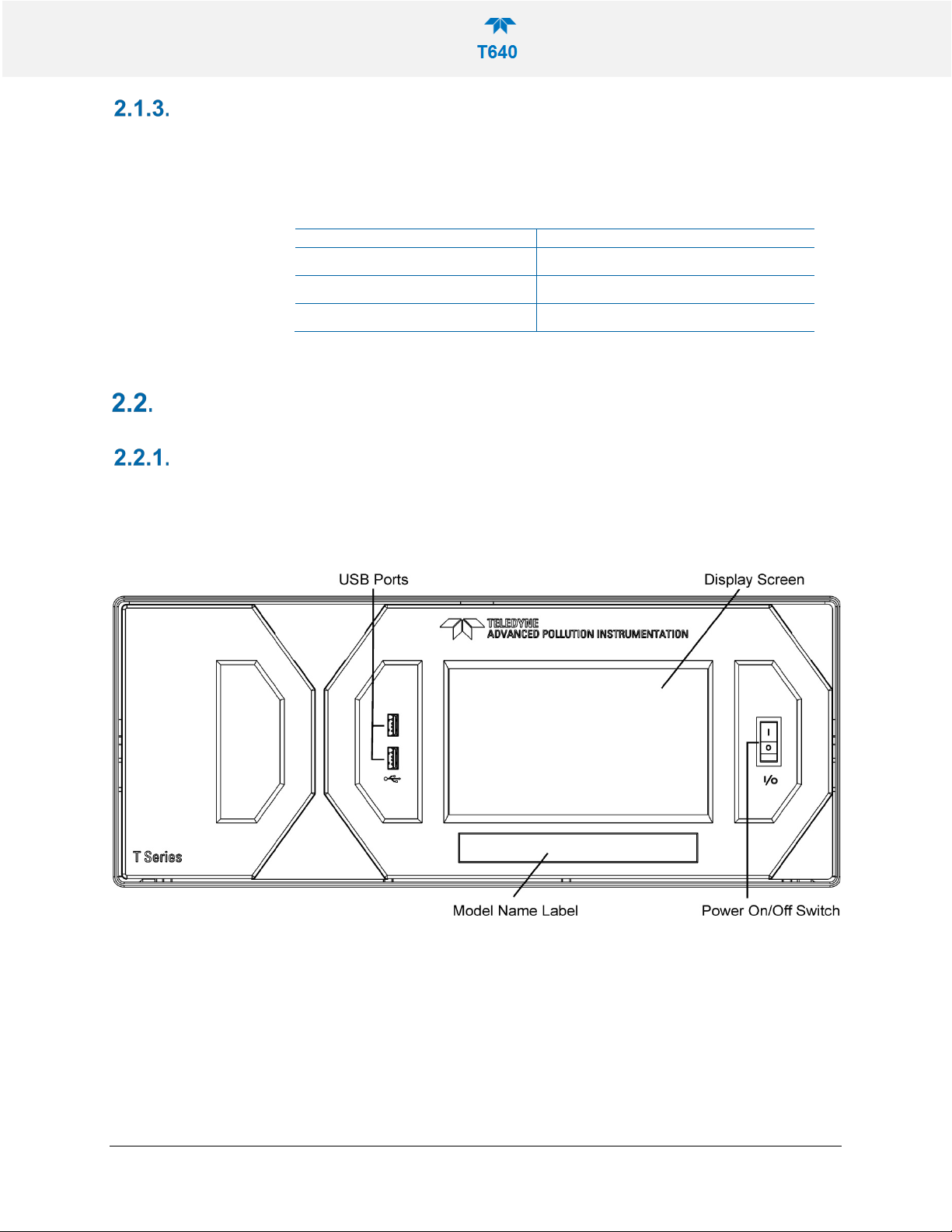
Figure 2-3. Front Panel Layout ................................................................................................................... 16
Figure 2-4. T640 Rear Panel....................................................................................................................... 17
Figure 2-5. T640 with 640x Option Rear Panel........................................................................................... 17
Figure 2-6. T640 Internal Layout, with 640x Option Components .............................................................. 18
08354B DCN7877 Teledyne API T640 PM Mass Monitor vii

Figure 2-7. Top View of Inlet Nozzle ........................................................................................................... 21
Figure 2-8. Inlet Nozzle Adapter for ASC Connectio n ................................................................................ 22
Figure 2-9. Collar for Lower Flange ............................................................................................................ 22
Figure 2-10. Set Screws for ASC ................................................................................................................ 23
Figure 2-11. Collar and ASC Adapter Support............................................................................................ 23
Figure 2-12. Ambient Temperature Probe and ASC Connections (T640 with 640X Option shown) .......... 24
Figure 2-13. T640 Sample Head (5-LPM) and ASC Asse m bl y .................................................................. 25
Figure 2-14. 640X Option Inlet and ASC Assembly .................................................................................... 26
Figure 2-15. Ambient Temperature Sensor Probe In stalled into Radiation Shield ..................................... 26
Figure 2-16. T640 Inlet Tube and Slip Coupler Assem bly .......................................................................... 28
Figure 2-17. 640x Inlet Tube and Slip Coupler Assembly .......................................................................... 29
Figure 2-18. T640 Inlet and Sample Line Assembly ................................................................................... 29
Figure 2-19. 640x Inlet and Sample Line Assembly ................................................................................... 30
Figure 2-20. T640 Rooftop Sample Inlet and Extension Tubing Installation .............................................. 30
Figure 2-21. T640 (left) and 640x (right) Outdoor E nclosures Assembled ................................................. 32
Figure 2-22. T640 Pneumatics .................................................................................................................... 33
Figure 2-23. T640 with 640X Option Pneumatics ....................................................................................... 34
Figure 2-24. Sample Home Screen with Orientation .................................................................................. 35
Figure 2-25. Concentration Graph and Meter Graph .................................................................................. 36
Figure 3-1. Home Configuration thru Home Page Shortcut ........................................................................ 39
Figure 3-2. Dashboard ................................................................................................................................ 39
Figure 3-3. Alerts Log .................................................................................................................................. 40
Figure 3-4. USB Utility Pages ..................................................................................................................... 41
Figure 3-5: Das download Page ............................................................................................................ 42
Figure 3-6: Remote Update Page .......................................................................................................... 43
Figure 3-7: Manual Update Page (and other utilities) ............................................................................ 43
Figure 3-8: Configuration Transfer ........................................................................................................ 44
Figure 3-9: Report Generation Page ..................................................................................................... 45
Figure 3-10. Datalog Configuration, New Log Page ................................................................................... 45
Figure 3-11. Datalog Configuration, Existing Log ....................................................................................... 46
Figure 3-12. Creating a New Data Log ....................................................................................................... 46
Figure 3-13. Datalog Periodic Trigger Configurati on .................................................................................. 47
Figure 3-14. Datalog - Conditional Trigger Configuration ........................................................................... 48
Figure 3-15. DAS Data Utility ...................................................................................................................... 48
Figure 3-16. Events Page ........................................................................................................................... 49
Figure 3-17. Event Configuration ................................................................................................................ 50
Figure 3-18. Existing Event for Viewing or Editing ...................................................................................... 51
Figure 3-19. Dashboard Configuration ........................................................................................................ 51
08354B DCN7877 Teledyne API T640 PM Mass Monitor viii

Figure 3-20. VARS Configuration Page ...................................................................................................... 52
Figure 3-21. Home Configuration thru Setup Menu .................................................................................... 53
Figure 3-22. Touchscreen Calibration Page ............................................................................................... 54
Figure 3-23. Date and Time Configuration Page ........................................................................................ 56
Figure 3-24. Communications Configuration, Net work Settings ................................................................. 59
Figure 4-1. Leak-Check/Flow-Audit Adaptor Kit.......................................................................................... 61
Figure 4-2. Pressure Cal Menu ................................................................................................................... 62
Figure 4-3. Sample Flow Cal Menu ............................................................................................................ 63
Figure 4-4. Bypass Flow Cal Menu ............................................................................................................. 64
Figure 4-5. PMT Adjustment Menu ............................................................................................................. 65
Figure 4-6. Leak Check Menu ..................................................................................................................... 67
Figure 5-1. T640 Inlet (standard) ................................................................................................................ 69
Figure 5-2. 640X Option Disassembly ........................................................................................................ 70
Figure 5-3. Opening the Front Panel .......................................................................................................... 71
Figure 5-4. Internal DFU ............................................................................................................................. 71
Figure 5-5. External DFU, (with 640X Option only) .................................................................................... 72
Figure 5-6. Maintenance: Optics Chamber Windows ................................................................................. 76
Figure 5-7. Maintenance: Final Dusting ...................................................................................................... 76
Figure 6-1. T640 with 640X Option Electronic Block Diagram .................................................................... 83
LIST OF TABLES
Table 1-1. Specifications ............................................................................................................................. 10
Table 2-1. Ventilation Clearance ................................................................................................................. 16
Table 3-1. Setup>Instrument Menu ............................................................................................................ 54
Table 3-2. T640 MODBUS Register ........................................................................................................... 57
Table 3-3. LAN/Ethernet Configuration Prope rt i es ..................................................................................... 59
Table 5-1. Maintenance Schedule .............................................................................................................. 68
Table 5-2. Alerts and Recommendations .................................................................................................... 79
Appendix A: Warranty Repair Questionnaire
Appendix B: Menu Hierarchy
08354B DCN7877 Teledyne API T640 PM Mass Monitor ix

1. INTRODUCTION, SPECIFICATIONS,
PARAMETER
SPECIFICATION
Flow Rate
640X Option
5.0-LPM + 11.67-LPM bypass flow
1 Ethernet: 10/100Base-T (supports MODBUS and HTTP polling pr otocols)
Minimum Resolution (data rate): 10 seconds , user-definable
APPROV ALS, AND COMPLIANCE
The Teledyne API Model T640 with 640X Option is a real-time, continuous
particulate matter (PM) mass monitor that uses scattered light spectrometry for
measurement. The T640 measures 2.5 PM, and the 640X Option measures 2.5, 10,
and coarse PM.
SPECIFICATIONS
Table 1-1 presents the T640 PM Mass Monitor specifications.
Table 1-1. Specifications
Measurement Principle 90° white-light scattering
Light Source Polychromatic LED
Particle Size Resolution 0.18 – 20µm over 256 channels, combined to 64 channels for mass calculation
PM Mass Resolution
Measurement Range
Mass Measurement & Display
Resolution
Precision +/- 0.5 µg/m3 (1-hr average)
0.1 – 10,000 µg/m3
0.1 µg/m3
Lower Detectable Limit < 0.1 µg/m3 (1-hr average)
Mass Concentration Accuracy
T640
640X Option
T640
Flow Accuracy Within +/-1%; (Typically within +/- 0.5%)
AC Power
Instrument
External pump
(640X Option only)
Communication
Data Storage 4 Gb memory allows for >1 year of data storage
Exceeds US EPA Class III PM2.5
Exceeds US EPA US EPA PM10 FEM and Class III PM2.5 & PM10-2.5 FEM
performance requirements for additive and multiplicative bias compar ed to FRM
samplers
5.0-LPM
Rating Typical Power Consumption
110-120 V, 60 Hz 3.0 A
220V-240V, 50/60 Hz 3.0 A
110-120 V, 60 Hz 3.0 A
220V-240V, 50/60 Hz 3.0 A
2 USB device ports
<120 W (at 120 VAC)
<120 W (at 120 VAC)
<360 W (at 120 VAC)
<360 W (at 120 VAC)
08354B DCN7877 Teledyne API T640 PM Mass Monitor 10

PARAMETER
SPECIFICATION
Dimensions
5.0 LPM Model T640 monitor (PM2.5)
EQPM-0516-236
16.7 LPM Model T640 with 640X option monitor (PM2.5)
EQPM-0516-238
16.7 LPM Model T640 with 640X option monitor (PM10-
2.5)
16.7 LPM Model T640 with 640X option monitor (PM10)
EQPM-0516-239
ASC (heater tube)
ASC w/T640 inlet
ASC w/640X Option inlet
Optional external shelter
Weight
Operating Conditions
Operating temperature
Ambient temperature
Ambient Relative Humidity
Sample Humidity Control
Environmental Conditions Installation Category (Over voltage Category) II Pollution Degree 2
1
As defined by the US EPA
H x W x D: 7" x 17" x 14" (178 x 432 x 356 mm)
43” (1092 mm) above the lid
53.5” (1359 mm) above the lid
70” (1778 mm) above the lid
HxWxD: 45” x 25” x 25” (1143 x 635 x 635 mm)
19 lbs (8.6 kg)
w/ T640 ASC + inlet 27 lbs (12.2 kg);
w/ 640X Option ASC + inlet 30 lbs (13.6 kg)
0 - 50°C, non-condensing
-40 - 60°C
0 - 100%
Aerosol Sample Conditioner (ASC) 24VDC 90W (max) heater controlled to
35% RH
For outdoor use only, to ≤ 5000 m altitude
2
At constant temperature and pressure
EPA DESIGNATION
SAFETY
TAPI’s Model T640 PM Mass Monitor and its options are officially designated as
US EPA Federal Equivalent Methods (FEMs) for determining compliance with
particulate matter mass concentration National Ambient Air Quality Standards
(NAAQS). The US EPA designation numbers are as follows:
EQPM-0516-240
The official List of Designated Reference and Equivalent Methods is published in
the U.S. Federal Register: http://federalregister.gov/a/2016-16578
. .
Comply with Code of Federal Regulations, Title 40 (downloadable from the U.S.
Government Publishing Office at http://www/gpo.gov/fdsys/
) and with Quality
Assurance Guidance documents (available on the EPA website,
http://www.epa.gov/ttn/amtic/qalist.html). Give special attention to specific
regulations regarding methods for determining particulate matter.
IEC/EN 61010-1:2010 (3rd Edition), Safety requirements for electrical equipment
for measurement, control, and laboratory use.
CE: 2006/95/EC, Low-Voltage Directive
08354B DCN7877 Teledyne API T640 PM Mass Monitor 11
EMC
IEC/EN 61326-1, Class A Emissions/Industrial Immunity
EN55011 (CISPR 11), Group 1, Class A Emissio ns
FCC 47 CFR Part 15B, Class A Emissions
CE: 2004/108/EC, Electromagnetic Compatibil i t y Directive
2. INST ALLATION AND HAR DWARE SETUP
This section addresses the procedures for unpacking the instrument and inspecting
for damage, presents clearance specifications for proper ventilation, and shows the
instrument layout.
UNPACKING
Verify that there is no apparent external shipping damage. If damage has occurred,
please advise the shipper first, then contact Teledyne API.
Included with your instrument is a printed record of the final performance
characterization performed on your instrument at the factory. This record,
titledT640/640x Mass Monitor Test Data Sheet, is an important quality assuran ce
and calibration record and should be placed in the quality records file for this
instrument.
WARNING – ELECTRICAL SHOCK HAZARD
Never disconnect PCAs, wiring harnesses or electronic
08354B DCN7877 Teledyne API T640 PM Mass Monitor 12
subassemblies while under power.
With no power to the unit, carefully remove the top cover of the instrument and
check for internal shipping damage by carrying out the following steps:
1. Carefully remove the top cover and check for internal shipping damage.
a. Remove the cover screws located on the sides of the instrument.
b. Slide the cover backward until it clears the instrument’s front bezel.
c. Lift the cover straight up.
2. Inspect the interior to ensure all circuit boards an d ot her components are
intact and securely seated.
3. Check the connectors of the various internal wirin g harnesses and pneumatic
hoses to ensure they are firmly and securely seated.
4. Using the paperwork accompanying the instrument, verify that all of the
standard and optional hardware ordered with the unit has been installed.
These are listed on the paperwork accompanyi ng the instrument.

LIST OF STANDARD ITEMS
• Model T640 Instrument with power cord and Test Data Sheet:
• SpanDust
• Aerosol Sample Conditioner (ASC) Tube (~43” long)
• Ambient Temperature Sensor Cable (25’) with ra diation shield and mounting
bracket
• Internal Temperature Sensor Cable (4’) – for performing flow sensor
calibrations from inside shelter without having to di sconnect the normally
installed ambient temperature sensor cable
• CD with operating manuals
TM
bottle with calibration certificate
LIST OF OPTIONAL ACCESSORIES
• Sample head, 5LPM (for T640 base model; PM2.5 FEM)
o Sample Head
o Water collection jar
o ~6” upper inlet tube
• T640 base model extension tube kit
o 8’ long aluminum tube (5/8” OD) with locking collar
o Roof flange with 5/8” cord grip and ¼” cord grip (for am bient temp sen sor
cable)
o Slip coupler (5/8” ID)
• 640x option
o US EPA PM10 inlet, 16.7 LPM
o Outer extension tube (~12” length)
o Inner extension tube (~8” length)
o External vacuum pump pack, 120 or 220V AC with tubing
o Bypass flow splitter / adapter (usually pre-installed onto the ASC from
the factory)
o ¼” black bypass flow tubing
• 640x extension tube kit
o 8’ long aluminum tube (1” OD)
o Step down adapter (1 ¼ ” ID to 1” ID)
o Slip coupler (1” ID)
o Roof flange with 1” cord grip and ¼” cord grip (for ambient t em p sensor
cable)
o Slip coupler (5/8” ID, 1 ¼” OD)
• Support tripod with cord grips for 5/8” or 1” OD tubes
• Leak check / flow audit adapter kit
08354B DCN7877 Teledyne API T640 PM Mass Monitor 13
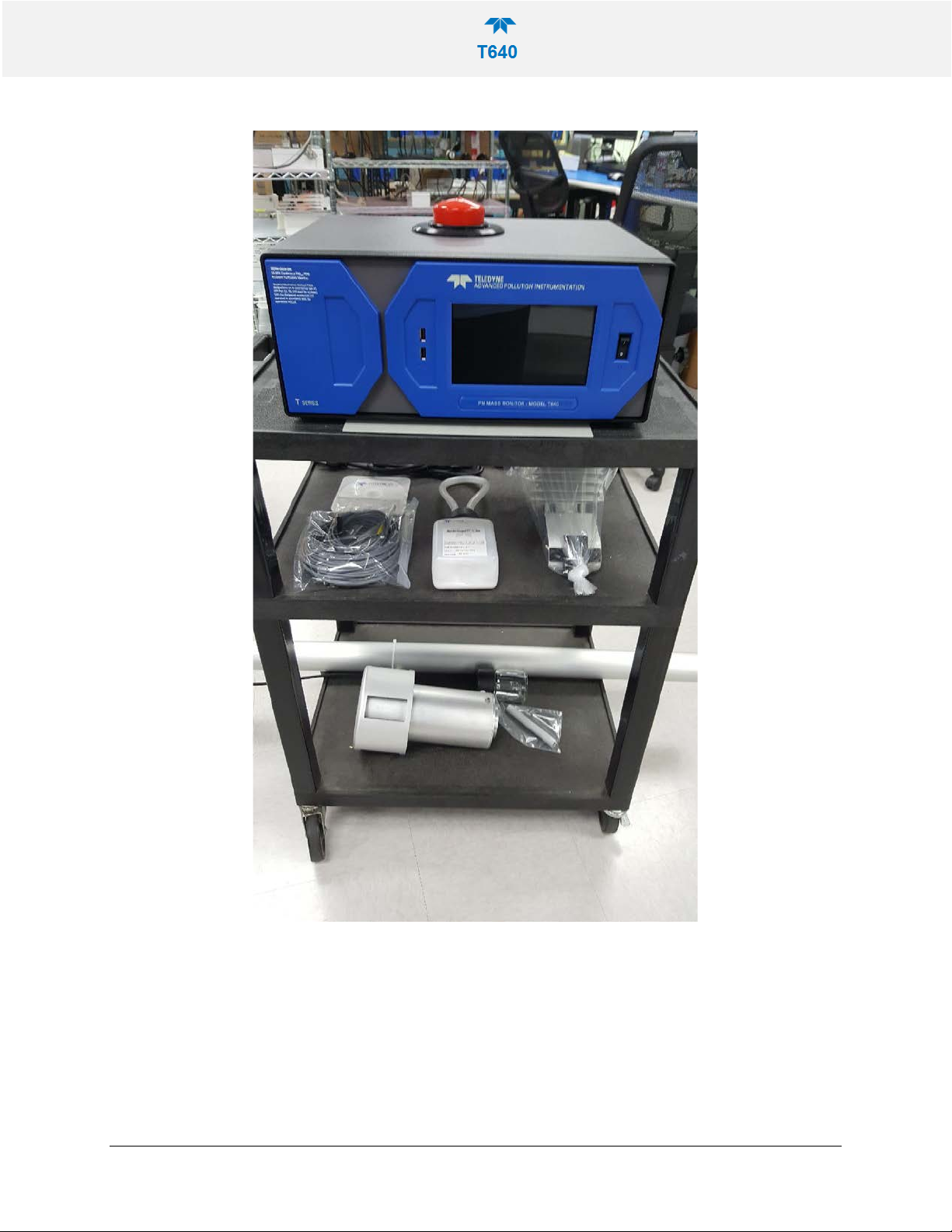
Figure 2-1. T640 Typical Set of Included Hardware
08354B DCN7877 Teledyne API T640 PM Mass Monitor 14
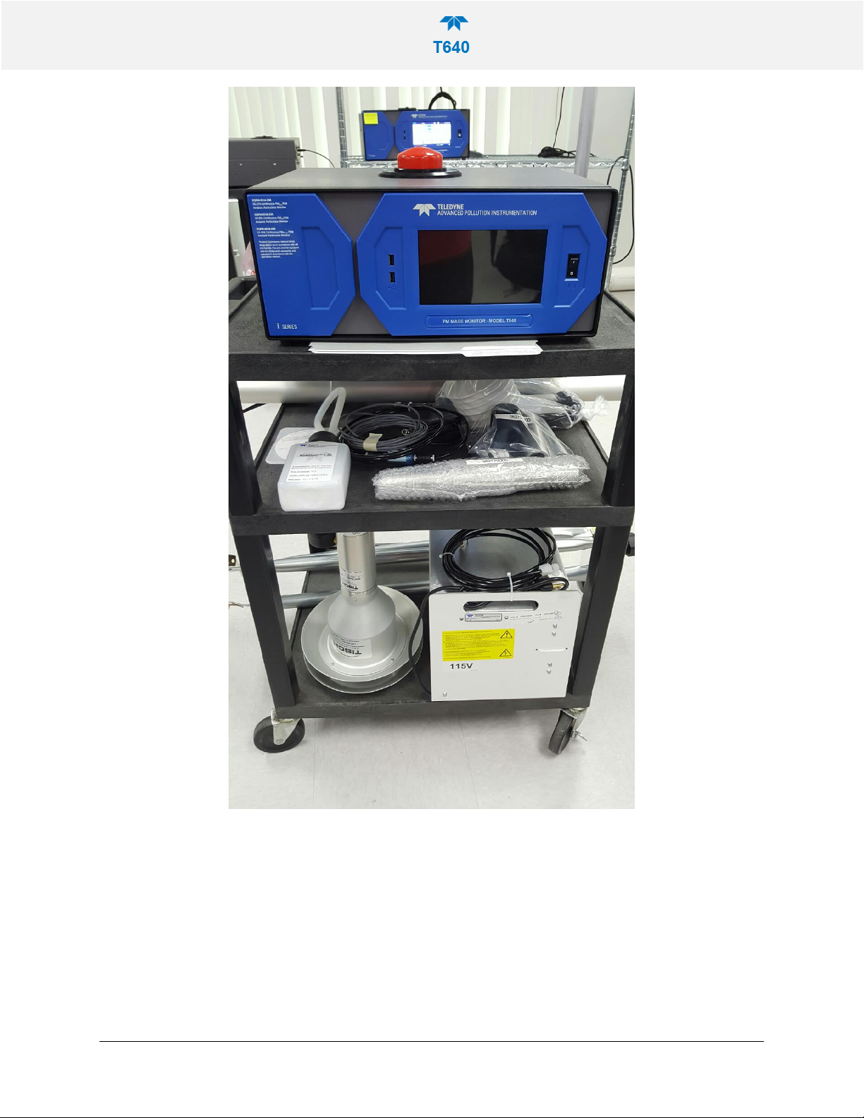
Figure 2-2. 640x Option Typical Set of Included Hardware
08354B DCN7877 Teledyne API T640 PM Mass Monitor 15
VENTILATION CLEARANCE
AREA
MINIMUM REQUIRED CLEARANCE
Whether the Monitor is set up on a be nch or installe d in an instrument rack, be sure
to leave sufficient ventilation clearance.
Table 2-1. Ventilation Clearance
Back of the instrument
Sides of the instrument
Above and below the instrument
INSTRUMENT LAYOUT
FRONT PANEL
Figure 2-3 shows the front panel layout, which has th e display screen, two USB
ports for peripheral device connections: mouse and keyboard as alternatives to the
touchscreen interface, or flash drive for uploads/downloads (devices not inc luded).
10 cm / 4 in
2.5 cm / 1 in
2.5 cm / 1 in
08354B DCN7877 Teledyne API T640 PM Mass Monitor 16
Figure 2-3. Front Panel Layout
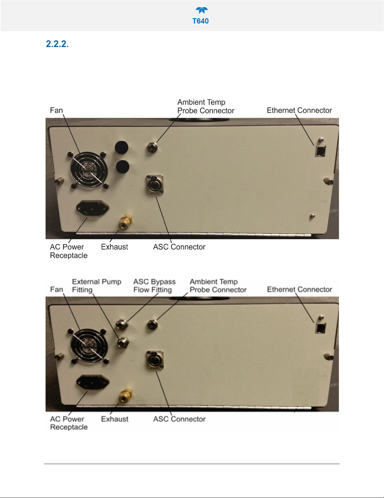
REAR PANEL
The rear panel shows fittings and connectors for the monitor’s functions as well as
connectors for communication.
Figure 2-4. T640 Rear Panel
Figure 2-5. T640 with 640x Option Rear Panel
08354B DCN7877 Teledyne API T640 PM Mass Monitor 17
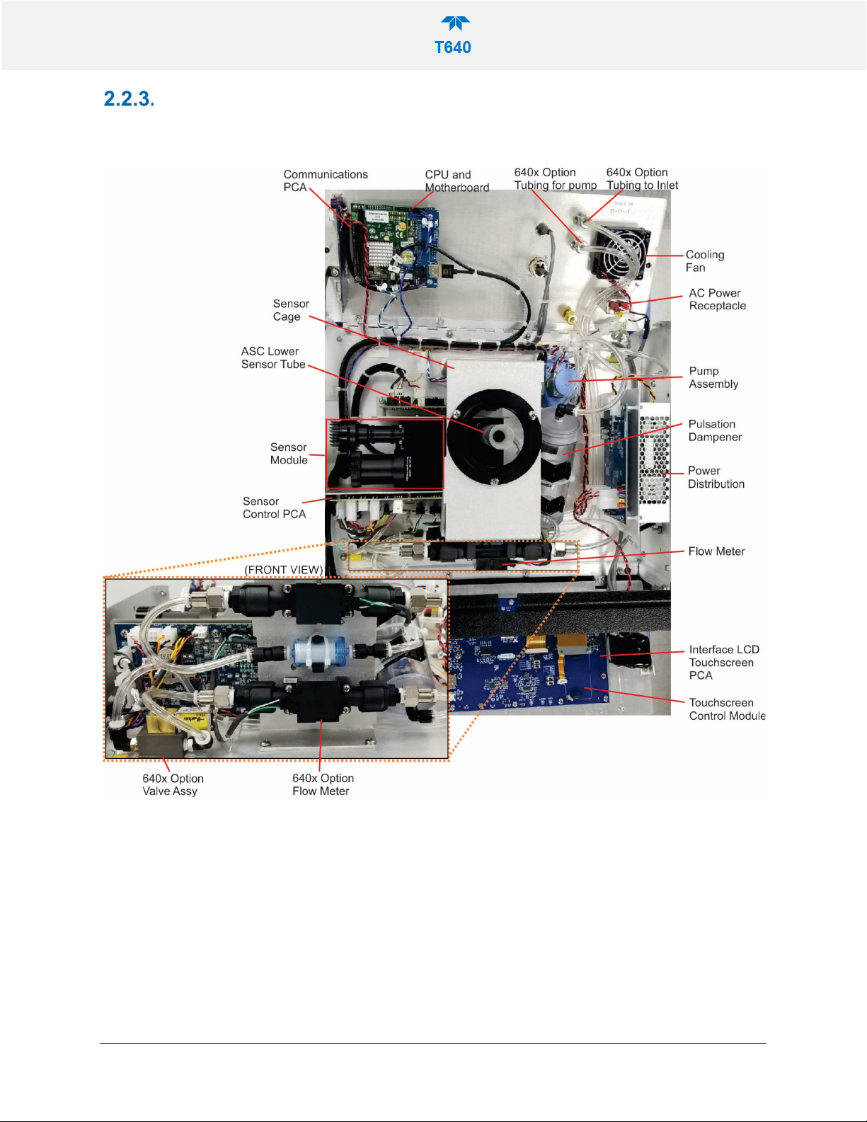
INTERNAL LAYOUT
Below shows the main components and assemblies of the monitor.
Figure 2-6. T640 Internal Layout, with 640x Option Components
08354B DCN7877 Teledyne API T640 PM Mass Monitor 18
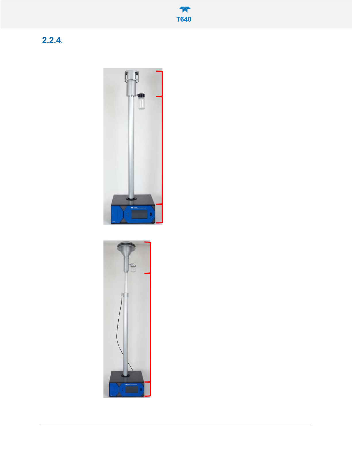
HEIGHT DIMENSIONS
T640 Chassis = 7
-in tall
For indoor shelter installation, the
height is 43-in + 3-in for the upper
sampling tube (which goes into the
inlet in this picture) that couples to
the extens ion tube, making
46-in
total above the ins trument lid.
T640 ASC = 43-in tall above the
chassis lid.
T640 Inlet = 10.5-in tall
PM10 Inlet = 15.5-in tall
T640 Chassis = 7-in tall
For indoor shelter installation, the
height is 43-in + 10-in for the PM10
extension tube + 6-i n for the slip
coupler fittings (not shown here)
that couple to the extens ion tube,
making 59-in total above the
instrument lid. Allow extra space
above for sliding tubing on/off the
fittings.
T640 ASC = 43-in tall above the
chassis lid.
T640:
640x:
08354B DCN7877 Teledyne API T640 PM Mass Monitor 19
CONNECTIONS AND STARTUP
Do not operate with cover off.
the instrument’s model/specs label before plugging it into line power.
Note
This section presents the various connections for setup and preparing the
instrument for operation (Section 2.6).
WARNING: ELECTRICAL SHOCK HAZARD
• High Voltages are present inside the instrument.
• Ensure that the power cord being used is capable of carrying the
power rating of the instrument (see rear panel label).
• Power connection must have functioning ground connection.
• Do not defeat the ground wire on power plug.
• Turn off instrument power before disconnecting or connecting
electrical subassemblies.
•
CAUTION – AVOID DAMAGE TO THE INSTRUMENT
Do not operate under conditions outside the environmental
specifications. Operating this instrument under different
environmental conditions, such as corrosive or explosive
environments, electric or electromagnetic fields, areas of ionizing
radiation, or areas conducive to shock or vibration, could damage or
destroy the instrument.
CAUTION – AVOID DAMAGE TO THE INSTRUMENT
Ensure that the AC power voltage matches the voltage indicated on
To maintain compliance with EMC standards, any cable length must
be no greater than 3 meters for all communication connections.
POWER CONNECTION
Adhering to the warning messages previously introduced (Section 2.3), insert the
power cord between the instrument’s AC power connector and a properly rated
power outlet.
08354B DCN7877 Teledyne API T640 PM Mass Monitor 20
COMMUNICATIONS INTERFACE CONNECTIONS
IMPORTANT
instrument’s performance.
For network or Internet communication with the instrument, connect an Ethernet
cable from the analyzer’s rear panel Ethernet i nterface connector to an Ethernet
port. Although the analyzer is shipped with DHCP enabled by default, it should be
manually assigned a static IP address. See Section 3.2.13. The USB ports are f or
other utilities described later in this manual.
AEROSOL SAMPLE CONDITIONER (ASC) CONNECTIONS AND
INSTALLATION
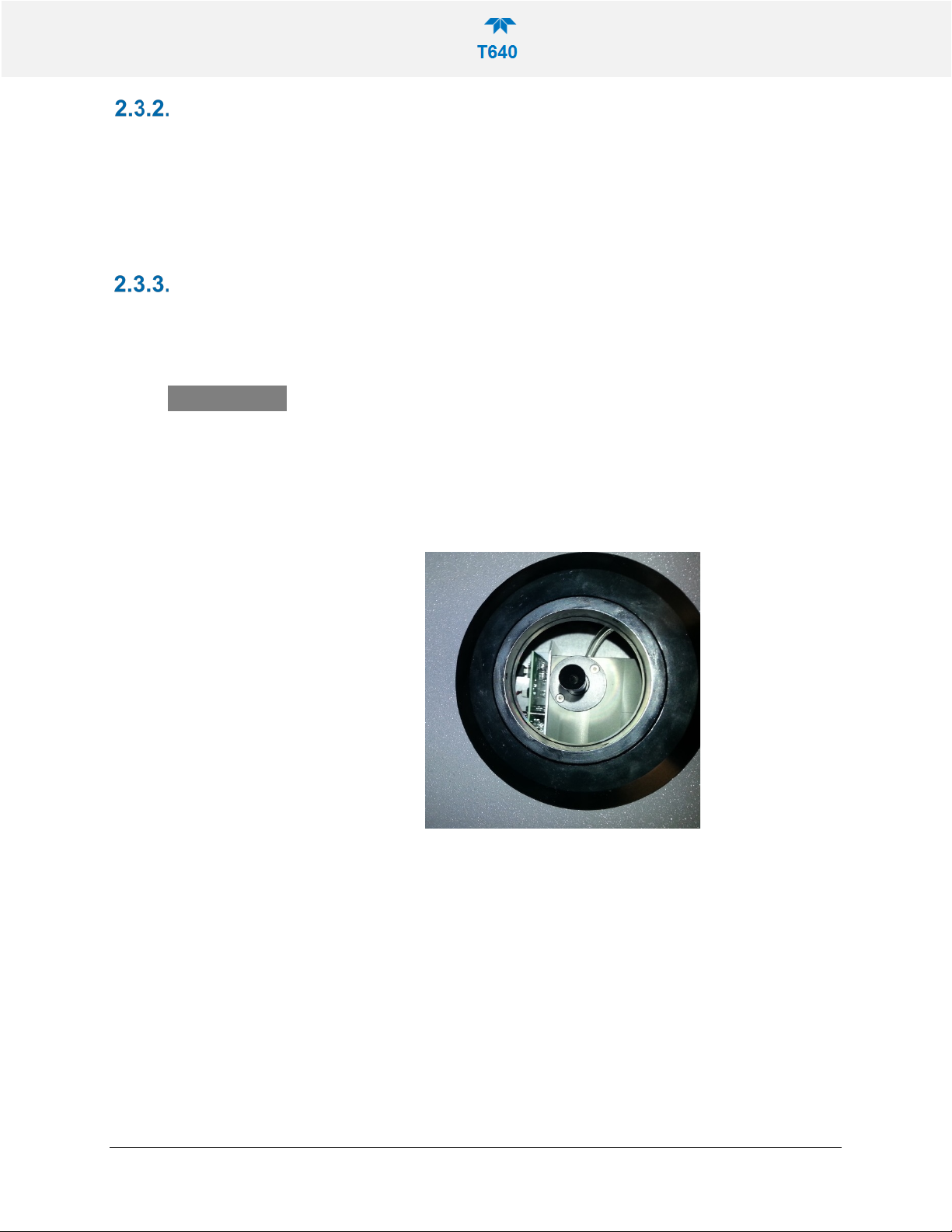
The ASC requires an inlet nozzle adapter fo r in stallation.
IMPACT ON READINGS OR DATA
The black inlet nozzle to the optical sensor is specific to the
instrument and is not interchangeable with other T640
instruments. Use caution when handling and contact TAPI Tech
Support if this piece is ever damaged as it could affect the
08354B DCN7877 Teledyne API T640 PM Mass Monitor 21
Figure 2-7. Top View of Inlet Nozzle
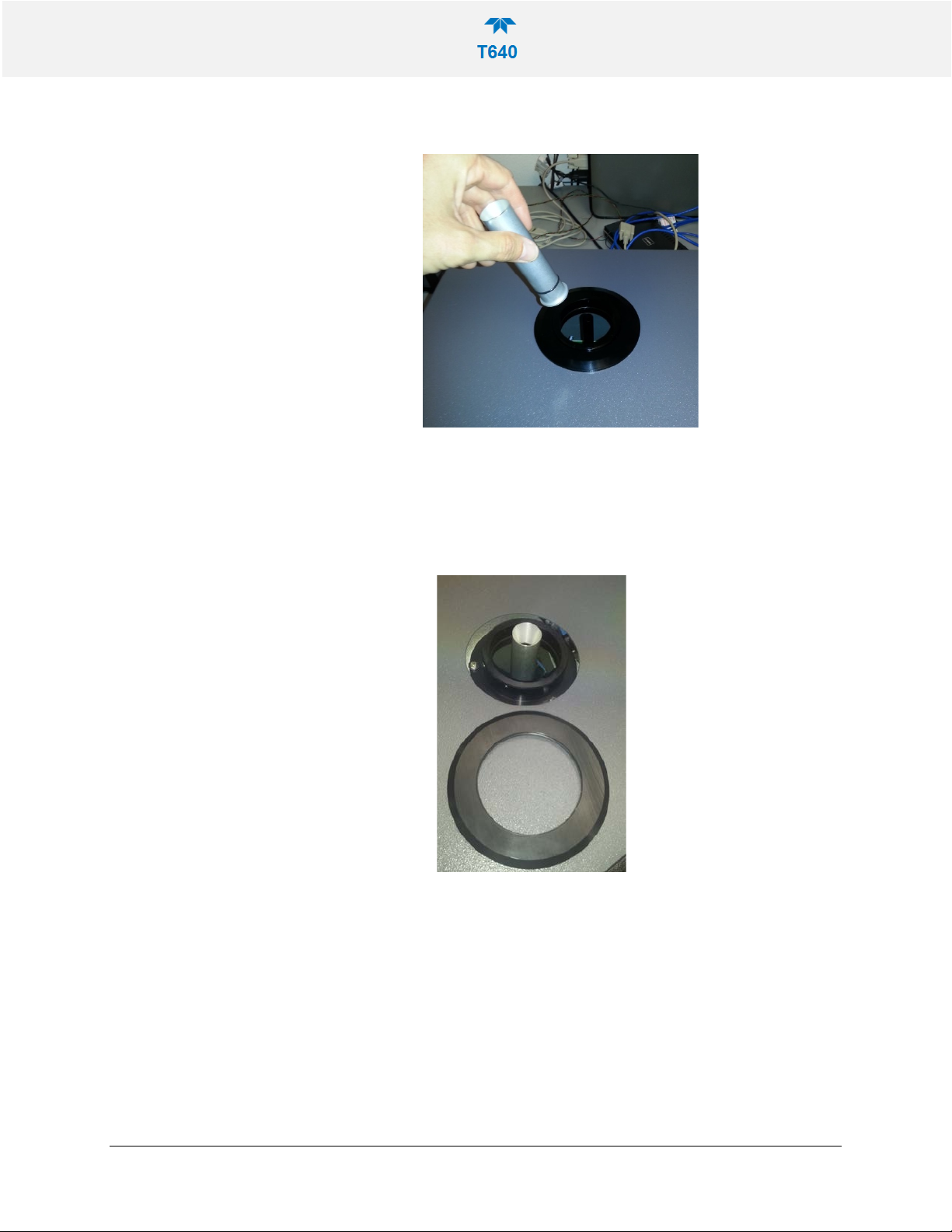
1. Slide the aluminum adapter over the black inlet nozzle, ensuring its base is
flush with the top of the optical sensor.
Figure 2-8. Inlet Nozzle Adapter for ASC Connection
2. Remove collar from lower flange of the instrument as shown:
Figure 2-9. Collar for Lower Flange
08354B DCN7877 Teledyne API T640 PM Mass Monitor 22
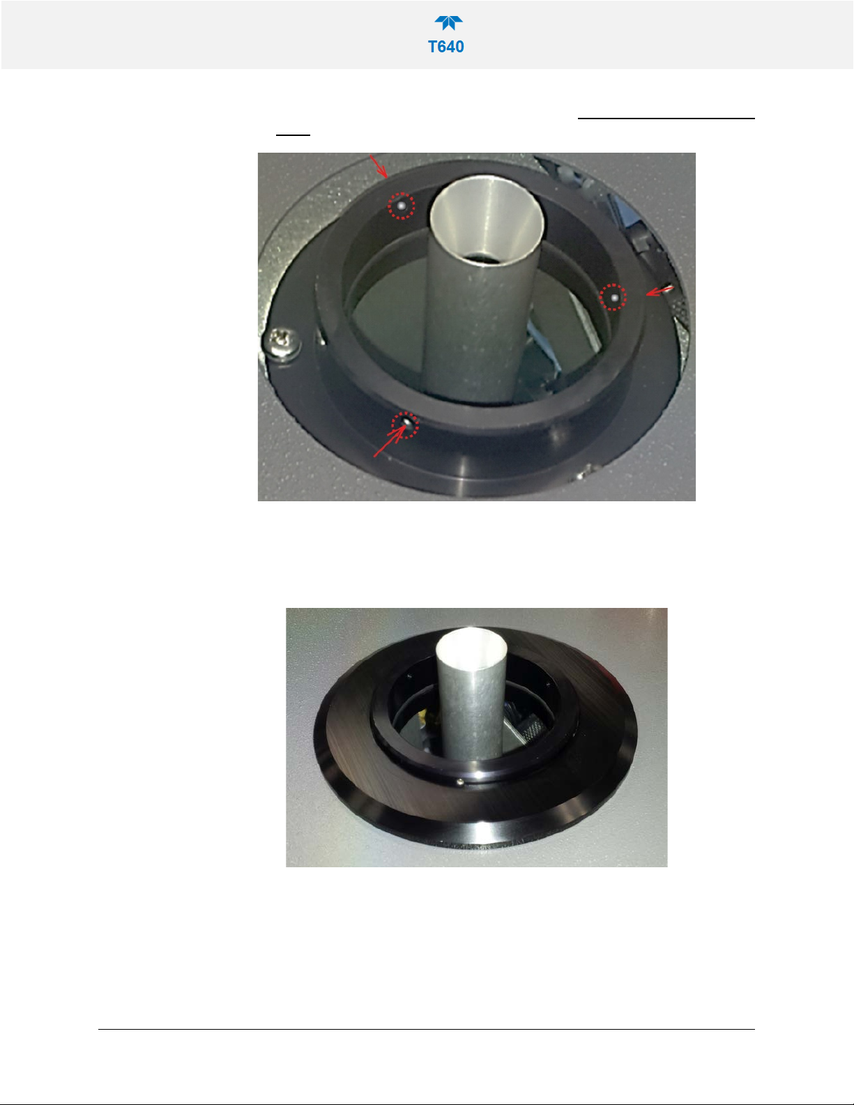
3. Identify the three openings on the lower flange ASC support and insert set
screws on them. Use a 1/16” Hex/Allen Wrench. Do not tighten them at this
point.
Figure 2-10. Set Screws for ASC
4. Replace collar over lower flange/ASC support:
Figure 2-11. Collar and ASC Adapter Support
5. Carefully place ASC over sample inlet making sure it properly seated by
applying sufficient pressure to slide past the internal o-rings at the base of the
inlet nozzle adapter. Be sure the ASC is oriented squarely, by using a plumb
bob or level:
08354B DCN7877 Teledyne API T640 PM Mass Monitor 23
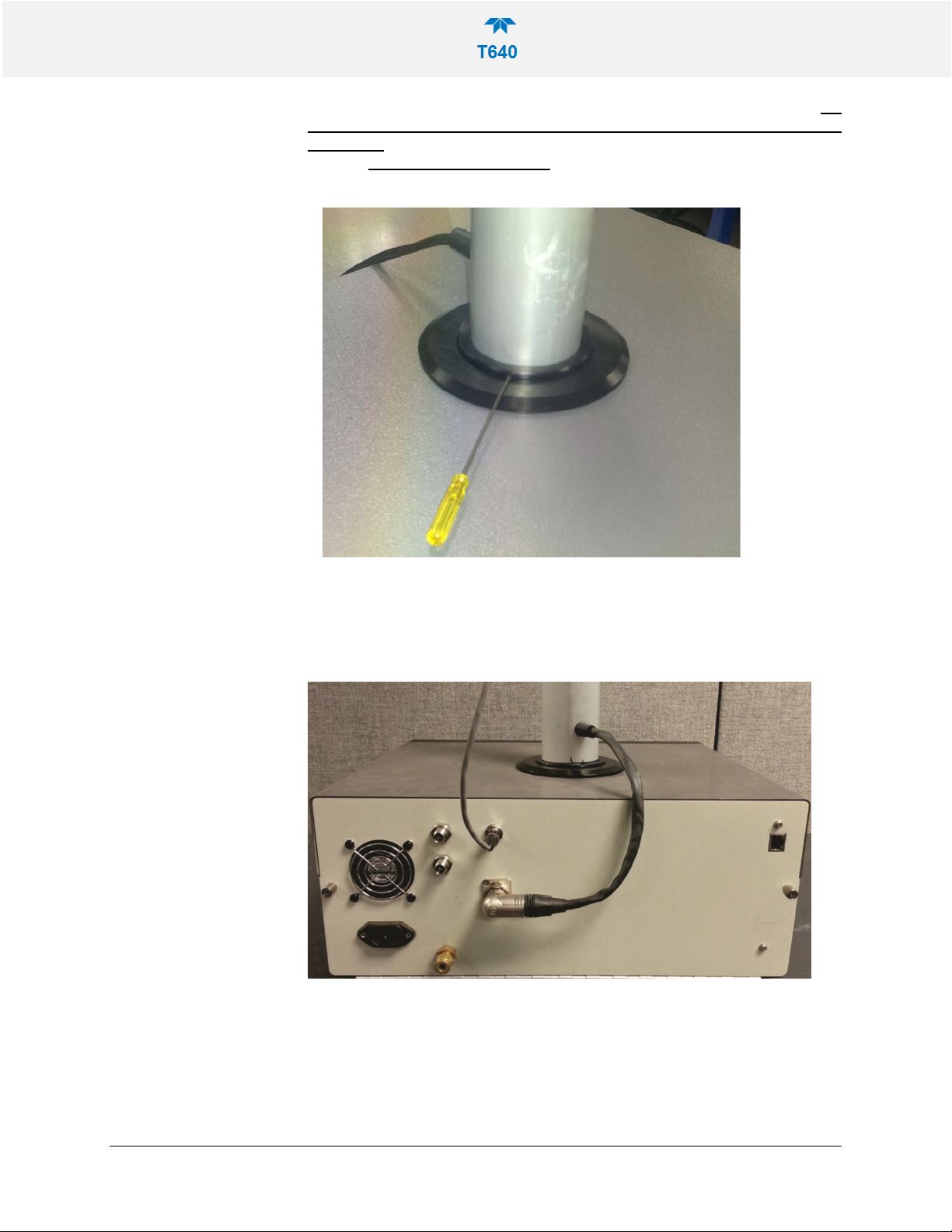
6. Once the ASC is leveled, set screws should be hand tightened until snug. Do
not over-tighten; the screws should be relatively easy to loosen when
necessary. Press slightly on instrument top cover to allow more clearance if
needed. Do not use thread locker.
7. Connect the ASC power and communications cable to the rear panel of the
T640 labeled ASC Connector (or IADS Connector in some cases).
8. Locate the 25’ temperature sensor cable (15’ in some cases). Pl ug the ambient
temperature probe connector into its respective rear panel electrical port.
Figure 2-12. Ambient Temperature Probe and ASC Connections (T640 with
640X Option shown)
08354B DCN7877 Teledyne API T640 PM Mass Monitor 24
INLET INSTALLATION
1. To complete the installation now will depend on whether t he instrument is being
installed in an Outdoor Enclosure or Walk-in Shelter. If performing testing in a
laboratory, you can proceed with attaching the inlet.
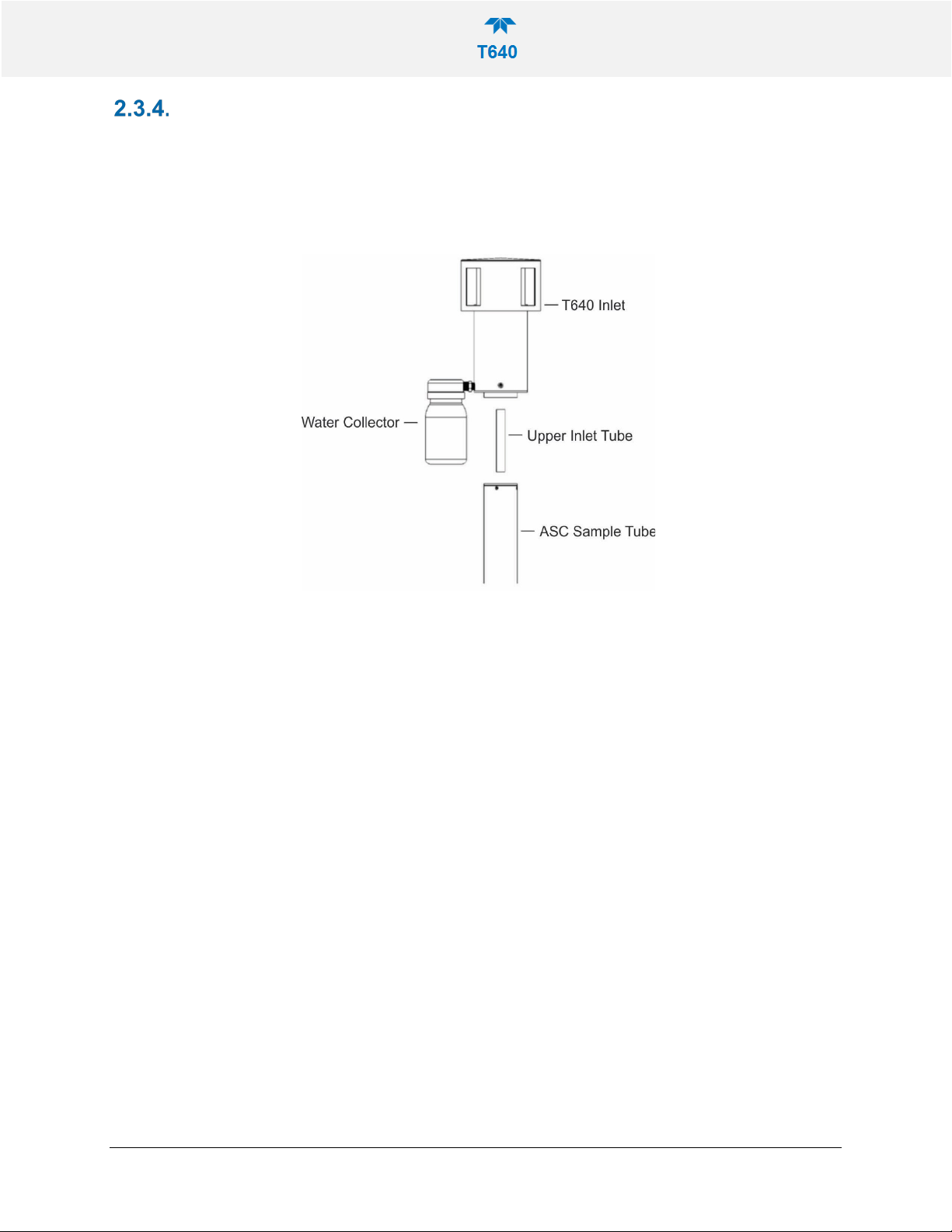
2. For the T640, assemble the inlet and the ASC as depicted below ( Figure 2-13.
T640 Sample Head (5-LPM) and ASC Assembly).
Figure 2-13. T640 Sample Head (5-LPM) and ASC Assembly
08354B DCN7877 Teledyne API T640 PM Mass Monitor 25
 Loading...