


1
Programming Guide
T3DSO1000 and T3DSO2000 Digital
Oscilloscopes Programming Guide
Manual Version 1.2

Digital Oscilloscope Series
2
Version Declaration
This chapter indicates the modifications of commands in the most recent
release of the programming guide version.
Introduction
Manual version 1.2 describes all the currently available commands. Some
of the commands vary between the oscilloscope series, and these will be
annotated in the description of command.
The following are the main revisions:
w Delete the Table of Commands & Queries, and all the instructions are
classified according to the functional modules.
w Removed incorrect instructions, added instructions for GEN and DIGITAL
modules.
w Add two new communication features: Telnet and Socket, visible in
“Programming Overview-Remote Control”.
w Detailed programming instances for instructions (WF?/SCDP) to make
it easier to understand.
w Support obtaining waveform data of Digital channel and Math.

Digital Oscilloscope Series
3
Content
Programming Overview ....................................... .......................................... .... 6
Establishing Communications ....................................... ................................. 6
Install NI-VISA ....................................... ......................................... .......... 6
Connect the Instrument.................. ......................................... .................. 10
Remote Control ........................................... ......................................... ........ 11
User-defined Programming......................................... .............................. 11
Send SCPI Commands via NI-MAX ....................................... ................. 11
Using SCPI with Telnet.................................. .......................................... 11
Using SCPI with Sockets............................................... ........................... 13
Introduction to the SCPI Language ....................................... ........................... 14
About Commands & Queries........................... ............................................. 14
Description ........................................... ........................................................ 14
Usage................................................................................... ......................... 14
Command Notation....................................................................................... 15
Commands & Queries ...................................................................................... 17
COMMON (*) Commands ................................................. .......................... 18
COMM_HEADER Commands ....................................... ............................. 22
ACQUIRE Commands ....................................... ......................................... . 24
AUTOSET Commands........................................ ......................................... 38
CHANNEL Commands .............................................. .................................. 40
CURSOR Commands................................... ......................................... ....... 50
DIGITAL Commands......... .......................................................................... 58
DISPLAY Commands ................................ ........................................ .......... 68
HISTORY Commands................... ........................................ ....................... 74

Digital Oscilloscope Series
4
MATH Commands......................................... ......................................... ......79
MEASURE Commands........................ .........................................................96
PASS/FAIL Commands ............................... ........................................ .......110
PRINT Commands................................... ........................................ ...........122
RECALL Commands ..................................... ......................................... ....124
REFERENCE Commands............. ........................................ ...................... 128
SAVE Commands ...................................................................................... .138
STATUS Commands.............................. .....................................................145
SYSTEM Commands........ ......................................... ................................. 148
TIMEBASE Commands.............. ................................................................ 153
TRIGGER Commands ....................................... ......................................... 161
WAVEFORM Commands ....................................... ................................... 178
WGEN Commands.............................. ........................................ ................19 2
Programming Examples ................................................................................. 199
VISA Examples................................... ......................................... ...............200
VC++ Example........................................................................................ 200
VB Example....... ............................................ ......................................... 207
MATLAB Example........... ......................................................................213
LabVIEW Example .................................... .............................................215
C# Example............ ................................................................................. 218
Examples of Using Sockets......................................................................... 221
Python Example ......................................................................................221
C Example............. ..................................................................................224
Common Command Examples............................................................ ........226
Read waveform data (WF) Example .......................................................226

Digital Oscilloscope Series
5
Screen Dump (SCDP) Example................... ........................................... 228
Index................... ......................................... ....................................... ............ 229

Digital Oscilloscope Series
6
Programming Overview
This chapter introduces how to build communication between the instrument and
the PC. It also introduces how to configure a system for remote instrument control.
By using USB and LAN interfaces, in combination with NI-VISA and
programming languages, users can remotely control the instruments. Through LAN
interface, VXI-11, Sockets and Telnet protocols can be used to communicate with
the instruments.
Establishing Communications
Install NI-VISA
Before programming, you need to install the National Instruments NI-VISA
library, which you can download from the National Instruments web site.
Currently, NI-VISA is packaged in two versions: a full version and a Run-Time
Engine version. The full version includes the NI device drivers and a tool named
NI MAX which is a user interface to control and test remotely connected
devices. The Run-Time Engine is recommended, as it is a much smaller
download than the full version and includes the necessary tools for basic
communication to instruments.
For example, you can get the NI-VISA 5.4 full version from:
http://www.ni.com/download/ni-visa-5.4/4230/en/.
You also can download NI-VISA Run-Time Engine 5.4 to your PC and install it
as the default selection. Its installation process is similar with the full version.
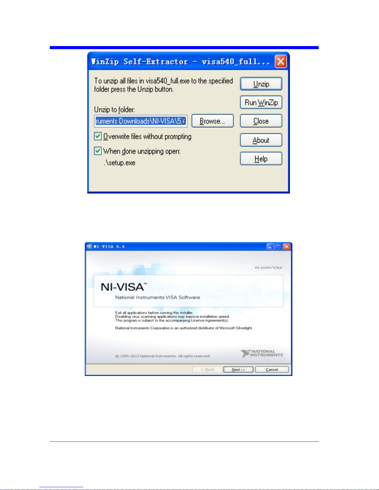
After you downloaded the file, follow these steps to install NI-VISA (The full
version of NI-VISA 5.4 is used in this example. Newer versions are likely, and
should be compatible with Teledyne Test Tools instrumentation. Download the
latest version available for the operating system being used by the controlling
computer):
a. Double click the visa540_full.exe, dialog shown as below:
Digital Oscilloscope Series
7
b. Click Unzip, the installation process will automatically launch after unzipping
files. If your computer needs to install .NET Framework 4, it may auto start.
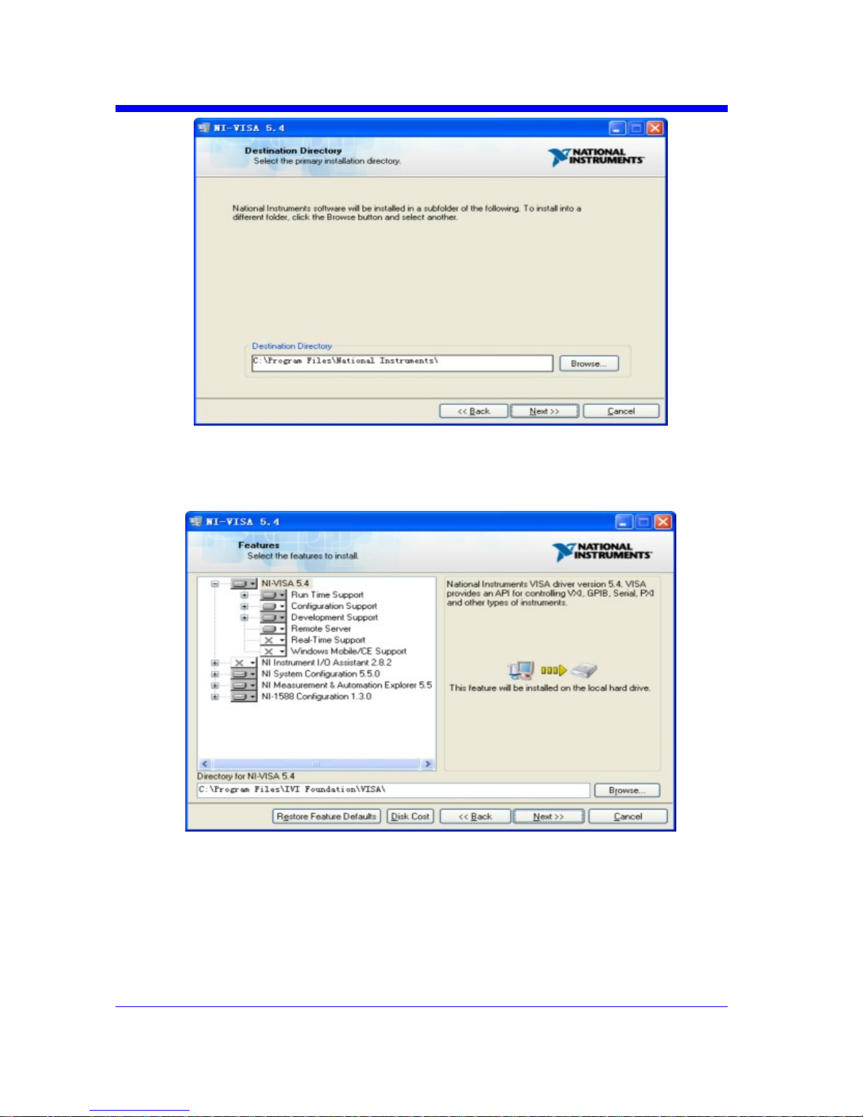
c. The NI-VISA installing dialog is shown above. Click Next to start the
installation process.
Digital Oscilloscope Series
8
d. Set the install path, default path is “C:\Program Files\National Instruments\”,
you can change it. Click Next, dialog shown as above.
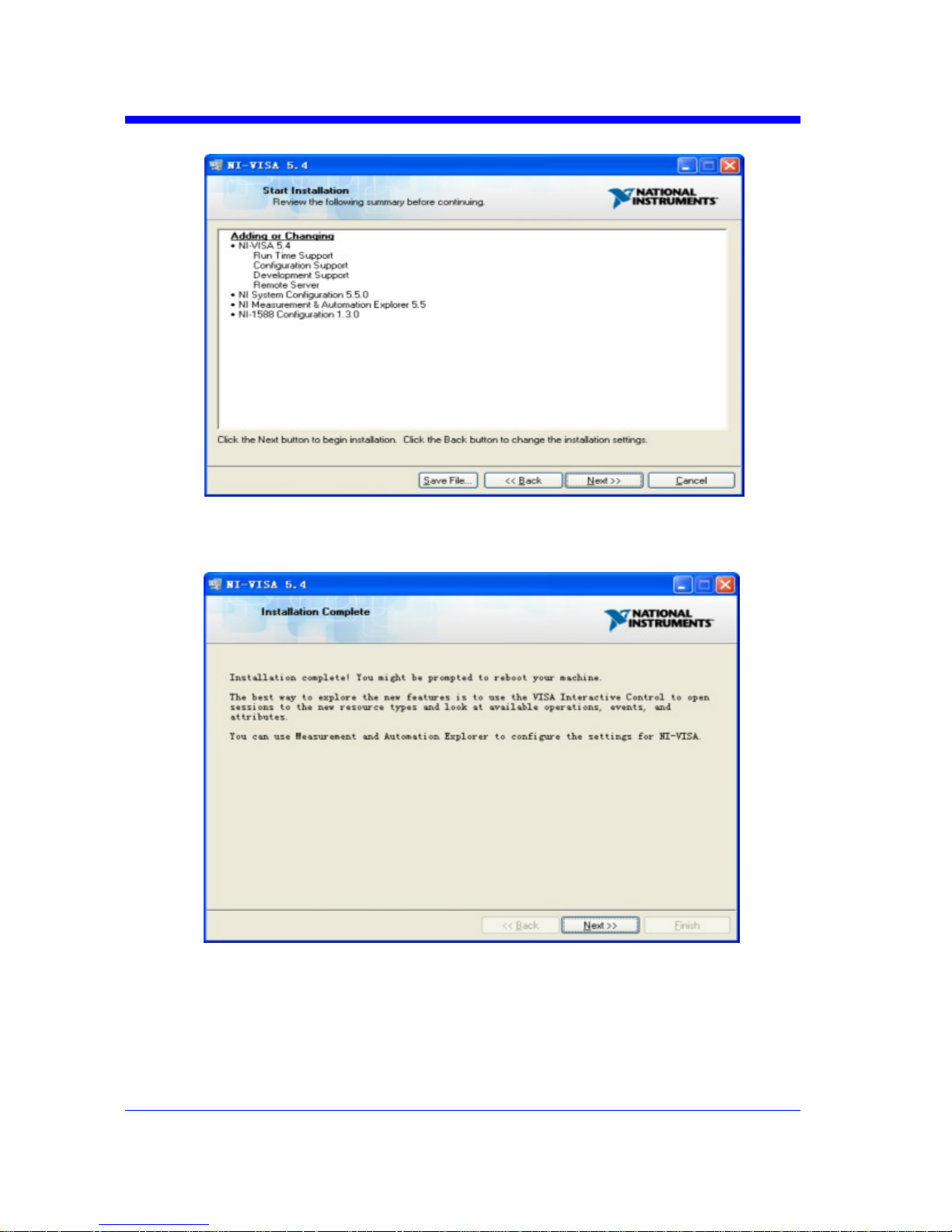
e. Click Next twice, in the License Agreement dialog, select the “I accept the
above 2 License Agreement(s).”,and click Next, dialog shown as below:
Digital Oscilloscope Series
9
f. Click Next to begin installation.
g. Now the installation is complete. Reboot your PC.
Digital Oscilloscope Series
10
Connect the Instrument
Depending on the specific model, your oscilloscope may be able to communicate
with a PC through the USB or LAN interface.
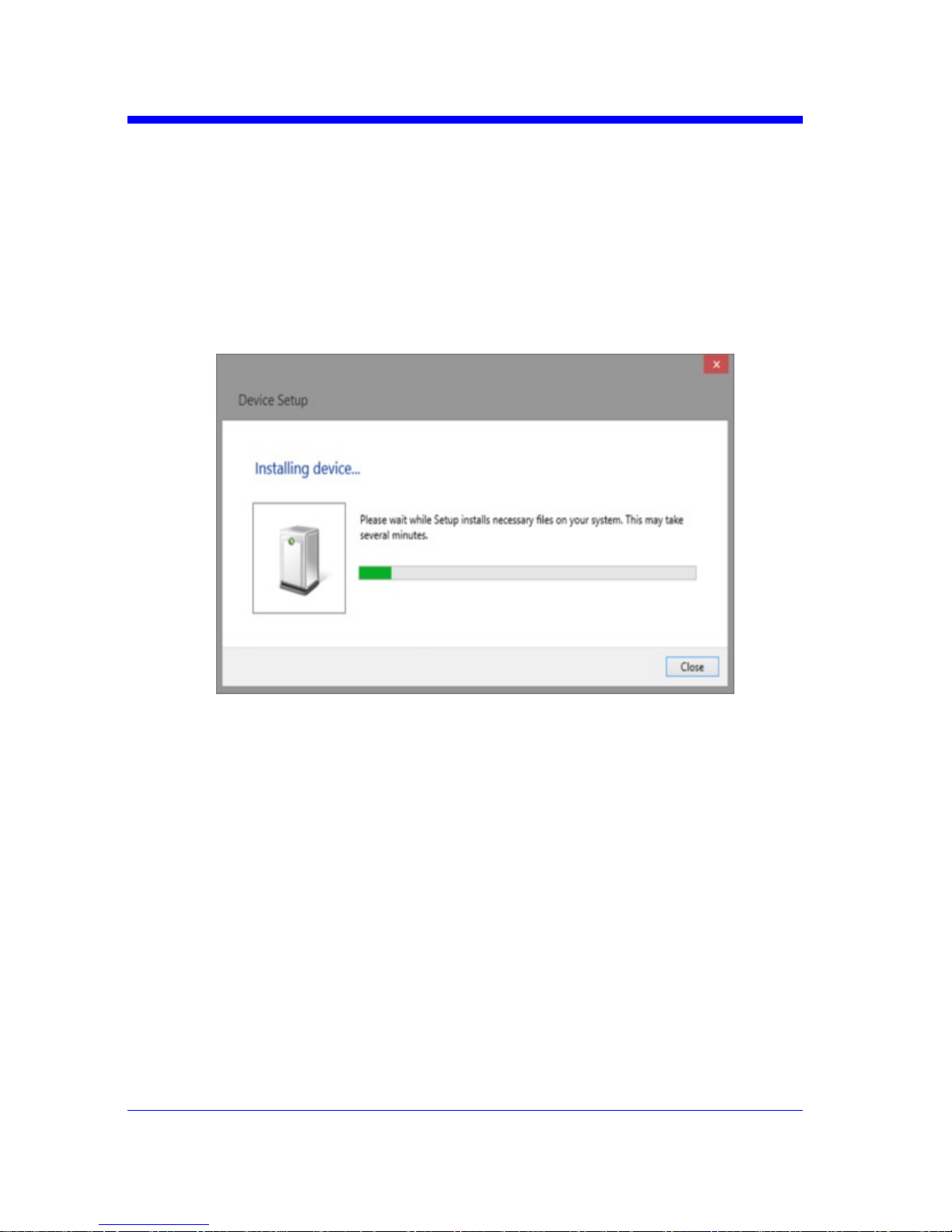
Connect the instrument and the USB Host interface of the PC using a USB cable.
Assuming your PC is already turned on, turn on your oscilloscope, and then the
PC will display the “Device Setup” screen as it automatically installs the device
driver as shown below.
Wait for the installation to complete and then proceed to the next step.

Digital Oscilloscope Series
11
Remote Control
User-defined Programming
Users can use SCPI commands via a computer to program and control the digital
oscilloscope. For details, refer to the introductions in "Programming Examples".
Send SCPI Commands via NI-MAX
NI-Measurement and Automation eXplorer (NI-MAX) is a program created and
maintained by National Instruments. It provides a basic remote control interface
for VXI, LAN, USB, GPIB, and Serial communications. It is a utility that enables
you to send commands one-at-a-time and also retrieve data from connected devices.
It is a great tool for troubleshooting and testing command sequences. The
oscilloscopes can be controlled remotely by sending SCPI commands via NI-MAX.
Using SCPI with Telnet
Telnet provides a means of communicating with the oscilloscopes over a LAN
connection. The Telnet protocol sends SCPI commands to the oscilloscopes from
a PC and is similar to communicating with the oscilloscopes over USB. It sends
and receives information interactively: one command at a time. Windows operating
systems use a command prompt style interface for the Telnet client. The steps are
as follows:
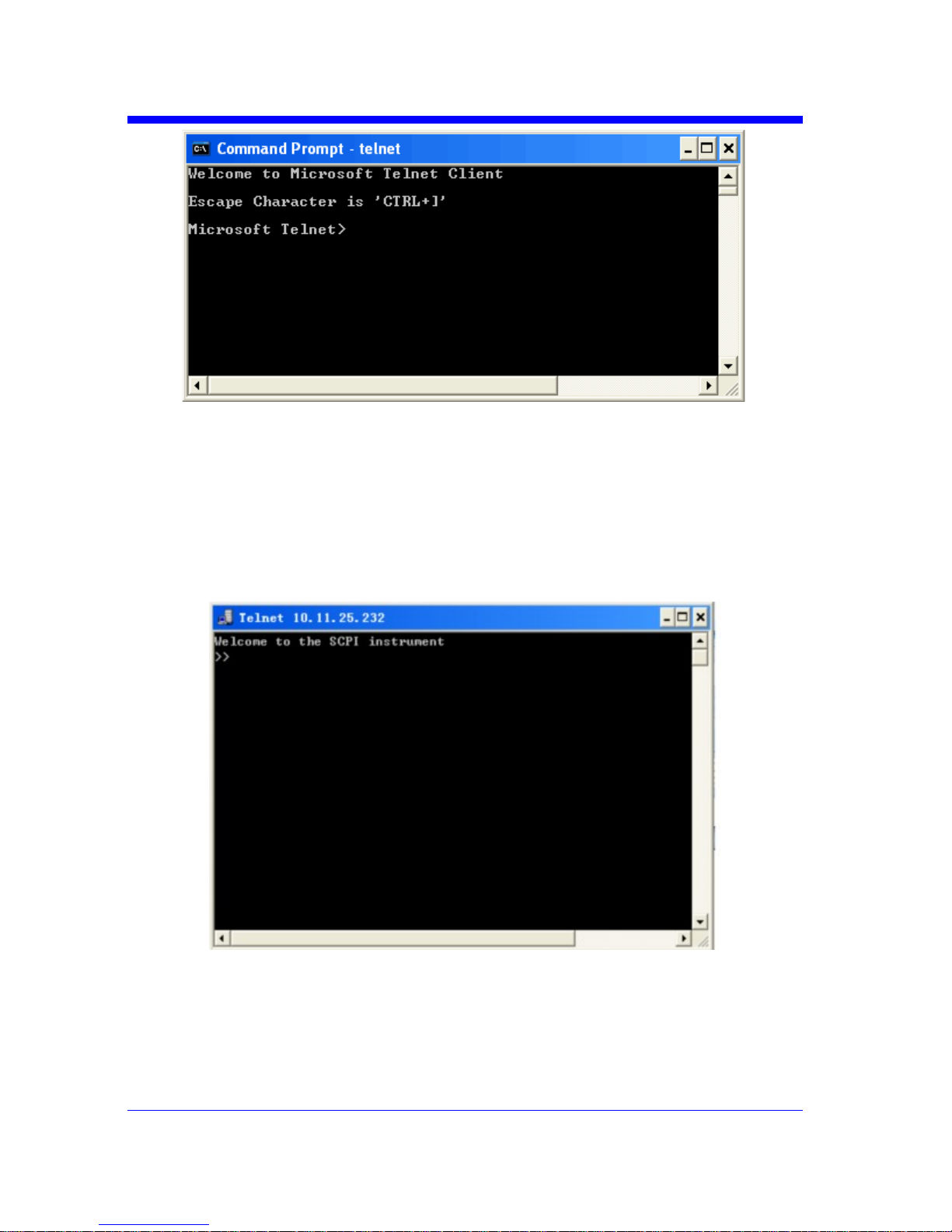
1. On your PC, click Start > All Programs > Accessories > Command Prompt.
2. At the command prompt, type in telnet.
3. Press the Enter key. The Telnet display screen will be displayed.
Digital Oscilloscope Series
12
4. At the Telnet command line, type:
open XXX.XXX.XXX.XXX 5024
Where XXX.XXX.XXX.XXX is the instrument‘s IP address and 5024 is the port.
You should see a response similar to the following:
5. At the SCPI> prompt, input the SCPI commands such as *IDN? to return the
company name, model number, serial number, and firmware version number.

Digital Oscilloscope Series
13
6. To exit the SCPI> session, press the Ctrl+] keys simultaneously.
7. Type quit at the prompt or close the Telnet window to close the
connection to the instrument and exit Telnet.
Using SCPI with Sockets
Socket API can be used to control the T3DSO series via LAN without
installing any other libraries. This can reduce the complexity of
programming.
SOCKET ADDRESS IP address + port number
IP ADDRESS T3DSO IP address
PORT NUMBER 5024
Please see section "Examples of Using Sockets" for the details.

Digital Oscilloscope Series
14
Introduction to the SCPI Language
About Commands & Queries
This section lists and describes the remote control commands and queries
recognized by the instrument. All commands and queries can be executed
in either local or remote state.
The description for each command or query, with syntax and other
information, begins on a new page. The name (header) is given in both
long and short form at the top of the page, and the subject is indicated as
a command or query or both.
The commands are given in long format for the “COMMAND SYNTAX“
and “QUERY SYNTAX“ sections and they are used in a short form for the
“EXAMPLE” .
Queries perform actions such as obtaining information, and are recognized
by the question mark (?) following the header.
Description
In the description, a brief explanation of the function performed is given.
This is followed by a presentation of the formal syntax, with the header
given in upper case characters and the short form derived from it. Where
applicable, the syntax of the query is given with the format of its response.
Usage
The commands and queries listed here can be used for the T3DSO1000
and T3DSO2000 Digital Oscilloscope Series.

Digital Oscilloscope Series
15
Command Notation
The following notations are used in the commands:
< > Angular brackets enclose words that are used as placeholders, of which there
are two types: the header path and the data parameter of a command.
:= A colon followed by an equals sign separates a placeholder from the
description of the type and range of values that may be used in a
command instead of the placeholder.
{ } Braces enclose a list of choices, one of which one must be made.
[ ] Square brackets enclose optional items.
… An ellipsis indicates that the items both to its left and right may be repeated
for a number of times.
As an example, consider the syntax notation for the command to set the vertical
input sensitivity:
<channel>:VOLT_DIV <v_gain>
<channel>:={C1,C2,C3,C4}
<v_gain>:= 2 mV to 10 V
The first line shows the formal appearance of the command, with <channel>
denoting the placeholder for the header path and <v_gain> the placeholder for
the data parameter specifying the desired vertical gain value. The second line
indicates that one of four channels must be chosen for the header path. And the
third explains that the actual vertical gain can be set to any value between 2 mV
and 10 V.

Digital Oscilloscope Series
16

Digital Oscilloscope Series
17
Commands & Queries
This chapter introduces each command subsystem of the Teledyne Test Tools
Digital Oscilloscope Series command set. The contents of this chapter are shown
as below:
w COMMON (*) Commands
w COMM_HEADER Commands
w ACQUIRE Commands
w AUTOSET Commands
w CHANNEL Commands
w CURSOR Commands
w DIGITAL Commands
w DISPLAY Commands
w HISTORY Commands
w MATH Commands
w MEASURE Commands
w PASS/FAIL Commands
w PRINT Commands
w RECALL Commands
w REFERENCE Commands
w SAVE Commands
w STATUS Commands
w SYSTEM Commands
w TIMEBASE Commands
w TRIGGER Commands
w WAVEFORM Commands
w WGEN Commands
w Obsolete Commands for Old Models

Digital Oscilloscope Series
18
COMMON (*) Commands
The IEEE 488.2 standard defines some general commands for querying the basic
information of an instrument or performing common basic operations. These
commands usually start with *, and the command key length is 3 characters.
w*IDN? (Identification Number)
w*OPC (Operation Complete)
w*RST (Reset)

Digital Oscilloscope Series
19
COMMON (*)
*IDN?
Query
DESCRIPTION
The *IDN? query identifies the instrument type
and software version. The response consists of
four different fields providing information on the
manufacturer, the scope model, the serial
number and the firmware revision.
QUERY SYNTAX
*IDN?
RESPONSE FORMAT
Teledyne Test Tools,<model>,<serial
number>,<firmware>
<model>:= the model number of the instrument.
<serial number>:= A 14-digit decimal code.
<firmware>:= the software revision of the
instrument
EXAMPLE
The query identifies the instrument type and
software version.
Command message:
*IDN?
Response message:
Teledyne Test Tools, T3DSO1204
,NDS1EBAC0L0098,7.6.1.15

Digital Oscilloscope Series
20
COMMON (*)
*OPC
Command/Query
DESCRIPTION
The *OPC command sets the operation complete
bit in the Standard Event Status Register when
all pending device operations have finished.
The *OPC? query places an ASCII "1" in the
output queue when all pending device operations
have completed. The interface hangs until this
query returns.
COMMAND SYNTAX
*OPC
QUERY SYNTAX
*OPC?
RESPONSE FORMAT
*OPC 1

Digital Oscilloscope Series
21
COMMON (*)
*RST
C o mm a nd
DESCRIPTION
The *RST command initiates a device reset.
This is the same as pressing [Default] on
the front panel.
COMMAND SYNTAX
*RST
EXAMPLE
This example resets the oscilloscope.
Command message:
*RST

Digital Oscilloscope Series
22
COMM_HEADER Commands
wCHDR

Digital Oscilloscope Series
23
COMM_HEADER
COMM_HEADER | CHDR
Command/ Query
DESCRIPTION
The COMM_HEADER command controls the
way the oscilloscope formats response to
queries. This command does not affect the
interpretation of messages sent to the
oscilloscope. Headers can be sent in their long or
short form regardless of the CHDR setting.
Examples of the three response formats to
“C1:VDIV?”:
CHDR RESPONSE
LONG C1:VOLT_DIV 1.00E+01V
SHORT C1:VDIV 1.00E+01V
OFF 1.00E+01
COMMAND SYNTAX
COMM_HEADER <mode>
<mode>:={SHORT,LONG,OFF}
• SHORT — response starts with the short form
of the header word.
• LONG — response starts with the long form
of the header word.
• OFF — header is omitted from the response
and units in numbers are suppressed.
Note:
Default is the SHORT response format.
QUERY SYNTAX
COMM_HEADER?
RESPONSE FORMAT
COMM_HEADER <mode>
EXAMPLE
The following command sets the response
header format to SHORT.
Command message:
CHDR SHORT

Digital Oscilloscope Series
24
ACQUIRE Commands
The ACQUIRE subsystem controls the way in which waveforms are acquired.
These commands set the parameters for acquiring and storing data.
w ARM
w STOP
w ACQW
w AVGA
w MSIZ
w SAST?
w SARA?
w SANU?
w SXSA
w XYDS

Digital Oscilloscope Series
25
ACQUIRE
ARM_ACQUISITION | ARM
Command
DESCRIPTION
The ARM_ACQUISITION command starts a
new signal acquisition.
COMMAND SYNTAX
ARM_ACQUISITION
EXAMPLE
The following steps show the effect of ARM.
Note:
INR bit 13 (8192) = Trigger is ready.
INR bit 0 (1) = New Signal Acquired.
Step 1: Set the trigger mode to single, and input
a signal which can be triggered. Once triggered,
you can see the state of acquisition changes to
stop. Send the query.
Query message:
INR?
Response message:
INR 8193(trigger ready)
Step 2: Send the query again to clear the
register.
Query message:
INR?
Response message:
INR 0
Step 3; Now, send the command to start a new
signal acquisition.
Command message:
ARM
Step 4: Send the query to see the effect of ARM.
Query message:
INR?

Digital Oscilloscope Series
26
Response message:
INR 8193
RELATED COMMANDS
STOP
TRMD
INR?

Digital Oscilloscope Series
27
ACQUIRE
STOP
Command
DESCRIPTION
The STOP command stops the acquisition.
This is the same as pressing the Stop key on
the front panel.
COMMAND SYNTAX
STOP
EXAMPLE
The following command stops the
acquisition process.
Command message:
STOP
RELATED COMMANDS
ARM
TRMD

Digital Oscilloscope Series
28
ACQUIRE
ACQUIRE_WAY | ACQW
Command /Query
DESCRIPTION
The ACQUIRE_WAY command specifies the
acquisition mode.
The ACQUIRE_WAY? query returns the current
acquisition mode.
COMMAND SYNTAX
ACQUIRE_WAY <mode>[,<time>]
<mode>:={SAMPLING,PEAK_DETECT,AVE
RAGE,HIGH_RES}
<time>:={4,16,32,64,128,256,512,…}
• SAMPLING — sets the oscilloscope in the
normal mode.
• PEAK_DETECT — sets the oscilloscope in
the peak detect mode.
• AVERAGE — sets the oscilloscope in the
averaging mode.
• HIGH_RES — sets the oscilloscope in the
enhanced resolution mode (also known as
smoothing). This is essentially a digital boxcar
filter and is used to reduce noise at slower
sweep speeds.
Note:
• The [HIGH_RES] option is valid for T3DSO
models. See models on page 14.
• <time>:={4,16,32,64,128,256,512,…} when
<mode> = AVERAGE.
Options vary from models. See the data sheet or
the acquire menu of the oscilloscope.
QUERY SYNTAX
ACQUIRE_WAY?
RESPONSE FORMAT
ACQUIRE_WAY <mode>[,<time>]
EXAMPLE
The following command sets the acquisition
mode to average mode and also sets the average
time to 16.
Command message:

Digital Oscilloscope Series
29
ACQW AVERAGE,16
RELATED COMMANDS
AVGA

Digital Oscilloscope Series
30
ACQUIRE
AVERAGE_ACQUIRE | AVGA
Command /Query
DESCRIPTION
The AVERAGE_ACQUIRE command selects
the average times of average acquisition.
The AVERAGE_ACQUIRE? query returns the
currently selected count value for average mode.
COMMAND SYNTAX
AVERAGE_ACQUIRE <time>
<time>:= {4,16,32,64,128,256,…}
Note:
Options of <time> vary from models. See the
data sheet or the acquire menu of the
oscilloscope for details.
QUERY SYNTAX
AVERAGE_ACQUIRE?
RESPONSE FORMAT
AVERAGE_ACQUIRE <time>
EXAMPLE
The following command turns the average times
of average acquisition to 16.
Command message:
AVGA 16
RELATED COMMANDS
ACQW

Digital Oscilloscope Series
31
ACQUIRE
MEMORY_SIZE | MSIZ
Command /Query
DESCRIPTION
The MEMORY_SIZE command sets the
maximum depth of memory.
The MEMORY_SIZE? query returns the
maximum depth of memory.
COMMAND SYNTAX
MEMORY_SIZE <size>
<size>:={7K,70K,700K,7M} for non-interleaved
mode. Non-interleaved means a single channel is
active per A/D converter. Most oscilloscopes
feature two channels per A/D converter. .
<size>:={14K,140K,1.4M,14M} for interleave
mode. Interleave mode means multiple active
channels per A/D converter.
Note:
Options of <size> vary from models. See the
data sheet or the acquire menu of the
oscilloscope for details.
QUERY SYNTAX
MEMORY_SIZE?
RESPONSE FORMAT
MEMORY_SIZE <size>
EXAMPLE
The following command sets the maximum
depth of memory to 14M in interleave mode.
Command message:
MSIZ 14M

Digital Oscilloscope Series
32
ACQUIRE
SAMPLE_STATUS? | SAST?
Query
DESCRIPTION
The SAST? query returns the acquisition
status of the scope.
QUERY SYNTAX
SAST?
RESPONSE FORMAT
SAST <status>
EXAMPLE
The following query returns the acquisition
status of the scope.
Query message:
SAST?
Response message:
SAST Trig'd

Digital Oscilloscope Series
33
ACQUIRE
SAMPLE_RATE? | SARA?
Query
DESCRIPTION
The SARA? query returns the sample rate
of the scope.
QUERY SYNTAX
SARA?
DI:SARA?
• DI — digital.
RESPONSE FORMAT
SARA <value>
DI:SARA <value>
Model Format of <value>
T3DSO1000
Numerical value
in E-notation with
SI unit, such as
5.00E+08Sa/s.
T3DSO2000 Numerical value
with measurement
unit and physical
unit, such as
1.00GSa/s.
EXAMPLE
• The following query returns the sample rate
of the analog channel.
Query message:
SARA?
Response message:
SARA 5.00E+05Sa/s
• The following query returns the sample rate
of the digital channel.
Query message:
DI:SARA?
Response message:
DI:SARA 5.00E+05Sa/s
Note:
The table shows the availability of “DI:SARA?” in each digital oscilloscope series.

Digital Oscilloscope Series
34
Model Valid?
T3DSO2000 no
T3DSO1000 yes

Digital Oscilloscope Series
35
ACQUIRE
SAMPLE_NUM? | SANU?
Query
DESCRIPTION
The SANU? query returns the number of data
points that the hardware will acquire from the
input signal. The number of points acquired
is based on the horizontal scale and
memory/acquisition depth selections and
cannot be directly set.
QUERY SYNTAX
SANU? <channel>
<channel>:={C1,C2,C3,C4}
RESPONSE FORMAT
SANU <value>
Model Format of <value>
T3DSO1000 Numerical value
in E-notation with
SI unit, such as
7.00E+05pts.
T3DSO2000
Numerical value
with measurement
unit and physical
unit, such as 28Mpts.
EXAMPLE
The following query returns the number of
sampled points available from last
acquisition from Channel 2.
Query message:
SANU? C2
Response message:
SANU 7.00E+05pts

Digital Oscilloscope Series
36
ACQUIRE
SINXX_SAMPLE | SXSA
Command/Query
DESCRIPTION
The SINXX_SAMPLE command sets the
way of interpolation.
The SINXX_SAMPLE? query returns the
way of interpolation.
COMMAND SYNTAX
SINXX_SAMPLE <state>
<state>:={ON,OFF}
• ON — sine interpolation.
• OFF — linear interpolation.
QUERY SYNTAX
SINXX_SAMPLE?
RESPONSE FORMAT
SINXX_SAMPLE <state>
EXAMPLE
The following command sets the way of the
interpolation to sine interpolation. Command
message:
SXSA ON

Digital Oscilloscope Series
37
ACQUIRE
XY_DISPLAY | XYDS
Command /Query
DESCRIPTION
The XY_DISPLAY command enables or
disables the display of XY mode. XY mode
plots the voltage data of both channels with
respect to one-another. For example, channel
1 vs. channel 2. This can be used to create
Lissajous curves. The standard display mode
plots voltage data vs. time.
The XY_DISPLAY? query returns whether
the XY format display is enabled.
COMMAND SYNTAX
XY_DISPLAY <state>
<state>:={ON,OFF}
QUERY SYNTAX
X Y _ D I S P L A Y ?
RESPONSE FORMAT
XY_DISPLAY <state>
EXAMPLE
The following command enables the XY
format.
Command message:
XYDS ON

Digital Oscilloscope Series
38
AUTOSET Commands
The AUTOSET subsystem commands control the function of automatic waveform
setting. The oscilloscope will automatically adjust the vertical position, the
horizontal time base and the trigger mode according to the input signal to make
the waveform display to the best state.
w ASET

Digital Oscilloscope Series
39
AUTOSET
AUTO_SETUP | ASET
Command
DESCRIPTION
The AUTO_SETUP command attempts to
identify the waveform type and automatically
adjusts controls to produce a usable display of
the input signal.
COMMAND SYNTAX
AUTO_SETUP
EXAMPLE
The following command instructs the
oscilloscope to perform an auto-setup.
Command message:
ASET

Digital Oscilloscope Series
40
CHANNEL Commands
The CHANNEL subsystem commands control the analog channels. Channels are
independently programmable for offset, probe, coupling, bandwidth limit,
inversion, and more functions. The channel index (1, 2, 3, or 4) specified in the
command selects the analog channel that is affected by the command.
w ATTN
w BWL
w CPL
w OFST
w SKEW
w TRA
w UNIT
w VDIV
w INVS

Digital Oscilloscope Series
41
CHANNEL
ATTENUATION | ATTN
Command /Query
DESCRIPTION
The ATTENUATION command specifies the
probe attenuation factor for the selected channel.
The probe attenuation factor may be 0.1 to
10000.This command does not change the actual
input sensitivity of the oscilloscope. It changes
the reference constants for scaling the display
factors, for making automatic measurements,
and for setting trigger levels.
The ATTENUATION? query returns the current
probe attenuation factor for the selected channel.
COMMAND SYNTAX
<channel>:ATTENUATION <attenuation>
<channel>:={C1,C2,C3,C4}
<attenuation>:={0.1,0.2,0.5,1,2,5,10,20,50,100,2
00,500,1000,2000,5000,10000}
QUERY SYNTAX
<channel>:ATTENUATION?
RESPONSE FORMAT
<channel>:ATTENUATION <attenuation>
EXAMPLE
The following command sets the attenuation
factor of Channel 1 to 100:1. To ensure the data
matches the true signal voltage values, the
physical probe attenuation must match the scope
attenuation values for that input channel.
Command message:
C1:ATTN 100
RELATED COMMANDS
VDIV
OFST

Digital Oscilloscope Series
42
CHANNEL
BANDWIDTH_LIMIT | BWL
Command /Query
DESCRIPTION
BANDWIDTH_LIMIT enables or disables the
bandwidth-limiting low-pass filter. If the
bandwidth filters are on, it will limit the
bandwidth to reduce display noise. When you
turn Bandwidth Limit ON, the Bandwidth Limit
value is set to 20 MHz. It also filters the signal to
reduce noise and other unwanted high frequency
components.
The BANDWIDTH_LIMIT? query returns
whether the bandwidth filters are on.
COMMAND SYNTAX
BANDWIDTH_LIMIT<channel>,<mode>
[,<channel>,<mode>[,<channel>,<mode>[,
<channel>,<mode>]]]
<channel>:={C1,C2,C3,C4}
<mode>:={ON,OFF}
QUERY SYNTAX
BANDWIDTH_LIMIT?
RESPONSE FORMAT
BANDWIDTH_LIMIT <channel>,<mode>
[,<channel>,<mode>[,<channel>,<mode>[,
<channel>,<mode>]]]
EXAMPLE
•The following command turns on the
bandwidth filter for all channels.
Command message:
BWL C1,ON,C2,ON,C3,ON,C4,ON
• The following command turns the bandwidth
filter on for Channel 1 only.
Command message:
BWL C1,ON

Digital Oscilloscope Series
43
CHANNEL
COUPLING | CPL
Command /Query
DESCRIPTION
The COUPLING command selects the coupling
mode of the specified input channel.
The COUPLING? query returns the coupling
mode of the specified channel.
COMMAND SYNTAX
<channel>:COUPLING <coupling>
<channel>:={C1,C2,C3,C4}
<coupling>:={A1M,A50,D1M,D50,GND}
• A — alternating current.
• D — direct current.
• 1M — 1MΩ input impedance.
• 50 — 50Ω input impedance.
Note:
Options of <coupling> vary from models. See
the data sheet or the channel menu of
oscilloscope for details.
QUERY SYNTAX
<channel>:COUPLING?
RESPONSE FORMAT
<channel>:COUPLING <coupling>
EXAMPLE
The following command sets the coupling of
Channel 2 to 50 Ω, DC.
Command message:
C2:CPL D50

Digital Oscilloscope Series
44
CHANNEL
OFFSET | OFST
Command/Query
DESCRIPTION
The OFFSET command allows adjustment of the
vertical offset of the specified input channel. The
maximum ranges depend on the fixed sensitivity
setting.
The OFFSET? query returns the offset value of the
specified channel.
COMMAND SYNTAX
<channel>:OFFSET <offset>
<channel>:={C1,C2,C3,C4}
<offset>:= vertical offset value with unit, see the
data sheet for details.
Note:
• If there is no unit (V/mV/uV) added, it defaults
to volts (V).
• If you set the offset to a value outside of the legal
range, the offset value is automatically set to the
nearest legal value. Legal values are affected by
the probe attenuation setting.
QUERY SYNTAX
<channel>:OFFSET?
RESPONSE FORMAT
<channel>:OFFSET <offset>
<offset>:= Numerical value in E-notation with
SI unit.
EXAMPLE
•The following command sets the offset of
Channel 2 to -3 V.
Command message:
C2:OFST -3V
•The following command sets the offset of
Channel 1 to -50 mV.
Command message:
C1:OFST -50mV
RELATED COMMANDS
VDIV
ATTN

Digital Oscilloscope Series
45
CHANNEL
SKEW
Command/Query
DESCRIPTION
The SKEW command sets the channel-tochannel skew factor for the specified
channel. Each analog channel can be
adjusted + or -100 ns for a total of 200 ns
difference between channels. You can use
the oscilloscope's skew control to remove
cable-delay errors between channels.
The SKEW? query returns the skew value
of the specified trace.
COMMAND SYNTAX
<trace>:SKEW <skew>
<trace>:={C1,C2,C3,C4}
<skew>:= -100 ns to +100 ns.
QUERY SYNTAX
<trace>:SKEW?
RESPONSE FORMAT
<trace>:SKEW <skew>
Model Format of <skew>
T3DSO1000
Numerical value
in E-notation with
SI unit, such as
9.99E-08S.
T3DSO2000 Numerical value
with measurement
unit and physical
unit, such as 0.00ns.
EXAMPLE
The following command sets skew value of
Channel 1 to 3ns.
Command message:
C1:SKEW 3NS

Digital Oscilloscope Series
46
CHANNEL
TRACE | TRA
Command/Query
DESCRIPTION
The TRACE command turns the display of the
specified channel on or off.
The TRACE? query returns the current display
setting for the specified channel.
COMMAND SYNTAX
<trace>:TRACE <mode>
<trace>:={C1,C2,C3,C4}
<mode>:={ON,OFF}
QUERY SYNTAX
<trace>:TRACE?
RESPONSE FORMAT
<trace>:TRACE <mode>
EXAMPLE
The following command displays Channel 1.
Command message:
C1:TRA ON

Digital Oscilloscope Series
47
CHANNEL
UNIT
Command /Query
DESCRIPTION
The UNIT command sets the unit of the
specified trace. Measurement results, channel
sensitivity, and trigger level will reflect the
measurement units you select.
The UNIT? query returns the unit of the
specified trace.
COMMAND SYNTAX
<channel>:UNIT <type>
<channel>:={C1,C2,C3,C4}
<type>:={V,A}
QUERY SYNTAX
<channel>:UNIT?
RESPONSE FORMAT
<channel>:UNIT <type>
EXAMPLE
The following command sets the unit of
Channel 1 to V.
Command message:
C1:UNIT V

Digital Oscilloscope Series
48
CHANNEL
VOLT_DIV | VDIV
Command /Query
DESCRIPTION
The VOLT_DIV command sets the vertical
sensitivity in Volts/div.
If the probe attenuation is changed, the scale
value is multiplied by the probe's attenuation
factor.
The VOLT_DIV? query returns the vertical
sensitivity of the specified channel.
COMMAND SYNTAX
<channel>:VOLT_DIV <v_gain>
<channel>:={C1,C2,C3,C4}
<v_gain>:= 500uV to 10V.
Note:
If there is no unit (V/mV/uV) added, it
defaults to volts (V).
QUERY SYNTAX
<channel>:VOLT_DIV?
RESPONSE FORMAT
<channel>:VOLT_DIV <v_gain>
<v_gain>:= Numerical value in E-notation with
SI unit.
EXAMPLE
The following command sets the vertical
sensitivity of Channel 1 to 50 mV/div.
Command message:
C1:VDIV 50mV
RELATED COMMANDS
ATTN

Digital Oscilloscope Series
49
CHANNEL
INVERTSET | INVS
Command/Query
DESCRIPTION
The INVERTSET command mathematically
inverts the specified traces or the math waveform.
The INVERTSET? query returns the current state
of the channel inversion.
COMMAND SYNTAX
<trace>:INVERTSET <state>
<trace>:={C1,C2,C3,C4,MATH}
<state>:= {ON,OFF}
QUERY SYNTAX
<trace>:INVERTSET?
RESPONSE FORMAT
<trace>:INVERTSET <state>
EXAMPLE
The following command inverts the trace of
Channel 1.
Command message:
C1:INVS ON

Digital Oscilloscope Series
50
CURSOR Commands
The CURSOR subsystem commands set and query the settings of X-axis
markers(X1 and X2 cursors) and the Y-axis markers (Y1 and Y2 cursors). You
can set and query the marker mode and source, the position of X and Y cursors,
and query delta X and delta Y cursor values.
w CRMS
w CRST
w CRTY
w CRVA?

Digital Oscilloscope Series
51
CURSOR
CURSOR_MEASURE | CRMS
Command /Query
DESCRIPTION
The CURSOR_MEASURE command specifies
the type of cursor or parameter measurement to
be displayed
The CURSOR_MEASURE? query returns
which cursors or parameter measurements are
currently displayed.
COMMAND SYNTAX
CURSOR_MEASURE <mode>
Format 1:
<mode>:={OFF,ON}
• OFF — manual mode.
• ON — track mode.
Format 2:
<mode>:={OFF,MANUAL,TRACK}
• OFF — close the cursors.
• MANUAL — manual mode.
• TRACK — track mode.
Note:
The table on next page shows the available
command format in each oscilloscope series.
QUERY SYNTAX
CURSOR_MEASURE?
RESPONSE FORMAT
CURSOR_MEASURE <mode>
EXAMPLE
• The following command turns cursor function
off on the T3DSO1000.
Command message:
CRMS OFF
• The following command sets cursor mode to
track mode on the T3DSO1000.
Command message:
CRMS ON
RELATED COMMANDS
CRVA?
CRST

Digital Oscilloscope Series
52
Format in Each Oscilloscope Series
Model Command Format
T3DSO2000 Format 1
T3DSO1000 Format 2

Digital Oscilloscope Series
53
CURSOR
CURSOR_SET | CRST
Command /Query
DESCRIPTION
The CURSOR_SET command allows the user to
position any one of the four independent cursors
at a given screen location. The positions of the
cursors can be modified or queried even if the
required cursor is not currently displayed on the
screen. When setting a cursor position, a trace
must be specified, relative to which the cursor
will be positioned.
The CURSOR_SET? query returns the current
position of the cursor(s). The values returned
depend on the grid type selected.
COMMAND SYNTAX
<trace>:CURSOR_SET
<cursor>,<position>[,<cursor>,<position>[,<cur
sor> ,<position>[,<cursor>,<position>]]]
<trace>:={C1,C2,C3,C4}
<cursor>:={VREF,VDIF,TREF,TDIF,HRDF,H
DIF}
• VREF — The voltage-value of Y1 (curA)
under manual mode.
• VDIF — The voltage-value of Y2 (curB)
under manual mode.
• TREF — The time value of X1 (curA) under
manual mode.
• TDIF — The time value of X2 (curB) under
manual mode.
• HREF — The time value of X1 (curA) under
track mode.
• HDIF — The time value of X2 (curB) under
track mode.
<position>:= -( grid/2) *DIV to (grid/2)*DIV
when <cursor> = {TREF, TDIF, HRDF, HDIF}
(horizontal)
grid: The grid numbers in horizontal direction.
<position>:= -4*DIV to 4*DIV when <cursor> =
{ VREF,VDIF}.(vertical)

Digital Oscilloscope Series
54
Note:
• The horizontal position range is related to the
size of screen.
• You need to add the unit to the position value.
QUERY SYNTAX
<trace>:CURSOR_SET?
<cursor>[,<cursor>[,<cursor>[,<cursor>]]]
<cursor>:={VREF,VDIF,TREF,TDIF,HREF,H
DIF}
RESPONSE FORMAT
<trace>:CURSOR_SET <cursor>,<position>[,
<cursor>,<position>[,<cursor>,<position>[,<cur
sor>,<position>]]]
EXAMPLE
• When the current time base is 1 us, vdiv is 500
mV, the cursor mode is manual, the following
command sets the X1 positions to -3 DIV, Y2
position to −1 DIV, using Channel 1 as a reference.
Command message:
C1:CRST TREF,-3us,VDIF,-500mV
• When the current time base is 1 us, the cursor
mode is track, the following command sets the X1
positions to -1 DIV, X2 position to 2 DIV, using
Channel 1 as a reference.
Command message:
C1:CRST HREF,-1us,HDIF,2us
RELATED COMMANDS
CRMS
CRVA?

Digital Oscilloscope Series
55
CURSOR
CURSOR_TYPE | CRTY
Command /Query
DESCRIPTION
The CURSOR_TYPE command specifies the
type of cursor to be displayed when the cursor
mode is manual.
The CURSOR_TYPE query returns the current
type of cursor.
COMMAND SYNTAX
CURSOR_TYPE <type>
<mode>:={X,Y,X-Y}
QUERY SYNTAX
C U R S O R _ T Y P E ?
RESPONSE FORMAT
CURSOR_TYPE <type>
EXAMPLE
The following command sets cursor type to Y.
Command message:
CRTY Y
RELATED COMMANDS
CRMS

Digital Oscilloscope Series
56
CURSOR
CURSOR_VALUE? | CRVA?
Query
DESCRIPTION
The CURSOR_VALUE? query returns the
values measured by the specified cursors for a
given trace.
QUERY SYNTAX
<trace>:CURSOR_VALUE? <mode>
<trace>:= {C1, C2, C3, C4}
<mode>:= {HREL,VREL}
• HREL — return the delta time value,
reciprocal of delta time value, X1 (curA) time
value and X2 (curB) time value.
• VREL — return the delta volt value, Y1
(curA) volt value and Y2 (curB) volt value under
manual mode.
Note:
For older models, VREL is the delta volt
value under manual mode. See models on page
14.
RESPONSE FORMAT
<trace>:CURSOR_VALUE
HREL,<delta>,<1/delta>,<value1>,<value2>
<trace>:CURSOR_VALUE
VREL,<delta>,<value1>,<value2>
EXAMPLE
When the cursor mode is manual, and the cursor
type is Y, the following query returns the
vertical value on channel 1.
Query message:

Digital Oscilloscope Series
57
C1:CRVA? VREL
Response message:
C1:CRVA VREL,-5.00E+00V,2.50E+00V,-
2.50E+00V
RELATED COMMANDS
CRMS

Digital Oscilloscope Series
58
DIGITAL Commands
The DIGITAL subsystem commands control the viewing of digital channels.
They also control threshold settings for groups of digital channels.
w DGCH
w DGST
w DGTH
w SW
w TRA
w TSM
w CUS
Note:
These commands are only valid for models which have the MSO
Option installed.

Digital Oscilloscope Series
59
DIGITAL
DIGITAL_CHANNEL | DGCH
Command /Query
DESCRIPTION
The DIGITAL_CHANNEL command turns
digital display on or off for the specified
channel.
The DIGITAL_CHANNEL? query returns the
current digital display setting for the specified
channel.
COMMAND SYNTAX
<digital>:DIGITAL_STATE <state>
<digital>:={D0,D1,D2,D3,D4,D5,D6,D7,D8,D9,
D10,D11,D12,D13,D14,D15}
<state>:={OFF,ON}
QUERY SYNTAX
<digital>:DIGITAL_STATE?
RESPONSE FORMAT
<digital>:DIGITAL_STATE <state>
EXAMPLE
For T3DSO2000 series, the following command
sets D8 display on.
Command message:
D8:DGCH ON
Note:
The table below shows the availability of command in each oscilloscope series.
Model Valid?
T3DSO2000 yes
T3DSO1000 no

Digital Oscilloscope Series
60
DIGITAL
DIGITAL_STATE | DGST
Command /Query
DESCRIPTION
The DIGITAL_STATE command is used to set
the state of digital.
The DIGITAL_STATE? query returns the state
of digital.
COMMAND SYNTAX
DIGITAL_STATE <state>
<state>:={OFF,ON}
QUERY SYNTAX
DIGITAL_STATE?
RESPONSE FORMAT
DIGITAL_STATE <state>
EXAMPLE
For T3DSO2000 series, the following command
sets Digital function on.
Command message:
DGST ON
Note:
The table below shows the availability of command in each oscilloscope series.
Model Valid?
T3DSO2000 yes
T3DSO1000 no

Digital Oscilloscope Series
61
DIGITAL
DIGITAL_THR | DGTH
Command /Query
DESCRIPTION
The DIGITAL_THR command sets the
threshold for the specified group of channels.
The threshold is used for triggering purposes and
for displaying the digital data as high (above the
threshold) or low (below the threshold).
The DIGITAL_THR? query returns the
threshold value for the specified group of
channels.
COMMAND SYNTAX
<group>:DIGITAL_THR <type>[,<level>]
<group>:={C1,C2}
• C1 — D0-D7.
• C2 — D8-D15.
<type>:={TTL,CMOS,CMOS3.3,CMOS2.5,CU
STOM}
<level>:= -5V to 5V when <type> is CUSTOM.
Note:
• If there is no unit(V) added to <level>, it
defaults to be V.
• If you set the threshold to a value outside of
the legal range, the threshold is automatically
set to the nearest legal value.
QUERY SYNTAX
<group>:DIGITAL_THR?
RESPONSE FORMAT
Format 1:
DIGITAL_THR <type>
Format 2:
DIGITAL_THR <group>:<level>
<type> Response Format
TTL/CMOS/CM
OS3.3/CMOS2.5
Format 1
CUSTOM Format 2

Digital Oscilloscope Series
62
EXAMPLE
•For T3DSO1000 series, when the Digital
function is on, the following command sets the
threshold of D0-D7 to LVLCMOS3.3.
Command message:
C1:DGTH CMOS3.3
•For T3DSO1000 series, when the Digital
function is on, the following command sets the
threshold of D8-D15 to 3 V.
Command message:
C2:DGTH CUSTOM,3V
Note:
The table below shows the availability of command in each oscilloscope series.
Model Valid?
T3DSO2000 yes
T3DSO1000 no

Digital Oscilloscope Series
63
DIGITAL
SWITCH | SW
Command /Query
DESCRIPTION
The SWITCH command is used to set the state
of digital.
The SWITCH? query returns the state of digital.
COMMAND SYNTAX
<function>:SWITCH <state>
<function>:={DI}
<state>:={OFF,ON}
QUERY SYNTAX
<function>:SWITCH?
RESPONSE FORMAT
<function>:SWITCH <state>
EXAMPLE
For T3DSO1000 series, the following command
sets Digital function on.
Command message:
DI:SWITCH ON
Note:
The table below shows the availability of command in each oscilloscope series.
Model Valid?
T3DSO2000 no
T3DSO1000 yes

Digital Oscilloscope Series
64
DIGITAL
TRACE | TRA
Command /Query
DESCRIPTION
The TRACE command turns digital display on
or off for the specified channel.
The TRACE? query returns the current digital
display setting for the specified channel.
COMMAND SYNTAX
<digital>:TRACE <state>
<digital>:={D0,D1,D2,D3,D4,D5,D6,D7,D8,D9,
D10,D11,D12,D13,D14,D15}
<state>:={OFF,ON}
QUERY SYNTAX
<digital>:TRACE?
RESPONSE FORMAT
<digital>:TRACE <state>
EXAMPLE
For T3DSO1000 series, the following command
sets D8 display on.
Command message:
D8:TRACE ON
Note:
The table below shows the availability of command in each oscilloscope series.
Model Valid?
T3DSO2000 no
T3DSO1000 yes

Digital Oscilloscope Series
65
DIGITAL
THRESHOLD_MODE | TSM
Command /Query
DESCRIPTION
The THRESHOLD_MODE command sets the
threshold type for the specified group of
channels. The threshold is used for triggering
purposes and for displaying the digital data as
high (above the threshold) or low (below the
threshold).
The THRESHOLD_MODE? query returns the
threshold type for the specified group of
channels.
COMMAND SYNTAX
<group>:THRESHOLD_MODE <type>
<group>:={H8,L8}
• H8 — D8-D15.
• L8 — D0-D7.
<type>:={TTL,CMOS,LVCMOS33,LVCMOS2
5,CUSTOM}
QUERY SYNTAX
<group>:THRESHOLD_MODE?
RESPONSE FORMAT
<group>:THRESHOLD_MODE <type>
EXAMPLE
For T3DSO1000 series, when the Digital
function is on, the following command sets the
threshold of D0-D7 to LVLCMOS3.3.
Command message:
L8:TSM LVCMOS33
Note:
The table below shows the availability of command in each oscilloscope series.
Model Valid?
T3DSO2000 no
T3DSO1000 yes

Digital Oscilloscope Series
66
DIGITAL
CUSTOM | CUS
Command /Query
DESCRIPTION
The CUSTOM command sets the threshold
value by customer for the specified group of
channels. The threshold is used for triggering
purposes and for displaying the digital data as
high (above the threshold) or low (below the
threshold).
The CUSTOM? query returns the threshold
value set by customer for the specified group of
channels.
COMMAND SYNTAX
<group>:CUSTOM <value>
<group>:={H8,L8}
• H8 — D8-D15.
• L8 — D0-D7.
<value>:= volt value with unit.
Note:
• You need to add the volt unit(V/mV) to the
value. If there is no unit added, it defaults to
volts (V).
• The range of value varies from models. See
the data sheet for details.
• An out-of-range value will be adjusted to the
closest legal value.
QUERY SYNTAX
<group>:CUSTOM?
RESPONSE FORMAT
<group>:CUSTOM <value>
EXAMPLE
For T3DSO1000 series, when the Digital
function is on, the following command sets the
threshold value of D8-D15 to 5V.
Command message:
L8:CUSTOM 5V
Note:
The table below shows the availability of command in each oscilloscope series.
Model Valid?

Digital Oscilloscope Series
67
T3DSO2000 no
T3DSO1000 yes

Digital Oscilloscope Series
68
DISPLAY Commands
The DISPLAY subsystem is used to control how waveforms, and the graticules
are displayed on the screen.
w DTJN
w GRDS
w INTS
w MENU
w PESU

Digital Oscilloscope Series
69
DISPLAY
DOT_JOIN | DTJN
Command /Query
DESCRIPTION
The DOT_JOIN command sets the interpolation
lines between data points.
COMMAND SYNTAX
DOT_JOIN <state>
<state>:={ON,OFF}
• ON — dots. This mode displays data more
quickly than vector mode but does not draw lines
between sample points.
• OFF — vectors. This is the default mode and
draws lines between points.
QUERY SYNTAX
DOT_JOIN?
RESPONSE FORMAT
DOT_JOIN <state>
EXAMPLE
The following command turns off the
interpolation lines.
Command message:
DTJN ON

Digital Oscilloscope Series
70
DISPLAY
GRID_DISPLAY | GRDS
Command /Query
DESCRIPTION
The GRID_DISPLAY command selects the type
of the grid which is used to display.
The GRID_DISPLAY? query returns the current
type of grid.
COMMAND SYNTAX
GRID_DISPLAY <type>
< type >:={FULL,HALF,OFF}
QUERY SYNTAX
GRID_DISPLAY?
RESPONSE FORMAT
GRID_DISPLAY <type>
EXAMPLE
The following command changes the type of
grid to full grid.
Command message:
GRDS FULL

Digital Oscilloscope Series
71
DISPLAY
INTENSITY | INTS
Command/Query
DESCRIPTION
The INTENSITY command sets the intensity
level of the grid or the trace.
The INTENSITY? query returns the grid and
trace intensity levels.
COMMAND SYNTAX
INTENSITY GRID,<value>,TRACE,<value>
<value>:= 0(or 30) to 100
Note:
You can also set the intensity level of the grid or
trace using a key-value pair alone, see the
example for details.
QUERY SYNTAX
INTENSITY?
RESPONSE FORMAT
INTENSITY TRACE,<value>,GRID,<value>
EXAMPLE
The following command changes the grid
intensity level to 75%.
Command message:
INTS GRID,75

Digital Oscilloscope Series
72
DISPLAY
MENU
Command/Query
DESCRIPTION
The MENU command enables or disables to
display the menu.
The MENU? query returns whether the menu is
displayed.
COMMAND SYNTAX
MENU <state>
<state>:={ON,OFF}
QUERY SYNTAX
MENU?
RESPONSE FORMAT
MENU <state>
EXAMPLE
The following command enables the display of
the menu.
Command message:
MENU ON

Digital Oscilloscope Series
73
DISPLAY
PERSIST_SETUP | PESU
Command /Query
DESCRIPTION
The PERSIST_SETUP command selects the
persistence duration of the display, in seconds, in
persistence mode.
The PERSIST_SETUP? query returns the
current status of the persistence.
COMMAND SYNTAX
PERSIST_SETUP <time>
Models <time>:=
T3DSO1000 {OFF,INFINITE,1,5,10,30}
Others {INFINITE,1,5,10,30}
Note:
• See models on page 14.
• See the command PERS in Obsolete
Commands for Old Models to set persist off .
• Options of <time> vary from models. See the
data sheet or the display menu of the
oscilloscope for details.
QUERY SYNTAX
PERSIST_SETUP?
RESPONSE FORMAT
PERSIST_SETUP <time>
EXAMPLE
The following command sets the variable
persistence at 5 seconds.
Command message:
PESU 5

Digital Oscilloscope Series
74
HISTORY Commands
The HISTORY subsystem commands control the waveform recording function
and the history waveform play function.
w FRAM
w FTIM?
w HSMD
w HSLST

Digital Oscilloscope Series
75
HISTORY
FRAME_SET | FRAM
Command/ Query
DESCRIPTION
The FRAME_SET command is used to set
history current frame number.
The FRAME_SET? query returns the current
frame number.
COMMAND SYNTAX
FRAM <frame_num>
<frame_num>:= 0 to the max frame number.
Note:
You can send the query FRAM? to get the max
frame number when the history function is
turned on for the first time.
QUERY SYNTAX
FRAM?
RESPONSE FORMAT
FRAM <frame_num>
Note:
The query is only valid for T3DSO1000 series.
EXAMPLE
When the history function is on, the following
command sets current frame number to 50. Then
you can see the response on the screen as shown
below.
Command message:
FRAM 50

Digital Oscilloscope Series
76
HISTORY
FRAME_TIME? | FTIM?
Query
DESCRIPTION
The FRAME_TIME query returns the acquire
timestamp of the current frame.
QUERY SYNTAX
FTIM?
RESPONSE FORMAT
Format 1:
FTIM hour: minute: second. micro-second
Format 2:
\xFF\x0F\x03\x01&\xD5\x02\x00
Note:
• Format 2 is binary data and has no key word.
• The table below shows the available response
format in each oscilloscope series.
EXAMPLE
For the T3DSO1000 series, when the history
function is on, the following query returns the
acquire time of the current frame.
Query message:
FTIM?
Response message:
FTIM 00: 05: 12. 650814
Format in Each Oscilloscope Series
Model Response Format
T3DSO2000 Format 2
T3DSO1000 Format 1

Digital Oscilloscope Series
77
HISTORY
HISTORY_MODE | HSMD
Command/ Query
DESCRIPTION
The HISTORY_MODE command is used to set
the state of history mode.
The HISTORY_MODE? query returns the
current state of history mode.
COMMAND SYNTAX
HSMD <state>
<state>:={ON,OFF}
QUERY SYNTAX
HSMD?
RESPONSE FORMAT
HSMD <state>
EXAMPLE
The following command sets the state of history
mode to ON.
Command message:
HSMD ON
Note:
The table below shows the availability of command in each oscilloscope series.
Model Valid?
T3DSO2000 no
T3DSO1000 yes

Digital Oscilloscope Series
78
HISTORY
HISTORY_LIST | HSLST
Command/ Query
DESCRIPTION
The HISTORY_LIST command is used to set
the state of history list.
The HISTORY_LIST? query returns the current
state of history list.
COMMAND SYNTAX
HSLST <state>
<state>:={ON,OFF}
Note:
This command can only be used when History
function is turned on.
QUERY SYNTAX
HSLST?
RESPONSE FORMAT
HSLST <state>
EXAMPLE
When History function is on, the following
command sets the state of history list to ON.
Command message:
HSLST ON
RELATED COMMANDS
HSMD
Note:
The table below shows the availability of command in each oscilloscope series.
Model Valid?
T3DSO2000 no
T3DSO1000 yes

Digital Oscilloscope Series
79
MATH Commands
The MATH subsystem controls the math functions in the oscilloscope. As
selected by the DEF command, these math functions are available:
Operators: Add, Subtract, Multiply, Divide.
Operators perform their function on two analog channel sources.
Transforms: DIFF, Integrate, FFT, SQRT.
w DEF
w INVS
w MTVD
w MTVP
w FFTC
w FFTF
w FFTP
w FFTS
w FFTT?
w FFTU
w FFTW

Digital Oscilloscope Series
80
MATH
DEFINE | DEF
Command /Query
DESCRIPTION
The DEFINE command sets the desired
waveform math operation.
The DEFINE? query returns the current
operation for the selected function.
COMMAND SYNTAX
DEFINE EQN,‘<equation>‘
Note:
<equation> is the mathematical expression,
enclosed by single or double quotation marks.
Function Equations
<source1> + <source2> Addition
<source1> - <source2> Subtraction
<source1>*<source2> Multiplication
<source1>/<source2> Ratio
FFT<source> FFT
INTG<source> Integral
DIFF<source> Differentiator
SQRT<source> Square Root
<source>:={C1,C2,C3,C4}
<source1>:={C1,C2,C3,C4}
<source2>:={C1,C2,C3,C4}
QUERY SYNTAX
DEFINE?
RESPONSE FORMAT
DEFINE EQN,‘<equation>‘
EXAMPLE
•When the Math function is on, and both
Channel 1 and Channel 2 are on, the following
command sets the math operation to
Multiplication, source1 to C1, source2 to C2.
Command message:
DEFINE EQN,’C1*C2’
• When the Math function is on, and Channel 1

Digital Oscilloscope Series
81
is on, the following command sets the math
operation to Differentiator, source to C1.
Command message:
DEFINE EQN,’DIFFC1’

Digital Oscilloscope Series
82
MATH
INVERTSET | INVS
Command/Query
DESCRIPTION
The INVERTSET command inverts the math
waveform.
The INVERTSET? query returns whether the
math waveform is inverted or not.
Note:
This command is only valid in add, subtract,
multiply and divide operation.
COMMAND SYNTAX
<trace>:INVERTSET <state>
<trace>:={MATH}
<state>:= {ON,OFF}
QUERY SYNTAX
<trace>:INVERTSET?
RESPONSE FORMAT
<trace>:INVERTSET <state>
EXAMPLE
When the Math function is on, and the operation
is Add, the following command inverts the math
waveform.
Command message:
MATH:INVS ON

Digital Oscilloscope Series
83
MATH
MATH_VERT_DIV | MTVD
Command/Query
DESCRIPTION
The MATH_VERT_DIV command sets the
vertical scale of the selected math operation.
This command is only valid in add, subtract,
multiply and divide operation.
The MATH_VERT_DIV? query returns the
current scale value for the selected operation.
COMMAND SYNTAX
MATH_VERT_DIV <scale>
<scale>:={500uV,1mV,2mV,5mV,10mV,20mV,
50mV,100mV,200mV,500mV,1V,2V,5V,10V ,2
0V ,50V,100V}(for add, subtract, multiply and
divide)
Note:
Legal values for the scale depend on the selected
operation. For details, please refer to the math
menu of the oscilloscope as shown below.
QUERY SYNTAX
MATH_VERT_DIV?
RESPONSE FORMAT
MATH_VERT_DIV <scale>
Model Format of <scale>
T3DSO1000 Numerical value
in E-notation with
SI unit, such as
5.00E-01V.
others
Numerical value

Digital Oscilloscope Series
84
with measurement
unit and physical
unit, such as 500mV.
EXAMPLE
When the Math function is on, and the operator is
Add, the following command changes the vertical
scale of the math waveform to 1 V.
Command message:
MTVD 1V

Digital Oscilloscope Series
85
MATH
MATH_VERT_POS | MTVP
Command/Query
DESCRIPTION
The MATH_VERT_POS command sets the
vertical position of the math waveform with
specified source.
The FFT waveform isn‘t included, but we have
another command which called FFTP to set
vertical position.
The MATH_VERT_POS? query returns the
vertical position of the math waveform.
COMMAND SYNTAX
MATH_VERT_POS <point>
<point>:= -255 to 255.
Note:
The point represents the screen pixels and is
related to the screen center. For example, if the
point is 50. The math waveform will be
displayed 1 grid above the vertical center of the
screen. Namely one grid is 50.
QUERY SYNTAX
MATH_VERT_POS?
RESPONSE FORMAT
MATH_VERT_POS <point>
EXAMPLE
When the Math function is on, the following
command sets the vertical position of the math
waveform to 1 grid above the screen vertical
center.
Command message:
MTVP 50
RELATED COMMANDS
FFTP

Digital Oscilloscope Series
86
MATH
FFT_CENTER | FFTC
Command /Query
DESCRIPTION
The FFT_CENTER command sets the center
frequency when FFT (Fast Fourier Transform) is
selected.
The FFT_CENTER? query returns the current
center frequency of FFT waveform.
COMMAND SYNTAX
FFT_CENTER <center>
<center>:= frequency value with unit (MHz/
kHz/ Hz).
Note:
• If you set the center to a value outside of the
legal range, the center value is automatically set
to the nearest legal value. Legal values are
affected by the Hz/div setting.
• The range for center is related to the
horizontal scale of FFT and varied by models.
See the math menu of oscilloscope as shown
below for details.
QUERY SYNTAX
FFT_CENTER?
RESPONSE FORMAT
FFT_CENTER <center>
EXAMPLE
When the Math function is on, the operator is
FFT, and the horizontal scale is 100 MHz, the
following command sets the center frequency of
FFT to 58 MHz.
Command message:
FFTC 58MHz

Digital Oscilloscope Series
87
RELATED COMMANDS
FFTT?
Note:
The table below shows the availability of command in each oscilloscope series.
Model Valid?
T3DSO2000 no
T3DSO1000 yes

Digital Oscilloscope Series
88
MATH
FFT_FULLSCREEN | FFTF
Command /Query
DESCRIPTION
The FFT_FULLSCREEN command sets the
display mode of FFT waveform.
The FFT_FULLSCREEN? query returns
whether the FFT waveform is full screen
displayed.
COMMAND SYNTAX
FFT_FULLSCREEN <state>
<state>:= {OFF,ON, EXCLU}
• OFF — Split Screen.
• ON — Full Screen.
• EXCLU — Exclusive.
QUERY SYNTAX
FFT_FULLSCREEN?
RESPONSE FORMAT
FFT_FULLSCREEN <state>
EXAMPLE
When the Math function is on, and the operator
is FFT, the following command sets the display
mode of FFT waveform to Full Screen.
Command message:
FFTF ON

Digital Oscilloscope Series
89
MATH
FFT_POSITION | FFTP
Command /Query
DESCRIPTION
The FFT_POSITION command sets the vertical
offset of FFT waveform. The unit is related to
the vertical scale type of the current FFT and the
unit of the channel.
The FFT_POSITION? query returns the current
vertical offset of the FFT waveform.
Note:
• This command is only valid when the scale
type is Vrms.
COMMAND SYNTAX
FFT_POSITION <offset>
<offset>:= -24.4*DIV to 15.6*DIV.
Note:
• If there is no unit (V/mV/uV) added, it
defaults to volts (V).
• If you set the offset to a value outside of the
legal range, the center value is automatically set
to the nearest legal value. Legal values are
affected by the Scale setting.
QUERY SYNTAX
FFT_POSITION?
RESPONSE FORMAT
FFT_POSITION <offset>
<offset>:= Numerical value in E-notation with
SI unit.
EXAMPLE
• When the Math function is on, the operator is
FFT, and the scale is 10 mV, the following steps
set the offset of FFT waveform to 28 mV.
Step 1: Send command to set the scale unit to
Vrms.
Command message:
FFTU VRMS
Step 2: Send command to set the offset to 28mV

Digital Oscilloscope Series
90
Command message:
FFTP 28mV
• When the Math function is on, the operator is
FFT, and the scale is 5 V, the following steps set
the offset of FFT waveform to -13.5 V.
Step 1: Send command to set the scale unit to
Vrms.
Command message:
FFTU VRMS
Step 2: Send command to set the offset to -
13.5V
Command message:
FFTP -13.5V
RELATED COMMANDS
FFTS
FFTU
Note:
The table below shows the availability of command in each oscilloscope series.
Model Valid?
T3DSO2000 no
T3DSO1000 yes

Digital Oscilloscope Series
91
MATH
FFT_SCALE | FFTS
Command /Query
DESCRIPTION
The FFT_SCALE command sets the vertical
scale of FFT waveform. The unit is related to the
vertical scale type of the current FFT and the
unit of the channel.
The FFT_SCALE? query returns the current
vertical scale of FFT waveform.
COMMAND SYNTAX
FFT_SCALE <scale>
<scale>:={0.1,0.2,0.5,1,2,5,10,20} when scale
type is dBVrms or dBm.
<scale>:={0.001,0.002,0.005,0.01,0.02,0.05,0.1,
0. 2,0.5,1, 2,5,10,20} when scale type is Vrms.
QUERY SYNTAX
FFT_SCALE?
RESPONSE FORMAT
FFT_SCALE <scale>
<scale>:= Numerical value in E-notation with
SI unit.
EXAMPLE
•When the Math function is on, and the
operator is FFT, the following steps set the
vertical scale of FFT to 5 dBVrms.
Step 1: Send command to set the scale unit to
dBVrms.
Command message:
FFTU DBVRMS
Step 2: Send command to set the scale to 5.
Command message:
FFTS 5
•When the Math function is on, and the
operator is FFT, the following steps set the
vertical scale of FFT to 100 mVrms.
Step 1: Send command to set the scale unit to
Vrms.

Digital Oscilloscope Series
92
Command message:
FFTU VRMS
Step 2: Send command to set the scale to 0.1.
Command message:
FFTS 0.1
RELATED COMMANDS
UNIT
FFTU
FFTP

Digital Oscilloscope Series
93
MATH
FFT_TDIV? | FFTT?
Query
DESCRIPTION
The FFT_TDIV? query returns current
horizontal scale of FFT waveform.
QUERY SYNTAX
FFT_TDIV?
RESPONSE FORMAT
FFT_TDIV <value>
<value>:= Numerical value with
measurement unit and physical unit.
EXAMPLE
The following query returns the horizontal scale
unit of FFT.
Query message:
FFTT?
Response message:
FFTT 100.00MHz
Note:
The table below shows the availability of command in each oscilloscope series.
Model Valid?
T3DSO2000 no
T3DSO1000 yes

Digital Oscilloscope Series
94
MATH
FFT_UNIT | FFTU
Command /Query
DESCRIPTION
The FFT_UNIT command sets the vertical scale
type of FFT (Fast Fourier Transform algorithm).
The FFT_UNIT? query returns the current
vertical scale type of FFT waveform.
COMMAND SYNTAX
FFT_UNIT <unit>
<unit>:={VRMS,DBM,DBVRMS}
QUERY SYNTAX
FFT_UNIT?
RESPONSE FORMAT
FFT_ UNIT <unit>
EXAMPLE
For T3DSO1000 series, when the Math
function is on, and the operator is FFT, the
following command sets the vertical scale unit of
FFT to dBVrms.
Command message:
FFTU DBVRMS
RELATED COMMANDS
FFTS
FFTP
Note:
The table below shows the availability of command in each oscilloscope series.
Model Valid?
T3DSO2000 no
T3DSO1000 yes

Digital Oscilloscope Series
95
MATH
FFT_WINDOW | FFTW
Command /Query
DESCRIPTION
The FFT_WINDOW command allows the
selection of five different windowing transforms
or operations for the FFT (Fast Fourier
Transform) function. Each window is useful for
certain classes of input signals.
The FFT_WINDOW? query returns the current
window of FFT.
COMMAND SYNTAX
FFT_WINDOW <window>
<window>:={RECT,BLAC,HANN,HAMM,FL
ATTOP}
• RECT — Rectangle is useful for transient
signals, and signals where there are an integral
number of cycles in the time record.
• BLAC — Blackman reduces time resolution
compared to the rectangular window, but it
improves the capacity to detect smaller impulses
due to lower secondary lobes (provides minimal
spectral leakage).
• HANN — Hanning is useful for frequency
resolution and general purpose use. It is good for
resolving two frequencies that are close together,
or for making frequency measurements.
• HAMM — Hamming.
• FLAT — Flattop is the best for making
accurate amplitude measurements of frequency
peaks.
QUERY SYNTAX
FFT_WINDOW?
RESPONSE FORMAT
FFT_WINDOW <window>
EXAMPLE
When the Math function is on, and the operator
is FFT, the following command sets the FFT
window to Hamming.
Command message:
FFTW HAMM

Digital Oscilloscope Series
96
MEASURE Commands
The commands in the MEASURE subsystem are used to make parametric
measurements on displayed waveforms.
To make a measurement, the portion of the waveform required for that
measurement must be displayed on the oscilloscope screen.
w CYMT?
w MEAD
w PACU
w PAVA?

Digital Oscilloscope Series
97
MEASURE
CYMOMETER? | CYMT?
Query
DESCRIPTION
The CYMOMETER? query measures and
returns the frequency counter of the specified
source. The counter measurement counts the
trigger level crossings at the selected trigger
slope and displays the results in MHz/kHz/Hz.
In the following picture, the content of the red
box is the measured value of the cymometer.
QUERY SYNTAX
CYMOMETER?
RESPONSE FORMAT
CYMOMETER <freq>
Model Format of <freq>
T3DSO1000 Numerical value
in E-notation with
SI unit, such as
1.00E+03Hz.
others Numerical value
with measurement
unit and physical
unit, such as
1.00001kHz.
Note:
When the signal frequency is less than 10 Hz, it
Returns 10 Hz‖ or <10Hz‖ .
EXAMPLE
• When the frequency of input signal is l Hz, the

Digital Oscilloscope Series
98
following returns the value of cymometer which
displaying on the screen of the instrument.
Response message:
CYMT 10Hz
• When the frequency of input signal is
25.000137 MHz, the following returns the value of
cymometer which displaying on the screen of the
instrument.
Response message:
CYMT 2.50E+07Hz

Digital Oscilloscope Series
99
MEASURE
MEASURE_DELAY | MEAD
Command/Query
DESCRIPTION
The MEASURE_DELY command places the
instrument in the continuous measurement mode
and starts a type of delay measurement.
The MEASURE_DELY? query returns the
measured value of delay type.
COMMAND SYNTAX
MEASURE_DELAY <type>,<sourceAsourceB>
<sourceA-sourceB>:={C1-C2,C1-C3,C1-C4,C2C3,C2-C4,C3-C4}
<type>:={PHA,FRR,FRF,FFR,FFF,LRR,LRF,L
FR,LFF,SKEW}
Type Description
PHA
The phase difference
between two channels.
(rising edge - rising edge)
FRR
Delay between two
channels.
(first rising edge - first
rising edge)
FRF
Delay between two
channels.
(first rising edge - first
falling edge)
FFR
Delay between two channels.
(first falling edge - first
rising edge)
FFF
Delay between two channels.
(first falling edge - first
falling edge)
LRR
Delay between two
channels.
(first rising edge - last rising
edge)
LRF Delay between two

Digital Oscilloscope Series
100
channels.
(first rising edge - last
falling edge)
LFR
Delay between two
channels.
(first falling edge - last
rising edge)
LFF
Delay between two
channels.
(first falling edge - last
falling edge)
Skew
Numerical value
in E-notation with
SI unit, such as
1.24E-04S. Except
for PHA, it returns as
“44.65degree”.
others Numerical value
in E-notation with
SI unit, such as
2.06E+01degree.
EXAMPLE
The following steps show how to get the measured
value of phase between C2 and C4.
Step 1: Send the message to set the measurement
to Phase between C2 and C4, and then there
displays a phase measurement on the screen.
Command message:
MEAD PHA,C2-C4
Delay between two channels.
(edge – edge of the same
type)
QUERY SYNTAX
<sourceA-sourceB>:MEASURE_DELY?
<type>
RESPONSE FORMAT
<sourceA-sourceB>:MEAD <type>,<value>
Model Format of <value>
T3DSO1000
 Loading...