

Teledyne T3DMM6-5, T3DMM6-5-SC User Manual

User Manual
T3DMM6-5 Digital Multimeter
T3DMM6-5-SC Digital Multimeter

Copyright and Statement
Copyright
Teledyne Test Tools. All rights reserved.
Trademark Information
Teledyne Test Tools is registered trademark of Teledyne Test Tools.
Statement
Teledyne Test Tools products are protected by patent laws in and outside
of the United States of America.
Teledyne Test Tools reserves the rights to change the specification and
price.
Information in this publication replaces all previous corresponding
published material.
Contents in this manual are not allowed to be copied, extracted or
translated in any form or by any means without Teledyne Test Tools
permission.
II

General Safety Summary
Read the following safety precautions carefully to avoid any personal injuries or
damage to the instrument and any products connected to it. Use the instrument only
as specied.
Use only the power cord supplied with the instrument.
Ground the instrument.
The instrument is grounded through the ground conductor of the power cord. To avoid
electric shock, always connect to grounded outlets. Make sure the instrument is
grounded correctly before connecting its input or output terminals.
Connect the signal wires correctly.
To avoid damage, observe input polarity and maximum voltage/current ratings at all
times.
Observe all terminal ratings and signs on the instrument to avoid re or
electric shock. Before connecting to the instrument, read the manual to understand
the input/output ratings.
Do not operate with suspected failures. If you suspect that the product is
damaged, contact the Teledyne LeCroy service department immediately.
Do not operate in wet/damp conditions.
Do not operate in an explosive atmosphere.
Keep the surface of the instrument clean and dry.
Avoid circuit or wire exposure. Do not touch exposed contacts or components
when the power is on.
Do not operate without covers.
Do not operate the instrument with covers or panels removed.
III

Use only the fuse specied for the instrument.
Use proper over-voltage protection.
Use anti-static protection. Operate in an anti-static protected area. Ground
measurement cable conductors before connecting to the instrument to discharge any
static electricity before connecting the cables to the instrument.
Observe ventilation requirements. Ensure good ventilation. Check the vent and fan
regularly to prevent overheating.
Safety Terms and Symbols
The following terms may appear on the instrument:
DANGER: Direct injury or hazard may occur.
WARNING: Potential injury or hazard may occur.
CAUTION: Potential damage to instrument/property may occur.
CAT I (1): IEC Measurement Category I, applicable for making measurements on
‘other’ circuits that are not directly connected to mains. See p. 6.
CAT II: IEC Measurement Category II, applicable for making measurements on
circuits connected directly to utilization points (socket outlets and similar points) of
the low voltage mains installation.
See page 6
(1) CAT I as dened in IEC/EN 61010-031:2008. Note that Measurement Category I
was removed in IEC/EN 61010-031:2015 and replaced by ‘O’, indicating "other
circuits that are not directly connected to mains."
IV

The following symbols may appear on the instrument:
CAUTION
Risk of
injury or
damage;
refer to
manual
WARNING
Risk of
electric
shock or
burn
Earth
Ground
Terminal
Protective
Conductor
Terminal
Frame
or
Chassis
Terminal
ON/
Standby
Power
Alternating
Current
Operating Environment
Temperature: 0 °C to 40 °C
Humidity: 5% to 90% relative humidity (non-condensing) up to +30 °C. Upper limit
derates to 50% relative humidity (noncondensing) at +40 °C.
Altitude: ≤ 2000 m
Use indoors only.
Pollution Degree 2. Use in an operating environment where normally only dry, non-
conductive pollution occurs. Temporary conductivity caused by condensation should
be expected.
AC Power
Input Voltage & Frequency: 100-120 V at 50/60 Hz or
200-240 V at 50/60 Hz
Manual AC selection with a slide switch.
Power Consumption: 20 W maximum
Mains Supply Connector: CAT II per IEC/EN 61010-1:2010, instrument intended to
be supplied from the building wiring at utilization points (socket outlets and similar).
Fuse Type
Current Input Terminal: 250 VAC F 10 A, 3 AG
AC Mains: 250 VAC F 300 mA, 5x20 mm
V

Input terminal protection limitation.
Protection limitation is defined for the input terminals:
1. Main input (HI and LO) terminal
HI and LO terminals are used for Voltage, Resistance, Capacitance,
Continuity, Frequency, Diode and Temperature measurements. Two
protection limitations are defined:
HI-LO protection limit: 1000VDC or 750AVC. This is the maximum
measurable voltage. The limitation can be expressed as 1000Vpk.
LO-ground protection limit: LO terminal can safely “float” 500Vpk
relative to ground. The maximum protection limitation of the HI terminal
relative to ground is 1000Vpk. Therefore, the sum of the “oat” voltage and
the measured voltage cannot exceed 1000Vpk.
2. Sampling (HI Sense and LO Sense) terminals
HI Sense and LO Sense are used for 4-wire Resistance measurements. Two
protection limits are defined:
HI Sense-LO Sense protection limitation: 2000Vpk.
LO Sense-LO Sense protection limitation: 2Vpk.
3. Current input (I) terminal
I and LO terminals are used for current measurement. The maximum current
which go through the I terminal is limited to 10A by the fuse on the back panel.
NOTE:
Voltage on the current input terminal corresponds to voltage on LO terminal. To
keep protected, only use the fuse of specified type and value to replace
this fuse.
VI

IEC Measurement Category II Overvoltage Protection
To avoid the danger of electric shock, the Digital Multimeter provides overvoltage
protection for line-voltage mains connections that meet both of the following
conditions:
1. The HI and LO input terminals are connected to the mains under
Measurement Category II conditions described in the warning below.
2. The maximum line voltage of the mains does not exceed:
300 VAC for T3DMM4-5
600 VAC for T3DMM5-5 and T3DMM6-5
WARNING:
IEC Measurement Category II includes electrical devices connected to mains at an
outlet on a branch circuit, such as most small appliances, test equipment, and
other devices that plug into a branch outlet or socket.
The multimeter can make measurements with the HI and LO inputs connected to
mains in such devices (≤ 300 VAC for T3DMM4-5 and ≤ 600 VAC for T3DMM5-
5/T3DMM6-5) or to the branch outlet itself.
However, the HI and LO terminals of the multimeter can’t be connected to mains in
permanently installed electrical devices such as the main circuit-breaker panels,
sub-panel disconnected boxes and permanently wired motors. Such devices and
circuits are prone to exceed the protection limits of the multimeter.
Limits for Measurements on Other Circuits Not Directly Connected to Mains
Max. rated input voltage: 1000 Vrms
Transient overvoltage: 4000 Vpk
WARNING:
Voltages above 300 VAC (for T3DMM4-5) or 600 VAC (T3DMM5-5 / T3DMM6-5)
can only be measured in circuits that are isolated from mains. However, there may
be transient over voltage in circuits that are isolated from mains. The multimeter is
able to withstand occasional transient overvoltage up to 4000 Vpk. Please don’t
use this instrument to measure circuits where transient overvoltage may exceed
this level.
VII

Daily Maintenance and Cleaning
Maintenance
When storing or using the instrument, please avoid the liquid crystal display
from being exposed for long periods of time to direct sunlight.
NOTE:
To avoid damage to the instrument or probe, please do not place them in
mist, liquid or solvent.
Cleaning
Please clean the instrument or probe often according to its use.
• Wipe the external dust o the instrument and probe with a soft rag. Be
careful not to scratch the transparent plastic protective screen when
cleaning the screen.
• Use a damp soft rag to clean the instrument after removing the power
cord. Or use a 75% isopropyl alcohol and water solvent to give a more
thorough clean.
NOTE:
• To prevent the surface of the instrument or probe from damage, please
do not use any corrosive or chemical cleaning agents.
• Please make sure the instrument is dry before reconnecting the power
cord and restarting it, to avoid short circuit or personal injuries caused by
water.
viii

Introduction of T3DMM6-5 (-SC)
T3DMM6-5 (-SC) is a 6½ dual-display instrument, tted to the needs of high-
precision, multifunction, and automation measurements. It delivers a
combination of basic measurement functions, multiple math functions, and
display functions, etc. It is available with or without a scanner option (-SC).
This manual covers both models with the scanner being covered in a chapter
at the back of the manual. All references to the T3DMM6-5 also refer to the
T3DMM6-5-SC.
T3DMM6-5 has a 4.3 inch colour TFT-LCD display screen with 480*272
resolution. It’s clear keyboard layout and operation hints make it easier and
quick to use. It supports interfaces such as USB Device and Host and LAN,
which can meet users’ demand.
Main Features:
• 4.3 inch colour TFT-LCD display screen with 480*272 resolution.
• Real 6½ digits reading resolution.
• Up to 10,000 rdgs/S measurement speed.
• True-RMS AC Voltage and AC Current measurements.
• 1 Gb Nand Flash size, mass storage conguration les and data les.
• Built-in cold terminal compensation for thermocouple.
• Support standard SCPI and control software on PC, compatible with
commands of main stream multimeters.
• Supports dual-display function, with Chinese and English menus.
• Built-in help system, convenient to acquire information.
• Support USB Device, USB Host and LAN.
• Conguration and measured data can be imported or exported via
VXI11, USBTMC and USB ash drive, which is convenient for users to
modify, view and backup.
ix

Abstract
This manual introduces information on operating the T3DMM6-5 Digital
Multimeter. It contains 5 chapters:
Chapter 1 Quick Start
Guide you to using the T3DMM6-5 Digital Multimeter and information
about the Front/Back panel and user interface.
Chapter 2 Function and Operation
Introduce the functions and operations of T3DMM6-5 in details.
Chapter 3 Application Examples
Introduce you on how to easily use the advanced measurement
functions of this instrument through examples.
Chapter 4 General Troubleshooting
Provide you some general troubleshooting information.
Chapter 5 Appendix
Provide you information about accessories, warranties, troubleshooting,
services and support.
x

Content
Copyright and Statement .................................................................................ii
General Safety Summary ...............................................................................iii
Safety Terms and Symbols ...........................................................................vii
Daily Maintenance and Cleaning.................................................................. viii
Introduction of T3DMM6-5 .............................................................................ix
Abstract ...........................................................................................................x
Chapter 1: Quick Start ............................................................................ 14
General Inspection .................................................................................... 15
To adjust the Handle ................................................................................. 16
Appearance and Size ............................................................................... 17
Front Panel ............................................................................................... 18
Back Panel ............................................................................................... 21
Start the Multimeter .................................................................................. 24
User Interface ........................................................................................... 25
Measurement Connections ....................................................................... 26
To Use the Built-in Help System ............................................................... 29
Chapter 2: Function and Operation ......................................................... 30
Measurement Conguration ..................................................................... 31
Range ................................................................................................... 32
Integration Time and Resolution ........................................................... 34
DC Impedance ...................................................................................... 36
xi

Auto Zero .............................................................................................. 37
AC Filter ................................................................................................ 38
Short-circuit Resistance ........................................................................ 39
Gate Time ........................................................................................... 40
Basic Measurement Functions ................................................................. 41
To Measure DC Voltage ........................................................................ 42
To Measure DC Current ........................................................................ 45
To Measure AC Voltage ........................................................................ 48
To Measure AC Current ........................................................................ 50
To Measure Resistance ........................................................................ 52
To Measure Capacitance ...................................................................... 55
To Measure Frequency or Period .......................................................... 57
To Test Continuity ................................................................................. 59
To Test Diode ........................................................................................ 61
To Measure Temperature ..................................................................... 63
Dual-display Function ............................................................................... 66
Utility Function .......................................................................................... 68
Store and Recall .................................................................................... 69
Store Settings ........................................................................................ 70
I/O Conguration ................................................................................... 75
Board Test ............................................................................................ 77
Firmware Update ...................................................................................... 80
xii

System Setup .......................................................................................... 81
Acquire ..................................................................................................... 83
Auto Trigger .......................................................................................... 84
Single Trigger ........................................................................................ 85
External Trigger..................................................................................... 86
Help System ............................................................................................ 87
Math Function ........................................................................................... 89
Statistics................................................................................................ 90
Limits..................................................................................................... 91
dBm....................................................................................................... 93
dB.......................................................................................................... 94
Relative Value ....................................................................................... 95
Display Mode ............................................................................................ 96
Bar Meter ............................................................................................. 97
Trend Chart ........................................................................................... 98
Histogram............................................................................................ 100
Trigger .................................................................................................... 102
Hold Measurement Function................................................................... 103
Chapter 3: Measurement Tutorial ......................................................... 104
True RMS AC Measurement .................................................................. 104
Crest Factor Errors (non-sinusoidal inputs) ........................................... 105
Loading Errors (AC Voltage)................................................................... 106
Chapter 4: General Troubleshooting ..................................................... 107
xiii

Chapter 5: Appendix ............................................................................ 109
Appendix A: Accessories ........................................................................ 109
Appendix B: Warranty summary ............................................................ 110
Appendix B: Contact Teledyne Test Tools ............................................. 111
xiv

Chapter 1: Quick Start
This chapter guides users to quickly get familiar with the front and rear
panels, user interface and measurement connections of the multimeter.
This chapter contains the following topics:
• General Inspection
• Handle Adjustment
• Appearance and Size
• The Front Panel
• The Back Panel
• Start the Multimeter
• User Interface
• Measurement Connections
• To Use the Built-in Help System
14

General Inspection
1. Inspect the shipping container.
Please keep the damaged container and packaging material until the contents
of the shipment have been checked for completeness and the instrument has
passed both electrical and mechanical tests.
The consigner or carrier shall be liable for the damage to the instrument
resulting from shipment. Teledyne Test Tools would not be responsible for free
maintenance/rework or replacement of the unit.
2. Inspect the instrument.
In case of any damage, or defect, or failure, notify your Teledyne Test Tools
sales representative.
3. Check the accessories.
Check the accessories according to the packing list. If the accessories are
incomplete or damaged, please contact your Teledyne Test Tools sales
representative.
15

To adjust the Handle.
Adjust the handle position of the T3DMM6-5 properly, place the instrument in a
stable position so that the user can manipulate and observe the display better.
Please grip the handle by the two sides and pull it outward. Then rotate the
handle to the appropriate position. Please operate as the following diagram.
Diagram 1- 1 Handle adjustment
Diagram 1- 2 Horizontal Position Diagram 1- 3 Carrying Position
16
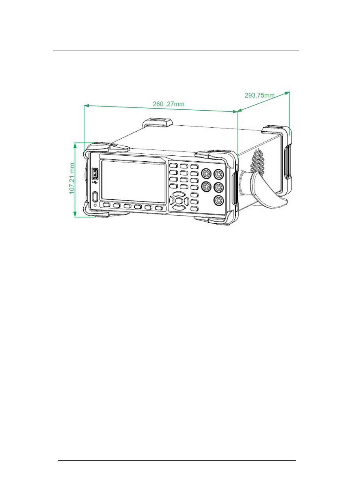
Appearance and Size
Diagram 1- 4 Appearance and Size
17
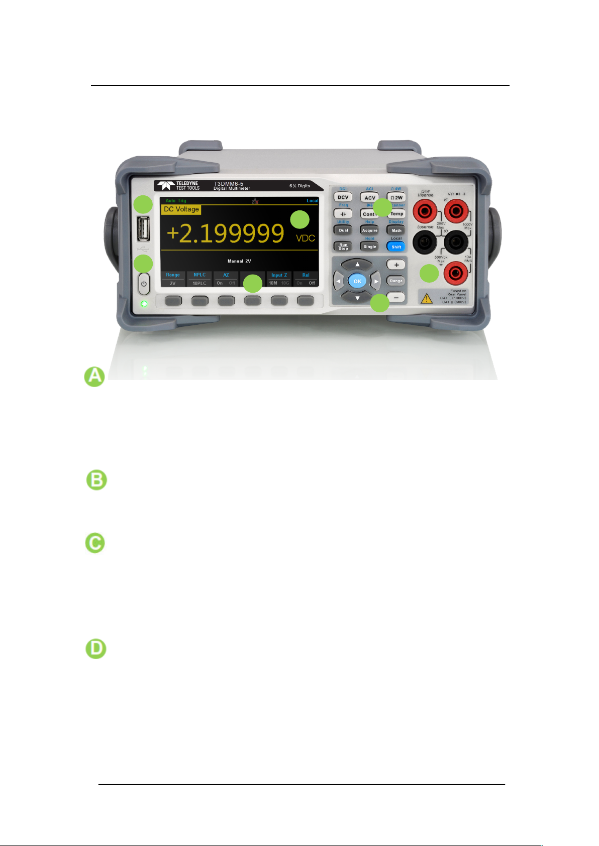
Front Panel
A
E
C
B
G
D
F
Diagram 1- 5 Front Panel Overview
• USB Host
By using this interface, users can store the current state or measurement
data into a USB storage device. Users can also read the state les or
updated rmware from the USB storage device.
• Power Key
Press the key to turn the instrument on/o.
• LCD Display
The instrument provides a 4.3 inch colour TFT-LCD display screen with
480*272 resolution that displays the current function menus,
measurement parameter settings, system status, prompt messages, etc.
• Menu Operation Keys
Press any softkey to activate the corresponding menu.
18
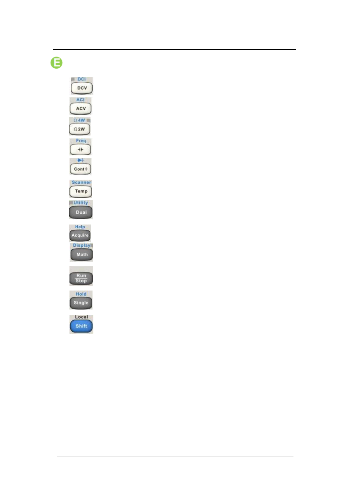
• Measurement and Assistant Function Keys
DC Voltage / Current Measurement
AC Voltage / Current Measurement
2-Wire / 4-Wire Resistance Measurement
Frequency / Capacitance Measurement
Continuity / Diode Test
Temperature Measurement /
Enable Multiple Scan Card Functions
Enable Dual-display Function / Set Up the Utility
Acquire Function / Help System
Math Function / Display Function
Auto Trigger / Stop
Single Trigger / Hold Measurement Function
Return to local control of the instrument (when in
Remote mode).
Some of the front panel keys have text above
them. This indicates that the key has a function
that you can access by pressing and
releasing【Shift】before pressing the key.
19
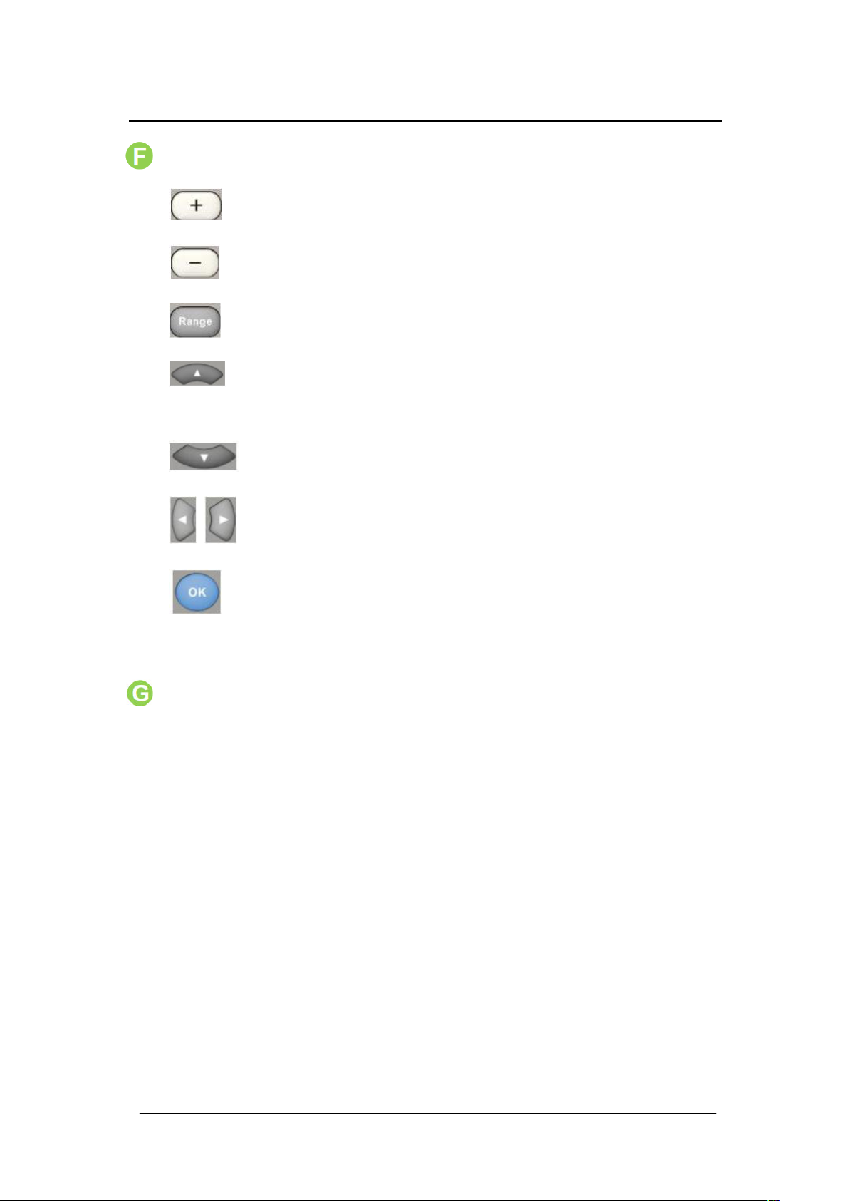
• Range and Direction Keys
Increase the measurement range
Decrease the measurement range
Select auto or manual range
Set up measurement parameter to Move the cursor page up
or down
Set up measurement parameter Move the cursor left or right
Apply the current setting
• Signal Input Terminals
The measured signal (device) will be connected into the multimeter
through these terminals. Dierent measurement objects have dierent
connection methods. For details, please refer to “Measurement
Connections”.
20

Back Panel
I. Power Socket
Diagram 1- 6 Back Panel Overview
Please use the power cord provided in the accessories to connect the
multimeter to the AC power through this socket.
Important Note: The correct voltage range must be selected rst
(through the Voltage Selector) before power connection.
II. Power Fuse
The multimeter is already installed with a power fuse before leaving the
factory. To replace a new one, please:
1. Turn o the multimeter and remove the power cord.
2. Press the block tongue down using a at head screwdriver (in the
direction of the dotted arrow in the Diagram 1 – 7 Change the fuse)
and pull out the fuse holder.
3. Select the proper voltage range.
4. Replace using the same specied fuse type and value.
5. Reinstall the fuse holder into the slot.
21
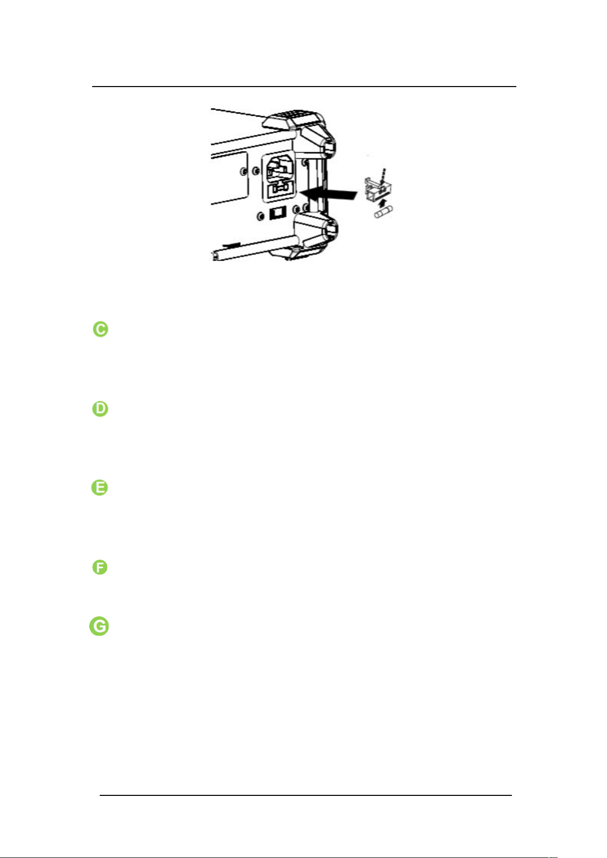
Diagram 1- 7 Change the fuse
C. AC Voltage Selector
Select a proper voltage range (110V or 220V) according to the local AC
supply.
D. Inspection card (option)
An optional 16-channel Data Acquisition Module will be installed in the
T3DMM6-5-SC instrument.
V. USB Device
Connect to a PC through the USB interface. You can use SCPI
commands or PC software to control the T3DMM6-5 remotely.
VI. LAN
The multimeter can be connected to the LAN network for remote control.
VII. VMC Output
The mutlimeter outputs a low-true pulse from the 【VM Comp】 connector
after every measurement
22

H. Ext trigger
Trigger the multimeter by connecting a trigger pulse through the 【
Ext Trig 】 connector. Note the external trigger source must be
selected.
I. Current Input Fuse
Before leaving the factory the multimeter is installed with a current
measurement fuse to provide 10A maximum input protection. To replace
with a new one, please:
1. Turn o the multimeter and remove the power cord.
2. Turn the fuse seat counter clockwise as shown in the
Diagram 1- 7 Change the fuse, using a straight screwdriver and
then pull out the fuse holder.
3. Replace with a new fuse as specied.
4. Reinstall the fuse holder into the slot.
• Instrument Lockhole
You can use the safety lock to lock the multimeter in a xed place if
necessary, using a Kensington lock.
23
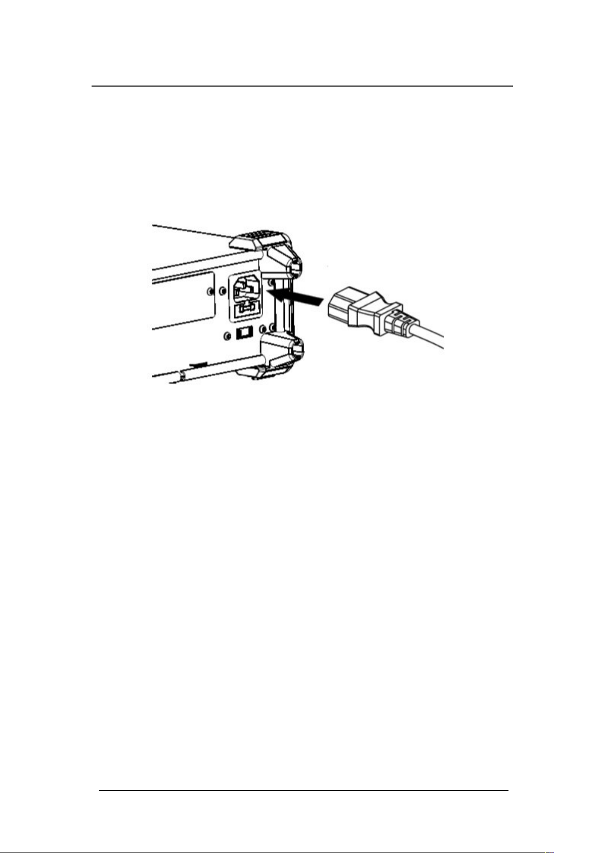
Start the Multimeter
Before you connect the instrument to a power source, please select the AC
voltage selector on the rear panel of your multimeter according to the power
supply. Then connect the power cord as shown in the below diagram.
Diagram 1- 8 Connect Power Cord
Press the Power key on the front panel to start up the multimeter. If the
multimeter does not starts normally, please:
1. Make sure the power cord is in properly connected and that the power
cord is good and in working condition.
2. Try to restart the multimeter, if it fails, check the power fuse and replace
with a new one if necessary.
3. If the problem still remains, please contact Teledyne Test Tools.
24
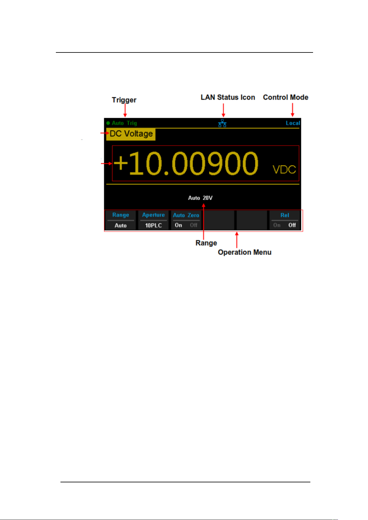
User Interface
Measurement
Measurement
Diagram 1- 9 User Interface
25
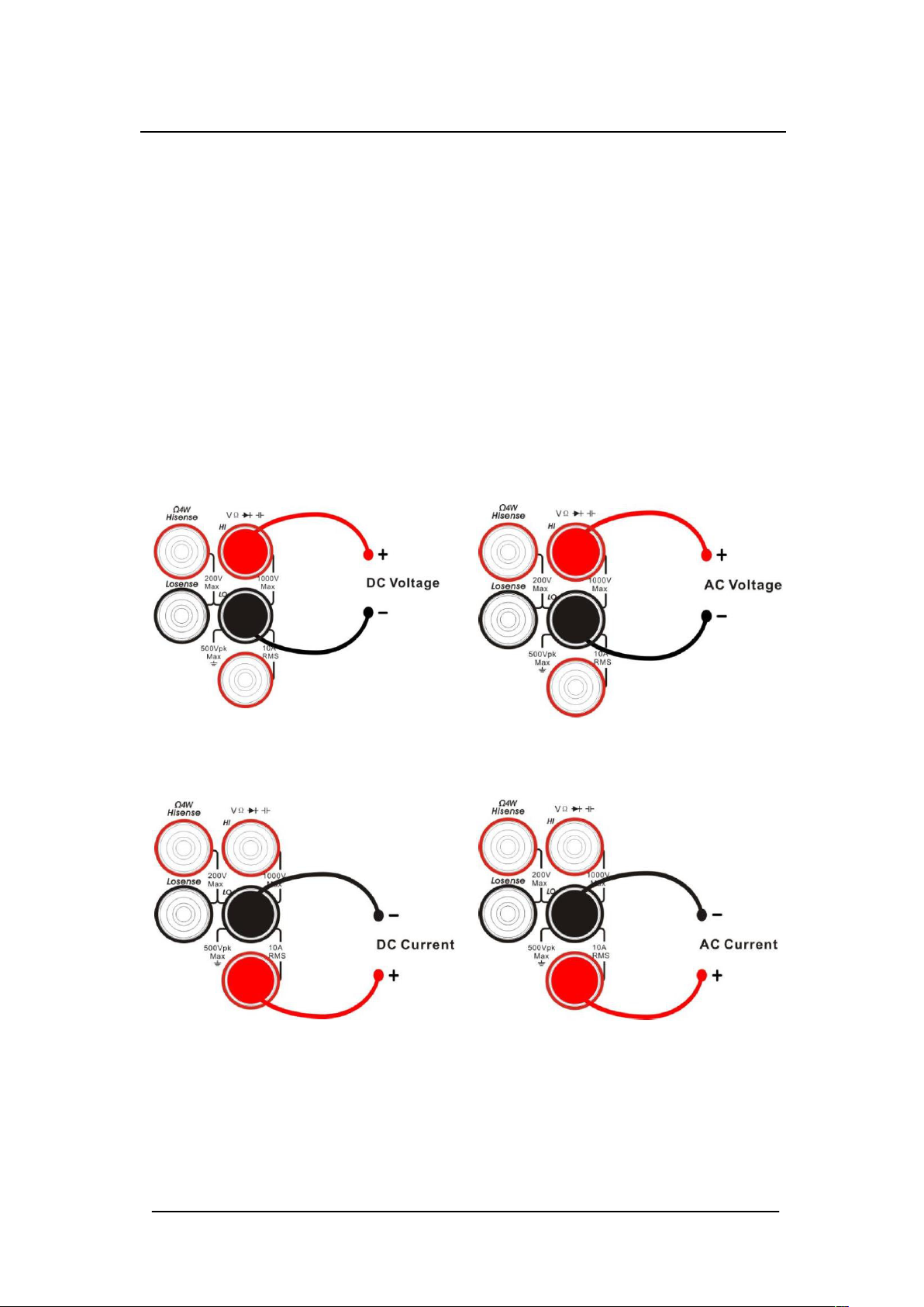
Measurement Connections
T3DMM6-5 is designed with many built in measurement functions. After
selecting the desired measurement function, please connect the signal
(device) under test to the multimeter according to the method
below. Do not switch the measurement function when measuring as it may
cause damage to the multimeter. For example, when the test leads are
connected to the related current terminals, AC voltage measurement should
not be selected.
DCV Measurement ACV Measurement
DCI Measurement ACI Measurement
26
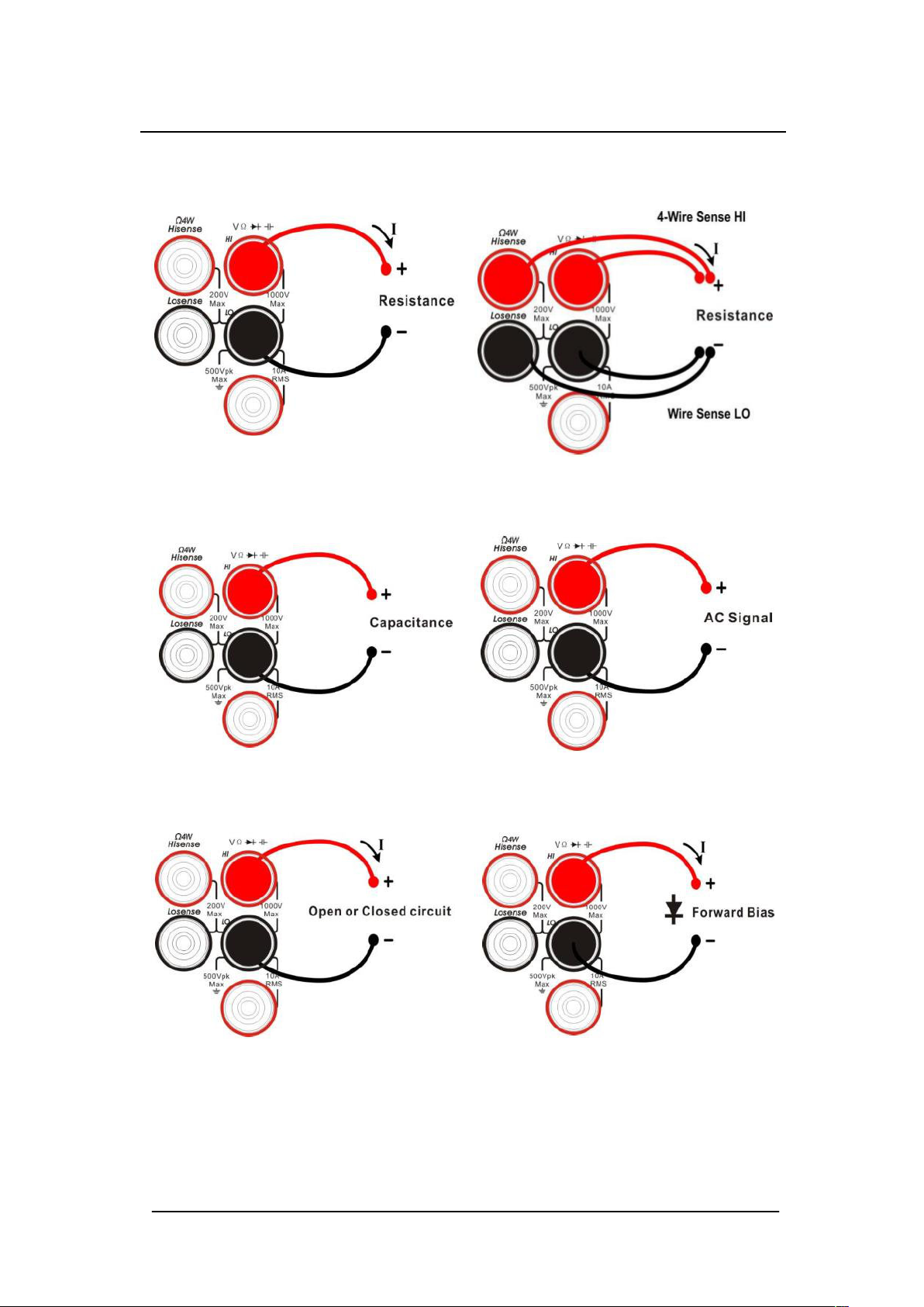
Resistance Measurement (2-wire) Resistance Measurement (4 wire)
Capacitance Measurement Frequency/Period Measurement
Continuity Measurement Diode Measurement
27

Temperature Measurement
For RTD and thermcouple sensors
28

To Use the Built-in Help System
To access built-in help information please press 【 shift】 +【Acquire】
to enter the help system; then use the direction keys to choose the help item
you want, nally press【OK】to obtain help information.
The common help information categories are listed as follows:
1. Basic Measurements.
2. Measuring Temperature.
3. Measuring Capacitance.
4. Math Function.
5. Dual-display Function.
6. Saving and Recalling Information.
7. Optional Multiple Scan Card.
8. The convention and Tips for using Softkeys.
9 . Technical Support.
29
 Loading...