

Teledyne T3DMM4-5, T3DMM5-5, T3DMM6-5 Quick Start Manual
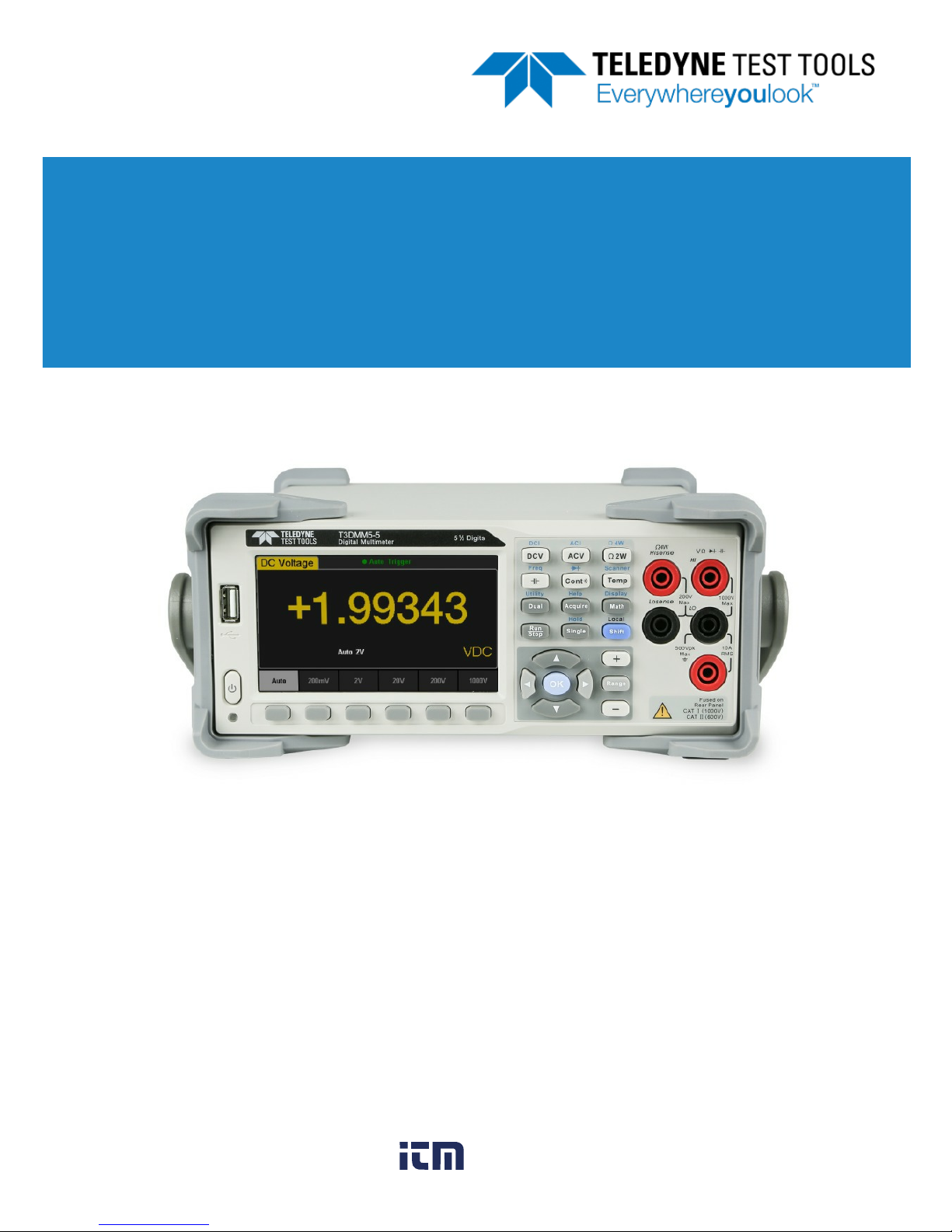
T3DMM4-5 / T3DMM5-5 / T3DMM6-5
4½, 5½ and 6½ Digit Digital Multimeters
Quick Start Guide
Version 1.1
September, 2018
www. .com
information@itm.com1.800.561.8187

© 2018 Teledyne LeCroy, Inc. All rights reserved.
Teledyne Test Tools is a brand and trademark of Teledyne LeCroy, Inc.
Other product or brand names are trademarks or requested trademarks
of their respective holders. Specifications, prices, availability and
delivery subject to change without notice.
Contents
General Safety Summary.............................................................. 1
Daily Maintenance and Cleaning.................................................. 7
General Inspection........................................................................ 8
Dimensions.................................................................................... 9
Front Panel ...................................................................................11
Rear Panel.....................................................................................14
Starting the Multimeter ............................................................... 17
User Interface............................................................................... 18
Measurement Connections ......................................................... 19
Connecting to USB and LAN Ports............................................ 22
Using the Built-in Help System...................................................23
Troubleshooting.......................................................................... 24
Handle Adjustment.......................................................................10
www. .com
information@itm.com1.800.561.8187

Quick Start 1
General Safety Summary
Read the following precautions carefully to avoid any personal
injuries, or damage to the instrument or products connected to it.
Use the instrument only as specified.
Use only the power cord supplied for the instrument.
Ground the instrument. The instrument is grounded through the
ground conductor of the power cord. To avoid electric shock,
always connect to grounded outlets. Make sure the instrument is
grounded correctly before connecting its input or output terminals.
Connect the signal wire correctly. To avoid damage, observe
input polarity and maximum voltage/current ratings at all times.
Observe all terminal ratings and signs on the instrument to
avoid fire or electric shock. Before connecting to the instrument,
read the manual to understand the input/output ratings.
Do not operate with suspected failures. If you suspect that the
instrument is damaged, contact the Teledyne LeCroy service
department immediately.
Do not operate in wet/damp conditions.
Do not operate in an explosive atmosphere.
Keep the surface of the instrument clean and dry.
Avoid touching exposed circuits or wires. Do not touch
exposed contacts or components when the power is on.
Do not operate without covers. Do not operate the instrument
with covers or panels removed.
Use only the fuse specified for the instrument.
Use proper overvoltage protection.
Use anti-static protection. Operate in an anti-static protected
area. Ground measurement cable conductors before connecting
to the instrument to discharge any static electricity before
connecting the cables to the instrument.
Observe ventilation requirements. Ensure good ventilation.
Check the vent and fan regularly to prevent overheating.
www. .com
information@itm.com1.800.561.8187
2 Quick Start
Safety Terms and Symbols
The following terms may appear on the instrument:
DANGER:
Direct injury or hazard may occur.
WARNING:
Potential injury or hazard may occur.
CAUTION:
Potential damage to instrument/property may occur.
CAT I
(1): IEC Measurement Category I, applicable for making
measurements on ‘other’ circuits that are not directly connected to
mains. See p. 6.
CAT II:
IEC Measurement Category II, applicable for making
measurements on circuits connected directly to utilization points
(socket outlets and similar points) of the low voltage mains installation.
See p. 5.
(1) CAT I as defined in IEC/EN 61010-031:2008. Note that
Measurement Category I was removed in IEC/EN 61010-031:2015
and replaced by ‘O’, indicating "other circuits that are not directly
connected to mains."
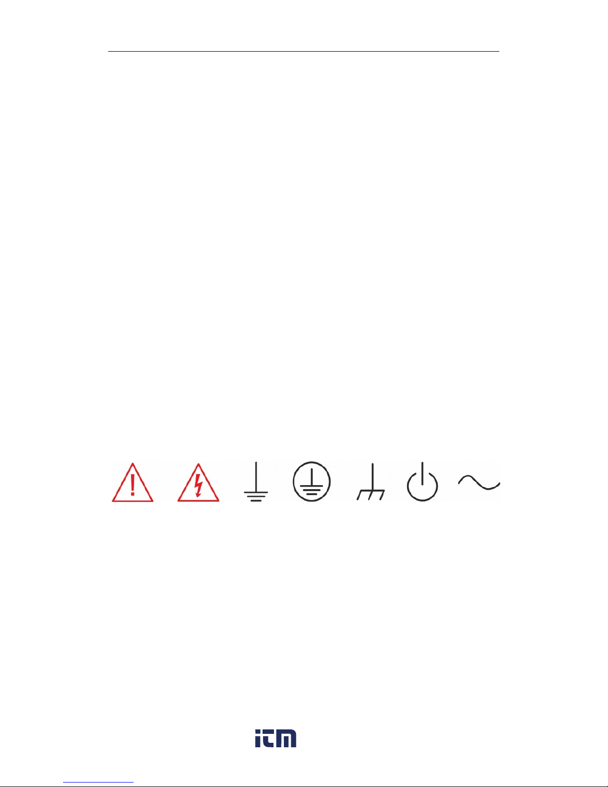
The following symbols may appear on the instrument:
CAUTION
Risk of
injury or
damage.
Refer to
manual.
WARNING
Risk of
electric
shock or
burn
Earth
Ground
Terminal
Protective
Conductor
Terminal
Frame or
Chassis
Terminal
ON/
Standby
Power
Alternating
Current
www. .com
information@itm.com1.800.561.8187

Quick Start 3
Operating Environment
Temperature: 0 °C to 40 °C
Humidity: 5% to 90% relative humidity (non-condensing) up to
+30 °C. Upper limit derates to 50% relative humidity (non-
condensing) at +40 °C.
Altitude: ≤ 2000 m
Use indoors only.
Pollution Degree 2. Use in an operating environment where
normally only dry, non-conductive pollution occurs. Temporary
conductivity caused by condensation should be expected.
AC Power
Input Voltage & Frequency: 100-120 V at 50/60 Hz
or 200-240 V at 50/60 Hz
Manual AC selection with a slide switch.
Power Consumption: 20 W maximum
Mains Supply Connector: CAT II per IEC/EN 61010-1:2010,
instrument intended to be supplied from the building wiring at
utilization points (socket outlets and similar).
Fuse Type
Current Input Terminal: 250 VAC F 10 A, 3 AG
AC Mains: 250 VAC F 300 mA, 5x20 mm
www. .com
information@itm.com1.800.561.8187

4 Quick Start
Input Terminal Protection Limitation
Protection limitation is defined for the input terminal.
1. Main Input (HI and LO) Terminals
HI and LO terminals are used for Voltage, Resistance,
Capacitance, Continuity, Frequency, Diode and Temperature
measurement. Two protection limitations are defined:
HI-LO protection limitation: 1000 VDC or 750 VAC. This is
the maximum measurable voltage. The limitation can be
expressed as 1000 Vpk.
LO ground protection limitation: LO terminal can “float” 500
Vpk relative to the ground safely. The maximum protection
limitation of HI terminal relative to the ground is 1000 Vpk.
Therefore, the sum of the “float” voltage and the measured
voltage can’t exceed 1000 Vpk.
2. Sampling (HISense and LOSense) Terminals
HISense and LOSense terminals are used for 4-wire Resistance
measurement. Two protection limitations are defined:
HISense-LOSense protection limitation: 2000 Vpk.
LOSense-LOSense protection limitation: 2 Vpk.
3. Current Input (I) Terminal
The I terminal is used for current measurement. The
maximum current which can go through the I terminal is
limited to 10 A by the fuse on the back panel.
NOTE:
Voltage on the current input terminal corresponds to voltage on
the LO terminal. To keep good protection, only use a fuse of the
specified type and value to replace this fuse.
www. .com
information@itm.com1.800.561.8187

Quick Start 5
IEC Measurement Category II Overvoltage Protection
To avoid the danger of electric shock, the Digital Multimeter
provides overvoltage protection for line-voltage mains
connections that meet both of the following conditions:
1. The HI and LO input terminals are connected to the mains
under Measurement Category
II conditions described in the
warning below.
2. The maximum line voltage of the mains does not exceed:
300 VAC for T3DMM4-5
600 VAC for T3DMM5-5 and T3DMM6-5
WARNING:
IEC Measurement Category II includes electrical devices
connected to mains at an outlet on a branch circuit, such as most
small appliances, test equipments, and other devices that
plug into a branch outlet or socket.
The multimeter is capable of making measurements with the HI
and LO inputs connected to mains in such devices (≤ 300 VAC
for T3DMM4-5 and ≤ 600 VAC for T3DMM5-5/T3DMM6-5) or to
the branch outlet itself.
However, the HI and LO terminals of the multimeter can’t be
connected to mains in permanently installed electrical devices
such as the main circuit-breaker panels, sub-panel disconnected
boxes and permanently wired motors. Such devices and circuits
are prone to exceed the protection limits of the multimeter.
www. .com
information@itm.com1.800.561.8187

6 Quick Start
Limits for Measurements on Other Circuits
Not Directly Connected to Mains
Max. rated input voltage: 1000 Vrms
Transient overvoltage: 4000 Vpk
WARNING:
Voltages above 300 VAC (for T3DMM4-5) or 600 VAC
(T3DMM5-5 / T3DMM6-5) can only be measured in circuits that
are isolated from mains. However, there may be transient over
voltage in circuits that are isolated from mains. The multimeter is
able to withstand occasional transient overvoltage up to 4000 Vpk.
Please don’t use this instrument to measure circuits where
transient overvoltage may exceed this level.
www. .com
information@itm.com1.800.561.8187

Daily Maintenance and Cleaning
Maintenance
Protect the liquid crystal display from direct sunlight when
storing or using the instrument.
NOTE:
To avoid damage to the instrument or test leads, please don’t
place them in mist, liquid or solvent.
Cleaning
Regularly clean the instrument and test leads.
● Wipe the external dust off the instrument and test leads using a
soft rag. Be careful not to scratch the display screen when
cleaning. Do not allow any liquid to enter the instrument.
● Use a damp soft rag to clean the instrument after removing the
power plug. Or use 75% isopropyl alcohol / water solvent to get
a more thorough cleaning.
NOTE:
To prevent the surface of the instrument or test leads from
damage, please don’t use any corrosive or chemical cleaning
reagents.
Please make sure the instrument is fully dry before
reconnecting the power to avoid short circuits or personal injury.
Quick Start 7
www. .com
information@itm.com1.800.561.8187
 Loading...