

Page 1

MODEL T360/T360M
CARBON DIOXIDE ANALYZER
Operation Manual
Also supports operation of:
T360U/GFC 7000E CO2 Analyzer
(when used in conjunction with T360U/GFC 7000E Addendum, PN 07273)
© Teledyne Advanced Pollution Instrumentation (TAPI)
9480 Carroll Park Drive
San Diego, CA 92121-5201
USA
Toll-free Phone: 800-324-5190
Phone: 858-657-9800
Fax: 858-657-9816
Email: api-sales@teledyne.com
Website: http://www.teledyne-api.com/
Copyright 2011-2012 07272B DCN6552
Teledyne Advanced Pollution Instrumentation 13 December 2012
Page 2

Page 3

07272B DCN6552
ABOUT TELEDYNE ADVANCED POLLUTION INSTRUMENTATION (TAPI)
Teledyne Advanced Pollution Instrumentation, Inc. (TAPI) is a worldwide market
leader in the design and manufacture of precision analytical instrumentation used
for air quality monitoring, continuous emissions monitoring, and specialty process
monitoring applications. Founded in San Diego, California, in 1988, TAPI
introduced a complete line of Air Quality Monitoring (AQM) instrumentation,
which comply with the United States Environmental Protection Administration
(EPA) and international requirements for the measurement of criteria pollutants,
including CO, SO2, NOX and Ozone.
Since 1988 TAPI has combined state-of-the-art technology, proven measuring
principles, stringent quality assurance systems and world class after-sales
support to deliver the best products and customer satisfaction in the business.
For further information on our company, our complete range of products, and the
applications that they serve, please visit www.teledyne-api.com or contact
sales@teledyne-api.com.
NOTICE OF COPYRIGHT
© 2011-2012 Teledyne Advanced Pollution Instrumentation. All rights reserved.
TRADEMARKS
All trademarks, registered trademarks, brand names or product names appearing
in this document are the property of their respective owners and are used herein
for identification purposes only.
i
Page 4

Model T360/T360M Operation Manual Teledyne API
07272B DCN6552
This page intentionally left blank.
ii
Page 5
07272B DCN6552
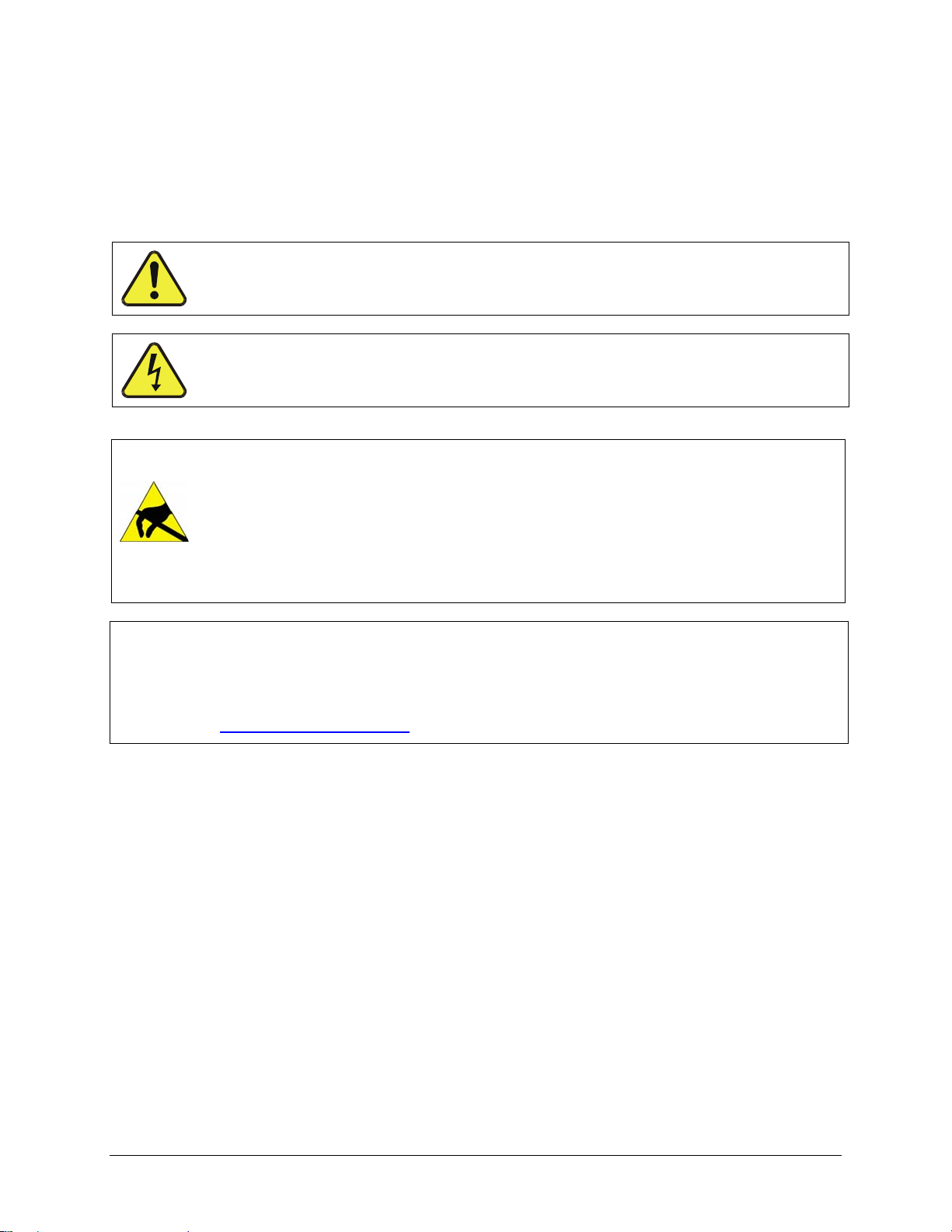
SAFETY MESSAGES
Important safety messages are provided throughout this manual for the purpose of avoiding personal
injury or instrument damage. Please read these messages carefully. Each safety message is associated
with a safety alert symbol, and are placed throughout this manual; the safety symbols are also located
inside the instrument.
descriptions of which are as follows:
It is imperative that you pay close attention to these messages, the
WARNING: Electrical Shock Hazard
HAZARD: Strong oxidizer
GENERAL WARNING/CAUTION: Read the accompanying message for
specific information.
CAUTION: Hot Surface Warning
Do Not Touch: Touching some parts of the instrument without
protection or proper tools could result in damage to the part(s) and/or the
instrument.
Technician Symbol: All operations marked with this symbol are to be
performed by qualified maintenance personnel only.
Electrical Ground: This symbol inside the instrument marks the central
safety grounding point for the instrument.
CAUTION
This instrument should only be used for the purpose and in the manner
described in this manual. If you use this instrument in a manner other tha
That for which it was intended, unpredictable behavior could ensue with
possible hazardous consequences.
NEVER use any gas analyzer to sample combustible gas(es)!
For Technical Assistance regarding the use and maintenance of this instrument or any
other Teledyne API product, contact Teledyne API’s Technical Support Department:
Telephone: 800-324-5190
Email: sda_techsupport@teledyne.com
or access any of the service options on our website at http://www.teledyne-api.com/
iii
Page 6
Model T360/T360M Operation Manual Teledyne API
07272B DCN6552
CONSIGNES DE SÉCURITÉ
Des consignes de sécurité importantes sont fournies tout au long du présent manuel dans le but d’éviter
des blessures corporelles ou d’endommager les instruments. Veuillez lire attentivement ces consignes.
Chaque consigne de sécurité est représentée par un pictogramme d’alerte de sécurité; ces pictogrammes
se retrouvent dans ce manuel et à l’intérieur des instruments. Les symboles correspondent aux
consignes suivantes :
AVERTISSEMENT : Risque de choc électrique
DANGER : Oxydant puissant
AVERTISSEMENT GÉNÉRAL / MISE EN GARDE : Lire la consigne
complémentaire pour des renseignements spécifiques
MISE EN GARDE : Surface chaude
Ne pas toucher : Toucher à certaines parties de l’instrument sans protection ou
sans les outils appropriés pourrait entraîner des dommages aux pièces ou à
l’instrument.
Pictogramme « technicien » : Toutes les opérations portant ce symbole doivent
être effectuées uniquement par du personnel de maintenance qualifié.
Mise à la terre : Ce symbole à l’intérieur de l’instrument détermine le point central
de la mise à la terre sécuritaire de l’instrument.
MISE EN GARDE
Cet instrument doit être utilisé aux fins décrites et de la manière décrite dans
ce manuel. Si vous utilisez cet instrument d’une autre manière que celle pour
laquelle il a été prévu, l’instrument pourrait se comporter de façon imprévisible
et entraîner des conséquences dangereuses.
NE JAMAIS utiliser un analyseur de gaz pour échantillonner des gaz
combustibles!
iv
Page 7
07272B DCN6552
WARRANTY
Warranty Policy (02024 F)
Teledyne Advanced Pollution Instrumentation (TAPI), a business unit of Teledyne
Instruments, Inc., provides that:
Prior to shipment, TAPI equipment is thoroughly inspected and tested. Should
equipment failure occur, TAPI assures its customers that prompt service and support
will be available.
COVERAGE
After the warranty period and throughout the equipment lifetime, TAPI stands ready
to provide on-site or in-plant service at reasonable rates similar to those of other
manufacturers in the industry. All maintenance and the first level of field
troubleshooting are to be performed by the customer.
NON-TAPI MANUFACTURED EQUIPMENT
Equipment provided but not manufactured by TAPI is warranted and will be repaired
to the extent and according to the current terms and conditions of the respective
equipment manufacturer’s warranty.
Product Return
All units or components returned to Teledyne API should be properly packed for
handling and returned freight prepaid to the nearest designated Service Center.
After the repair, the equipment will be returned, freight prepaid.
The complete Terms and Conditions of Sale can be reviewed at
http://www.teledyne-api.com/terms_and_conditions.asp
CAUTION – Avoid Warranty Invalidation
Failure to comply with proper anti-Electro-Static Discharge (ESD) handling and packing instructions
and Return Merchandise Authorization (RMA) procedures when returning parts for repair or
calibration may void your warranty. For anti-ESD handling and packing instructions please refer to
“Packing Components for Return” in the Primer on Electro-Static Discharge section of this manual,
and for RMA procedures please refer to our Website at http://www.teledyne-api.com
Customer Support > Return Authorization.
under
v
Page 8

Model T360/T360M Operation Manual Teledyne API
07272B DCN6552
This page intentionally left blank.
vi
Page 9

07272B DCN6552
ABOUT THIS MANUAL
This manual, PN 07272, provides operation instructions for Models T360 and T360M,
and supports operation of the Model T360U (when used in conjunction with the
T360U/GFC7000E Addendum, PN 07273). This manual is comprised of multiple
documents as listed below.
Part No. Rev Name/Description
07272 B T360 Carbon Dioxide Analyzer Operation Manual
05233 C Menu trees and software documentation (inserted as Appendix A of this manual)
06879
05235 C Repair Request Questionnaire (inserted as Appendix C of this manual)
0691201 B Interconnect Wire List (located in Appendix D of this manual)
06912 B Interconnect Wiring Diagram (located in Appendix D of this manual)
03297 K PCA, 03296, IR Photodetector Preamp and Sync Demodulator
03632 C PCA, 03631, 0-20mA driver
04003 N PCA, 04003, Pressure/Flow Transducer Interface
04089 A PCA, 04088, Opto Pickup Interface
04136 B PCA, 04135 Rev A, Relay
04468 B PCA, 04467, Analog Output Series Res
05803 B SCH, PCA 05802, MOTHERBOARD, GEN-5
06698 D SCH, PCA 06697, INTRFC, LCD TCH SCRN,
06882 B SCH, LVDS TRANSMITTER BOARD
06731 B SCH, AUXILLIARY-I/O BOARD
1/4/2011
Interconnects and Schematics included in Appendix D of this manual
Spare Parts List (located in Appendix B, this manual)
NOTE
Please read this manual in its entirety before making any attempt made to operate the instrument.
REVISION HISTORY
T360 Manual PN 07272
Date Rev DCN Change Summary
2012 Dec 13 B 6552 Administrative updates; minor technical updates
2011 Jan 12 A 5950 Initial Release
vii
Page 10

Model T360/T360M Operation Manual Teledyne API
07272B DCN6552
This page intentionally left blank.
viii
Page 11

07272B DCN6552
TABLE OF CONTENTS
ABOUT TELEDYNE ADVANCED POLLUTION INSTRUMENTATION (TAPI)................................................................. i
SAFETY MESSAGES .............................................................................................................................................. iii
CONSIGNES DE SÉCURITÉ................................................................................................................................... iv
WARRANTY.............................................................................................................................................................. v
ABOUT THIS MANUAL........................................................................................................................................... vii
TABLE OF CONTENTS ........................................................................................................................................... ix
1. INTRODUCTION......................................................................................................................................................17
1.1. Features ...........................................................................................................................................................17
1.2. Using This Manual............................................................................................................................................17
1.3. Options.............................................................................................................................................................18
2. SPECIFICATIONS AND APPROVALS...................................................................................................................21
2.1. Specifications ...................................................................................................................................................21
2.2. Approvals and Certifications.............................................................................................................................23
2.2.1. Safety .......................................................................................................................................................23
2.2.2. EMC..........................................................................................................................................................23
3. GETTING STARTED ...............................................................................................................................................25
3.1. Unpacking and Initial Set Up ............................................................................................................................25
3.2. Front Panel.......................................................................................................................................................27
3.3. Rear Panel .......................................................................................................................................................31
3.4. Internal Layout .................................................................................................................................................33
3.5. Electrical Connections......................................................................................................................................35
3.5.1. Power Connection ....................................................................................................................................35
3.5.2. Connecting Analog Inputs (Option 64B) ...................................................................................................36
3.5.3. Connecting Analog Outputs......................................................................................................................36
3.5.4. Connecting the Status Outputs.................................................................................................................38
3.5.5. Current Loop Analog Outputs (Option 41) ................................................................................................39
3.5.6. Connecting the Control Inputs ..................................................................................................................40
3.5.7. Connecting the Alarm Relay Option (OPT 61)..........................................................................................42
3.5.8. Connecting the Communications Interfaces .............................................................................................43
3.6. Pneumatic Connections ...................................................................................................................................44
3.6.1. Basic Pneumatic Connections .................................................................................................................. 44
3.6.2. Connections with Ambient Zero/Ambient Span Valve...............................................................................48
3.6.3. Connections with Ambient Zero/Pressurized Span Valve Option .............................................................50
3.6.4. Pneumatic Connections in Multipoint Calibration Applications..................................................................53
3.6.5. Setting the Internal Purge Air Pressure ....................................................................................................53
3.7. Initial Operation ................................................................................................................................................54
3.7.1. Startup ......................................................................................................................................................54
3.7.2. Warm Up...................................................................................................................................................55
3.7.3. Warning Messages ...................................................................................................................................55
3.7.4. Functional Checks ....................................................................................................................................57
3.8. Initial Calibration Procedure .............................................................................................................................58
3.8.1. Initial O2 Sensor Calibration Procedure ....................................................................................................61
4. OPERATING INSTRUCTIONS................................................................................................................................67
4.1. Overview of Operating Modes..........................................................................................................................67
4.2. Sample Mode ...................................................................................................................................................68
4.2.1. Test Functions ..........................................................................................................................................69
4.2.2. Warning Messages ...................................................................................................................................70
4.3. Calibration Mode ..............................................................................................................................................72
4.4. Setup Mode......................................................................................................................................................73
4.5. Setup CFG: Viewing the Analyzer’s Configuration Information.................................................................... 74
4.6. SETUP ACAL: Automatic Calibration ..........................................................................................................74
4.7. SETUP DAS: Using the Data Acquisition System (DAS).............................................................................75
4.7.1. DAS Structure...........................................................................................................................................76
4.7.2. Default DAS Channels..............................................................................................................................78
4.7.3. Remote DAS Configuration.......................................................................................................................94
4.8. SETUP RNGE: Analog Output Reporting Range Configuration ..................................................................95
4.8.1. Physical Range versus Analog Output Reporting Ranges........................................................................ 96
4.8.2. Reporting Range Modes...........................................................................................................................96
4.8.3. Single Range Mode (SNGL) ..................................................................................................................... 98
ix
Page 12

Teledyne API Model T360/T360M Operation Manual
07272B DCN6552
4.8.4. Dual Range Mode (DUAL)........................................................................................................................99
4.8.5. Auto Range Mode (AUTO)......................................................................................................................100
4.8.6. Range Units............................................................................................................................................101
4.8.7. Dilution Ratio ..........................................................................................................................................102
4.9. SETUP PASS: Password Feature .............................................................................................................103
4.10. SETUP CLK: Setting the Internal Time-of-Day Clock ..............................................................................105
4.11. SETUP MORE COMM: Using the Analyzer’s Communication Ports....................................................107
4.11.1. Machine ID............................................................................................................................................107
4.11.2. COM Port Default Settings....................................................................................................................108
4.11.3. RS-485 Configuration of COM2............................................................................................................111
4.11.4. DTE and DCE Communication .............................................................................................................111
4.11.5. COM Port Communication Modes ........................................................................................................112
4.11.6. Remote Access via the Ethernet...........................................................................................................114
4.11.7. USB Port Setup ....................................................................................................................................120
4.11.8. Multidrop RS-232 Setup .......................................................................................................................122
4.11.9. MODBUS Setup....................................................................................................................................125
4.11.10. COM Port Baud Rate..........................................................................................................................127
4.11.11. COM Port Testing ...............................................................................................................................128
4.12. SETUP MORE VARS: Internal Variables (VARS)...............................................................................129
4.13. SETUP MORE DIAG: Using the Diagnostics Functions.....................................................................131
4.13.1. Accessing the Diagnostic Features.......................................................................................................132
4.13.2. Signal I/O..............................................................................................................................................133
4.13.3. Analog Output Step Test ......................................................................................................................134
4.13.4. Analog I/O Configuration ......................................................................................................................135
4.13.5. Electric Test..........................................................................................................................................146
4.13.6. Dark Calibration Test............................................................................................................................147
4.13.7. Pressure Calibration .............................................................................................................................148
4.13.8. Flow Calibration....................................................................................................................................149
4.13.9. Test Channel Output.............................................................................................................................150
4.14. SETUP MORE ALRM: Using the Gas Concentration Alarms............................................................... 151
4.14.1. Setting the Concentration Alarm Limits................................................................................................. 151
4.15. Remote Operation of the Analyzer ...............................................................................................................152
4.15.1. Remote Operation Using the External Digital I/O..................................................................................152
4.15.2. Remote Operation Using the External Serial I/O ..................................................................................155
4.15.3. Additional Communications Documentation .........................................................................................161
4.15.4. Using the T360 with a Hessen Protocol Network..................................................................................162
5. CALIBRATION PROCEDURES ............................................................................................................................ 169
5.1. Before Calibration...........................................................................................................................................169
5.1.1. Zero Air and Span Gas ...........................................................................................................................169
5.1.2. Calibration Gas Traceability....................................................................................................................170
5.1.3. Data Recording Devices .........................................................................................................................170
5.2. Manual Calibration without Zero/Span Valves................................................................................................170
5.3. Manual Calibration Checks ............................................................................................................................173
5.4. Manual Calibration with Zero/Span Valves.....................................................................................................173
5.5. Manual Calibration Checks with Zero/Span Valves........................................................................................178
5.5.1. Zero/Span Calibration on Auto Range or Dual Ranges ..........................................................................179
5.5.2. Use of Zero/Span Valves with Remote Contact Closure ........................................................................180
5.6. Automatic Zero/Span Cal/Check (AutoCal) ....................................................................................................180
5.6.1. AutoCal with Auto or Dual Reporting Ranges Modes Selected ..............................................................183
5.7. Calibration Quality..........................................................................................................................................184
6. MAINTENANCE SCHEDULE AND PROCEDURES.............................................................................................185
6.1. Maintenance Schedule...................................................................................................................................185
6.2. Predicting Failures Using the Test Functions .................................................................................................189
6.3. Maintenance Procedures ...............................................................................................................................190
6.3.1. Replacing the Sample Particulate Filter..................................................................................................190
6.3.2. Rebuilding the Sample Pump .................................................................................................................191
6.3.3. Performing Leak Checks ........................................................................................................................191
6.3.4. Performing a Sample Flow Check ..........................................................................................................192
6.3.5. Cleaning the Optical Bench ....................................................................................................................192
6.3.6. Cleaning the Chassis..............................................................................................................................192
7. PRINCIPLES OF OPERATION .............................................................................................................................193
7.1. Measurement Method ....................................................................................................................................193
x
Page 13

Teledyne API Model T360/T360M Operation Manual
07272B DCN6552
7.1.1. Beer’s Law..............................................................................................................................................193
7.1.2. Measurement Fundamentals .................................................................................................................. 194
7.1.3. Gas Filter Correlation..............................................................................................................................194
7.1.4. Interference and Signal to Noise Rejection.............................................................................................197
7.2. Oxygen Sensor (OPT 65)...............................................................................................................................198
7.2.1. Paramagnetic Measurement of O2..........................................................................................................198
7.3. Pneumatic Operation......................................................................................................................................200
7.3.1. Sample Gas Flow ...................................................................................................................................200
7.3.2. Flow Rate Control...................................................................................................................................201
7.3.3. Purge Gas Pressure Control................................................................................................................... 202
7.3.4. Particulate Filter......................................................................................................................................202
7.3.5. Pneumatic Sensors.................................................................................................................................202
7.3.6. Pneumatic Operation of the O2 Sensor................................................................................................... 203
7.4. Electronic Operation.......................................................................................................................................204
7.4.1. Overview.................................................................................................................................................204
7.4.2. CPU ........................................................................................................................................................206
7.4.3. Optical Bench & GFC Wheel ..................................................................................................................207
7.4.4. Synchronous Demodulator (Sync/Demod) Assembly.............................................................................210
7.4.5. Relay Board............................................................................................................................................212
7.4.6. Motherboard ...........................................................................................................................................215
7.4.7. I2C Data Bus...........................................................................................................................................217
7.4.8. Power Supply/ Circuit Breaker................................................................................................................218
7.5. Front Panel Touchscreen/Display Interface ...................................................................................................219
7.5.1. LVDS Transmitter Board.........................................................................................................................219
7.5.2. Front Panel Touchscreen/Display Interface PCA....................................................................................219
7.6. Software Operation ........................................................................................................................................220
7.6.1. Adaptive Filter.........................................................................................................................................220
7.6.2. Calibration - Slope and Offset................................................................................................................. 221
7.6.3. Measurement Algorithm..........................................................................................................................221
7.6.4. Temperature and Pressure Compensation .............................................................................................222
7.6.5. Internal Data Acquisition System (DAS) .................................................................................................222
8. TROUBLESHOOTING AND SERVICE ................................................................................................................. 223
8.1. General Troubleshooting Hints....................................................................................................................... 223
8.1.1. Interpreting WARNING Messages..........................................................................................................224
8.1.2. Fault Diagnosis with TEST Functions .....................................................................................................228
8.1.3. Using the Diagnostic Signal I/O Function ...............................................................................................230
8.1.4. Internal Electronic Status LEDs ..............................................................................................................231
8.2. Gas Flow Problems........................................................................................................................................235
8.2.1. T360 Internal Gas Flow Diagrams ..........................................................................................................236
8.2.2. Typical Sample Gas Flow Problems.......................................................................................................238
8.2.3. Poor or Stopped Flow of Purge Gas.......................................................................................................240
8.3. Calibration Problems ......................................................................................................................................241
8.3.1. Miscalibrated...........................................................................................................................................241
8.3.2. Non-Repeatable Zero and Span.............................................................................................................242
8.3.3. Inability to Span – Touchscreen SPAN Button Not Visible .....................................................................242
8.3.4. Inability to Zero – Touchscreen ZERO Button Not Visible ......................................................................243
8.4. Other Performance Problems.........................................................................................................................244
8.4.1. Temperature Problems ........................................................................................................................... 244
8.4.2. Excessive Noise .....................................................................................................................................246
8.5. Subsystem Checkout .....................................................................................................................................247
8.5.1. AC Mains Configuration..........................................................................................................................247
8.5.2. DC Power Supply ...................................................................................................................................247
8.5.3. I2C Bus....................................................................................................................................................248
8.5.4. Touchscreen Interface ............................................................................................................................248
8.5.5. LCD Display Module ...............................................................................................................................249
8.5.6. Relay Board............................................................................................................................................249
8.5.7. Sensor Assembly....................................................................................................................................249
8.5.8. Motherboard ...........................................................................................................................................252
8.5.9. CPU ........................................................................................................................................................254
8.5.10. RS-232 Communications......................................................................................................................255
8.6. Repair Procedures .........................................................................................................................................256
8.6.1. Repairing Sample Flow Control Assembly..............................................................................................256
xi
Page 14

Teledyne API Model T360/T360M Operation Manual
07272B DCN6552
8.6.2. Removing/Replacing the GFC Wheel .....................................................................................................257
8.6.3. Disk-On-Module Replacement Procedure ..............................................................................................259
8.7. Frequently Asked Questions ..........................................................................................................................260
9. A PRIMER ON ELECTRO-STATIC DISCHARGE.................................................................................................263
9.1. How Static Charges are Created....................................................................................................................263
9.2. How Electro-Static Charges Cause Damage .................................................................................................264
9.3. Common Myths About ESD Damage.............................................................................................................265
9.4. Basic Principles of Static Control....................................................................................................................266
9.4.1. General Rules.........................................................................................................................................266
9.4.2. Basic anti-ESD Procedures for Analyzer Repair and Maintenance ........................................................268
LIST OF APPENDICES
APPENDIX A - SOFTWARE DOCUMENTATION
APPENDIX B - SPARE PARTS LIST
APPENDIX C - REPAIR QUESTIONNAIRE
APPENDIX D - ELECTRONIC SCHEMATICS
xii
Page 15

Teledyne API Model T360/T360M Operation Manual
07272B DCN6552
LIST OF FIGURES
Figure 3-1: Front Panel Layout ...................................................................................................................... 27
Figure 3-2: Display Screen and Touch Control .............................................................................................28
Figure 3-3: Display/Touch Control Screen Mapped to Menu Charts............................................................. 30
Figure 3-4: Rear Panel Layout....................................................................................................................... 31
Figure 3-5: Internal Chassis Layout...............................................................................................................33
Figure 3-6: Optical Bench Layout ..................................................................................................................34
Figure 3-7: Analog In Connector.................................................................................................................... 36
Figure 3-8: Current Loop Option Installed on the Motherboard..................................................................... 39
Figure 3-9: Control Inputs Power Connections.............................................................................................. 41
Figure 3-10: Alarm Relay Output Pin Assignments ......................................................................................... 42
Figure 3-11: Basic Internal Gas Flow ..............................................................................................................45
Figure 3-12: Pneumatic Connections–Basic Configuration–Using Bottled Span Gas ....................................46
Figure 3-13: Pneumatic Connections–Basic Configuration–Using Gas Dilution Calibrator ............................46
Figure 3-14: Pneumatic Connections with Ambient Zero/Ambient Span Valves (OPT 50A) .......................... 48
Figure 3-15: Pneumatic Connections with Ambient Zero/Ambient Span Valves (Opt 50A) and
External Zero Air Scrubber..........................................................................................................48
Figure 3-16: Internal Pneumatic Flow – Ambient Zero/Ambient Span ............................................................49
Figure 3-17: Pneumatic Connections with Ambient Zero/Pressurized Span Valves (OPT 50B) ....................50
Figure 3-18: Pneumatic Connections with Ambient Zero/Pressurized Span Valves (Opt 50B) and
External Zero Air Scrubber..........................................................................................................51
Figure 3-19: Internal Pneumatic Flow – Ambient Zero/Pressurized Span Valves...........................................52
Figure 3-20: Example of Pneumatic Set up for Multipoint Calibration.............................................................53
Figure 3-21: O2 Sensor Calibration Set Up..................................................................................................... 61
Figure 3-22: Internal Pneumatics with O2 Sensor Option 65 ..........................................................................62
Figure 4-1: Front Panel Display ..................................................................................................................... 67
Figure 4-2: Viewing TEST Functions ............................................................................................................. 70
Figure 4-3: Viewing and Clearing T360 WARNING Messages .....................................................................72
Figure 4-4: Default DAS Channels Setup......................................................................................................80
Figure 4-5: APICOM User Interface for DAS Configuration ..........................................................................94
Figure 4-6: Analog Output Connector Pin Out............................................................................................... 95
Figure 4-7: Rear Panel Connector Pin-Outs for COM1 & COM2 in RS-232 Mode..................................... 109
Figure 4-8: CPU Connector Pin-Outs for COM1 & COM2 in RS-232 Mode ...............................................110
Figure 4-9: Jumper and Cables for Multidrop Mode .................................................................................... 123
Figure 4-10: RS-232-Multidrop Host-to-Analyzer Interconnect Diagram....................................................... 124
Figure 4-11: Setup for Calibrating Analog Voltage Outputs ..........................................................................141
Figure 4-12: Setup for Calibrating Current Outputs.......................................................................................142
Figure 4-13: Status Output Connector...........................................................................................................152
Figure 4-14: Control Inputs ............................................................................................................................ 154
Figure 4-15: APICOM Remote Control Program Interface............................................................................ 161
Figure 5-1: Pneumatic Connections–Basic Configuration–Using Bottled Span Gas ..................................170
Figure 5-2: Pneumatic Connections–Basic Configuration–Using Gas Dilution Calibrator ..........................171
Figure 5-3: Pneumatic Connections – Ambient Zero/Pressurized Span Valves ........................................174
Figure 5-4: Pneumatic Connections – Ambient Zero/Pressurized Span Valves and External Zero Air
Scrubber.................................................................................................................................... 174
Figure 5-5: Pneumatic Connections – Ambient Zero/Ambient Span Valves............................................... 175
Figure 5-6: Pneumatic Connections – Ambient Zero/Ambient Span Valves with External Zero Air
Scrubber.................................................................................................................................... 175
Figure 6-1: Sample Particulate Filter Assembly ..........................................................................................190
Figure 7-1: Measurement Fundamentals.....................................................................................................194
Figure 7-2: GFC Wheel................................................................................................................................194
Figure 7-3: Measurement Fundamentals with GFC Wheel .........................................................................195
Figure 7-4: Affect of CO2 in the Sample on CO2 MEAS & CO2 REF.........................................................196
Figure 7-5: Effects of Interfering Gas on CO2 MEAS & CO2 REF.............................................................. 197
xiii
Page 16

Teledyne API Model T360/T360M Operation Manual
07272B DCN6552
Figure 7-6: Chopped IR Signal ....................................................................................................................197
Figure 7-7: Oxygen Sensor - Principle of Operation.................................................................................... 199
Figure 7-8: Internal Pneumatic Flow – Basic Configuration ........................................................................200
Figure 7-9: Flow Control Assembly & Critical Flow Orifice .......................................................................... 201
Figure 7-10: Gas Flow with O2 Sensor Option..............................................................................................203
Figure 7-11: T360 Electronic Block Diagram.................................................................................................205
Figure 7-12: CPU Board ................................................................................................................................206
Figure 7-13: GFC Light Mask ........................................................................................................................208
Figure 7-14: Segment Sensor and M/R Sensor Output................................................................................. 209
Figure 7-15: T360 Sync / Demod Block Diagram .......................................................................................... 210
Figure 7-16: Sample & Hold Timing...............................................................................................................211
Figure 7-17: Location of relay board Status LED’s........................................................................................214
Figure 7-18: Power Distribution Block Diagram............................................................................................. 218
Figure 7-19: Front Panel and Display Interface Block Diagram .................................................................... 219
Figure 7-20: Basic Software Operation..........................................................................................................220
Figure 8-1: Viewing and Clearing Warning Messages ................................................................................226
Figure 8-2: Example of Signal I/O Function.................................................................................................231
Figure 8-3: CPU Status Indicator.................................................................................................................232
Figure 8-4: Sync/Demod Board Status LED Locations ...............................................................................233
Figure 8-5: Relay Board Status LEDs.......................................................................................................... 233
Figure 8-6: T360 – Basic Internal Gas Flow ................................................................................................236
Figure 8-7: Internal Pneumatic Flow – Ambient Zero/Pressurized Span Valves.........................................237
Figure 8-8: Internal Pneumatic Flow – Ambient Zero/Ambient Span ..........................................................237
Figure 8-9: T360 – Internal Pneumatics with O2 Sensor Option 65A ..........................................................238
Figure 8-10: Critical Flow Restrictor Assembly Disassembly ........................................................................ 257
Figure 8-11: Opening the GFC Wheel Housing............................................................................................. 258
Figure 8-12: Removing the GFC Wheel ........................................................................................................258
Figure 9-1: Triboelectric Charging ...............................................................................................................263
Figure 9-2: Basic anti-ESD Work Station..................................................................................................... 266
LIST OF TABLES
Table 2-1: Model T360 Basic Unit Specifications.........................................................................................21
Table 2-2: Model T360M Basic Unit Specifications......................................................................................22
Table 3-1: Display and Touchscreen Control Description............................................................................ 29
Table 3-2: Rear Panel Description ...............................................................................................................32
Table 3-3: Analog Input Pin Assignments ....................................................................................................36
Table 3-4: T360 Analog Output Pin Outs .....................................................................................................37
Table 3-5: Status Output Pin-outs ................................................................................................................38
Table 3-6: Control Input Pin-outs..................................................................................................................41
Table 3-8: Concentration Alarm Relay Output Operation............................................................................. 42
Table 3-9: Ambient Zero/Ambient Span Valve Operating States.................................................................49
Table 3-10: Ambient Zero/Pressurized Span Valve Operating States ........................................................... 52
Table 3-11: Front Panel Display During System Warm-Up............................................................................ 55
Table 3-12: Possible Warning Messages at Start-Up ....................................................................................56
Table 4-1: Analyzer Operating Modes..........................................................................................................68
Table 4-2: Test Functions Defined ...............................................................................................................69
Table 4-3: List of Warning Messages........................................................................................................... 71
Table 4-4: Primary Setup Mode Features and Functions.............................................................................73
Table 4-5: Secondary Setup Mode Features and Functions........................................................................ 73
Table 4-6: Secondary Setup Mode Features and Functions........................................................................ 75
Table 4-7: DAS Data Channel Properties.....................................................................................................76
Table 4-8: DAS Data Parameter Functions..................................................................................................77
Table 6-9: Password Levels .......................................................................................................................103
Table 4-9: Com Port Communication Modes .............................................................................................112
xiv
Page 17

Teledyne API Model T360/T360M Operation Manual
07272B DCN6552
Table 4-10: Ethernet Status Indicators ................................................................................................................114
Table 4-11: LAN/Internet Configuration Properties.............................................................................................. 115
Table 4-12: Internet Configuration Touchscreen Functions.................................................................................119
Table 4-13: Variable Names (VARS) ................................................................................................................... 129
Table 4-14: T360 Diagnostic (DIAG) Functions...................................................................................................131
Table 4-15: DIAG - Analog I/O Functions ............................................................................................................135
Table 4-16: Analog Output Voltage Ranges ........................................................................................................135
Table 4-17: Analog Output Current Loop Range ................................................................................................. 136
Table 4-18: Analog Output Pin Assignments....................................................................................................... 136
Table 4-19: Voltage Tolerances for Analog Output Calibration ...........................................................................140
Table 4-20: Current Loop Output Calibration with Resistor................................................................................. 143
Table 4-21: Test Parameters Available for Analog Output A4.............................................................................150
Table 4-22: CO2 Concentration Alarm Default Settings ...................................................................................... 151
Table 4-23: Status Output Pin Assignments........................................................................................................153
Table 4-24: Control Input Pin Assignments .........................................................................................................154
Table 4-25: Terminal Mode Software Commands ...............................................................................................155
Table 4-26: Command Types ..............................................................................................................................156
Table 4-27: Serial Interface Documents ..............................................................................................................161
Table 4-28: RS-232 Com Parameters for Hessen Protocol.................................................................................162
Table 4-29: Teledyne API Hessen Protocol Response Modes............................................................................165
Table 4-30: Default Hessen Status Bit Assignments ...........................................................................................166
Table 5-1: AUTOCAL Modes ............................................................................................................................. 180
Table 5-2: AutoCal ATTRIBUTE Setup Parameters..........................................................................................180
Table 5-3 : Calibration Data Quality Evaluation.................................................................................................184
Table 6-1: T360 Maintenance Schedule............................................................................................................187
Table 6-2: T360 Test Function Record ..............................................................................................................188
Table 6-3: Predictive Uses for Test Functions...................................................................................................189
Table 7-1: Sync/Demod Status LED Activity...................................................................................................... 212
Table 7-2: Relay Board Status LED’s ................................................................................................................214
Table 8-1: Warning Messages - Indicated Failures .............................................................................................227
Table 8-2: Test Functions - Indicated Failures.....................................................................................................229
Table 8-3: Sync/Demod Board Status Failure Indications ................................................................................... 232
Table 8-4: I2C Status LED Failure Indications..................................................................................................... 233
Table 8-5: Relay Board Status LED Failure Indications ......................................................................................234
Table 8-6: DC Power Test Point and Wiring Color Codes................................................................................... 247
Table 8-7: DC Power Supply Acceptable Levels .................................................................................................248
Table 8-8: Relay Board Control Devices.............................................................................................................. 249
Table 8-9: Opto Pickup Board Nominal Output Frequencies............................................................................... 250
Table 8-10: Analog Output Test Function - Nominal Values Voltage Outputs ......................................................252
Table 8-11: Analog Output Test Function - Nominal Values Current Outputs.......................................................253
Table 8-12: Status Outputs Check.........................................................................................................................253
Table 9-1: Static Generation Voltages for Typical Activities ................................................................................ 264
Table 9-2: Sensitivity of Electronic Devices to Damage by ESD ......................................................................... 264
xv
Page 18

Teledyne API Model T360/T360M Operation Manual
07272B DCN6552
This page intentionally left blank.
xvi
Page 19

07272B DCN6552
1. INTRODUCTION
The Models T360 and T360M differ only in specifications; unless clearly
differentiated, both models in this manual are referred to as the T360 for
simplification. The T360/T360M measures carbon dioxide CO
infrared energy absorbed by a sample to that absorbed by a reference according to
the Beer-Lambert law. This is accomplished by using a Gas Filter Wheel which
alternately allows a high energy infrared (IR) light source to pass through a CO
filled chamber and a chamber with no CO
The IR light then travels through the sample cell, which has a folded path. Energy
loss through the sample cell is compared with the zero reference signal provided
by the gas filter to produce an output proportional to concentration, with little effect from
interfering gases within the sample. A nitrogen purge system is pro-vided for the
GFC wheel assembly to eliminate the effects of ambient CO
This design produces superior zero and span stability and a high signal-to-noise
ratio, allowing excellent sensitivity. Multi-tasking software gives real time
indication of numerous operating parameters and provides automatic alarms if
diagnostic limits are exceeded.
present.
2
by comparing
2
2
, if necessary.
2
1.1. FEATURES
The Models T360 and T360M include the following features:
Ranges,T360: 0-2 ppm to 0-2000 ppm, T360M: 0-4 ppm to 0-4000 ppm, user
selectable
Gas Filter Wheel for CO2 specific measurement
LCD Graphical User Interface with capacitive touch screen
Multi-tasking software allows viewing of test variables during operation
Continuous self checking with alarms
Bi-directional RS-232 and 10/100Base-T Ethernet (optional USB and RS-
485) ports for remote operation
Front panel USB ports for peripheral devices
Digital status outputs to indicate instrument operating condition
Adaptive signal filtering to optimize response time
Temperature & Pressure compensation
Internal data logging with 1 min to 24 hour averages
1.2. USING THIS MANUAL
The flowcharts in this manual contain typical representations of the analyzer’s
display during the various operations being described. These representations are
not intended to be exact and may differ slightly from the actual display of your
instrument.
17
Page 20
Introduction Teledyne API Model T360/T360M Operation Manual
07272B DCN6552
1.3. OPTIONS
Option
Pumps
Rack Mount Kits
Carrying Strap/Handle Side-mounted strap for hand-carrying analyzer
29
Option
Number
11 No pump (If one is standard either internal or external)
10A External Pump 100V – 120V/60Hz
10B External Pump 220V – 240V/50H
10C External Pump 220V – 240V/60Hz
10D External Pump 100V – 120V/50Hz
10E External Pump 100V /60Hz
13 High Voltage Internal Pump 240V/50Hz
Description/Notes
Pumps meet all typical AC power supply standards while exhibiting same
pneumatic performance.
Options for mounting the analyzer in standard 19” racks
20A Rack mount brackets with 26 in. (660 mm) chassis slides
20B Rack mount brackets with 24 in. (610 mm) chassis slides
21 Rack mount brackets only (compatible with carrying strap, Option 29)
23 Rack mount for external pump pack (no slides)
Extends from “flat” position to accommodate hand for carrying.
Recesses to 9mm (3/8”) dimension for storage.
Can be used with rack mount brackets, Option 21.
Cannot be used with rack mount slides.
CAUTION – GENERAL SAFETY HAZARD
THE T360 OR T360M ANALYZER WEIGHS ABOUT 18 KG (40 POUNDS).
TO AVOID PERSONAL INJURY WE RECOMMEND THAT TWO PERSONS LIFT AND CARRY
THE ANALYZER. DISCONNECT ALL CABLES AND TUBING FROM THE ANALYZER BEFORE
MOVING IT.
Analog Input and USB port
64B Also can be used for logging these signals in the analyzer’s internal DAS
Current Loop Analog
Outputs
41
Parts Kits Spare parts and expendables
Calibration Valves
50A
50B
42A
43
Used for connecting external voltage signals from other instrumentation (such as
meteorological instruments).
Adds isolated, voltage-to-current conversion circuitry to the analyzer’s analog
outputs.
Can be configured for any output range between 0 and 20 mA.
May be ordered separately for any of the analog outputs.
Can be installed at the factory or retrofitted in the field.
Expendables Kit for analyzer includes a recommended set of expendables for one
year of operation.
Expendables Kit for Internal Zero/Span, one year of operation.
Used to control the flow of calibration gases generated from external sources,
rather than manually switching the rear panel pneumatic connections.
AMBIENT ZERO AND AMBIENT SPAN VALVES
Zero Air and Span Gas input supplied at ambient pressure.
Gases controlled by 2 internal valves; SAMPLE/CAL & ZERO/SPAN.
AMBIENT ZERO AND PRESSURIZED SPAN VALVES
Zero Air supplied at ambient pressure. Span gas supplied from pressurized bottle of cal gas.
18
Page 21
Teledyne API Model T360/T360M Operation Manual Introduction
07272B DCN6552
Option
Communication Cables For remote serial, network and Internet communication with the analyzer.
Type Description
60A RS-232
60B RS-232 Shielded, straight-through DB-9F to DB-9F cable of about 1.8 m length.
60C Ethernet Patch cable, 2 meters long, used for Internet and LAN communications.
60D USB
USB Port For remote connection
64A
Concentration Alarm
Relays
61
RS-232 Multidrop Enables communications between host computer and up to eight analyzers.
62
Other Gas Options Second gas sensor and gas conditioners
65A Oxygen (O2) Sensor
Special Features Built in features, software activated
N/A
N/A
N/A
Option
Number
Description/Notes
Shielded, straight-through DB-9F to DB-25M cable, about 1.8 m long.
Used to interface with older computers or code activated switches with
DB-25 serial connectors.
Cable for direct connection between instrument (rear panel USB port) and
personal computer.
For connection to personal computer. (Separate option only when Option 64B, Analog
Input and USB Com Port, not elected).
Issues warning when gas concentration exceeds limits set by user.
Four (4) “dry contact” relays on the rear panel of the instrument. This relay option is
different from and in addition to the “Contact Closures” that come standard on all
TAPI instruments.
Multidrop card seated on the analyzer’s CPU card. Each instrument in the multidrop
network requres this card and a communications cable (Option 60B).
Maintenance Mode Switch, located inside the instrument, places the analyzer in
maintenance mode where it can continue sampling, yet ignore calibration, diagnostic,
and reset instrument commands. This feature is of particular use for instruments
connected to Multidrop or Hessen protocol networks.
Call Customer Service for activation.
Second Language Switch activates an alternate set of display messages in a
language other than the instrument’s default language.
Call Customer Service for a specially programmed Disk on Module containing the second
language.
Dilution Ratio Option allows the user to compensate for diluted sample gas, such as
in continuous emission monitoring (CEM) where the quality of gas in a smoke stack is
being tested and the sampling method used to remove the gas from the stack dilutes
the gas.
Call Customer Service for activation.
19
Page 22

Introduction Teledyne API Model T360/T360M Operation Manual
07272B DCN6552
This page intentionally left blank.
20
Page 23

07272B DCN6552
2. SPECIFICATIONS AND APPROVALS
2.1. SPECIFICATIONS
Table 2-1: Model T360 Basic Unit Specifications
T360 Parameter T360 Specification
Ranges
(Physical Analog Output)
Measurement Units ppb, ppm, µg/m3, mg/m3, % (user selectable)
Zero Noise < 0.1 ppm (RMS)
Span Noise < 1% of reading (RMS)
Lower Detectable Limit < 0.2 ppm1
Zero Drift (24 hours) <0.25 ppm1
Span Drift (24 hours) <0.5% of reading 1
Lag Time 10 seconds
Rise/Fall Time <60 seconds to 95%
Linearity 1% of full scale
Precision 0.5% of reading
Sample Flow Rate
Temperature Coefficient < 0.1% of Full Scale per oC
Voltage Coefficient < 0.05% of Full Scale per V
AC Power Rating 100V-120V, 60 Hz, (142 W) ; 220V – 240 V, 50 Hz (147 W)
Analog Output Ranges 10V, 5V, 1V, 0.1V (selectable)
Analog Output Resolution 1 part in 4096 of selected full-scale voltage
Recorder Offset
Standard I/O
Optional I/O
Environmental Installation category (over-voltage category) II; Pollution degree 2
Temperature Range 5-40oC
Humidity Range 0 - 95% RH, non-condensing
Dimensions H x W x D 7" x 17" x 23.5" (178 mm x 432 mm x 597 mm)
Weight 40 lbs. (18.1 kg)
1
At constant temperature and voltage.
Min: 0-2 ppm Full scale
Max: 0-2,000 ppm Full scale
Selectable, dual ranges and auto ranging supported
3
800cm
O
±10%
1 Ethernet: 10/100Base-T
2 RS-232 (300 – 115,200 baud)
2 USB device ports
8 opto-isolated digital status outputs
6 opto-isolated digital control inputs (3 defined, 3 spare)
4 analog outputs
1 USB com port
1 RS485
8 analog inputs (0-10V, 12-bit)
4 digital alarm outputs
Multidrop RS232
3 4-20mA current outputs
/min. ±10%
Sensor option adds 110 cm³/min, ±20%, to total flow through when installed.
2
21
Page 24

Specifications and Approvals Teledyne API Model T360/T360M Operation Manual
07272B DCN6552
Table 2-2: Model T360M Basic Unit Specifications
T360M Parameter T360M Specification
Ranges
(Physical Analog Output)
Measurement Units ppb, ppm, µg/m3, mg/m3, (selectable)
Zero Noise < 0.2 ppm (RMS)
Span Noise < 1% of reading (RMS)
Lower Detectable Limit < 0.4 ppm1
Zero Drift (24 hours) <0.5 ppm1
Span Drift (24 hours) <0.5% of reading1
Lag Time 10 seconds
Rise/Fall Time <60 seconds to 95%
Linearity 1% of full scale
Precision 0.5% of reading
Sample Flow Rate
Temperature Coefficient < 0.1% of Full Scale per oC or 0.1 ppm per oC, whichever is greater
Voltage Coefficient < 0.05% of Full Scale per V
AC Power Requirements 100V – 120V, 220V – 240V, 50/60 Hz
Analog Output Ranges 10V, 5V, 1V, 0.1V
Recorder Offset
Analog Output Resolution 1 part in 4096 of selected full-scale voltage
Standard I/O
Optional I/O
Operating Temperature Range 5-40oC
Humidity Range 0 - 95% RH, non-condensing
Dimensions H x W x D 7" x 17" x 23.5" (178 mm x 432 mm x 597 mm)
Weight 40 lbs. (18.1 kg)
Environmental Installation category (over-voltage category) II; Pollution degree 2
1
At constant temperature and voltage.
Min: 0-4 ppm Full scale
Max: 0-4000 ppm Full scale
Selectable, dual ranges and auto ranging supported
3
800cm
/min. ±10%
O2 Sensor option adds 110 cm³/min, ±20%, to total flow though when installed
±10%
1 Ethernet: 10/100Base-T
2 RS232 (300-115,200 baud)
2 USB device ports
8 Status opto-isolated digital status outputs
6 Opto-isolated digital control inputs (3 defined, 3 spare)
4 Analog outputs
1 USB com port
1 RS485
8 Analog inputs (0-10V, 12-bit)
4 Digital alarm outputs
Multidrop RS232
3 4-20mA current outputs
22
Page 25

Teledyne API Model T360/T360M Operation Manual Specifications and Approvals
07272B DCN6552
2.2. APPROVALS AND CERTIFICATIONS
The Teledyne Instruments Model T360 Gas Filter Correlation CO2 Analyzer was
tested and certified for Safety and Electromagnetic Compatibility (EMC). This
section presents the compliance statements for those requirements and directives.
2.2.1. Safety
IEC 61010-1:2001, Safety requirements for electrical equipment for
measurement, control, and laboratory use.
CE: 2006/95/EC, Low-Voltage Directive
North American:
cNEMKO (Canada): CAN/CSA-C22.2 No. 61010-1-04
NEMKO-CCL (US): UL No. 61010-1 (2nd Edition)
2.2.2. EMC
EN 61326-1 (IEC 61326-1), Class A Emissions/Industrial Immunity
EN 55011 (CISPR 11), Group 1, Class A Emissions
FCC 47 CFR Part 15B, Class A Emissions
CE: 2004/108/EC, Electromagnetic Compatibility Directive
23
Page 26

Specifications and Approvals Teledyne API Model T360/T360M Operation Manual
07272B DCN6552
This page intentionally left blank.
24
Page 27
07272B DCN6552
3. GETTING STARTED
3.1. UNPACKING AND INITIAL SET UP
CAUTION
To avoid personal injury, always use two persons to lift and carry the
Never disconnect PCAs, wiring harnesses or electronic subassemblies
Printed circuit assemblies (PCAs) are sensitive to electro-static
discharges too small to be felt by the human nervous system. Damage
resulting from failure to use ESD protection when working with
electronic assemblies will void the instrument warranty.
while the instrument is under power.
CAUTION – Avoid Warranty Invalidation
Model T360.
WARNING
See A Primer on Electro-Static Discharge in this manual for more information
on preventing ESD damage.
NOTE
It is recommended that you store shipping containers/materials for future use if/when the instrument should
be returned to the factory for repair and/or calibration service. See Warranty page in this manual and
shipping procedures on our Website at:
http://www.teledyne-api.com under Customer Support > Return Authorization.
1. Verify that there is no apparent external shipping damage. If damage has
occurred, please advise the shipper first, then Teledyne Instruments.
2. Included with your analyzer is a printed record of the final performance
characterization performed on your instrument at the factory. This record,
titled Final Test and Validation Data Sheet (P/N 04596) is an important
quality assurance and calibration record for this instrument. It should be
placed in the quality records file for this instrument.
3. Carefully remove the top cover of the analyzer and check for internal
shipping damage.
Remove the set-screw located in the top, center of the Front panel.
Remove the 2 screws fastening the top cover to the unit (one per side
towards the rear).
Slide the cover backwards until it clears the analyzer’s front bezel.
Lift the cover straight up.
25
Page 28

Getting Started Teledyne API Model T360/T360M Operation Manual
07272B DCN6552
4. Inspect the interior of the instrument to make sure all circuit boards and other
components are in good shape and properly seated.
5. Check the connectors of the various internal wiring harnesses and pneumatic
hoses to make sure they are firmly and properly seated.
6. Verify that all of the optional hardware ordered with the unit has been
installed. These are listed on the paperwork accompanying the analyzer.
7. VENTILATION CLEARANCE: Whether the analyzer is set up on a bench or
installed into an instrument rack, be sure to leave sufficient ventilation
clearance.
AREA MINIMUM REQUIRED CLEARANCE
Back of the instrument
4 in.
Sides of the instrument
Above and below the instrument
1 in.
1 in.
Various rack mount kits are available for this analyzer – please see Section 1.3.
26
Page 29
Teledyne API Model T360/T360M Operation Manual Getting Started
07272B DCN6552
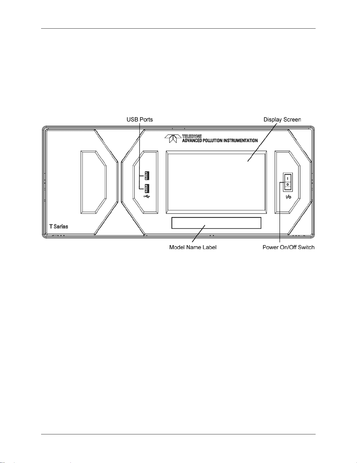
3.2. FRONT PANEL
Figure 3-1 shows the analyzer’s front panel layout, followed by a close-up of the
display screen in Figure 3-2, which is described in Table 3-1. The two USB ports
on the front panel are provided for the connection of peripheral devices:
plug-in mouse (not included) to be used as an alternative to the touchscreen
interface
thumb drive (not included) to download updates to instruction software
(contact TAPI Technical Support for information).
Figure 3-1: Front Panel Layout
27
Page 30
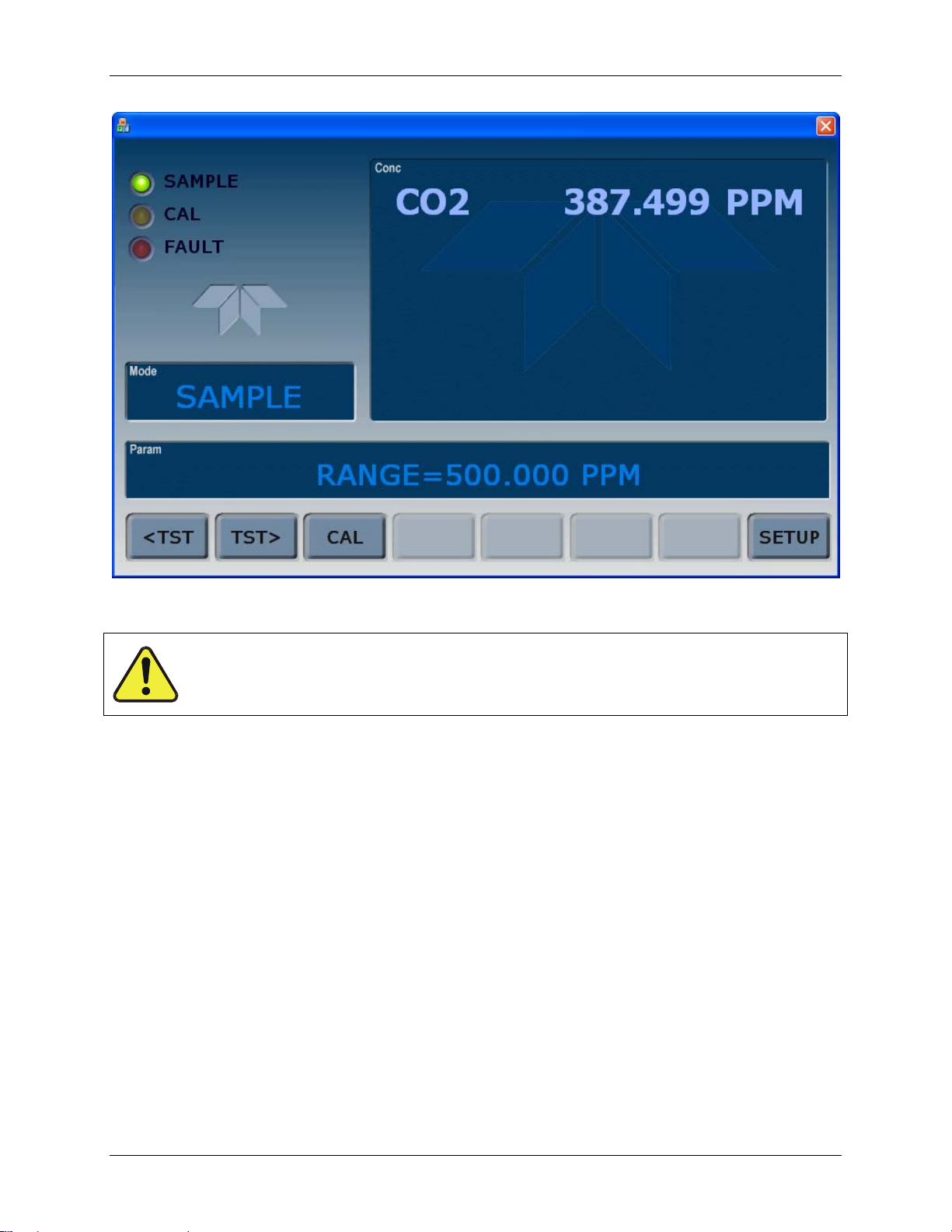
Getting Started Teledyne API Model T360/T360M Operation Manual
07272B DCN6552
Figure 3-2: Display Screen and Touch Control
CAUTION – Avoid Damaging Touchscreen
Do not use hard-surfaced instruments such as pens to operate the
touchscreen.
The front panel liquid crystal display includes touch control. Upon analyzer startup, the display shows a splash screen and other initialization indicators before the
main display appears, similar to Figure 3-2 above (may or may not display a Fault
). The LEDs on the display screen indicate the Sample, Calibration and
alarm
Fault states; also on the screen is the gas concentration field (Conc), which
displays real-time readouts for the primary gas and for the secondary gas if
installed. The display screen also shows which mode the analyzer is currently in
(Mode field), as well as messages and data (Param field). Along the bottom of the
screen is a row of touch control buttons; only those that are currently applicable
will have a label. Table 3-1 provides detailed information for each com
ponent of
the screen.
28
Page 31

Teledyne API Model T360/T360M Operation Manual Getting Started
07272B DCN6552
Table 3-1: Display and Touchscreen Control Description
Field Description/Function
Status
Conc
Mode Displays the name of the analyzer’s current operating mode
Param
Control Buttons Displays dynamic, context sensitive labels on each button, which is blank when inactive until applicable.
LEDs indicating the states of Sample, Calibration and Fault, as follows:
Name Color State Definition
Off
On
SAMPLE Green
CAL Yellow
FAULT Red
Displays the actual concentration of the sample gas currently being measured by the analyzer in the
currently selected units of measure
Displays a variety of informational messages such as warning messages, operational data, test function
values and response messages during interactive tasks.
Blinking
Off
On
Blinking
Off
Blinking
Unit is not operating in sample mode, DAS is disabled.
Sample Mode active; Front Panel Display being updated; DAS data
being stored.
Unit is operating in sample mode, front panel display being updated,
DAS hold-off mode is ON, DAS disabled
Auto Cal disabled
Auto Cal enabled
Unit is in calibration mode
No warnings exist
Warnings exist
Figure 3-3 shows how the front panel display is mapped to the menu charts
illustrated in this manual. The Mode, Param (parameters), and Conc (gas
concentration) fields in the display screen are represented across the top row of
each menu chart. The eight touchscreen control buttons along the bottom of the
display screen are represented in the bottom row of each menu chart.
29
Page 32

Getting Started Teledyne API Model T360/T360M Operation Manual
07272B DCN6552
Figure 3-3: Display/Touch Control Screen Mapped to Menu Charts
30
Page 33

Teledyne API Model T360/T360M Operation Manual Getting Started
07272B DCN6552
3.3. REAR PANEL
Figure 3-4: Rear Panel Layout
Table 3-2 provides a description of each component on the rear panel
31
Page 34

Getting Started Teledyne API Model T360/T360M Operation Manual
07272B DCN6552
Table 3-2: Rear Panel Description
Component Function
cooling fan
AC power
connector
Model/specs label
PURGE IN
SAMPLE
EXHAUST
VENT SPAN
PRESSURE SPAN
RX TX
COM 2
RS-232
DCE DTE
STATUS
ANALOG OUT
CONTROL IN
ALARM
ETHERNET
ANALOG IN
USB
Information Label
Pulls ambient air into chassis through side vents and exhausts through rear
Connector for three-prong cord to apply AC power to the analyzer
CAUTION! The cord’s power specifications (specs) MUST comply with the power
specs on the analyzer’s rear panel Model number label
Identifies the analyzer model number and provides power specs
Connect a source of dried air that has been scrubbed of CO2. This inlet supplies
purge air to the GFC wheel housing (Section 7.1.3.1). (Also see Section 8.2.3).
Connect a gas line from the source of sample gas here.
Calibration gases are also inlet here on units without zero/span valve options installed.
Connect an exhaust gas line of not more than 10 meters long here that leads outside
the shelter or immediate area surrounding the instrument.
Span gas vent outlet for units with zero/span valve options installed.
Connect an exhaust gas line of not more than 10 meters long here.
On units with zero/span valve options installed, connect a gas line to the source of
calibrated span gas here.
Internal Zero Air: On units with zero/span valve options installed but no internal zero
IZS
air scrubber, attach a gas line to the source of zero air here.
LEDs indicate receive (RX) and transmit (TX) activity on the when blinking.
Serial communications port for RS-232 or RS-485.
Serial communications port for RS-232 only.
Switch to select either data terminal equipment or data communication equipment
during RS-232 communication.
For outputs to devices such as Programmable Logic Controllers (PLCs).
For voltage or current loop outputs to a strip chart recorder and/or a data logger.
For remotely activating the zero and span calibration modes.
Option for concentration alarms and system warnings.
Connector for network or Internet remote communication, using Ethernet cable.
Option for external voltage signals from other instrumentation and for logging these
signals.
Com port optional connector for direct connection to laptop computer, using USB cable.
Includes voltage and frequency specifications.
32
Page 35

Teledyne API Model T360/T360M Operation Manual Getting Started
07272B DCN6552
3.4. INTERNAL LAYOUT
Figure 3-5 shows a top-down view of the analyzer.
Figure 3-5: Internal Chassis Layout
33
Page 36

Getting Started Teledyne API Model T360/T360M Operation Manual
07272B DCN6552
Opto-Pickup
PCA
Sync/Demod PCA
Housing
Sample Gas Flow
Sensor
Sample Gas Outlet
fitting
Sample Chamber
Pressure Sensor(s)
Bench
Temperature
Thermistor
Shock Absorbing
Mounting Bracket
Purge Gas
Pressure Regulator
IR Source
GFC Wheel
Heat Sync
GFC Temperature
Sensor
GFC Wheel Motor
Purge Gas
Inlet
GFC Heater
Figure 3-6: Optical Bench Layout
34
Page 37

Teledyne API Model T360/T360M Operation Manual Getting Started
07272B DCN6552
3.5. ELECTRICAL CONNECTIONS
WARNING
Never disconnect PCAs, wiring harnesses or electronic subassemblies
To maintain compliance with EMC standards, it is required that the cable length be no greater than 3
meters for all I/O connections, which include Analog In, Analog Out, Status Out, Control In, Ethernet/LAN,
USB, RS-232, and RS-485.
Refer to Figure 3-4 for the locations of the rear panel connections.
3.5.1. Power Connection
Power connection must have functioning ground connection.
Turn off analyzer power before disconnecting or
while the instrument is under power.
NOTE
WARNING
Do not defeat the ground wire on power plug.
connecting electrical subassemblies.
Do not operate with cover off.
CAUTION
Check the voltage and frequency specifications on the rear panel Model
Label for compatibility with the local power before plugging the analyzer
Do not plug in the power cord if the voltage or frequency is incorrect.
into line power.
The T360 analyzer can be configured for both 100-130 V and 210-240 V at either
50 or 60 Hz. To avoid damage to your analyzer, make sure that the AC power
voltage matches the voltage indicated on the rear panel serial number label and
that the frequency is between 47 and 63 Hz.
Attach the power cord to the analyzer and plug it into a power outlet capable of
carrying at least 10 A current at your AC voltage and that it is equipped with a
functioning earth ground.
35
Page 38
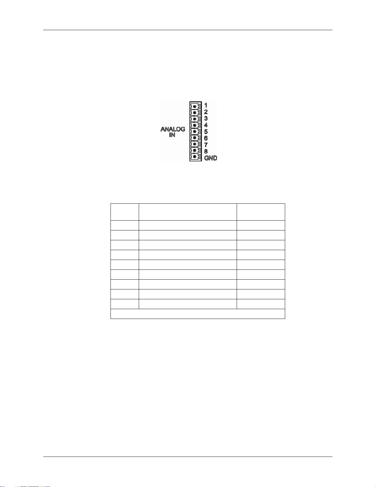
Getting Started Teledyne API Model T360/T360M Operation Manual
07272B DCN6552
3.5.2. Connecting Analog Inputs (Option 64B)
The Analog In connector is used for connecting external voltage signals from
other instrumentation (such as meteorological instruments) and for logging these
signals in the analyzer’s internal data acquisition system (DAS). The input
voltage range for each analog input is 0-10 VDC, and the input impedance is
nominally 20kΩ in parallel with 0.1µF.
Figure 3-7: Analog In Connector
Pin assignments for the Analog In connector are presented in Table 3-3.
Table 3-3: Analog Input Pin Assignments
PIN DESCRIPTION
1 Analog input # 1 AIN 1
2 Analog input # 2 AIN 2
3 Analog input # 3 AIN 3
4 Analog input # 4 AIN 4
5 Analog input # 5 AIN 5
6 Analog input # 6 AIN 6
7 Analog input # 7 AIN 7
8 Analog input # 8 AIN 8
GND Analog input Ground N/A
1
See Section 4.7 for details on setting up the DAS.
DAS
PARAMETER
1
3.5.3. Connecting Analog Outputs
The T360 is equipped with several analog output channels accessible through a
connector on the back panel of the instrument. The standard configuration for
these outputs is mVDC. An optional current loop output is available for each.
When the instrument is in its default configuration, channels A1 and A2 output a
signal that is proportional to the CO
be used for connecting the analog output signal to a chart recorder or for
interfacing with a data logger.
Output A3 is only used if the optional O
Channel A4 is special. It can be set by the user (see Section 4.13.9) to output any
one of the para
36
meters accessible through the <TST TST> menu (Table 4-2).
concentration of the sample gas. Either can
2
sensor is installed.
2
Page 39

Teledyne API Model T360/T360M Operation Manual Getting Started
A
07272B DCN6552
To access these signals attach a strip chart recorder and/or data-logger to the
appropriate analog output connections on the rear panel of the analyzer.
A1 A2 A3
ANALOG
4
1 2 3 4 5 6 7 8
Pin-outs for the analog output connector at the rear panel of the instrument are:
Table 3-4: T360 Analog Output Pin Outs
PIN ANALOG OUTPUT VDC SIGNAL MADC SIGNAL
1 V Out I Out +
2
3 V Out I Out +
4
5 V Out I Out +
6
7 V Out Not used
8
(Only used if O2 sensor
A1
A2
A3
is installed)
A4
Ground I Out -
Ground I Out -
Ground I Out -
Ground Not used
The default analog output voltage setting of the analyzer is 0 – 5 VDC
with a range of 0 – 500 ppm.
To change these settings, see Sections 4.13.4 and 4.8 respectively.
37
Page 40

Getting Started Teledyne API Model T360/T360M Operation Manual
07272B DCN6552
3.5.4. Connecting the Status Outputs
If you wish utilize the analyzer’s status outputs to interface with a device that
accepts logic-level digital inputs, such as programmable logic controllers (PLC’s)
they are accessed via a 12-pin connector on the analyzer’s rear panel labeled
STATUS.
STATUS
1 2 3 4 5 6 7 8 D
+
NOTE
Most PLC’s have internal provisions for limiting the current the input will draw. When connecting
to a unit that does not have this feature, external resistors must be used to limit the current
through the individual transistor outputs to ≤50mA (120 Ω for 5V supply).
The pin assignments for the status outputs can be found in the table below:
Table 3-5: Status Output Pin-outs
OUTPUT #
1
2
3
4
5
6
7
8
D EMITTER BUS The emitters of the transistors on pins 1-8 are bused together.
+ DC POWER + 5 VDC
STATUS
DEFINITION
SYSTEM OK
CONC VALID
HIGH RANGE
ZERO CAL
SPAN CAL
DIAG MODE
ALARM1
ALARM2
CONDITION
On if no faults are present.
On if CO2 concentration measurement is valid.
If the CO
On if unit is in high range of DUAL or AUTO range modes.
On whenever the instruments ZERO point is being calibrated.
On whenever the instruments SPAN point is being calibrated.
On whenever the instrument is in DIAGNOSTIC mode.
On whenever the measured CO
ALM1
On whenever the measured CO
ALM2
concentration measurement is invalid, this bit is OFF.
2
concentration is above the set point for
2
concentration is above the set point for
2
Digital Ground The ground level from the analyzer’s internal DC power supplies.
38
Page 41

Teledyne API Model T360/T360M Operation Manual Getting Started
07272B DCN6552
3.5.5. Current Loop Analog Outputs (Option 41)
This option adds isolated, voltage-to-current conversion circuitry to the
analyzer’s analog outputs. This option may be ordered separately for any of the
analog outputs; it can be installed at the factory or added later. Call TAPI sales
for pricing and availability.
The current loop option can be configured for any output range between 0 and
20 mA. Figure 3-8 provides installation instructions and illustrates a sample
bination of one current output and two voltage outputs configuration.
com
Information on calibrating or adjusting these outputs can be found in Section
4.13.4.3.
Figure 3-8: Current Loop Option Installed on the Motherboard
39
Page 42

Getting Started Teledyne API Model T360/T360M Operation Manual
07272B DCN6552
3.5.5.1. CONVERTING CURRENT LOOP ANALOG OUTPUTS TO STANDARD
VOLTAGE OUTPUTS
NOTE
Servicing or handling of circuit components requires electrostatic discharge protection, i.e. ESD
grounding straps, mats and containers. Failure to use ESD protection when working with
electronic assemblies will void the instrument warranty.
See Section 9 for more information on preventing ESD damage.
To convert an output configured for current loop operation to the standard 0 to 5
VDC output operation:
1. Turn off power to the analyzer.
2. If a recording device was connected to the output being modified,
disconnect it.
3. Remove the top cover
Remove the set screw located in the top, center of the rear panel
Remove the screws fastening the top cover to the unit (four per side).
Slide the cover back and lift straight up .
4. Disconnect the current loop option PCA from the appropriate connector on
the motherboard (see Figure 3-8).
5. Place a shunt
Figure 3-8).
6. Reatta
7. The analyzer is now ready to have a voltage-sensing, recording device
ch the top case to the analyzer.
attached to that output
between the leftmost two pins of the connector (see
3.5.6. Connecting the Control Inputs
If you wish to use the analyzer to remotely activate the zero and span calibration
modes, several digital control inputs are provided through a 10-pin connector
labeled CONTROL IN on the analyzer’s rear panel.
There are two methods for energizing the control inputs. The internal +5V
available from the pin labeled “+” is the most convenient method. However, if
full isolation is required, an external 5 VDC power supply should be used.
40
Page 43

Teledyne API Model T360/T360M Operation Manual Getting Started
07272B DCN6552
CONTROL IN
A B C D E F U +
S
Z
P
E
A
R
N
O
Local Power Connections
A B C D E F U +
Z
E
R
O
Figure 3-9: Control Inputs Power Connections
The pin assignments for the digital control inputs can be found in the table below:
Table 3-6: Control Input Pin-outs
INPUT # STATUS DEFINITION ON CONDITION
A
B
C
D
E
F
U
+
REMOTE ZERO CAL
REMOTE
SPAN CAL
SPARE
SPARE
SPARE
SPARE
Digital Ground May be connected to the ground of the data logger/recorder.
Pull-up supply for
inputs
Internal +5V Supply
The Analyzer is placed in Zero Calibration mode. The mode field of
the display will read ZERO CAL R.
The Analyzer is placed in Span Calibration mode. The mode field of
the display will read SPAN CAL R.
Input pin for +5 VDC required to activate pins A – F. This can be from
an external source or from the “+” pin of the instruments STATUS
connector.
Internal source of +5V which can be used to actuate control inputs
when connected to the U pin.
CONTROL IN
S
P
A
N
5 VDC Power
-
Supply
External Power Connections
+
41
Page 44

Getting Started Teledyne API Model T360/T360M Operation Manual
07272B DCN6552
3.5.7. Connecting the Alarm Relay Option (OPT 61)
Option 61 consists of a set of 2 concentration alarms. Each alarm can be
independently enabled or disabled as well as programmed with its own,
individual alarm limit point (see Section 4.14 for details on programming the
alarms).
The status of each alar
m is available via a set of alarm relay outputs located in the
lower right quadrant of the analyzer’s rear panel (see Figure 3-4). While there are
four relay outputs on t
he back of the analyzer, only two of the outputs correspond
to the instrument’s two concentration alarms.
Table 3-7: Alarm Relay Output Assignments
RELAY NAME AL1 AL2 AL3 AL4
ASSIGNED
ALARM
1
ST_SYSTEM OK2 is a second system OK status alarm available on some analyzers.
ST_SYSTEM_OK2
AL1 AL2 AL3 AL4
NO C NC NO C NC NO C NC NO C NC
ST_SYSTEM_OK2
(Optional Alert)
Figure 3-10: Alarm Relay Output Pin Assignments
CONCENTRATION
1
ALARM 1
ALARM OUT
CONCENTRATION
ALARM 1
CONCENTRATION
ALARM 2
CONCENTRATION
ALARM 2
SPARE
SPARE
Each of the two concentration relay outputs has 3-pin connections that allow the
relay to be connected for either normally open or normally closed operation.
Table 3-8 describes how to connect the alarm relays.
Table 3-8: Concentration Alarm Relay Output Operation
RELAY PIN
RELAY FUNCTION
NO
Concentration
Alarm 1
Active
AL2
Concentration
Alarm 1
Inactive
Concentration
Alarm 2 Active
AL3
Concentration
Alarm 2 Inactive
1
NO = Normally Open operation. C = Common. NC = Normally Closed operation.
1
STATE
C NC
Gas concentration level is above the trigger limit set for CONC_ALARM_1
DAS Trigger CONCW1 ACTIVATED
CONC ALARM1 WARN appears on Analyzer Display
Gas concentration level is below the trigger limit set for CONC_ALARM_1
Gas concentration level is above the trigger limit set for CONC_ALARM_2
DAS Trigger CONCW2 ACTIVATED
CONC ALARM2 WARN appears on Analyzer Display
Gas concentration level is below the trigger limit set for CONC_ALARM_2
COMMENTS
42
Page 45

Teledyne API Model T360/T360M Operation Manual Getting Started
07272B DCN6552
3.5.8. Connecting the Communications Interfaces
For RS-232 or RS-485 (option) communications through the analyzer’s serial
interface com ports, refer to Section 4.11 of this manual for instructions on their
configuration and usage.
3.5.8.1. CONNECTING TO A LAN OR THE INTERNET
For network or Internet communication with the analyzer, connect an Ethernet
cable from the analyzer’s rear panel Ethernet interface connector to an Ethernet
access port.
NOTE
The T360 firmware supports dynamic IP addressing or DHCP. If your network also supports
DHCP, the analyzer will automatically configure its LAN connection appropriately (Section
4.11.6.1.
If your network does not support DHCP, see Section 4.11.6.2 for instructions manually
configuring the LAN connection. This is the recommended configuration.
3.5.8.2. CONNECTING TO A PERSONAL COMPUTER (PC)
If the USB port is configured for direct communication between the analyzer and
a desktop or a laptop PC, connect a USB cable between the analyzer (rear panel)
and the PC or laptop USB ports, and follow the set-up instructions in Section
4.11.7. (RS-485 communication is not available with the USB com port option)
3.5.8.3. CONNECTING TO A MULTIDROP NETWORK (OPTION 62)
The multidrop option is used with any of the RS-232 serial ports to enable
communications of up to eight analyzers with the host computer over a chain of
RS-232 cables via the instruments COM1 port (labeled RS232. It is subject to
the distance limitations of the RS 232 standard.
For information on using and setting up this option (See Section 4.11.8).
43
Page 46

Getting Started Teledyne API Model T360/T360M Operation Manual
07272B DCN6552
3.6. PNEUMATIC CONNECTIONS
CAUTION!
Do not operate this instrument until you’ve removed dust plugs from SAMPLE
and EXHAUST ports on the rear panel!
3.6.1. Basic Pneumatic Connections
NOTE
In order to prevent dust from getting into the gas flow channels of your analyzer, it was shipped
with small plugs inserted into each of the pneumatic fittings on the back panel. Remove these
plugs before operating the analyzer. It is recommended that they be stored for future use (moving,
storing or shipping the analyzer).
Figure 3-11 illustrates the internal gas flow of the instrument in its basic
configuration. Figure 3-13 illustrates the basic configuration for gas supply and
exhaust lines to the Model T360 Anal
Please refer to Figure 3-4 for pneumatic fittings at the rear panel and Table 3-2
for their descriptions.
NOTE
Sample and calibration gases should only come into contact with PTFE (Teflon), FEP, glass,
stainless steel or brass.
yzer.
44
Page 47
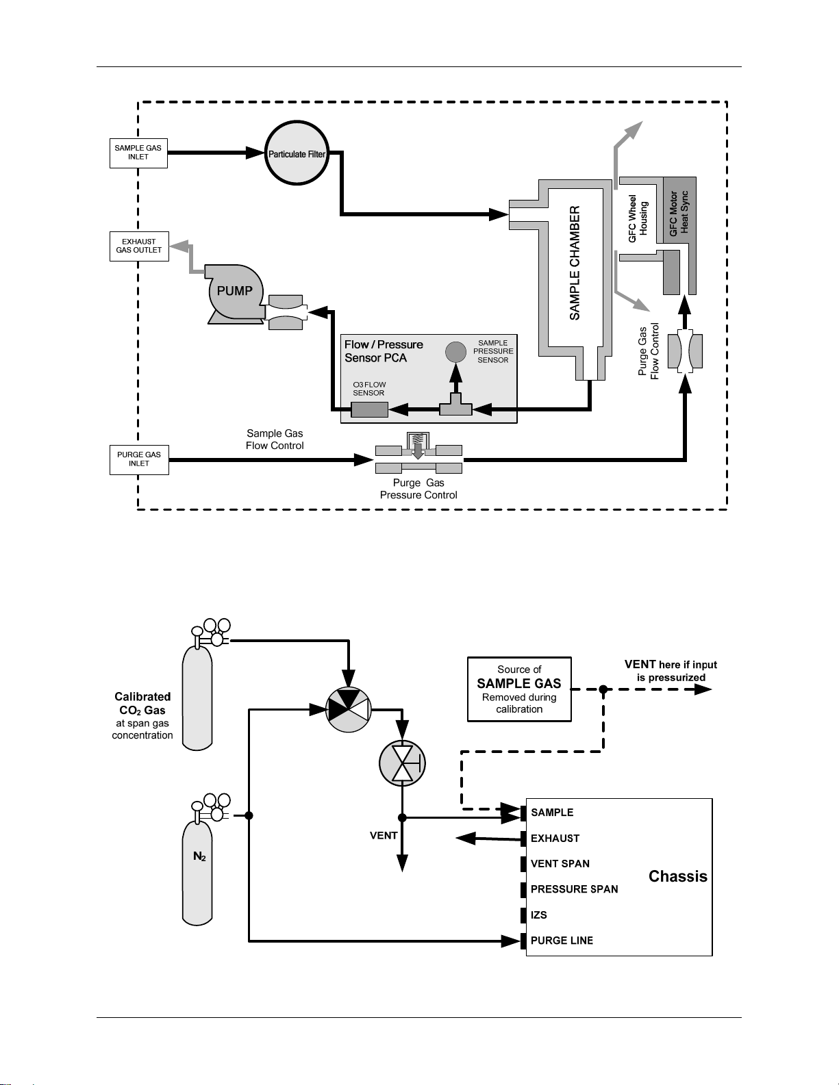
Teledyne API Model T360/T360M Operation Manual Getting Started
07272B DCN6552
Figure 3-11: Basic Internal Gas Flow
45
Page 48

Getting Started Teledyne API Model T360/T360M Operation Manual
07272B DCN6552
Figure 3-12: Pneumatic Connections–Basic Configuration–Using Bottled Span Gas
Figure 3-13: Pneumatic Connections–Basic Configuration–Using Gas Dilution Calibrator
1. Attach a sample inlet line to the sample inlet port. The SAMPLE input line
should not be more than 2 meters long.
NOTE
Ideally, the pressure of the sample gas should be at ambient pressure (0 psig).
Maximum pressure of sample gas should not exceed 1.5 in-Hg over ambient.
In applications where the sample gas is received from a pressurized manifold, a vent
must be placed as shown to equalize the sample gas with ambient atmospheric
pressure before it enters the analyzer. This vent line must be:
At least 0.2m long
No more than 2m long and vented outside the shelter or
immediate area surrounding the instrument.
2. Attach sources of zero air and span gas (see Figures 3-3 through 3-8
inclusive).
Span Gas is a gas specifically mixed to match the chemical composition
of the type of gas being measured at near full scale of the desired
measurement range.
In the case of CO2 measurements made with the Teledyne Instruments Model
T360 Analyzer it is recommended that you use a gas calibrated to have a CO
content equaling 80% of the range of compositions being measured.
2
46
Page 49

Teledyne API Model T360/T360M Operation Manual Getting Started
07272B DCN6552
EXAMPLE: If the application is to measure between 0 ppm and 500 ppm, an
appropriate Span Gas would be 400 ppm. If the application is to measure
between 0 ppm and 100 ppm, an appropriate Span Gas would be 80 ppm.
Span Gas can be purchased in pressurized canisters or created using
Dynamic Dilution Calibrator such as the Teledyne Instruments Model
T700 and a source of dried air scrubbed of CO
Zero Air
scrubbed of all components that might affect the analyzer’s readings.
is similar in chemical composition to the Earth’s atmosphere but
such as a bottle of N2.
2
In the case of CO2 measurements this means less than 0.1 ppm of CO2 and Water
Vapor (when dew point <-15˚C). Zero Air can be purchased in pressurized
canisters.
3. Attach an exhaust line to the exhaust outlet port.
The exhaust from the pump and vent lines should be vented to
atmospheric pressure using maximum of 10 meters of ¼” PTEF tubing.
CAUTION
Venting should be outside the shelter or immediate area surrounding
the instrument.
4. Attach a source of dried air scrubbed of CO2 to the purge inlet port.
NOTE
The minimum gas pressure of the source of purge air should be 7.5 psig.
If the source of the purge air is shared by a Teledyne Instruments T700 (e.g., Figure 3-13) the
minimum gas pressure should be 25 psig and should not exceed 35 psig.
5. Once the appropriate pneumatic connections have been made, check all
pneumatic fittings for leaks using a procedure similar to that defined in
Section 6.3.3.
47
Page 50

Getting Started Teledyne API Model T360/T360M Operation Manual
07272B DCN6552
3.6.2. Connections with Ambient Zero/Ambient Span Valve
Figure 3-14 and Figure 3-15 show the pneumatic connections for the ambient
zero and ambient span valve option (Option 50A).
Figure 3-14: Pneumatic Connections with Ambient Zero/Ambient Span Valves (OPT 50A)
Figure 3-15: Pneumatic Connections with Ambient Zero/Ambient Span Valves (Opt 50A) and
External Zero Air Scrubber
48
Page 51

Teledyne API Model T360/T360M Operation Manual Getting Started
07272B DCN6552
This valve option is intended for applications where zero air is supplied by a zero
air generator like a bottle of N
and span gas are being supplied by Gas Dilution
2
Calibrator like the Teledyne Instruments Model 700 or 702. Internal zero/span
and sample/cal valves control the flow of gas through the instrument, but because
the calibrator limits the flow of span gas no shutoff valve is required.
In order to ensure that span gas does not migrate backwards through the vent line
and alter the concentration of the span gas, a gas line not less than 2 meters in
length should be attached to the vent span outlet on the rear panel of the analyzer.
To prevent the buildup of back pressure, this vent line should not be greater than
10 meters in length.
Sample / Cal
Valve
NO
NC
COM
COM
NC
NO
Zero / Span
Valve
Sample Gas
Flow Control
Scrubber
External CO2
(Option 53 0nly)
O3 FLOW
SENSOR
Purge Gas
Pressure Control
SAMPLE
PRESSURE
SENSOR
Purge Gas
Flow Control
Figure 3-16: Internal Pneumatic Flow – Ambient Zero/Ambient Span
The following table describes the state of each valve during the analyzer’s
various operational modes.
Table 3-9: Ambient Zero/Ambient Span Valve Operating States
Mode Valve Condition
SAMPLE
(Normal State)
ZERO CAL
SPAN CAL
Sample/Cal Open to SAMPLE inlet
Zero/Span Open to IZS inlet
Sample/Cal Open to ZERO/SPAN valve
Zero/Span Open to IZS inlet
Sample/Cal Open to ZERO/SPAN valve
Zero/Span Open to PRESSURE SPAN inlet
The minimum span gas flow rate required for this option is 800 cm3/min.
49
Page 52

Getting Started Teledyne API Model T360/T360M Operation Manual
07272B DCN6552
The state of the zero/span valves can also be controlled:
Manually from the analyzer’s front panel by using the Signal I/O controls
located under the Diag Menu (Section 4.13),
By activating the instru
Remotely by usin
Remotely through the
ment’s AutoCal feature (Section 5.6),
g the external digital control inputs (Section 4.15.1.2)
RS-232/485 serial I/O ports (Section 4.15.2).
3.6.3. Connections with Ambient Zero/Pressurized Span Valve Option
Figure 3-17 and Figure 3-18 show the pneumatic connections for the ambient
zero and pressurized span valve option (Option 50B).
VENT
Figure 3-17: Pneumatic Connections with Ambient Zero/Pressurized Span Valves (OPT 50B)
50
Page 53

Teledyne API Model T360/T360M Operation Manual Getting Started
V
07272B DCN6552
Source of
ENT here if input
is pressurized
SAMPLE GAS
Removed during
calibration
Calibrated
CO
Gas
2
at span gas
concentration
VENT
SAMPLE
EXHAUST
VENT SPAN
Chassis
External
Zero Air
N
2
Scrubber
Figure 3-18: Pneumatic Connections with Ambient Zero/Pressurized Span Valves (Opt 50B) and
External Zero Air Scrubber
This option requires that both zero air and span gas be supplied from external
sources. It is specifically designed for applications where span gas will be
supplied from a pressurized bottle of calibrated CO
orifice, internal to the instrument ensures that the proper flow rate is maintained.
An internal vent line, isolated by a shutoff valve ensures that the gas pressure of
the span gas is reduced to ambient atmospheric pressure. Normally zero air
would be supplied from zero air modules such as a Teledyne Instruments Model
701.
In order to ensure that span gas does not migrate backwards through the vent line
and alter the concentration of the span gas, a gas line not less than 2 meters in
length should be attached to the vent span outlet on the rear panel of the analyzer.
To prevent the buildup of back pressure, this vent line should not be greater than
10 meters in length.
PRESSURE SPAN
IZS
PURGE LINE
gas. A critical flow control
2
51
Page 54

Getting Started Teledyne API Model T360/T360M Operation Manual
07272B DCN6552
Figure 3-19: Internal Pneumatic Flow – Ambient Zero/Pressurized Span Valves
The following table describes the state of each valve during the analyzer’s
various operational modes.
Table 3-10: Ambient Zero/Pressurized Span Valve Operating States
MODE VALVE CONDITION
SAMPLE
(Normal State)
ZERO CAL
SPAN CAL
Sample/Cal Open to SAMPLE inlet
Zero/Span Open to IZS inlet
Shutoff Valve Closed
Sample/Cal Open to ZERO/SPAN valve
Zero/Span Open to IZS inlet
Shutoff Valve Closed
Sample/Cal Open to ZERO/SPAN valve
Zero/Span Open to SHUTOFF valve
Shutoff Valve Open to PRESSURE SPAN Inlet
The minimum span gas flow rate required for this option is 800 cm3/min.
The state of the zero/span valves can also be controlled:
Manually from the analyzer’s front panel by using the SIGNAL I/O controls
located under the
DIAG Menu (Section 4.13.2)
52
By activating the instrument’s AutoCal feature (Section 5.6)
Remotely by usin
Remotely through the
g the external digital control inputs (Section 4.15.1.2)
RS-232/485 serial I/O ports (see Appendix A-6 for the
appropriate commands).
Page 55

Teledyne API Model T360/T360M Operation Manual Getting Started
07272B DCN6552
3.6.4. Pneumatic Connections in Multipoint Calibration Applications
Some applications may require multipoint calibration checks where span gas of
several different concentrations is needed. We recommend using highconcentration, certified, calibration gas supplied to the analyzer through a Gas
Dilution Calibrator such as a Teledyne Instruments Model T700. This type of
calibrator precisely mixes Span Gas and Zero Air to produce any concentration
level between 0 ppm and the concentration of the calibrated gas.
Figure 3-20 depicts the pneumatic set up in this sor
T360 CO
Analyzer with ambient zero/ambient span valve option installed (a
2
common configuration for this type of application).
t of application of a Model
Figure 3-20: Example of Pneumatic Set up for Multipoint Calibration
3.6.5. Setting the Internal Purge Air Pressure
In order to maintain proper purge air flow though the GFC wheel housing, a
manually adjustable pressure regulator is provided (see Figure 3-5). This
regulator includes two out
wheel. The other may be used to attach a pressure gauge.
To adjust the internal purge air pressure of the T360:
1. Turn off the instrument.
2. Remove the source of zero air attached to the purge line inlet port at the
back of the analyzer.
3. Remove the analyzer’s top cover.
53
put ports. One is used to supply purge air to the GFC
Page 56

Getting Started Teledyne API Model T360/T360M Operation Manual
07272B DCN6552
4. Remove the cap from the second, unused, output port on the pressure
regulator.
5. Attach a pressure gauge capable of measuring in the 5-10 psig range with
0.5 psig resolution to the port.
6. Turn the instrument on.
7. Make sure the zero air supply to the analyzer’s purge line inlet is supplying
gas at a stable pressure above 7.5 psig.
8. Adjust the T360’s pressure regulator until the attached gauge reads 7.5 psig.
9. Turn off the instrument.
10. Remove the source of zero air attached to the purge line inlet port at the
back of the analyzer.
11. Remove the pressure gauge and reattach the end cap removed in step 4
above.
12. Replace the analyzer’s top cover.
3.7. INITIAL OPERATION
If you are unfamiliar with the T360 principles of operation, we recommend that
you read Section 7. For information on navigating the analyzer’s software
menus, see the
The analyzer’s cover must be installed to ensure that the temperatures of the GFC wheel and
absorption cell assemblies are properly controlled.
menu trees described in Appendix A.
NOTE
3.7.1. Startup
After electrical and pneumatic connections are made, and initial functional check
is required. Turn on the instrument. The pump, exhaust fan and PMT cooler fan
should start immediately. The display will briefly show a logo splash screen at
the start of initialization.
The analyzer should automatically switch to Sample Mode after completing the
boot-up sequence and start monitoring CO
approximately one hour warm-up period before reliable gas measurements can be
taken. During the warm-up period, the front panel display may show messages in
the Parameters field.
gas. However, there is an
2
54
Page 57

Teledyne API Model T360/T360M Operation Manual Getting Started
07272B DCN6552
3.7.2. Warm Up
During the warm-up period various portions of the instrument’s front panel may
behave as indicated in Table 3-11.
Table 3-11: Front Panel Display During System Warm-Up
NAME COLOR BEHAVIOR SIGNIFICANCE
Displays current,
Conc field N/A
compensated CO2
Concentration
Displays current
Mode field N/A
mode, e.g.,
SAMPLE”
Param field N/A
Displays menu items
and messages.
STATUS LEDs
Sample Green On
Cal Yellow Off The instrument’s calibration is not enabled.
Fault Red Blinking
This is normal operation, but deemed inaccurate during the
warm-up period.
Instrument is in Sample mode but is still in the process of
warming up. (DAS holdoff period is active)
Refer to Table 3-12 for a list and descriptions of warning
messages.
Unit is operating in sample mode; front panel display is
being updated.
Flashes On/Off when adaptive filter is active
The analyzer is warming up and hence out of specification
for a fault-free reading. Various warning messages appear
in the Param field.
3.7.3. Warning Messages
Because internal temperatures and other conditions may be outside be specified
limits during the analyzer’s warm-up period, the software will suppress most
warning conditions for 30 minutes after power up. If warning messages persist
after the 30 minutes warm up period is over, investigate their cause using the
troubleshooting guidelines in Section 8 of this manual.
To view and clear w
TEST
deactivates warning
messages
If the warning message persists
after several attempts to clear it,
the message may indicate a
real problem and not an artifact
NOTE:
of the warm-up period
SAMPLE HVPS WARNING CO2 = 0.00
TEST CAL MSG CLR SETUP
SAMPLE
< TST TST > CAL
SAMPLE HVPS WARNING CO2 = 0.00
TEST CAL MSG CLR SETUP
Make sure warning messages are
arning messages, press:
RANGE=500.000 PPM
not due to real problems.
CO2 = 0.00
CLR SETUP
MSG
MSG
activates warning
messages.
<TST TST
Press
If more than one warning is active, the
next message will take its place
Once the last warning has been
cleared, the analyzer returns to
> keys replaced with
TEST
key
CLR
to clear the current
message.
SAMPLE
mode
55
Page 58

Getting Started Teledyne API Model T360/T360M Operation Manual
07272B DCN6552
Table 3-12 lists brief descriptions of the warning messages that may occur during
start up.
Table 3-12: Possible Warning Messages at Start-Up
MESSAGE MEANING
ANALOG CAL WARNING
BENCH TEMP WARNING
BOX TEMP WARNING
CANNOT DYN SPAN
CANNOT DYN ZERO
CONC ALRM1 WARNING
CONC ALRM2 WARNING
CONFIG INITIALIZED
DATA INITIALIZED
O2 CELL TEMP WARN
The instrument’s A/D circuitry or one of its analog outputs is not calibrated.
The optical bench Temperature is outside the specified limits.
Remote span calibration failed while the dynamic span feature was set to
turned on.
Remote zero calibration failed while the dynamic zero feature was set to
turned on.
Configuration was reset to factory defaults or was erased.
Concentration alarm 1 is enabled and the measured CO2 level is ≥ the set
point.
Concentration alarm 2 is enabled and the measured CO2 level is ≥ the set
point.
Configuration storage was reset to factory configuration or erased.
DAS data storage was erased.
O2 sensor cell temperature outside of warning limits.
PHOTO TEMP WARNING
REAR BOARD NOT DET
RELAY BOARD WARN
SAMPLE FLOW WARN
SAMPLE PRESS WARN
SAMPLE TEMP WARN
SOURCE WARNING
SYSTEM RESET
WHEEL TEMP WARNING
56
The temperature of the IR photometer is outside the specified limits.
The CPU is unable to communicate with the motherboard.
The firmware is unable to communicate with the relay board.
The flow rate of the sample gas is outside the specified limits.
Sample gas pressure outside of operational parameters.
The temperature of the sample gas is outside the specified limits.
The IR source may be faulty.
The computer was rebooted.
The Gas Filter Correlation wheel temperature is outside the specified limits.
Page 59

Teledyne API Model T360/T360M Operation Manual Getting Started
1
g
07272B DCN6552
3.7.4. Functional Checks
1. After the analyzer’s components has warmed up for at least 30 minutes,
verify that the software properly supports any hardware options that were
installed.
2. Check to make sure that the analyzer is functioning within allowable
operating parameters. Appendix C includes a list of test functions viewable
from the analyzer’s front panel as well as their expected values. These
functions are also useful tools for diagnosing performance problems with
your analyzer (Section11.1.2). The enclosed Final Test and Validation Data
sheet (part number 04307) lists these values before the instrument left the
factory.
To view the current values of these parameters press the following button
sequence on the analyzer’s front panel. Remember until the unit has completed
its warm up these parameters may not have stabilized.
SAMPLE RANGE = 500.000 PPM CO2 = XXX.X
< TST TST > CAL SETUP
RANGE
RANGE1
Toggle <TST TST> buttons
to scroll throu
Only appears instrument is set
for DUAL or AUTO reporting
range modes.
2
Only appears if O2 Sens or
Option is installed.
h list of
RANGE2
O2 RANGE
STABIL
MEAS
MR RATIO
PRES
SAMP FL
SAMP TEMP
BENCH TEMP
WHEEL TEMP
BOX TEMP
PHT DRIVE
SLOPE
OFFSET
RE F
TEST
TIME
1
1
2
3. If your network is running a dynamic host configuration protocol (DHCP)
software package, the Ethernet feature will automatically configure its
interface with your LAN. (See Section 4.11.6.1). This configuration is useful
for quickly ge
tting an instru
ment up and running on a network. However, for
permanent Ethernet connections, a static IP address should be used. (See
Section 4.11.6.2).
57
Page 60

Getting Started Teledyne API Model T360/T360M Operation Manual
c
07272B DCN6552
3.8. INITIAL CALIBRATION PROCEDURE
The next task is to calibrate the analyzer.
To perform the following calibration you must have sources for zero air and span
gas available for input into the sample port on the back of the analyzer. See
Section 3.6 for instructions for connecting these gas sources.
Press this button to set
the an alyzer for SNGL
DUAL or AUTO ranges
To change the value of the
reportin g range span, enter the
number by pr essing t he key under
each digit until the expected value
appears .
While it is possible to
perform
this procedure with any range setting we
recommend that you perform this initial checkout using the 500 ppm range.
The following procedure assumes that the instrument does not have any of
the available Zero/Span Valve Options installed. See Section 5.4 for
instructions for calibrating instrumen
1. Set the Analog Output Range:
SAMPLE RANGE = 500.000 PPM CO2 =X. XXX
< TST TST > CAL SETUP
SETUP X. X
CFG DAS RNGE PASS CLK MORE EXI T
SETUP X. X RANGE CONTROL MENU
MODE
SET UNIT EXIT
SETUP X. X RANGE : 500.00 0 CON C
0 0 5 0 0 .0 ENTR EXIT
SETUP X. X RANG E: 500.000 Con
0 0 0 5 0 .0 ENTR EXI T
ts with Z/S valve options.
Press this button to select the
concent ration units o f me asur e:
PPB, P PM , UG M, MGM
EXIT ignore s the new setting and
returns to the RANGE CONTROL
ENTR accepts th e new setti ng and
RANGE CONTROL MENU.
MENU.
r eturn s to th e
58
Page 61
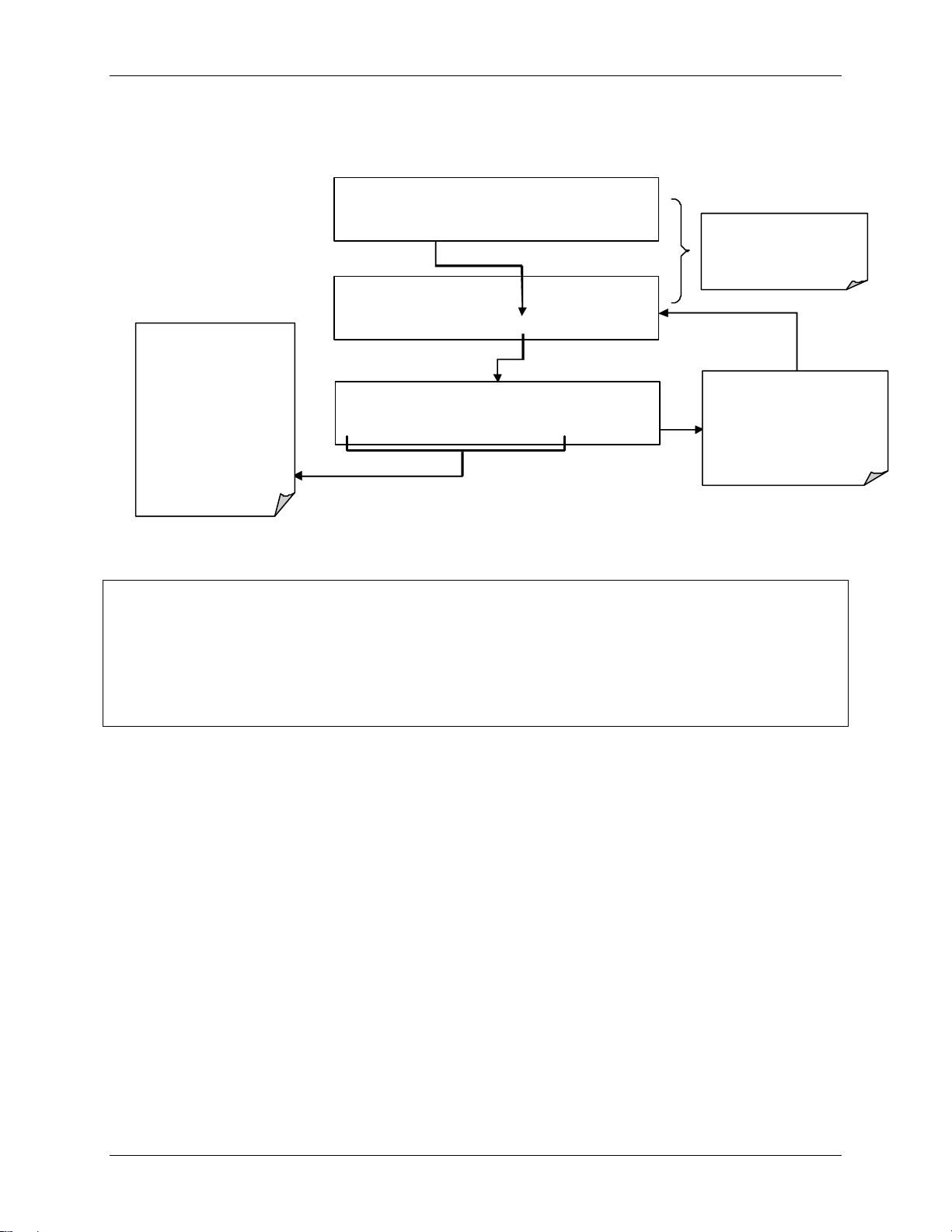
Teledyne API Model T360/T360M Operation Manual Getting Started
07272B DCN6552
2. Set the expected CO2 span gas concentration
The CO2 span
concent ration valu es
automatically default to
400.0 Conc.
To change this value to
the actual concentrat ion of
th e span gas, en ter the
number by pressing the
button under each digit
until the expected value
appears.
SAMPLE* RANGE = 500.000 PPM CO2 =X.XXX
< TST TST > CAL SETUP
M-P CAL RANGE = 500.000 PPM CO2 =X.XXX
< TST TST > ZERO CONC EXIT
M-P CAL CO2 SPAN CONC: 400.000 Conc
0 0 0 4 5 .0 ENTR EX IT
This sequence causes the
analyzer to pr omp t for the
expe cte d CO
co ncent ratio n.
EXIT ignores the new setting
and retu rn s to the p revious
ENTR accepts the new setting
and returns to the
previous display..
span
2
display.
NOTE
For this Initial Calibration it is important to independently verify the precise CO2 Concentration
Value of the SPAN gas.
If the source of the Span Gas is from a Calibrated Bottle, use the exact concentration value
printed on the bottle.
59
Page 62

Getting Started Teledyne API Model T360/T360M Operation Manual
A
A
07272B DCN6552
3. Perform the Zero/Span Calibration Procedure
SAMPLE* RANGE = 500.000 PPM CO2 =XXX.X
< TS T TST > CAL SETUP
SAMPLE STABI L= XXX.X P PM CO2 =XXX.X
< TST TST > CAL SETUP
Allow zero gas to enter the sample port at the
M-P CAL STAB IL= XXX. X P PM CO2 =XXX.X
< TST TST > CAL SETUP
M-P CAL STAB IL= XXX. X P PM CO2 =XXX.X
< TST TST > ZERO CONC EXIT
M-P CAL STABIL=XXX.X PPM CO2 =XXX.X
< TST TST > ENT R CONC EXIT
CTION:
rear of the instrument.
Set the Display to show the
STABIL test function.
Th is fu nct ion calculates th e
stability of the CO
m easurement
Wait until STABIL
falls below 1.0 ppm.
This may take several
minutes.
Press EN TR to changes the
OFFSET & SLO PE valu es for th e
Press EX IT to leave the calibration
m easu remen ts.
CO
2
unchanged and return to the
previ ous menu.
x
The SPAN button now
appears during the
transition from zero to
span..
If either the ZERO or
SPAN buttons fail to
appear see Section 11
for tr ouble shooting t ips.
Allow span gas to enter the sample port at the
M-P CAL STABI L= XX X.X PPM CO2 =XXX.X
< TST TST > SPAN CONC EXIT
M-P CAL RANGE = 500.000 PPM CO2 =XXX.X
< TST TST > ENTR SPAN CONC EXIT
M-P CAL RANGE = 500.000 PPM CO2 =XXX.X
< TST TST > ENTR CONC EXIT
CTION:
rear of the instrument.
The value of
STABIL may j ump
significantly.
Wait until it falls back
below 1.0 pp m
This may take several
minutes.
Press ENTR to change the
OFF SET & SLOPE values for the
CO
m easu remen ts.
2
Press EX IT to leave the calibration
unchanged and return to the
previ ous menu.
EXIT returns to the main
SAMPLE display
60
Page 63

Teledyne API Model T360/T360M Operation Manual Getting Started
07272B DCN6552
3.8.1. Initial O2 Sensor Calibration Procedure
If your instrument includes the O2 sensor option, that should be calibrated as well.
3.8.1.1. O2 SENSOR CALIBRATION SETUP
The pneumatic connections for calibrating are as follows:
Figure 3-21: O2 Sensor Calibration Set Up
O2 SENSOR ZERO GAS: Teledyne Instruments’ recommends using pure N2
when calibration the zero point of your O
O
SENSOR SPAN GAS: Teledyne Instruments’ recommends using 21% O2 in
2
when calibration the span point of your O2 sensor option.
N
2
sensor option.
2
61
Page 64

Getting Started Teledyne API Model T360/T360M Operation Manual
07272B DCN6552
Figure 3-22: Internal Pneumatics with O2 Sensor Option 65
62
Page 65

Teledyne API Model T360/T360M Operation Manual Getting Started
07272B DCN6552
3.8.1.2. O2 CALIBRATION METHOD
STEP 1 – SET O2 SPAN GAS CONCENTRATION :
Set the expected O2 span gas concentration.
This should be equal to the percent concentration of the O
selected reporting range (default factory setting = 20.8%; the approximate O
content of ambient air).
SAMPLE RANGE = 500.000 PPM CO2 =XXX.X
< TST TST > CAL SETUP
SAMPLE GAS TO CAL:CO2
CO2 O2 ENTR EXIT
SAMPLE GAS TO CAL:O2
NOX O2 ENTR EXIT
The O2 span concentration value automatically defaults to
If this is not the the concentration of the span gas being
used, toggle these buttons to set the correct concentration
of the O
20.8 %.
calibration gases.
2
M-P CAL A1:NXCNC1 =100PPM NOX=X.XXX
<TST TST> ZERO SPAN CONC EXIT
M-P CAL O2 SPAN CONC:20.8%
0 2 0 .8 0 ENTR EXIT
span gas of the
2
EXIT ignores the new
setting and returns to
the previous display.
ENTR accepts the new
setting and returns to
the previous menu.
2
63
Page 66

Getting Started Teledyne API Model T360/T360M Operation Manual
07272B DCN6552
STEP 2 – ACTIVATE O2 SENSOR STABILITY FUNCTION
To change the stability test function from NOx concentration to the O2 sensor
output, press:
NOTE
Use the same procedure to reset the STB test function to CO2 when the O2 calibration procedure
is complete.
64
Page 67

Teledyne API Model T360/T360M Operation Manual Getting Started
07272B DCN6552
STEP 4 – O2 Zero/Span Calibration perform by pressing:
The analyzer is now ready for operation.
65
Page 68

Getting Started Teledyne API Model T360/T360M Operation Manual
07272B DCN6552
NOTE
Once you have completed the preceding set-up procedures, please fill out the Quality
Questionnaire that was shipped with your unit and return it to Teledyne Instruments.
This information is vital to our efforts in continuously improving our service and our products.
THANK YOU.
66
Page 69

07272B DCN6552
4. OPERATING INSTRUCTIONS
To assist in navigating the analyzer’s software, a series of menu trees can be
found in Appendix A-1 of this manual.
NOTES
The flow charts appearing in this contain typical representations of the analyzer’s display during the
various operations being described. These representations may differ slightly from the actual display of
your instrument.
The ENTR button may disappear if you select a setting that is invalid or out of the allowable range for that
parameter, such as trying to set the 24-hour clock to 25:00:00. Once you adjust the setting to an
allowable value, the ENTR button will re-appear.
4.1. OVERVIEW OF OPERATING MODES
The T360 software has a variety of operating modes. Most commonly, the
analyzer will be operating in SAMPLE mode. In this mode, a continuous readout of the CO
analog voltage from rear panel terminals, calibrations can be performed, and
TEST functions and WARNING messages can be examined.
concentration is displayed on the front panel and output as an
2
The second most important operating mode is SETUP mode. This mode is used
for performing certain configuration operations, such as for the DAS system, the
reporting ranges, or the serial (RS-232/RS-485/Ethernet) communication
channels. The SET UP mode is also used for performing various diagnostic tests
during troubleshooting.
Figure 4-1: Front Panel Display
67
Page 70

Operating Instructions Teledyne API Model T360/T360M Operation Manual
07272B DCN6552
The Mode field of the front panel display indicates to the user which operating
mode the unit is currently running.
Besides SAMPLE and SETUP, other modes the analyzer can be operated in are:
Table 4-1: Analyzer Operating Modes
MODE MEANING
DIAG
M-P CAL This is the basic, multi-point calibration mode of the instrument and is activated by pressing
SAMPLE
SAMPLE A Indicates that unit is in SAMPLE Mode and AUTOCAL feature is activated.
SETUP
SPAN CAL A
SPAN CAL M
SPAN CAL R Unit is performing span cal procedure initiated remotely via the RS-232, RS-4485 or digital i/o
ZERO CAL A
ZERO CAL M
ZERO CAL R Unit is performing zero cal procedure initiated remotely via the RS-232, RS-4485 or digital I/O
One of the analyzer’s diagnostic modes is being utilized (See Section 4.13).
the CAL button.
Sampling normally, flashing indicates adaptive filter is on.
SETUP mode is being used to configure the analyzer (CO
process).
Unit is performing span cal procedure initiated automatically by the analyzer’s AUTOCAL
feature.
Unit is performing span cal procedure initiated manually by the user.
control inputs.
Unit is performing zero cal procedure initiated automatically by the analyzer’s AUTOCAL
feature.
Unit is performing zero cal procedure initiated manually by the user.
control inputs.
sampling will continue during this
2
Finally, the various CAL modes allow calibration of the analyzer. Because of its
importance, this mode is described separately in Section 5.
4.2. SAMPLE MODE
This is the analyzer’s standard operating mode. In this mode the instrument is
analyzing the gas in the sample chamber, calculating CO
reporting this information to the user via the front panel display, the analog
outputs and, if set up properly, the RS-232/485/Ethernet ports.
NOTE
A value of “XXXX” displayed in the CO2 Concentration field means that the M/R ratio is invalid
because CO2 REF is either too high (> 4950 mVDC) or too low (< 1250 VDC).
concentration and
2
68
Page 71

Teledyne API Model T360/T360M Operation Manual Operating Instructions
07272B DCN6552
4.2.1. Test Functions
Test functions are shown on the front panel display while the analyzer is in
SAMPLE mode. They provide information about the present operating status of
the instrument and can be used troubleshooting and can be recorded in one of the
DAS channels (Section 4.7) for data analysis. To view, press <TST or TST>.
Table 4-2: Test Functions Defined
PARAMETER DISPLAY UNITS MEANING
Range
O2 Range
Stability
CO2 Measure
CO2 Reference
Measurement /
Reference Ratio MR Ratio
Sample Pressure
Sample Flow
Sample
Temperature
Bench
Temperature
Wheel
Temperature
Box Temperature
O2 Cell
Temperature
2
Photo-detector
Temp. Control
Voltage
Slope
Offset
O2 Sensor Slope 2
O2 Sensor Offset 2
Test channel
output signal
Current Time
1
Only appears when the instrument’s reporting range mode is set for DUAL or AUTO
2
Only appears when the optional O2 sensor is installed.
RANGE
RANGE11
RANGE2
1
O2 RANGE
STABIL
MEAS
REF
PRES
SAMPLE FL
SAMP TEMP
BENCH TEMP
WHEEL TEMP
BOX TEMP
O2 CELL
2
TEMP
PHT DRIVE
SLOPE
OFFSET
O2 SLOPE
O2 OFFSET
TEST
TIME
PPB, PPM,
UGM, MGM
The full scale limit at which the reporting range of the analyzer is
currently set. THIS IS NOT the Physical Range of the instrument.
See Section 4.8 for more information.
% The range setting for the O2 Sensor
PPB, PPM
UGM, MGM
MV
MV
Standard deviation of CO2 concentration readings. Data points are
recorded every ten seconds using the last 25 data points.
The demodulated, peak IR detector output during the measure
portion of the GFC Wheel cycle.
The demodulated, peak IR detector output during the reference
portion of the GFC wheel cycle.
The result of CO2 MEAS divided by CO2 REF. This ratio is the
-
primary value used to compute CO
concentration. The value
2
displayed is not linearized.
In-Hg-A
The absolute pressure of the Sample gas as measured by a
pressure sensor located inside the sample chamber.
Sample mass flow rate. This is computed from the differential
cc/min
between the pressures measured up-stream and down-stream of the
sample critical flow orifice pressures.
C
C
C
C
C
mV
The temperature of the gas inside the sample chamber.
Optical bench temperature.
Filter wheel temperature.
The temperature inside the analyzer chassis.
sensor cell temperature.
O
2
The drive voltage being supplied to the thermoelectric coolers of the
IR photo-detector by the sync/demod Board.
The sensitivity of the instrument as calculated during the last
-
calibration activity. The SLOPE parameter is used to set the span
calibration point of the analyzer.
The overall offset of the instrument as calculated during the last
-
calibration activity. The OFFSET parameter is used to set the zero
point of the analyzer response.
- O2 slope, computed during zero/span calibration.
- O2 offset, computed during zero/span calibration.
mV, mA
-
Displays the signal level of the TEST analog output channel. Only
appears when the TEST channel has been activated.
The current time. This is used to create a time stamp on DAS
readings, and by the AUTOCAL feature to trigger calibration events.
69
Page 72

Operating Instructions Teledyne API Model T360/T360M Operation Manual
1
g
07272B DCN6552
To view the TEST Functions press:
SAMPLE RANGE = 500.000 PPM CO2 = XXX.X
< TST TST > CAL SETUP
Toggle <TST TST> buttons
to scroll throu
Only appears instrument is set
h list of
for DUAL or AUTO reporting
range modes.
2
Only appears if O2 Sensor
Option is installed.
RANGE
RANGE1
RANGE2
1
1
O2 RANGE
STABIL
MEAS
REF
MR RATIO
PRES
SAMP FL
SAMP TEMP
BENCH TEMP
WHEEL TEMP
BOX TEMP
PHT DRIVE
SLOPE
OFFSET
TEST
TIME
Refer to
Table 6-2 for
definitions of
these test
functions.
Figure 4-2: Viewing TEST Functions
NOTE
A value of “XXXX” displayed for any of the TEST functions indicates an out-of-range reading or
the analyzer’s inability to calculate it.
All pressure measurements are represented in terms of absolute pressure. Absolute, atmospheric
pressure is 29.92 in-Hg-A at sea level. It decreases about 1 in-Hg per 300 m gain in altitude. A
variety of factors such as air conditioning and passing storms can cause changes in the absolute
atmospheric pressure.
4.2.2. Warning Messages
The most common instrument failures will be reported as a warning on the
analyzer’s front panel and through the COM ports. Section 8.1.1 explains how to
use these messages to troubleshoot pr
and clear warn
ing messages.
Table 4-3 lists warning messages for the current version of software.
oblems. Section 3.7.3 shows how to view
70
Page 73

Teledyne API Model T360/T360M Operation Manual Operating Instructions
07272B DCN6552
Table 4-3: List of Warning Messages
MESSAGE MEANING
ANALOG CAL WARNING
BENCH TEMP WARNING
BOX TEMP WARNING
CANNOT DYN SPAN
CANNOT DYN ZERO
CONC ALRM1 WARNING
CONC ALRM2 WARNING
CONFIG INITIALIZED
DATA INITIALIZED
O2 CELL TEMP WARN
PHOTO TEMP WARNING
REAR BOARD NOT DET
RELAY BOARD WARN
SAMPLE FLOW WARN
The instrument’s A/D circuitry or one of its analog outputs is not calibrated.
The Temperature of the optical bench is outside the specified limits.
Remote span calibration failed while the dynamic span feature was set to turned on
Remote zero calibration failed while the dynamic zero feature was set to turned on
Configuration was reset to factory defaults or was erased.
Concentration alarm 1 is enabled and the measured CO2 level is ≥ the set point.
Concentration alarm 2 is enabled and the measured CO2 level is ≥ the set point.
Configuration storage was reset to factory configuration or erased.
DAS data storage was erased.
O2 sensor cell temperature outside of warning limits.
The temperature of the IR photometer is outside the specified limits.
The CPU is unable to communicate with the motherboard.
The firmware is unable to communicate with the relay board.
The flow rate of the sample gas is outside the specified limits.
SAMPLE PRESS WARN
SAMPLE TEMP WARN
SOURCE WARNING
SYSTEM RESET
WHEEL TEMP WARNING
Sample gas pressure outside of operational parameters.
The temperature of the sample gas is outside the specified limits.
The IR source may be faulty.
The computer was rebooted.
The Gas Filter Correlation wheel temperature is outside the specified limits.
71
Page 74

Operating Instructions Teledyne API Model T360/T360M Operation Manual
07272B DCN6552
To view and clear warning messages:
TEST deactivates warning
messages
SAMPLE SYSTEM RE SET CO2 = 0.00
TEST CAL MSG CLR SETUP
SAMPLE RANGE=500.000 PPM CO2 = 0.00
< TST TST > CAL MSG CLR SETUP
SA MPLE SYSTEM RESET CO2 = 0.00
If the warning message persists
after several attempts to clear it,
the message may indicate a
real problem and not an artifact
NOTE:
of the warm-up period
T EST CAL MSG CLR SETUP
Figure 4-3: Viewing and Clearing T360 WARNING Messages
4.3. CALIBRATION MODE
Pressing the CAL button switches the T360 into multi-point calibration mode. In
this mode, the user can calibrate the instrument or check the instruments
calibration with the use of calibrated zero or span gases.
If the instrument includes either the zero/span valve option or IZS option, the
display will also include CALZ and CALS buttons. Pressing either of these
buttons also puts the instrument into multipoint calibration mode.
MSG displays warning messages.
Press CLR to clear the current
message.
If more than one warning is active, the
next message will take its place
Once the l ast warning has been
cleared, the analyzer returns to
SAMPLE m ode
72
CALZ is used to initiate a calibration of the zero point.
CALS is used to calibrate the span point of the analyzer. It is recommended
that this span calibration is performed at 90% of full scale of the analyzer’s
currently selected reporting range.
Because of their critical importance and complexity, calibration operations are
described in detail in Section 5 of this manual. For more information concerning
the valve options, see Section 3.6.
Page 75

Teledyne API Model T360/T360M Operation Manual Operating Instructions
07272B DCN6552
4.4. SETUP MODE
The SETUP mode contains a variety of choices that are used to configure the
analyzer’s hardware and software features, perform diagnostic procedures, gather
information on the instruments performance and configure or access data from
the internal data acquisition system (DAS). For a visual representation of the
software menu trees, refer to Appendix A. The areas access under the Setup mode
are presented in Table 4-4 and Table 4-5.
Table 4-4: Primary Setup Mode Features and Functions
MODE OR
FEATURE
Analyzer
Configuration
Auto Cal Feature
Internal Data
Acquisition (DAS)
Analog Output
Reporting Range
Configuration
Calibration
Password Security
Internal Clock
Configuration
Advanced SETUP
Features
TOUCHSCREEN
BUTTON
CFG
ACAL
DAS
RNGE
PASS
CLK
MORE
Lists key hardware and software configuration information
Used to set up and operate the AutoCal feature.
Only appears if the analyzer has one of the internal valve
options installed
Used to set up the DAS system and view recorded data
Used to configure the output signals generated by the
instruments Analog outputs.
Turns the calibration password feature ON/OFF
Used to Set or adjust the instrument’s internal clock
This button accesses the instruments secondary setup menu
Table 4-5: Secondary Setup Mode Features and Functions
MODE OR FEATURE
External Communication
Channel Configuration
System Status Variables
System Diagnostic Features
CO2 Concentration Alarms
TOUCHSCREEN
BUTTON
COMM
VARS
DIAG
ALRM
Used to set up and operate the analyzer’s various
external I/O channels including RS-232; RS-485,
modem communication and/or Ethernet access.
Used to view various variables related to the
instruments current operational status
Used to access a variety of functions that are used to
configure, test or diagnose problems with a variety of
the analyzer’s basic systems
Used to activate the analyzer’s two gas concentration
status alarms and set the alarm limits
DESCRIPTION
DESCRIPTION
NOTE
Press ENTR to accept/apply changes made to a variable.
Press EXIT to ignore the change(s). (There will be an audible alert that the change has been lost).
73
Page 76
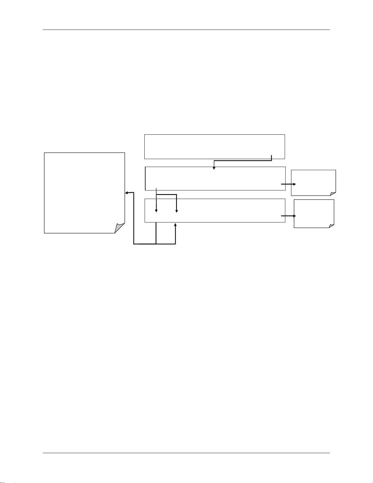
Operating Instructions Teledyne API Model T360/T360M Operation Manual
1
07272B DCN6552
4.5. SETUP CFG: VIEWING THE ANALYZER’S
CONFIGURATION INFORMATION
Pressing the CFG button displays the instrument configuration information. This
display lists the analyzer model, serial number, firmware revision, software
library revision, CPU type and other information. Use this information to
identify the software and hardware when contacting Technical Support. Special
instrument or software features or installed options may also be listed here.
Pres s NEXT and PRE V to sc roll thr oug h the
following list of Configuration information:
MO DEL NAME
P ART NUMBER
S ERIAL NUMBER
SOFTWARE REVISION
LIBRARY REVISION
iCHIP SOFTWARE REVISION
HESSEN PROTOCOL REVISI ON
ACT IVE SPEC IAL SOF TWARE
CP U TYPE
DATE FACTORY CONFIGURATION
OPTIONS
SAVED
1
1
1
SAMPLE* RANGE = 500.000 PPB CO2 =X.XXX
< TST TST > CAL SETUP
SAMPLE PRIMARY SETUP MENU
CFG DAS RNGE PASS CLK MORE EXIT
SAMPLE T360 CO2 ANALYZER
NEXT PREV EXIT
Press EXIT at any
time to return to the
SAMPLE display
Press EXIT at
any time to
return to SETUP
menu
Only appears if r elev ant op ti on of Feature is active.
4.6. SETUP ACAL: AUTOMATIC CALIBRATION
Instruments with one of the internal valve options installed can be set to
automatically run calibration procedures and calibration checks. These automatic
procedures are programmed using the submenus and functions found under the
ACAL menu.
A menu tree showing the ACAL menu’s entire structure can be found in
Appendix A-1 of this manual.
Instructions for using the ACAL feature are located in Section 5.6 of this manual.
74
Page 77

Teledyne API Model T360/T360M Operation Manual Operating Instructions
07272B DCN6552
4.7. SETUP DAS: USING THE DATA ACQUISITION
SYSTEM (DAS)
The T360 analyzer contains a flexible and powerful, internal data acquisition
system (DAS) that enables the analyzer to store concentration and calibration data
as well as a host of diagnostic parameters. The DAS of the T360 can storeseveral
months worth of measurements, depending on how it is configured. The data are
stored in non-volatile memory and are retained even when the instrument is
powered off. Data are stored in plain text format for easy retrieval and use in
common data analysis programs (such as spreadsheet-type programs).
The DAS is designed to be flexible, users have full control over the type, length
and reporting time of the data. The DAS permits users to access stored data
through the instrument’s front panel or its communication ports. Using
APICOM, data can even be retrieved automatically to a remote computer for
further processing.
The principal use of the DAS is logging data for trend analysis and predictive
diagnostics, which can assist in identifying possible problems before they affect
the functionality of the analyzer. The secondary use is for data analysis,
documentation and archival in electronic format.
To support the DAS functionality, Teledyne API offers APICOM, a program that
provides a visual interface for remote or local setup, configuration and data
retrieval of the DAS (Section 4.15.2.8). The APICOM manual, which is included
with the program
, contains a more detailed description of the DAS structure and
configuration.
The T360 is configured with a basic DAS configuration, which is enabled by
default. New data channels are also enabled by default but each channel may be
turned off for later or occasional use. Note that DAS operation is suspended
while its configuration is edited through the front panel. To prevent such data
loss, it is recommended to use the APICOM graphical user interface for DAS
changes.
The green SAMPLE LED on the instrument front panel, which indicates the
analyzer status, also indicates certain aspects of the DAS status:
Table 4-6: Secondary Setup Mode Features and Functions
LED STATE DAS Status
OFF System is in calibration mode. Data logging can be enabled or disabled for this mode.
Calibration data are typically stored at the end of calibration periods, concentration data are
typically not sampled, diagnostic data should be collected.
BLINKING Instrument is in hold-off mode, a short period after the system exits calibrations. DAS
channels can be enabled or disabled for this period. Concentration data are typically disabled
whereas diagnostic should be collected.
ON
Sampling normally.
The DAS can be disabled only by disabling or deleting its individual data
channels.
75
Page 78

Operating Instructions Teledyne API Model T360/T360M Operation Manual
07272B DCN6552
4.7.1. DAS Structure
The DAS is designed around the feature of a “record”. A record is a single data
point of one parameter, stored in one (or more) data channels and generated by
one of several triggering event. The entire DAS configuration is stored in a
script, which can be edited from the front panel or downloaded, edited and
uploaded to the instrument in form of a string of plain-text lines through the
communication ports.
DAS data are defined by the PARAMETER type and are stored through different
triggering EVENTS in data CHANNELS, which relate triggering events to data
parameters and define certain operational functions related to the recording and
reporting of the data.
4.7.1.1. DAS CHANNELS
The key to the flexibility of the DAS is its ability to store a large number of
combinations of triggering events and data parameters in the form of data
channels. Users may create up to 20 data channels; each channel can contain one
or more parameters. For each channel one triggering event is selected and up to
50 data parameters, which can be the same or different between channels. Each
data channel has several properties that define the structure of the channel and
allow the user to make operational decisions regarding the channel (Table 4-7).
Table 4-7: DAS Data Channel Properties
PROPERTY DESCRIPTION DEFAULT SETTING RANGE
NAME
TRIGGERIN
G EVENT
NUMBER &
PARAMET
ER LIST
STARTING
DATE
SAMPLE
PERIOD
REPORT
PERIOD
NUMBER
OF
RECORDS
RS-232
REPORT
CHANNEL
ENABLED
The name of the data channel.
The event that triggers the data channel to measure and
store its data parameters. See APPENDIX A-5 for a list
of available triggering events.
A user-configurable list of data types to be recorded in
any given channel. See APPENDIX A-5 for a list of
available parameters
The starting date when a channel starts collecting data
The amount of time between each data point that is
averaged into one mean reported every REPORT
PERIOD.
The amount of time between each channel data point.
The number of reports that will be stored in the data file.
Once the specified limit has been exceeded, the oldest
data are over-written to make space for new data.
Enables the analyzer to automatically report channel
values to the RS-232 ports.
Enables or disables the channel. Provides a convenient
means to temporarily disable a data channel.
“NONE” Up to 6 letters and digits
(more with APICOM,
but only the first six are
displayed on the front
panel).
ATIMER See Appendix A-5 For a
complete list.
1 – DETMES See Appendix A-5 For a
complete list.
01-JAN-03 Any actual date in the
past or future.
000:01:00 000:00:01 to 366:23:59
(Days:Hours:Minutes)
000:01:00
100 1 to 1 million, limited by
OFF
ON
000:00:01 to
366:23:59
(Days:Hours:Minutes)
available storage space.
OFF or ON
OFF or ON
76
Page 79

Teledyne API Model T360/T360M Operation Manual Operating Instructions
07272B DCN6552
PROPERTY DESCRIPTION DEFAULT SETTING RANGE
CAL HOLD
OFF
Disables sampling of data parameters while instrument is
in calibration mode.
When enabled here – there is also a length of the DAS
HOLD OFF after calibration mode, which is set in the
VARS menu.
OFF
OFF or ON
(Section 4.7.2.13)
4.7.1.2. DAS PARAMETERS
Data parameters are types of data that may be measured and stored by the DAS.
For each Teledyne Instruments analyzer model, the list of available data
parameters is different, fully defined and not customizable. Appendix A-5 lists
firmware specific data parameters for the analyzer. DAS parameters include
things like CO
placed around the analyzer, pressures and flows of the pneumatic subsystem and
other diagnostic measurements as well as calibration data such as slope and
offset.
Most data parameters have associated measurement units, such as mV, ppb,
cm³/min, etc., although some parameters have no units. With the exception of
concentration readings, none of these units of measure can be changed. To
change the units of measure for concentration readings see Section 4.8.6.
concentration measurements, temperatures of the various heaters
2
Note
DAS does not keep track of the unit of each concentration value, and DAS data files may contain
concentrations in multiple units if the unit was changed during data acquisition.
Each data parameter has user-configurable functions that define how the data are
recorded:
Table 4-8: DAS Data Parameter Functions
FUNCTION EFFECT
PARAMETER
SAMPLE MODE
PRECISION
STORE NUM.
SAMPLES
Instrument-specific parameter name.
INST: Records instantaneous reading.
AVG: Records average reading during reporting interval.
MIN: Records minimum (instantaneous) reading during reporting interval.
MAX: Records maximum (instantaneous) reading during reporting interval.
SDEV: Records the standard deviation of the data points recorded during the reporting interval.
Decimal precision of parameter value (0-4).
OFF: stores only the average (default).
ON: stores the average and the number of samples in each average for a parameter. This
property is only useful when the AVG sample mode is used. Note that the number of samples
is the same for all parameters in one channel and needs to be specified only for one of the
parameters in that channel.
Users can specify up to 50 parameters per data channel (the T360 provides about
30 parameters). However, the number of parameters and channels is ultimately
limited by available memory.
77
Page 80

Operating Instructions Teledyne API Model T360/T360M Operation Manual
07272B DCN6552
4.7.1.3. DAS TRIGGERING EVENTS
Triggering events define when and how the DAS records a measurement of any
given data channel. Triggering events are firmware-specific and a complete list
of Triggers for this model analyzer can be found in Appendix A-5. The most
commonly used triggering events are:
ATIMER: Sampling at regular intervals specified by an automatic timer. Most
trending information is usually stored at such regular intervals, which can be
instantaneous or averaged.
EXITZR, EXITSP, SLPCHG (exit zero, exit span, slope change): Sampling at
the end of (irregularly occurring) calibrations or when the response slope
changes. These triggering events create instantaneous data points, e.g., for
the new slope and offset (concentration response) values at the end of a
calibration. Zero and slope values are valuable to monitor response drift and
to document when the instrument was calibrated.
WARNINGS: Some data may be useful when stored if one of several
warning messages appears such as
warning) or
shooting by monitoring when a particular warning occurred.
PPRESW (purge pressure warning). This is helpful for trouble-
WTEMPW (GFC wheel temperature
4.7.2. Default DAS Channels
A set of default Data Channels has been included in the analyzer’s software for
logging CO
channels include but are not limited to:
CONC: Samples CO
every hour with a time and date stamp. Readings during calibration and
calibration hold off are not included in the data. By default, the last 800 hourly
averages are stored.
PNUMTC: Collects sample flow and sample pressure data at five minute
intervals and stores an average once a day with a time and date stamp. This data
is useful for monitoring the condition of the pump and critical flow orifice
(sample flow) and the sample filter (clogging indicated by a drop in sample
pressure) over time to predict when maintenance will be required. The last 360
daily averages (about 1 year) are stored.
CALDAT: Logs new slope and offset every time a zero or span calibration is
performed. This Data Channel also records the instrument readings just prior to
performing a calibration. This information is useful for performing predictive
diagnostics as part of a regular maintenance schedule (see Section 8.1).
STBZRO: L
detector of the most recent measure phase and the measure/reference ratio every
time the instrument exits the zero calibration mode. Data from the last 200 zero
calibrations is stored. A time and date stamp is recorded for every data point
logged. This information is useful for performing predictive diagnostics as part
of a regular maintenance schedule (see Section 8.1).
concentration and certain predictive diagnostic data. These default
2
ogs the concentration stability, the electronic output of the IR
concentration at one minute intervals and stores an average
2
78
STBSPN: Logs the electronic output
of the IR
detector of the most recent
measure phase and the measure/reference ratio every time the instrument exits
Page 81

Teledyne API Model T360/T360M Operation Manual Operating Instructions
07272B DCN6552
span calibration mode. Data from the last 200 zero calibrations is stored. A time
and date stamp is recorded for every data point logged. This information is useful
for performing predictive diagnostics as part of a regular maintenance schedule
(see Section 8.1).
TEMP: Samples the analyzer
’s bench temperature, box temperature and PHT
cooler drive voltage every five minutes and records an average once every six
hours. Data from the last 400 averaging periods is recorded. A time and date
stamp is recorded for every data point logged. This information is useful for
performing predictive diagnostics as part of a regular maintenance schedule (see
Section 8.1).
Note
The CALDAT, STBZRO and STBSPN channels collect data based on events (e.g. a calibration
operation) rather than a timed interval. This does not represent any specific length of time since it
is dependent on how often calibrations are performed.
79
Page 82

Operating Instructions Teledyne API Model T360/T360M Operation Manual
07272B DCN6552
Triggering Events and Data Parameters/Functions for these default channels are:
LIST OF PARAMETERS
PARAMETER: SMPLFLW
STORE NUM SAMPLES OFF
PARAMETER: SMPLPRS
STORE NUM SAMPLES OFF
STORE NUM SAMPLES OFF
STORE NUM SAMPLES OFF
STORE NUM SAMPLES OFF
STORE NUM SAMPLES OFF
STORE NUM SAMPLES OFF
STORE NUM SAMPLES OFF
MODE: AVG
PRECISION: 1
MODE: AVG
PRECISION: 1
PARAMETER: STABIL
MODE: INST
PRECISION:2
PARAMETER: DETMES
MODE: INST
PRECISION: 1
PARAMETER: RATIO
MODE: INST
PRECISION: 3
PARAMETER: BNTEMP
MODE: AVG
PRECISION:1
PARAMETER: BOXTMP
MODE: AVG
PRECISION: 1
PARAMETER: PHTDRV
MODE: AVG
PRECISION: 1
LIST OF CHANNELS
LIST OF PARAMETERS
NAME: CONC
EVENT: ATIMER
REPORT PERIOD: 000:01:00
NO. OF RECORDS: 800
RS-232 REPORT: OFF
NAME: PNUMTC
EVENT: ATIMER
REPORT PERIOD: 001:00:00
NO. OF RECORDS: 360
RS-232 REPORT: OFF
CHANNEL ENABLED: ON
CAL HOLD OFF: OFF
NAME: STBZRO
EVENT: EXITZR
REPORT PERIOD: N/A
NO. OF RECORDS:200
RS-232 REPORT: OFF
CHANNEL ENABLED: ON
CAL HOLD OFF: OFF
REPORT PERIOD: 000:06:00
NAME: TEMP
EVENT: ATIMER
NO. OF RECORDS:400
RS-232 REPORT: OFF
CHANNEL ENABLED: ON
CAL HOLD OFF: OFF
CHANNEL ENABLED: ON
CAL HOLD OFF: ON
NAME: CALDAT
EVENT: SLPCHG
REPORT PERIOD: N/A
NO. OF RECORDS:200
RS-232 REPORT: OFF
CHANNEL ENABLED: ON
CAL HOLD OFF: OFF
NAME: STBSPN
EVENT: EXITSP
REPORT PERIOD: N/A
NO. OF RECORDS:200
RS-232 REPORT: OFF
CHANNEL ENABLED: ON
CAL HOLD OFF: OFF
PARAMETER: CONC1
MODE: AVG
PRECISION: 1
STORE NUM SAMPLES OFF
PARAMETER: SLOPE1
MODE: INST
PRECISION:3
STORE NUM SAMPLES OFF
PARAMETER: OFSET1
MODE: INST
PRECISION: 1
STORE NUM SAMPLES OFF
PARAMETER: ZSCNC1
MODE: INST
PRECISION: 1
STORE NUM SAMPLES OFF
PARAMETER: DETMES
MODE: INST
PRECISION: 1
STORE NUM SAMPLES OFF
PARAMETER: RATIO
MODE: INST
PRECISION: 3
STORE NUM SAMPLES OFF
Figure 4-4: Default DAS Channels Setup
These default Data Channels can be used as they are, or they can be customized
from the front panel to fit a specific application. They can also be deleted to
make room for custom user-programmed Data Channels.
Appendix A-5 lists the firmware-specific DAS configuration in plain-text format.
This text file can either be loaded into APICOM and then modified and uploaded
to the instrument or can be copied and pasted into a terminal program to be sent
to the analyzer.
NOTE
Sending a DAS configuration to the analyzer through its COM ports will replace the existing
configuration and will delete all stored data. Back up any existing data and the DAS configuration
before uploading new settings.
80
Page 83

Teledyne API Model T360/T360M Operation Manual Operating Instructions
07272B DCN6552
These default Data Channels can be used as they are, or they can be customized
from the front panel to fit a specific application. They can also be deleted to
make room for custom user-programmed Data Channels.
Appendix A-5 lists the firmware-specific DAS configuration in plain-text format.
This text file can either be loaded into APICOM and then modified and uploaded
to the instrument or can be copied and pasted into a terminal program to be sent
to the analyzer.
NOTE
Sending a DAS configuration to the analyzer through its COM ports will replace the existing
configuration and will delete all stored data. Back up any existing data and the DAS configuration
before uploading new settings.
4.7.2.1. DAS CONFIGURATION LIMITS
The number of DAS objects are limited by the instrument’s finite storage
capacity. For information regarding the maximum number of channels,
parameters, and records and how to calculate the file size for each data channel,
refer to the DAS manual downloadable from the TAPI website at
http://www.teledyne-api.com/manuals/.
4.7.2.2. VIEWING DAS DATA AND SETTINGS
DAS data and settings can be viewed on the front panel through the following
touchscreen buttons sequence.
81
Page 84

Operating Instructions Teledyne API Model T360/T360M Operation Manual
07272B DCN6552
SAMPLE* RANGE = 500.000 PPM CO2 =X.XXX
< TST TST > CAL SETUP
SET UP X.X
CFG DAS RNGE PASS CLK MORE EXIT
SET UP X.X DAT A ACQUISI TION
VIEW
SETUP X.X CO NC : DATA AVAILA BL E
NEXT VIEW EXIT
SETUP X.X PNUMTC: DATA AVAILABLE
PREV NEXT VIEW EXIT
PRIMARY SETUP MENU
EDIT EXIT
SETUP X.X 00:00:00 NXCNC1=0.0 PPM
PV10 PREV NEXT NX10 <P RM PR M> EXIT
SETUP X.X 00:00:00 SMPFLW =000.0 c c / m
TOUCHSCREEN BUTTON FUNCTIONS
Buttons only appear when applicable.
<PRM PRM> EXIT
BUTTON FUNCTION
<PRM Moves to the next Param eter
PRM > Mo ves to the pre vious
NX10 Moves the view fo rward 10
NEXT Moves to the next data
PREV
PV10 Moves the view back 1 0 data
Parameter
data points/channels
point/channel
Moves to the previous data
point/channel
points/ channe ls
SET UP X.X CALDAT: DATA AVAILABLE
PRE V NEXT VIEW EXIT
SETUP X.X 00:00:00 NXSLP1=0.000
PV10 PREV <PRM PRM> EXIT
SET UP X.X STBZRO: DAT A AVAI LABLE
PRE V NEXT VIEW EXIT
SETUP X.X 00:00:00 STABI L= 0.00 0
PV10 PREV <PRM PRM> EXIT
SET UP X.X STBSPN: DATA AVAILABLE
PRE V NEXT VIEW EXIT
SETUP X.X 00:00:00 DETMES=0.000
PV10 PREV <PRM PRM> EXIT
SET UP X.X TEMP: DATA AVAILABLE
PRE V NEXT VIEW EXIT
SETUP X.X 00:00:00 BOXTMP=0.000
PV10 PREV <PRM PRM> EXIT
82
Page 85

Teledyne API Model T360/T360M Operation Manual Operating Instructions
07272B DCN6552
4.7.2.3. EDITING DAS DATA CHANNELS
DAS configuration is most conveniently done through the APICOM remote
control program. The following list of menu buttons shows how to edit using the
front panel.
SAMPLE* RANGE = 500.000 PPM CO2 =X.XXX
< TST TST > CAL SETUP
EXIT will return to the
previous SAMPLE
display.
Moves the
display up &
down th e li st of
Data Channels
Inserts a new Dat a
Channel into the list
BEFORE th e Chann el
cu rre ntly being displa yed
SETUP X.X PRIMARY SETUP MENU
CFG DAS RNGE PASS CLK MORE EXIT
Main Data Acquisition Menu
SETUP X.X DATA ACQUISITION
VIEW
EDIT EXIT
SAMPLE ENTER SE TUP PAS S : 8 18
8 1 8 EN TR EXIT
Edit Data Chan nel Menu
SETUP X. X 0) CONC: ATIMER, 1, 900
PRE V NEXT INS DEL EDIT PRNT EXIT
Deletes The Data
Ch annel curre ntly
being displayed
Exits to the Main
Data Acquisition
Menu
Exports the
con figur ation o f a ll
data ch annels to
RS-2 32 interface.
Moves the display
between t he
PROPERTIES fo r th is
data channel.
Allows to ed it the channe l name, see next key sequence.
SETUP X. X NAME:CONC
<SET SET> EDIT PRNT EXIT
Reports the configuration of current
data chan nels t o the RS-2 32 p orts .
Exits returns to the
previous Menu
83
Page 86

Operating Instructions Teledyne API Model T360/T360M Operation Manual
07272B DCN6552
When editing the data channels, the top line of the display indicates some of the
configuration parameters. For example, the display line:
0) CONC: ATIMER, 4, 800
translates to the following configuration:
Channel No.: 0
NAME: CONC
TRIGGER EVENT: ATIMER
PARAMETERS: Four parameters are included in this channel
EVENT: This channel is set up to record 800 data points.
To edit the name of a data channel, follow the above touchscreen button sequence
and then press:
From the end of the previous button sequence …
SETUP X.X NAM E:CONC
<SET SET> EDIT PRINT EXIT
SETUP X.X NAM E:CONC
C O N C - - ENTR EXIT
Press each button repeatedly to cycle throu gh
0-9, A-Z, space ’ ~ ! # $ % ^ & * ( ) - _ = +[ ]
the available character set:
{ } < >\ | ; : , . / ?
ENTR acc epts the new strin g
and retur ns to t he previous
menu.
EXIT ignores the new string
and retur ns to t he previous
menu.
84
Page 87

Teledyne API Model T360/T360M Operation Manual Operating Instructions
R
07272B DCN6552
4.7.2.4. TRIGGER EVENTS
To edit the list of data parameters associated with a specific data channel, press:
From the DATA ACQUISITION menu
Edit Data Chann el Menu
SETUP X.X 0) CONC: ATIMER, 1, 900
PREV NEXT INS DEL EDIT PRNT EXIT
SETUP X. X NAME:CONC
<SET SET> EDIT PRINT EXIT
(see Sect ion 6.7.2. 2)
Exits to the Mai n
Data Acquisition
menu
SETUP X. X EVENT: ATIM E
<SET SET> EDIT PRINT EXIT
SETUP X.X EVENT:ATIMER
<PREV NEXT> ENTR EXIT
Press each button repeatedly to cycle through
the list of available trigger events.
4.7.2.5. EDITING DAS PARAMETERS
Data channels can be edited individually from the front panel without affecting
other data channels. However, when editing a data channel, such as during
adding, deleting or editing parameters, all data for that particular channel will be
lost, because the DAS can store only data of one format (number of parameter
columns etc.) for any given channel. In addition, a DAS configuration can only
be uploaded remotely as an entire set of channels. Hence, remote update of the
DAS will always delete all current channels and stored data.
ENT R acce pts th e new string
and returns to t he previous
menu.
EXIT ignores the new string
and returns to t he previous
menu.
85
Page 88

Operating Instructions Teledyne API Model T360/T360M Operation Manual
A
this Paramete
07272B DCN6552
To modify, add or delete a parameter, follow the instruction shown in Section
4.7.2.2 then press:
From the DATA ACQUISITION menu
Edit Data Channel Me nu
SETUP X.X 0) CONC: ATIMER, 1, 900
PREV NEXT INS DEL EDIT PRNT EXIT
SETUP X.X NAME:CONC
<SET SET> EDIT PRINT EXIT
(S ETUP> DAS)
Press SET> button until…
Exits to the main
Data Acquisition
menu
YES will delete
all data in that
entire channel.
Moves the
display between
existing
Parameters
Inserts a new Parameter
before the curre ntly
displayed Parameter
SETUP X.X PARAMETERS:1
<SET SET> EDIT PRINT EXIT
SETUP X.X EDIT PAR
YES NO
SETUP X.X 0) PARAM=CONC1, MODE=AVG
PRE V NEX T INS DEL EDIT EXIT
Deletes the Parameter
currently displayed.
MS (DELETE DATA)
Edit Data Parameter Menu
NO returns to
the p revio us
menu and
re tain s a ll data .
Exits to th e mai n
Data Acquisition
menu
Use to confi gur e
the f uncti ons for
r.
86
Page 89

Teledyne API Model T360/T360M Operation Manual Operating Instructions
07272B DCN6552
To configure a specific data parameter, press:
FROM THE EDIT DATA PARAMETER MENU
SETUP X.X 0) PAR AM=CONC1, MODE=AVG
PREV NEXT INS DEL EDIT EXIT
SE TUP X.X PARAMETERS:CONC1
SET> EDIT EXIT
SE TUP X.X SAMPLE MODE:AVG
<SET SET> EDI T EXI T
(see previous section)
SETUP X.X PARAMETERS: 1
PREV NEXT ENTR EXIT
If more th an on parame ter is active for
this cha nnel, th ese cycle thro ugh list of
existing Parameters.
SETUP X.X SAMPLE MODE: INST
INST AVG MIN MAX EXIT
Press th e butt on fo r the desired mode
SETUP X.X PRE CIS ION: 1
<SET SET> EDI T EXIT
SETUP X.X STORE NUM. SAMPLES: OFF
<SET EDIT EXIT
SETUP X.X PRECISION: 1
1 EXIT
Set for 0-4
SETUP X.X STORE NUM. SAMPLES: OFF
OFF ENTR EXIT
Turn ON or OFF
ENTR accepts the new
setting and returns to the
previ ous me nu.
EXIT ignor es th e new s ett ing
and retu rns t o the p revious
<SET Returns to
pr evious
Functions
87
Page 90

Operating Instructions Teledyne API Model T360/T360M Operation Manual
07272B DCN6552
4.7.2.6. SAMPLE PERIOD AND REPORT PERIOD
The DAS defines two principal time periods by which sample readings are taken
and permanently recorded: Sample Period and Report Period.
SAMPLE PERIOD: Determines how often DAS temporarily records a
sample reading of the parameter in volatile memory. The
is set to one minute by default and generally cannot be accessed from the
standard DAS front panel menu, but is available via the instruments
communication ports by using APICOM or the analyzer’s standard serial data
protocol.
SAMPLE PERIOD
SAMPLE PERIOD
set for
REPORT PERIOD: Sets how often the sample readings stored in volatile
memory are processed, (e.g. average, minimum or maximum are calculated)
and the results stored permanently in the instruments Disk-on-Module as well
as transmitted via the analyzer’s communication ports. The
PERIOD
If the
instantaneous reading of the selected parameter at the end of the chosen
REPORT PERIOD
AVG, MIN or MAX.
may be set from the front panel.
INST sample mode is selected the instrument stores and reports an
is only used when the DAS parameter’s sample mode is
REPORT
In AVG, MIN or MAX sample modes, the settings for the SAMPLE PERIOD
and the REPORT PERIOD determine the number of data points used each time
the average, minimum or maximum is calculated, stored and reported to the com
ports. The actual sample readings are not stored past the end of the of the chosen
REPORT PERIOD.
Also, the SAMPLE PERIOD and REPORT PERIOD intervals are
synchronized to the beginning and end of the appropriate interval of the
instruments internal clock.
If SAMPLE PERIOD were set for one minute the first reading would occur at
the beginning of the next full minute according to the instrument’s internal
clock.
88
If the
REPORT PERIOD were set for of one hour the first report activity
would occur at the beginning of the next full hour according to the
instrument’s internal clock.
EXAMPLE: Given the above settings, if DAS were activated at 7:57:35 the
first sample would occur at 7:58 and the first report would be calculated at
8:00 consisting of data points for 7:58, 7:59 and 8:00.
During the next hour (from 8:01 to 9:00) the instrument will take a sample
reading every minute and include 60 sample readings.
When the STORE NUM SAMPLES feature is turned on, the instrument will
also store how many sample readings were used for the AVG, MIN or MAX
calculation but not the readings themselves.
Page 91

Teledyne API Model T360/T360M Operation Manual Operating Instructions
07272B DCN6552
4.7.2.7. REPORT PERIODS IN PROGRESS WHEN INSTRUMENT IS POWERED OFF
If the instrument is powered off in the middle of a REPORT PERIOD, the
samples accumulated so far during that period are lost. Once the instrument is
turned back on, the DAS restarts taking samples and temporarily them in volatile
memory as part of the REPORT PERIOD currently active at the time of restart.
At the end of this REPORT PERIOD only the sample readings taken since the
instrument was turned back on will be included in any AVG, MIN or MAX
calculation. Also, the STORE NUM. SAMPLES feature will report the number
of sample readings taken since the instrument was restarted.
To define the REPORT PERIOD, follow the instruction shown in Section
4.7.2.2 then press:
From the DATA ACQUISITION menu
(see Sec tio n 4.7. 2.2 )
Use the PREV and NEXT
buttons to scroll to the
data chan nel to be edited.
Set the number of days
between reports (0-366).
Press buttons to set hours
between reports in the format :
HH:MM (max: 23:59). This is a
24 hour clock . PM hours are 13
thru 23, midnight is 00:00.
Example 2:15 PM = 14:15
Edit Data Channel Menu
SET UP X.X 0) CONC: ATIMER, 1, 900
PREV NEXT INS DEL EDIT PRNT EXIT
SET UP X.X NAME:CONC
<SET SET> EDI T PRINT EXIT
Press SET> key until you reach REPORT PERIOD …
SET UP X.X REPORT PERIO D:000:01: 00
<SET SET> EDIT PRINT EXIT
SET UP X.X REPORT PERIO DD:DAYS:0
0 0 0 ENTR EXIT
SET UP X.X REPORT PERIO DD:TIME:01: 01
0 1 0 0 ENTR EXIT
IIf at any time an illegal entry is selected (e.g., days > 366)
the ENTR button will disappear from the display.
Exits to the mai n
Data Acquisition
menu.
ENTR acc epts the new stri ng and
returns to the previ ous menu.
EXIT ignore s th e new string and
returns to the previ ous menu.
89
Page 92

Operating Instructions Teledyne API Model T360/T360M Operation Manual
0
07272B DCN6552
4.7.2.8. NUMBER OF RECORDS
Although the DAS can capture several months worth of data, the number of data
records in the T360 is limited by the total number of parameters and channels and
other settings in the DAS configuration. Every additional data channel,
parameter, number of samples setting etc. will reduce the maximum amount of
data points somewhat. In general, however, the maximum data capacity is
divided amongst all channels (max: 20) and parameters (max: 50 per channel).
The DAS will check the amount of available data space and prevent the user from
specifying too many records at any given point. If, for example, the DAS
memory space can accommodate 375 more data records, the ENTR key will
disappear when trying to specify more tha That number of records. This check
for memory space may also make an upload of a DAS configuration with
APICOM or a Terminal program fail, if the combined number of records would
be exceeded. In this case, it is suggested to either try from the front panel what
the maximum number of records can be or use trial-and-error in designing the
DAS script or calculate the number of records using the DAS or APICOM
manuals. To set the number of records for one channel from the front panel,
press SETUP-DAS-EDIT-ENTR and the following touchscreen button sequence.
From the DATA ACQUISITION menu
Edit Dat a Channel Menu
SETUP X.X 0) CONC: ATIMER, 1 2, 900
PREV NEXT INS DEL EDIT PRNT EXIT
(see Section 6.12.2.2)
Exits to the main
Data Acquisition
menu
YES will delete all data
in t his channel.
Toggle buttons to set
number of records
(1 -99999)
SETUP X. X NAME:CONC
<SET SET> EDIT P RI NT EX IT
Press SET> key until…
SETUP X. X NUMBER OF RECORDS:00
<SET SET> EDIT P RI NT EX IT
SETUP X.X EDIT RECOPRDS (DELET DATA)
YES NO
SETUP X.X REPORT PERIODD:DAYS:0
0 0 0 0 0 ENTR EXIT
NO returns to the
previous men u.
ENTR accepts the new
setting and returns to the
previous menu.
EXIT ignores the new setting
and returns to the previous
menu.
90
Page 93

Teledyne API Model T360/T360M Operation Manual Operating Instructions
07272B DCN6552
4.7.2.9. RS-232 REPORT FUNCTION
The T360 DAS can automatically report data to the communications ports, where
they can be captured with a terminal emulation program or simply viewed by the
user.
To enable automatic COM port reporting, follow the instruction shown in Section
4.7.2.2 then press:
From th e DATA ACQUISITION menu
Edit Data Channel Menu
SETUP X. X 0) CONC: ATIMER, 1, 900
PREV NEXT INS DEL EDIT PRNT EXIT
SETUP X.X NAME:CONC
<SET SE T> EDIT PRIN T EX IT
(see Section 4.7.2.2)
Exit s to the main
Data Acquisition
menu
SETUP X.X RS-2 32 REPORT: OFF
<SET SET> EDIT PRINT EX I T
SETUP X.X RS-232 REPORT: OFF
Toggle to turn
repo rting O N or OFF
OFF ENTR EXIT
4.7.2.10. COMPACT REPORT
When enabled, this option avoids unnecessary line breaks on all RS-232 reports.
Instead of reporting each parameter in one channel on a separate line, up to five
parameters are reported in one line.
4.7.2.11. STARTING DATE
This option allows to specify a starting date for any given channel in case the user
wants to start data acquisition only after a certain time and date. If the Starting
Date is in the past, the DAS ignores this setting.
Press SET> key until…
ENTR accepts the new
setting and returns to the
previous menu.
EXIT ignor es the ne w settin g
and returns to the previo us
menu.
91
Page 94

Operating Instructions Teledyne API Model T360/T360M Operation Manual
07272B DCN6552
4.7.2.12. DISABLING/ENABLING DATA CHANNELS
Data channels can be temporarily disabled, which can reduce the read/write wear
on the disk-on-chip. The ALL_01 channel of the T360, for example, is disabled
by default.
To disable a data channel, follow the instruction shown in Section 4.7.2.2 then
press:
From the DATA ACQUISITION menu
(see Section 4.7.2.2)
Edit Data Chan nel Menu
SETUP X.X 0) CONC: ATIMER, 1, 900
PREV NEXT INS DEL EDIT PRNT EXI T
SET UP X.X NAME:CONC
<SET SET> EDIT PRINT EXIT
Press SET> key until…
Exi ts to th e mai n
Data Acqu isitio n
m enu
SET UP X.X CHANNEL ENABLE:ON
Tog gle to t urn
chan nel ON or OFF
<SET SET> EDIT PRINT EXIT
SE TUP X.X CHANNEL E NABLE:ON
OFF ENTR EXIT
ENTR accepts the new
se ttin g and retu rns t o the
pre viou s m enu.
EXI T igno res t he new set ting
and returns to the previous
menu.
92
Page 95

Teledyne API Model T360/T360M Operation Manual Operating Instructions
07272B DCN6552
4.7.2.13. HOLDOFF FEATURE
The DAS HOLDOFF feature allows to prevent data collection during calibrations
and during the DAS_HOLDOFF period enabled and specified in the VARS
(Section 4.12). To enable or disable the HOLDOFF, follow the instruction shown
in Section 4.7.2.2 then press:
Toggle to turn HOLDOFF
ON or OFF
From the DATA ACQUISITION menu
(see Sec tio n 4. 7.2.2 )
Edit Dat a Ch annel Menu
SETUP X.X 0) CONC: ATIMER, 1, 900
PREV NEXT INS DEL EDIT PRNT EXI T
SET UP X.X NAME:CONC
<SET SET> EDIT PRINT EXIT
Pres s SET> until…
SET UP X.X CAL HOLD OFF:ON
SET> EDIT PR INT E XIT
SE TUP X. X CAL HOLD OFF:ON
ON ENTR EXIT
Exit s to the main Data
Acquisition menu
ENTR accepts the ne w
setting a nd returns to the
previo us me nu.
EXIT ign ore s th e ne w se ttin g
and retu rns t o the pr evious
m enu.
93
Page 96

Operating Instructions Teledyne API Model T360/T360M Operation Manual
07272B DCN6552
4.7.3. Remote DAS Configuration
Editing channels, parameters and triggering events as described in this can be
performed via the APICOM remote control program using the graphic interface
shown in Figure 4-5. Refer to Section 4.15 for details on remote access to the
T360 analy
zer.
Figure 4-5: APICOM User Interface for DAS Configuration
Once a DAS configuration is edited (which can be done offline and without
interrupting DAS data collection), it is conveniently uploaded to the instrument
and can be stored on a computer for later review, alteration or documentation and
archival. Refer to the APICOM manual for details on these procedures. The
APICOM user manual (Teledyne Instruments part number 039450000) is
included in the APICOM installation file, which can be downloaded at
http://www.teledyne-api.com/software/apicom/. It is recommended that you start
by downloading the default DAS configuration, getting familiar with its
command structure and syntax conventions, and then altering a copy of the
original file offline before uploading the new configuration.
CAUTION
Whereas the editing, adding and deleting of DAS channels and parameters of one channel
through the front-panel touchscreen can be done without affecting the other channels, uploading
a DAS configuration script to the analyzer through its communication ports will erase all data,
parameters and channels by replacing them with the new DAS configuration. Backup of data and
the original DAS configuration is advised before attempting any DAS changes.
94
Page 97

Teledyne API Model T360/T360M Operation Manual Operating Instructions
A
07272B DCN6552
4.8. SETUP RNGE: ANALOG OUTPUT REPORTING RANGE
CONFIGURATION
The analyzer has three active analog output signals, accessible through a
connector on the rear panel.
NALOG OUT
CO2 concentration
A1 A2 A3 A4
+ - + - + - + -
LOW range when DUAL
mode is selected
Figure 4-6: Analog Output Connector Pin Out
outputs
Test Channel
Not Used
HIGH range when DUAL
mode is selected
All three outputs can be configured either at the factory or by the user for full
scale outputs of 0.1 VDC, 1VDC, 5VDC or 10VDC. Additionally A1 and A2
may be equipped with optional 0-20 mADC current loop drivers and configured
for any current output within that range (e.g. 0-20, 2-20, 4-20, etc.). The user
may also adjust the signal level and scaling of the actual output voltage or current
to match the input requirements of the recorder or data logger (See Section
4.13.4).
The A1 and A2 channels output a signal that is
proportional to the CO
concentration of the sample gas. Several modes are available which allow them
to operate independently or be slaved together. The user may also select between
a variety of reporting range spans (see Section 4.8).
2
EXAMPLE:
A1 OUTPUT: Output Signal = 0-5 VDC representing 0-1000 ppm concentration
values
A2 OUTPUT: Output Signal = 0 – 10 VDC representing 0-500 ppm concentration
values.
Output A3 is only active if the O2 sensor option is installed. In this case a signal
representing the currently measured O
concentration is output on this channel.
2
The output, labeled A4 is special. It can be set by the user (See Section 4.13.9) to
output several of the test functions acce
ssible through the <TST TST> buttons of
the units sample display.
95
Page 98

Operating Instructions Teledyne API Model T360/T360M Operation Manual
07272B DCN6552
4.8.1. Physical Range versus Analog Output Reporting Ranges
Functionally, the Gas Filter Correlation CO2 Analyzer has one hardware Physical
Range that is capable of determining CO
2,000 ppm. This architecture improves reliability and accuracy by avoiding the
need for extra, switchable, gain-amplification circuitry. Once properly calibrated,
the analyzer’s front panel will accurately report concentrations along the entire
span of its 50 ppm and 2,000 ppm physical range.
Because, most applications use only a small part of the analyzer’s physical range,
the width of the Model T360’s physical range can create data resolution problems
for most analog recording devices. For example, in an application where the
expected concentration of CO
is typically less than 500 ppm, the full scale of
2
expected values is only 25% of the instrument’s 2,000 ppm physical range.
Unmodified, the corresponding output signal would also be recorded across only
25% of the range of the recording device.
The T360 solves this problem by allowing the user to select a scaled reporting
range for the analog outputs that only includes that portion of the physical range
relevant to the specific application. Only the reporting range of the analog
outputs is scaled, the physical range of the analyzer and the readings displayed on
the front panel remain unaltered.
concentrations between 50 ppm and
2
4.8.2. Reporting Range Modes
The T360 provides three analog output range modes to choose from.
Single range (SNGL) mode sets a single maximum range for the analog
output. If single range is selected (see Section 4.8.3) both outputs are
slaved toge
ppm), however their electronic signal levels may be configured for different
ranges (e.g. 0-10 VDC vs. 0-.1 VDC – see Section 4.13.4).
Dual rang
different measurement spans (see Section 4.8.4) as well as separate
electronic sig
Auto rang
low range and high range. When this mode is selected (see Section 4.8.5)
the T360 will automatically swit
concentration value fluctuates.
Range status is also output via the external digital I/O status outputs (see Section
4.15.1).
ther and will represent the same measurement span (e.g. 0-50
e (
DUAL) allows the A1 and A2 outputs to be configured with
nal levels (see Section 4.13.4).
e (
AUTO) mode gives the analyzer to ability to output data via a
ch between the two ranges dynamically as the
96
Page 99
Teledyne API Model T360/T360M Operation Manual Operating Instructions
07272B DCN6552
To select the Analog Output Range Type press:
SAMPLE* RANGE = 500.000 PPM CO2 =X.XXX
< TST TST > CAL SETUP
SAMPLE ENTE R SETUP PASS : 818
8 1 8 ENTR EXIT
SETUP X. X
CFG DAS RNGE PASS CLK MORE EXIT
SETUP X.X RANGE CONTROL MENU
MODE
SET UNIT EXIT
Only one of the
range modes may
be a ctive at any
tim e.
SETUP X. X RANGE MODE: SNGL
SNGL
DUAL AUTO ENTR EXIT
EXIT Returns
to the Main
SAMPLE Display
NOTE
Upper span limit setting for the individual range modes are shared. Resetting the span limit in
one mode also resets the span limit for the corresponding range in the other modes as follows:
SNGL DUAL AUTO
Range Range1 Low Range
Range2 High Range
97
Page 100

Operating Instructions Teledyne API Model T360/T360M Operation Manual
07272B DCN6552
4.8.3. Single Range Mode (SNGL)
This is the default reporting range mode for the analyzer. In single range mode
both A1 and A2 are set to the same reporting range. This reporting range can be
any value between 50 ppm and 2 000 ppm.
While the two outputs always have the same reporting range, the span, signal
offset and scaling of their electronic signals may be configured for differently
(e.g., A1 = 0-10 V; A2 = 0-0.1 V). See Section 4.13.4 for instructions on
adjusting thes
e parameters.
To select SNGL range mode and to set the upper limit of the range, press:
SAMPLE* RANGE = 500.000 PPM CO2 X.XXX
< TST TST > CAL SETUP
SETUP C.3 RA NGE MODE: SNGL
SNGL DUAL AUTO ENTR EXIT
SET UP C.3
CFG DAS RNGE PASS CLK MORE EXIT
SETUP C.3 RANGE CONTROL ME NU
MODE
SETUP C.3 RANGE MODE: SNGL
SNG L
PRIMARY SETUP M ENU
SET UNIT EXIT
DUAL AUTO ENTR EXIT
SETUP C.3 RA NGE CONTROL MENU
MODE SET UNIT EXIT
SETUP C.3 RA NGE : 500.0 Conc
0 0 5 0 0 .0 ENTR EXI T
SETUP C.3 RA NGE CONTROL MENU
MODE SET UNI T EXIT
EXIT x 2 r eturn s
to the main
SAMP LE dis play
98
 Loading...