

Page 1

INSTRUCTION MANUAL
MODEL T200H/M
NITROGEN OXIDES ANALYZER
© TELEDYNE ADVANCED POLLUTION INSTRUMENTATION
9480 CARROLL PARK DRIVE
SAN DIEGO, CA 92121-5201
USA
Toll-free Phone: 800-324-5190
Phone: 858-657-9800
Fax: 858-657-9816
Email: api-sales@teledyne.com
Website: http://www.teledyne-api.com/
Copyright 2011-2012 07270B DCN6512
Teledyne Advanced Pollution Instrumentation 20 June 2012
Page 2

Page 3

ABOUT TELEDYNE ADVANCED POLLUTION INSTRUMENTATION (TAPI)
07270B DCN6512
Teledyne Advanced Pollution Instrumentation, Inc. (TAPI) is a worldwide market
leader in the design and manufacture of precision analytical instrumentation used
for air quality monitoring, continuous emissions monitoring, and specialty process
monitoring applications. Founded in San Diego, California, in 1988, TAPI
introduced a complete line of Air Quality Monitoring (AQM) instrumentation,
which comply with the United States Environmental Protection Administration
(EPA) and international requirements for the measurement of criteria pollutants,
including CO, SO2, NOX and Ozone.
Since 1988 TAPI has combined state-of-the-art technology, proven measuring
principles, stringent quality assurance systems and world class after-sales
support to deliver the best products and customer satisfaction in the business.
For further information on our company, our complete range of products, and the
applications that they serve, please visit www.teledyne-api.com or contact
sales@teledyne-api.com.
NOTICE OF COPYRIGHT
© 2011-2012 Teledyne Advanced Pollution Instrumentation. All rights reserved.
TRADEMARKS
All trademarks, registered trademarks, brand names or product names appearing
in this document are the property of their respective owners and are used herein
for identification purposes only.
i
Page 4

Teledyne API - Model T200H/T200M Operation Manual
07270B DCN6512
This page intentionally left blank.
ii
Page 5
07270B DCN6512
SAFETY MESSAGES
Important safety messages are provided throughout this manual for the purpose of
avoiding personal injury or instrument damage. Please read these messages carefully.
Each safety message is associated with a safety alert symbol, and are placed
throughout this manual; the safety symbols are also located inside the instrument. It is
imperative that you pay close attention to these messages, the descriptions of which
are as follows:
WARNING: Electrical Shock Hazard
HAZARD: Strong oxidizer
GENERAL WARNING/CAUTION: Read the accompanying message for
specific information.
CAUTION: Hot Surface Warning
Do Not Touch: Touching some parts of the instrument without
protection or proper tools could result in damage to the part(s) and/or the
For Technical Assistance regarding the use and maintenance of this instrument or any other
Teledyne API product, contact Teledyne API’s Technical Support Department:
This instrument should only be used for the purpose and in the manner described
in this manual. If you use this instrument in a manner other than that for which it
was intended, unpredictable behavior could ensue with possible hazardous
consequences.
or access any of the service options on our website at http://www.teledyne-api.com/
instrument.
Technician Symbol: All operations marked with this symbol are to be
performed by qualified maintenance personnel only.
Electrical Ground: This symbol inside the instrument marks the central
safety grounding point for the instrument.
CAUTION
NEVER use any gas analyzer to sample combustible gas(es)!
Telephone: 800-324-5190
Email: sda_techsupport@teledyne.com
iii
Page 6
Teledyne API - Model T200H/T200M Operation Manual
07270B DCN6512
CONSIGNES DE SÉCURITÉ
Des consignes de sécurité importantes sont fournies tout au long du présent manuel
dans le but d’éviter des blessures corporelles ou d’endommager les instruments.
Veuillez lire attentivement ces consignes. Chaque consigne de sécurité est
représentée par un pictogramme d’alerte de sécurité; ces pictogrammes se retrouvent
dans ce manuel et à l’intérieur des instruments. Les symboles correspondent aux
consignes suivantes :
AVERTISSEMENT : Risque de choc électrique
DANGER : Oxydant puissant
AVERTISSEMENT GÉNÉRAL / MISE EN GARDE : Lire la consigne
complémentaire pour des renseignements spécifiques
MISE EN GARDE : Surface chaude
Ne pas toucher : Toucher à certaines parties de l’instrument sans protection ou
sans les outils appropriés pourrait entraîner des dommages aux pièces ou à
l’instrument.
Pictogramme « technicien » : Toutes les opérations portant ce symbole doivent
être effectuées uniquement par du personnel de maintenance qualifié.
Mise à la terre : Ce symbole à l’intérieur de l’instrument détermine le point central
de la mise à la terre sécuritaire de l’instrument.
MISE EN GARDE
Cet instrument doit être utilisé aux fins décrites et de la manière décrite dans
ce manuel. Si vous utilisez cet instrument d’une autre manière que celle pour
laquelle il a été prévu, l’instrument pourrait se comporter de façon imprévisible
et entraîner des conséquences dangereuses.
NE JAMAIS utiliser un analyseur de gaz pour échantillonner des gaz
combustibles!
iv
Page 7

07270B DCN6512
WARRANTY
WARRANTY POLICY (02024 F)
Teledyne Advanced Pollution Instrumentation (TAPI), a business unit of Teledyne
Instruments, Inc., provides that:
Prior to shipment, TAPI equipment is thoroughly inspected and tested. Should equipment
failure occur, TAPI assures its customers that prompt service and support will be available.
COVERAGE
After the warranty period and throughout the equipment lifetime, TAPI stands ready to
provide on-site or in-plant service at reasonable rates similar to those of other manufacturers
in the industry. All maintenance and the first level of field troubleshooting are to be
performed by the customer.
NON-TAPI MANUFACTURED EQUIPMENT
Equipment provided but not manufactured by TAPI is warranted and will be repaired to the
extent and according to the current terms and conditions of the respective equipment
manufacturer’s warranty.
PRODUCT RETURN
Failure to comply with proper anti-Electro-Static Discharge (ESD) handling and packing instructions
and Return Merchandise Authorization (RMA) procedures when returning parts for repair or
calibration may void your warranty. For anti-ESD handling and packing instructions please refer to
“Packing Components for Return to Teledyne API’s Customer Service” in the Primer on Electro-
Static Discharge section of this manual, and for RMA procedures please refer to our Website at
http://www.teledyne-api.com
All units or components returned to Teledyne API should be properly packed for
handling and returned freight prepaid to the nearest designated Service Center. After the
repair, the equipment will be returned, freight prepaid.
The complete Terms and Conditions of Sale can be reviewed at http://www.teledyne-
api.com/terms_and_conditions.asp
CAUTION – Avoid Warranty Invalidation
under Customer Support > Return Authorization.
v
Page 8

Teledyne API - Model T200H/T200M Operation Manual
07270B DCN6512
This page intentionally left blank.
vi
Page 9

07270B DCN6512
ABOUT THIS MANUAL
This manual is comprised of multiple documents, in PDF format, as listed below.
Part No. Rev Name/Description
07270 B T200H/M Operation Manual
05147 H Menu Trees and Software Documentation (inserted as Appendix A in this manual)
07351 A Spare Parts List - T200H (located in Appendix B of this manual)
07367 A Spare Parts List - T200M (located in Appendix B of this manual)t
05149 B Repair Request Form (inserted as Appendix C in this manual)
Documents included in Appendix D:
0691101 A Interconnect Wire List
06911 A Interconnect Wiring Diagram
01669 G PCA 016680300, Ozone generator board
01840 B PCA Thermo-electric cooler board
03632 A PCA 03631, 0-20mA Driver
03956 A PCA 039550200, Relay Board
04354 D PCA 04003, Pressure/Flow Transducer Interface
04181 H PCA 041800200, PMT pre-amplifier board
04468 B PCA, 04467, Analog Output
01840 B SCH, PCA 05802, MOTHERBOARD, GEN-5
03632 D SCH, PCA 06697, INTRFC, LCD TCH SCRN,
03956 B SCH, LVDS TRANSMITTER BOARD
06731 A SCH, AUXILLIARY-I/O BOARD
Note We recommend that all users read this manual in its entirety before
operating the instrument.
vii
Page 10

Teledyne API - Model T200H/T200M Operation Manual
07270B DCN6512
This page intentionally left blank.
viii
Page 11

07270B DCN6512
REVISION HISTORY
This section provides information regarding changes to this manual.
T200H/T200M Operation Manual PN 07270
Date Rev DCN Change Summary
2012 June 20 B 6512 Administrative updates
2011 March 04 A 5999 Initial Release
ix
Page 12

Teledyne API - Model T200H/T200M Operation Manual
07270B DCN6512
This page intentionally left blank.
x
Page 13

07270B DCN6512
TABLE OF CONTENTS
ABOUT TELEDYNE ADVANCED POLLUTION INSTRUMENTATION (TAPI) ............................................................................... i
SAFETY MESSAGES..................................................................................................................................................................iii
CONSIGNES DE SÉCURITÉ...................................................................................................................................................... iv
Warranty ......................................................................................................................................................................................v
About This Manual ......................................................................................................................................................................vii
Revision History .......................................................................................................................................................................... ix
Table of Contents........................................................................................................................................................................ xi
List of Figures.............................................................................................................................................................................xiv
List of Tables..............................................................................................................................................................................xvi
LIST OF APPENDICES ............................................................................................................................................................xvii
1. Introduction, Features, and Options.......................................................................................................................................19
1.1. Overview ........................................................................................................................................................................19
1.2. Features ......................................................................................................................................................................... 19
1.3. Using This Manual..........................................................................................................................................................19
1.4. Options...........................................................................................................................................................................20
2. Specifications and Approvals .................................................................................................................................................23
2.1. T200H/M Operating Specifications.................................................................................................................................23
2.2. Approvals and Certifications...........................................................................................................................................24
2.2.1. Safety .....................................................................................................................................................................24
2.2.2. EMC........................................................................................................................................................................24
3. Getting Started.......................................................................................................................................................................25
3.1. Unpacking and Initial Setup............................................................................................................................................ 25
3.2. Ventilation Clearance .....................................................................................................................................................26
3.3. T200H/M Layout.............................................................................................................................................................26
3.4. Electrical Connections....................................................................................................................................................32
3.4.1. Power Connection ..................................................................................................................................................32
3.4.2. Analog Inputs (Option 64) Connections..................................................................................................................33
3.4.3. Analog Output Connections....................................................................................................................................33
3.4.4. Connecting the Status Outputs...............................................................................................................................34
3.4.5. Current Loop Analog Outputs (OPT 41) Setup .......................................................................................................36
3.4.6. Connecting the Control Inputs ................................................................................................................................38
3.4.7. Connecting the Alarm Relay Option (OPT 61)........................................................................................................39
3.4.8. Connecting the Communications Ports...................................................................................................................40
3.5. Pneumatic Connections .................................................................................................................................................42
3.5.1. About Zero Air and Calibration (Span) Gases ........................................................................................................42
3.5.2. Pneumatic Connections to T200H/M Basic Configuration ......................................................................................44
3.5.3. Connections with Internal Valve Options Installed..................................................................................................49
3.6. Initial Operation ..............................................................................................................................................................59
3.6.1. Startup....................................................................................................................................................................59
3.6.2. Warning Messages.................................................................................................................................................59
3.6.3. Functional Check....................................................................................................................................................60
3.7. Calibration ...................................................................................................................................................................... 61
3.7.1. Basic NOx Calibration Procedure............................................................................................................................ 61
3.7.2. Basic O2 Sensor Calibration Procedure..................................................................................................................66
4. Operating Instructions ............................................................................................................................................................71
4.1. Overview of Operating Modes ........................................................................................................................................71
4.2. Sample Mode ................................................................................................................................................................. 73
4.2.1. Test Functions ........................................................................................................................................................73
4.2.2. Warning Messages.................................................................................................................................................75
4.3. Calibration Mode ............................................................................................................................................................77
4.3.1. Calibration Functions..............................................................................................................................................77
4.4. SETUP MODE................................................................................................................................................................77
4.5. SETUP CFG: Viewing the Analyzer’s Configuration Information ...............................................................................78
4.6. SETUP ACAL: Automatic Calibration.........................................................................................................................79
4.7. SETUP DAS - Using the Data Acquisition System (DAS)......................................................................................... 80
4.7.1. DAS Structure.........................................................................................................................................................81
4.7.2. Default DAS Channels............................................................................................................................................ 83
4.7.3. Remote DAS Configuration ....................................................................................................................................96
xi
Page 14

Table of Contents Teledyne API - Model T200H/T200M Operation Manual
07270B DCN6512
4.8. SETUP RNGE: Range Units and Dilution Configuration............................................................................................97
4.8.1. Range Units............................................................................................................................................................97
4.8.2. Dilution Ratio ..........................................................................................................................................................98
4.9. SETUP PASS: Password Feature .............................................................................................................................99
4.10. SETUP CLK: Setting the Internal Time-of-Day Clock ............................................................................................101
4.11. SETUP MORE COMM: Setting Up the Analyser’s Communication Ports ......................................................... 103
4.11.1. DTE and DCE Communication ........................................................................................................................... 103
4.11.2. COM Port Default Settings .................................................................................................................................103
4.11.3. Communication Modes, Baud Rate and Port Testing.........................................................................................104
4.11.4. Analyzer ID.........................................................................................................................................................108
4.11.5. RS-232 COM Port Cable Connections ...............................................................................................................109
4.11.6. RS-485 Configuration of COM2..........................................................................................................................111
4.11.7. Ethernet Interface Configuration.........................................................................................................................111
4.11.8. USB Port Setup ..................................................................................................................................................117
4.11.9. Multidrop RS-232 Set Up....................................................................................................................................119
4.11.10. MODBUS SETUP.............................................................................................................................................122
4.12. SETUP MORE VARS: Internal Variables (VARS) ............................................................................................. 124
4.12.1. Setting the Gas Measurement Mode .................................................................................................................. 126
4.13. SETUP MORE DIAG: Diagnostics MENU........................................................................................................127
4.13.1. Accessing the Diagnostic Features.....................................................................................................................128
4.13.2. Signal I/O............................................................................................................................................................128
4.13.3. Analog Output Step Test ....................................................................................................................................130
4.13.4. ANALOG OUTPUTS and Reporting Ranges......................................................................................................131
4.13.5. ANALOG I/O CONFIGURATION........................................................................................................................134
4.13.6. ANALOG OUTPUT CALIBRATION .................................................................................................................... 148
4.13.7. OTHER DIAG MENU FUNCTIONS ....................................................................................................................158
4.14. SETUP – ALRM: Using the optional Gas Concentration Alarms (OPT 67) ................................................................166
4.15. Remote Operation ......................................................................................................................................................167
4.15.1. Remote Operation Using the External Digital I/O ...............................................................................................167
4.15.2. Remote Operation ..............................................................................................................................................169
4.15.3. Additional Communications Documentation ....................................................................................................... 176
4.15.4. Using the T200H/M with a Hessen Protocol Network ......................................................................................... 176
5. Calibration Procedures......................................................................................................................................................... 183
5.1.1. Interferents for NOX Measurements...................................................................................................................... 183
5.2. Calibration Preparations...............................................................................................................................................184
5.2.1. Required Equipment, Supplies, and Expendables................................................................................................ 184
5.2.2. Zero Air................................................................................................................................................................. 184
5.2.3. Span Calibration Gas Standards & Traceability.................................................................................................... 185
5.2.4. Data Recording Devices.......................................................................................................................................186
5.2.5. NO2 Conversion Efficiency (CE) ........................................................................................................................... 186
5.3. Manual Calibration .......................................................................................................................................................191
5.4. Calibration Checks .......................................................................................................................................................195
5.5. Manual Calibration with Zero/Span Valves................................................................................................................... 196
5.6. Calibration Checks with Zero/Span Valves...................................................................................................................199
5.7. Calibration With Remote Contact Closures .................................................................................................................. 200
5.8. Automatic Calibration (AutoCal) ...................................................................................................................................201
5.9. Calibration Quality Analysis.......................................................................................................................................... 204
6. Instrument Maintenance....................................................................................................................................................... 205
6.1. Maintenance Schedule.................................................................................................................................................205
6.2. Predictive Diagnostics .................................................................................................................................................. 207
6.3. Maintenance Procedures..............................................................................................................................................207
6.3.1. Changing the Sample Particulate Filter ................................................................................................................207
6.3.2. Changing the O3 Dryer Particulate Filter...............................................................................................................209
6.3.3. Maintaining the External Sample Pump................................................................................................................ 210
6.3.4. Changing the NO2 converter................................................................................................................................. 211
6.3.5. Cleaning the Reaction Cell ................................................................................................................................... 212
6.3.6. Changing Critical Flow Orifices............................................................................................................................. 214
6.3.7. Checking for Light Leaks ...................................................................................................................................... 215
7. Troubleshooting & Repair ....................................................................................................................................................217
7.1. General Troubleshooting..............................................................................................................................................217
7.1.1. Fault Diagnosis with Warning Messages..............................................................................................................218
7.1.2. Fault Diagnosis with Test Functions ..................................................................................................................... 219
7.1.3. Using the Diagnostic Signal I/O Function .............................................................................................................220
7.1.4. Status LED’s.........................................................................................................................................................222
7.2. Gas Flow Problems ......................................................................................................................................................225
xii
Page 15

Teledyne API - Model T200H/T200M Operation Manual Table of Contents
07270B DCN6512
7.2.1. T200H Internal Gas Flow Diagrams......................................................................................................................226
7.2.2. T200M Internal Gas Flow Diagrams ..................................................................................................................... 229
7.2.3. Zero or Low Flow Problems.................................................................................................................................. 231
7.2.4. High Flow..............................................................................................................................................................233
7.2.5. Sample Flow is Zero or Low But Analyzer Reports Correct Flow ......................................................................... 233
7.3. Calibration Problems .................................................................................................................................................... 234
7.3.1. Negative Concentrations ......................................................................................................................................234
7.3.2. No Response........................................................................................................................................................234
7.3.3. Unstable Zero and Span....................................................................................................................................... 235
7.3.4. Inability to Span - No SPAN Key ..........................................................................................................................235
7.3.5. Inability to Zero - No ZERO Button .......................................................................................................................236
7.3.6. Non-Linear Response...........................................................................................................................................236
7.3.7. Discrepancy Between Analog Output and Display ...............................................................................................237
7.3.8. Discrepancy between NO and NOX slopes...........................................................................................................237
7.4. Other Performance Problems.......................................................................................................................................237
7.4.1. Excessive noise....................................................................................................................................................238
7.4.2. Slow Response..................................................................................................................................................... 238
7.4.3. Auto-zero Warnings..............................................................................................................................................238
7.5. Subsystem Checkout ...................................................................................................................................................239
7.5.1. Simple Leak Check using Vacuum and Pump......................................................................................................239
7.5.2. Detailed Leak Check Using Pressure ................................................................................................................... 239
7.5.3. Performing a Sample Flow Check ........................................................................................................................240
7.5.4. AC Power Configuration ....................................................................................................................................... 241
7.5.5. DC Power Supply Test Points ..............................................................................................................................245
7.5.6. I2C Bus .................................................................................................................................................................245
7.5.7. Touch Screen Interface ........................................................................................................................................246
7.5.8. LCD Display Module.............................................................................................................................................246
7.5.9. General Relay Board Diagnostics......................................................................................................................... 246
7.5.10. Motherboard .......................................................................................................................................................247
7.5.11. CPU....................................................................................................................................................................249
7.5.12. RS-232 Communication......................................................................................................................................250
7.5.13. PMT Sensor........................................................................................................................................................ 251
7.5.14. PMT Preamplifier Board .....................................................................................................................................251
7.5.15. High Voltage Power Supply................................................................................................................................251
7.5.16. Pneumatic Sensor Assembly..............................................................................................................................252
7.5.17. NO2 Converter .................................................................................................................................................... 253
7.5.18. O3 Generator ......................................................................................................................................................255
7.5.19. Box Temperature................................................................................................................................................255
7.5.20. PMT Temperature...............................................................................................................................................255
7.6. Repair Procedures .......................................................................................................................................................256
7.6.1. Disk-on-Module Replacement ..............................................................................................................................256
7.6.2. O3 Generator Replacement ..................................................................................................................................257
7.6.3. Sample and Ozone Dryer Replacement ............................................................................................................... 257
7.6.4. PMT Sensor Hardware Calibration .......................................................................................................................258
7.6.5. Replacing the PMT, HVPS or TEC ....................................................................................................................... 260
7.7. Removing / Replacing the Relay PCA from the Instrument..........................................................................................263
7.8. Frequently Asked Questions ........................................................................................................................................264
7.9. Technical Assistance.................................................................................................................................................... 265
8. Principles of Operation.........................................................................................................................................................267
8.1. Measurement Principle................................................................................................................................................. 267
8.1.1. Chemiluminescence .............................................................................................................................................267
8.1.2. NOX and NO2 Determination .................................................................................................................................269
8.2. Chemiluminescence Detection .....................................................................................................................................270
8.2.1. The Photo Multiplier Tube..................................................................................................................................... 270
8.2.2. Optical Filter .........................................................................................................................................................270
8.2.3. Auto Zero..............................................................................................................................................................271
8.2.4. Measurement Interferences..................................................................................................................................272
8.3. Pneumatic Operation.................................................................................................................................................... 274
8.3.1. Pump and Exhaust Manifold.................................................................................................................................274
8.3.2. Sample Gas Flow .................................................................................................................................................275
8.3.3. Flow Rate Control - Critical Flow Orifices ............................................................................................................. 276
8.3.4. Sample Particulate Filter.......................................................................................................................................280
8.3.5. Ozone Gas Air Flow..............................................................................................................................................281
8.3.6. O3 Generator ........................................................................................................................................................282
8.3.7. Perma Pure® Dryer...............................................................................................................................................283
xiii
Page 16

Table of Contents Teledyne API - Model T200H/T200M Operation Manual
07270B DCN6512
8.3.8. Ozone Supply Air Filter......................................................................................................................................... 285
8.3.9. Ozone Scrubber ...................................................................................................................................................285
8.3.10. Pneumatic Sensors.............................................................................................................................................286
8.3.11. Dilution Manifold .................................................................................................................................................287
8.4. Oxygen Sensor (OPT 65A) Principles of Operation .....................................................................................................288
8.4.1. Paramagnetic Measurement of O2........................................................................................................................288
8.4.2. Operation Within the T200H/M Analyzer ..............................................................................................................289
8.4.3. Pneumatic Operation of the O2 Sensor................................................................................................................. 289
8.5. Electronic Operation.....................................................................................................................................................290
8.5.1. CPU......................................................................................................................................................................291
8.5.2. Sensor Module, Reaction Cell ..............................................................................................................................292
8.5.3. Photo Multiplier Tube (PMT).................................................................................................................................293
8.5.4. PMT Cooling System............................................................................................................................................295
8.5.5. PMT Preamplifier..................................................................................................................................................295
8.5.6. Pneumatic Sensor Board......................................................................................................................................297
8.5.7. Relay Board..........................................................................................................................................................297
8.5.8. Status LEDs & Watch Dog Circuitry......................................................................................................................301
8.5.9. Motherboard .........................................................................................................................................................302
8.5.10. Analog Outputs...................................................................................................................................................304
8.5.11. External Digital I/O.............................................................................................................................................. 304
8.5.12. I2C Data Bus.......................................................................................................................................................304
8.5.13. Power-up Circuit ................................................................................................................................................. 304
8.6. Power Distribution & Circuit Breaker ............................................................................................................................305
8.7. Front Panel/Display Interface Electronics..................................................................................................................... 306
8.7.1. Front Panel Interface PCA....................................................................................................................................306
8.8. Software Operation ......................................................................................................................................................307
8.8.1. Adaptive Filter....................................................................................................................................................... 308
8.8.2. Calibration - Slope and Offset............................................................................................................................... 308
8.8.3. Temperature/Pressure Compensation (TPC) .......................................................................................................309
8.8.4. NO2 Converter Efficiency Compensation..............................................................................................................310
8.8.5. Internal Data Acquisition System (DAS) ............................................................................................................... 310
9. A Primer on Electro-Static Discharge...................................................................................................................................311
9.1. How Static Charges are Created..................................................................................................................................311
9.2. How Electro-Static Charges Cause Damage................................................................................................................312
9.3. Common Myths About ESD Damage ...........................................................................................................................313
9.4. Basic Principles of Static Control..................................................................................................................................314
9.4.1. General Rules....................................................................................................................................................... 314
9.4.2. Basic anti-ESD Procedures for Analyzer Repair and Maintenance ......................................................................315
Glossary...................................................................................................................................................................................319
LIST OF FIGURES
Figure 3-1: Front Panel ..................................................................................................................................27
Figure 3-2: Display Screen and Touch Control..............................................................................................27
Figure 3-3: Display/Touch Control Screen Mapped to Menu Charts .............................................................29
Figure 3-4: T200H/M Rear Panel Layout .......................................................................................................30
Figure 3-5: T200H/M Internal Layout .............................................................................................................31
Figure 3-6: Analog In Connector ....................................................................................................................33
Figure 3-7: Analog Output Connector ............................................................................................................34
Figure 3-8: Status Output Connector .............................................................................................................35
Figure 3-9: Current Loop Option Installed on the Motherboard .....................................................................36
Figure 3-10: Control Input Connector...............................................................................................................38
Figure 3-11: Alarm Relay Output Pin Assignments..........................................................................................39
Figure 3-12: T200H/M Multidrop Card .............................................................................................................41
Figure 3-13: Pneumatic Connections–Basic Configuration–Using Gas Dilution Calibrator.............................44
Figure 3-14: Pneumatic Connections–Basic Configuration–Using Bottled Span Gas.....................................45
Figure 3-15: T200H Internal Pneumatic Block Diagram - Standard Configuration..........................................47
Figure 3-16: T200M Internal Pneumatic Block Diagram - Standard Configuration..........................................48
Figure 3-17: Pneumatic Connections–With Zero/Span Valve Option (50A) ....................................................49
xiv
Page 17

Teledyne API - Model T200H/T200M Operation Manual Table of Contents
07270B DCN6512
Figure 3-18: Pneumatic Connections–With 2-Span point Option (50D) –Using Bottled Span Gas.................49
Figure 3-19: T200H – Internal Pneumatics with Ambient Zero-Span Valve Option 50A .................................50
Figure 3-20: T200M – Internal Pneumatics with Ambient Zero-Span Valve Option 50A.................................51
Figure 3-21: T200H - Internal Pneumatics for Zero Scrubber/Dual Pressurized Span, Option 50D ...............55
Figure 3-22: T200M - Internal Pneumatics for Zero Scrubber/Dual Pressurized Span, Option 50D...............56
Figure 3-23: T200H – Internal Pneumatics with O2 Sensor Option 65A .........................................................57
Figure 3-24: T200M – Internal Pneumatics with O2 Sensor Option 65A..........................................................58
Figure 3-23: O2 Sensor Calibration Set Up ......................................................................................................66
Figure 4-1: Front Panel Display with “SAMPLE” Indicated in the Mode Field ...............................................72
Figure 4-2: Viewing T200H/M TEST Functions..............................................................................................75
Figure 4-3: Viewing and Clearing T200H/M WARNING Messages...............................................................76
Figure 4-4: APICOM Graphical User Interface for Configuring the DAS .......................................................96
Figure 4-5: Default Pin Assignments for Rear Panel com Port Connectors (RS-232 DCE & DTE) ........... 109
Figure 4-6: CPU COM1 & COM2 Connector Pin-Outs in RS-232 mode. ................................................... 110
Figure 4-7: COM – LAN / Internet Manual Configuration............................................................................ 115
Figure 4-8: Jumper and Cables for Multidrop Mode.................................................................................... 120
Figure 4-9: RS-232-Multidrop Host-to-Analyzer Interconnect Diagram ...................................................... 121
Figure 4-10: Analog Output Connector Key.................................................................................................. 131
Figure 4-11: Setup for Calibrating Analog Outputs ....................................................................................... 151
Figure 4-12: Setup for Calibrating Current Outputs ...................................................................................... 153
Figure 4-13: Alternative Setup for Calibrating Current Outputs .................................................................... 154
Figure 4-14. DIAG – Analog Inputs (Option) Configuration Menu ................................................................ 157
Figure 4-15: Status Output Connector .......................................................................................................... 167
Figure 4-16: Control Inputs with local 5 V power supply............................................................................... 169
Figure 4-17: Control Inputs with external 5 V power supply ......................................................................... 169
Figure 4-18: APICOM Remote Control Program Interface ........................................................................... 175
Figure 5-1: Gas Supply Setup for Determination of NO2 Conversion Efficiency......................................... 187
Figure 5-2: Pneumatic Connections–With Zero/Span Valve Option (50A) ................................................. 191
Figure 5-3: Pneumatic Connections–With 2-Span point Option (50D) –Using Bottled Span Gas.............. 192
Figure 5-4: Pneumatic Connections–With Zero/Span Valve Option (50) ................................................... 196
Figure 6-1: Sample Particulate Filter Assembly.......................................................................................... 208
Figure 6-2: Particle Filter on O3 Supply Air Dryer ....................................................................................... 209
Figure 6-3: NO2 Converter Assembly.......................................................................................................... 211
Figure 6-4: Reaction Cell Assembly............................................................................................................ 213
Figure 6-5: Critical Flow Orifice Assembly .................................................................................................. 214
Figure 7-1: Viewing and Clearing Warning Messages................................................................................ 219
Figure 7-2: Switching Signal I/O Functions ................................................................................................. 221
Figure 7-3: Motherboard Watchdog Status Indicator .................................................................................. 222
Figure 7-4: Relay Board PCA...................................................................................................................... 223
Figure 7-5: T200H – Basic Internal Gas Flow............................................................................................. 226
Figure 7-6: T200H – Internal Gas Flow with Ambient Zero Span, OPT 50A .............................................. 227
Figure 7-7: T200H – Internal Gas Flow with O2 Sensor, OPT 65A............................................................. 228
Figure 7-8: T200M – Basic Internal Gas Flow............................................................................................. 229
Figure 7-9: T200M – Internal Gas Flow with Ambient Zero Span, OPT 50A.............................................. 230
Figure 7-10: T200M – Internal Gas Flow with O2 Sensor, OPT 65A ............................................................ 231
Figure 7-11: Location of AC power Configuration Jumpers.......................................................................... 241
Figure 7-12: Pump AC Power Jumpers (JP7)............................................................................................... 242
Figure 7-13: Typical Set Up of AC Heater Jumper Set (JP2) ....................................................................... 243
Figure 7-14: Typical Set Up of AC Heater Jumper Set (JP6) ....................................................................... 244
Figure 7-15: Typical Set Up of Status Output Test ....................................................................................... 248
Figure 7-16: Pressure / Flow Sensor Assembly............................................................................................ 253
Figure 7-17: Pre-Amplifier Board Layout....................................................................................................... 259
Figure 7-18: T200H/M Sensor Assembly ...................................................................................................... 260
Figure 7-19. 3-Port Reaction Cell Oriented to the Sensor Housing.............................................................. 261
Figure 7-20: Relay PCA with AC Relay Retainer In Place............................................................................ 263
Figure 7-21: Relay PCA Mounting Screw Locations.................................................................................... 263
Figure 8-1: T200H/M Sensitivity Spectrum ................................................................................................. 268
Figure 8-2: NO2 Conversion Principle ......................................................................................................... 269
xv
Page 18

Table of Contents Teledyne API - Model T200H/T200M Operation Manual
07270B DCN6512
Figure 8-3: Reaction Cell with PMT Tube ................................................................................................... 270
Figure 8-4: Reaction Cell During the AutoZero Cycle................................................................................. 271
Figure 8-5: External Pump Pack ................................................................................................................. 275
Figure 8-6: Location of Gas Flow Control Assemblies for T200H............................................................... 277
Figure 8-7: Location of Gas Flow Control Assemblies for T200M .............................................................. 278
Figure 8-8: Flow Control Assembly & Critical Flow Orifice ......................................................................... 279
Figure 8-9: Ozone Generator Principle ....................................................................................................... 282
Figure 8-10: Semi-Permeable Membrane Drying Process ........................................................................... 283
Figure 8-11: T200H/M Perma Pure® Dryer ................................................................................................... 284
Figure 8-12: Vacuum Manifold ...................................................................................................................... 286
Figure 8-13: Dilution Manifold ....................................................................................................................... 288
Figure 8-14: Oxygen Sensor - Principle of Operation ................................................................................... 289
Figure 8-15: T200H/M Electronic Block Diagram.......................................................................................... 290
Figure 8-16: T200H/M CPU Board Annotated .............................................................................................. 291
Figure 8-17: PMT Housing Assembly ........................................................................................................... 293
Figure 8-18: Basic PMT Design .................................................................................................................... 294
Figure 8-19: PMT Cooling System ................................................................................................................ 295
Figure 8-20: PMT Preamp Block Diagram .................................................................................................... 296
Figure 8-21: Heater Control Loop Block Diagram......................................................................................... 298
Figure 8-22: Thermocouple Configuration Jumper (JP5) Pin-Outs............................................................... 299
Figure 8-23: Status LED Locations – Relay PCA.......................................................................................... 301
Figure 8-24: Power Distribution Block Diagram ............................................................................................ 305
Figure 8-25: Front Panel and Display Interface Block Diagram.................................................................... 306
Figure 8-26: Basic Software Operation ......................................................................................................... 307
Figure 9-1: Triboelectric Charging............................................................................................................... 311
Figure 9-2: Basic anti-ESD Work Station .................................................................................................... 314
LIST OF TABLES
Table 2-1: Model T200H/M Basic Unit Specifications...................................................................................23
Table 3-1: Analog Output Data Type Default Settings..................................................................................34
Table 3-4: Analog Output Pin-Outs...............................................................................................................34
Table 3-5: Status Output Signals ..................................................................................................................35
Table 3-6: Control Input Signals ...................................................................................................................38
Table 5-5: Alarm Relay Output Assignments................................................................................................39
Table 3-8: Inlet / Outlet Connector Descriptions...........................................................................................42
Table 3-9: NIST-SRM's Available for Traceability of NOx Calibration Gases ................................................43
Table 3-10: Zero/Span Valve States...............................................................................................................51
Table 3-11: Two-Point Span Valve Operating States .....................................................................................53
Table 4-1: Analyzer Operating modes ..........................................................................................................73
Table 4-2: Test Functions Defined................................................................................................................74
Table 4-3: List of Warning Messages ...........................................................................................................76
Table 4-4: Primary Setup Mode Features and Functions .............................................................................77
Table 4-5: Secondary Setup Mode Features and Functions ........................................................................78
Table 4-6: Front Panel LED Status Indicators for DAS.................................................................................80
Table 4-7: DAS Data Channel Properties .....................................................................................................81
Table 4-8: DAS Data Parameter Functions ..................................................................................................82
Table 4-9: T200H/M Default DAS Configuration...........................................................................................84
Table 4-10: Password Levels..........................................................................................................................99
Table 4-11: COM Port Communication modes............................................................................................ 104
Table 4-13: LAN/Internet Configuration Properties...................................................................................... 113
Table 4-14: Internet Configuration Menu Button Functions ......................................................................... 116
Table 4-15: Variable Names (VARS) ........................................................................................................... 124
Table 4-16: T200H/M Diagnostic (DIAG) Functions .................................................................................... 127
Table 4-17: Analog Output Voltage Ranges with Over-Range Active ......................................................... 131
xvi
Page 19

Teledyne API - Model T200H/T200M Operation Manual Table of Contents
07270B DCN6512
Table 4-18: Analog Output Pin Assignments ............................................................................................... 131
Table 4-19: Analog Output Current Loop Range ......................................................................................... 132
Table 4-20: Example of Analog Output Configuration for T200H/M ............................................................ 132
Table 4-21: DIAG - Analog I/O Functions .................................................................................................... 134
Table 4-22: Analog Output Data Type Default Settings............................................................................... 140
Table 4-23: Analog Output DAS Parameters Related to Gas Concentration Data ..................................... 141
Table 4-24: Voltage Tolerances for Analog Output Calibration ................................................................... 151
Table 4-25: Current Loop Output Calibration with Resistor ......................................................................... 154
Table 4-26: T200H/M Available Concentration Display Values................................................................... 158
Table 4-27: T200H/M Concentration Display Default Values ...................................................................... 159
Table 4-28: Concentration Alarm Default Settings....................................................................................... 166
Table 4-30: Control Input Pin Assignments ................................................................................................. 168
Table 4-31: Terminal Mode Software Commands ....................................................................................... 170
Table 4-32: Command Types....................................................................................................................... 170
Table 4-33: Serial Interface Documents ...................................................................................................... 176
Table 4-34: RS-232 Communication Parameters for Hessen Protocol ....................................................... 177
Table 6-28: T200H/M Hessen Protocol Response Modes .......................................................................... 178
Table 4-35: T200H/M Hessen GAS ID List.................................................................................................. 180
Table 4-36: Default Hessen Status Bit Assignments ................................................................................... 181
Table 5-1: NIST-SRM's Available for Traceability of NOx Calibration Gases ............................................. 185
Table 5-2: AutoCal Modes ......................................................................................................................... 201
Table 5-3: AutoCal Attribute Setup Parameters......................................................................................... 201
Table 5-4: Example Auto-Cal Sequence.................................................................................................... 202
Table 5-5: Calibration Data Quality Evaluation.......................................................................................... 204
Table 6-1: T200H/M Preventive Maintenance Schedule ........................................................................... 206
Table 6-2: Predictive Uses for Test Functions........................................................................................... 207
Table 7-4: Power Configuration for Standard AC Heaters (JP2)............................................................... 243
Table 7-5: Power Configuration for Optional AC Heaters (JP6) ................................................................ 244
Table 7-6: DC Power Test Point and Wiring Color Code........................................................................... 245
Table 7-7: DC Power Supply Acceptable Levels ....................................................................................... 245
Table 7-8: Relay Board Control Devices.................................................................................................... 246
Table 7-9: Analog Output Test Function - Nominal Values ....................................................................... 247
Table 7-10: Status Outputs Pin Assignments ............................................................................................. 248
Table 7-11: Example of HVPS Power Supply Outputs ................................................................................ 252
Table 8-1: List of Interferents ..................................................................................................................... 273
Table 8-2: T200H/M Valve Cycle Phases .................................................................................................. 276
Table 8-3: T200H/M Critical Flow Orifice Diameters and Gas Flow Rates................................................ 280
Table8-4: Thermocouple Configuration Jumper (JP5) Pin-Outs............................................................... 299
Table 8-5: Typical Thermocouple Settings ................................................................................................ 300
Table 9-1: Static Generation Voltages for Typical Activities...................................................................... 312
Table 9-2: Sensitivity of Electronic Devices to Damage by ESD............................................................... 312
LIST OF APPENDICES
APPENDIX A - VERSION SPECIFIC SOFTWARE DOCUMENTATION
APPENDIX B - T200H/M SPARE PARTS LIST
APPENDIX C - REPAIR QUESTIONNAIRE - T200H/M
APPENDIX D - ELECTRONIC SCHEMATICS
xvii
Page 20

Table of Contents Teledyne API - Model T200H/T200M Operation Manual
07270B DCN6512
This page intentionally left blank.
xviii
Page 21

07270B DCN6512
1. INTRODUCTION, FEATURES, AND OPTIONS
1.1. OVERVIEW
The Models T200H and T200M (also referred to in this manual as T200H/M when
applicable to both models) use the proven chemiluminescence measurement principle,
coupled with state-of-the-art microprocessor technology for monitoring high and
medium levels of nitrogen oxides. User-selectable analog output ranges and a linear
response over the entire measurement range make them ideal for a wide variety of
applications, including extractive and dilution CEM, stack testing, and process control.
1.2. FEATURES
The Models T200H and T200M include the following features:
LCD Graphical User Interface with capacitive touch screen
Bi-directional RS-232, and 10/100Base-T Ethernet (optional USB and RS-485) ports
for remote operation
Front panel USB ports for peripheral devices
T200H: 0-5 ppm to 0-5000 ppm, user selectable
T200M: 0-1 to 0-200 ppm, user selectable
Independent ranges for NO, NO2, NOX
Auto ranging and remote range selection
NOX-only or NO-only modes
Microprocessor controlled for versatility
Multi-tasking software allows viewing of test variables while operating
Continuous self checking with alarms
Permeation drier on ozone generator
Digital status outputs provide instrument condition
Adaptive signal filtering optimizes response time
Temperature & pressure compensation, automatic zero correction
Converter efficiency correction software
Minimum CO2 and H2O interference
Catalytic ozone scrubber
Internal data logging with 1 min to 365 day multiple averages
1.3. USING THIS MANUAL
19
The flowcharts in this manual contain typical representations of the analyzer’s display
during the various operations being described. These representations are not intended to
be exact and may differ slightly from the actual display of your instrument.
Page 22

Introduction, Features, and Options Teledyne API - Model T200H/T200M Operation Manual
07270B DCN6512
1.4. OPTIONS
Option
Pumps
Rack Mount
Kits
Carrying Strap/Handle Side-mounted strap for hand-carrying analyzer
29
Option
Number
11A Ship without pump N/A
11B Pumpless Pump Pack N/A
12A Internal Pump 115V @ 60 Hz N/A
12B Internal Pump 220V @ 60 Hz N/A
12C Internal Pump 220V @ 50 Hz N/A
Options for mounting the analyzer in standard 19” racks
20A Rack mount brackets with 26 in. (660 mm) chassis slides N/A
20B Rack mount brackets with 24 in. (610 mm) chassis slides N/A
21 Rack mount brackets only (compatible with carrying strap, Option 29) N/A
23 Rack mount for external pump pack (no slides) N/A
Description/Notes Reference
Pumps meet all typical AC power supply standards while exhibiting same
pneumatic performance.
Extends from “flat” position to accommodate hand for carrying.
Recesses to 9mm (3/8”) dimension for storage.
Can be used with rack mount brackets, Option 21.
Cannot be used with rack mount slides.
N/A
CAUTION – GENERAL SAFETY HAZARD
THE T200H OR T200M ANALYZER WEIGHS ABOUT 18 KG (40 POUNDS).
TO AVOID PERSONAL INJURY WE RECOMMEND THAT TWO PERSONS LIFT AND CARRY THE
ANALYZER. DISCONNECT ALL CABLES AND TUBING FROM THE ANALYZER BEFORE MOVING IT.
Analog Input and USB port
64B
Current Loop Analog
Outputs
41
Parts Kits Spare parts and expendables
42A
Calibration Valves
50A
50D
Used for connecting external voltage signals from other instrumentation (such as
meteorological instruments).
Also can be used for logging these signals in the analyzer’s internal
DAS
Adds isolated, voltage-to-current conversion circuitry to the analyzer’s analog
outputs.
Can be configured for any output range between 0 and 20 mA.
May be ordered separately for any of the analog outputs.
Can be installed at the factory or retrofitted in the field.
Expendables Kit includes a recommended set of expendables for
one year of operation of this instrument including replacement
sample particulate filters.
Used to control the flow of calibration gases generated from external sources,
rather than manually switching the rear panel pneumatic connections.
AMBIENT ZERO AND AMBIENT SPAN VALVES
Zero Air and Span Gas input supplied at ambient pressure.
Gases controlled by 2 internal valves; SAMPLE/CAL & ZERO/SPAN.
ZERO SCRUBBER AND DUAL PRESSURIZED SPAN VALVES
Zero Air Scrubber produces/supplies zero air to the ZERO inlet port.
Dual Pressurized Span Valves for two gas mixtures to separate inlet ports,
HIGH SPAN and LOW SPAN
.
Section 3.4.2
Section 3.4.5
Appendix B
Section 3.5.3.1
Section 3.5.3.2
20
Page 23

Teledyne API - Model T200H/T200M Operation Manual Introduction, Features, and Options
07270B DCN6512
Option
Communication Cables For remote serial, network and Internet communication with the analyzer.
Type Description
60A RS-232
60B RS-232
60C Ethernet
60D USB
USB Port For remote connection
64A
Concentration Alarm Relays Issues warning when gas concentration exceeds limits set by user.
61
RS-232 Multidrop Enables communications between host computer and up to eight analyzers.
62
Other Gas Options Second gas sensor and gas conditioners
65A Oxygen (O2) Sensor
86A
87
Special Features Built in features, software activated
N/A
N/A
N/A
Option
Number
Description/Notes Reference
Shielded, straight-through DB-9F to DB-25M cable, about
1.8 m long. Used to interface with older computers or
code activated switches with DB-25 serial connectors.
Shielded, straight-through DB-9F to DB-9F cable of about
1.8 m length.
Patch cable, 2 meters long, used for Internet and LAN
communications.
Cable for direct connection between instrument (rear
panel USB port) and personal computer.
For connection to personal computer. (Separate option only when
Option 64B, Analog Input and USB Com Port not elected).
Four (4) “dry contact” relays on the rear panel of the instrument. This
relay option is different from and in addition to the “Contact Closures”
that come standard on all TAPI instruments.
Multidrop card seated on the analyzer’s CPU card.
Each instrument in the multidrop network requres this card and a
communications cable (Option 60B).
Sample Gas Conditioner (Dryer/NH3 Removal) for sample gas
stream only. Converts analyzer to dual-conditioner instrument.
Sample Oxygenator for proper operation of the NO2-to-NO catalytic
converter. Injects oxygen into sample gas that is depleted of oxygen.
Maintenance Mode Switch, located inside the instrument, places
the analyzer in maintenance mode where it can continue sampling,
yet ignore calibration, diagnostic, and reset instrument commands.
This feature is of particular use for instruments connected to
Multidrop or Hessen protocol networks.
Call Customer Service for activation.
Second Language Switch activates an alternate set of display
messages in a language other than the instrument’s default
language.
Call Customer Service for a specially programmed Disk on Module containing
the second language.
Dilution Ratio Option allows the user to compensate for diluted
sample gas, such as in continuous emission monitoring (CEM) where
the quality of gas in a smoke stack is being tested and the sampling
method used to remove the gas from the stack dilutes the gas.
Call Customer Service for activation.
Section 3.4.8
Section 3.4.8
Section 3.4.8
Section 3.4.8
Sections 3.4.8.2
and 4.11.8
Section 3.4.7
Sections 3.4.8.3
and 4.11.9
Figure 3-23, Figure
nd Sections
3-24 a
3.7.2 and 8.4
(contact Sales)
(contact Sales)
N/A
N/A
Section 4.8.2
21
Page 24

Introduction, Features, and Options Teledyne API - Model T200H/T200M Operation Manual
07270B DCN6512
This page intentionally left blank.
22
Page 25

07270B DCN6512
2. SPECIFICATIONS AND APPROVALS
2.1. T200H/M OPERATING SPECIFICATIONS
Table 2-1: Model T200H/M Basic Unit Specifications
Min/Max Range
(Physical Analog Output)
Measurement Units ppm, mg/m3 (user selectable)
Zero Noise <20 ppb (RMS)
Span Noise <0.2% of reading above 20 ppm
Lower Detectable Limit 40 ppb (2x noise as per USEPA)
Zero Drift (24 hours) <20 ppb (at constant temperature and voltage.)
Zero Drift (7 days) <20 ppb (at constant temperature and voltage.)
Span Drift (7 Days) <1% of reading (at constant temperature and voltage.)
Linearity 1% of full scale
Precision 0.5% of reading
Lag Time
Rise/Fall Time 95% in <60 s (~10 s in NO only or NOX only modes)
Gas Flow Rates
T200H: Min: 0-5 ppm; Max: 0-5000 ppm T200M: Min: 0-1 ppm; Max: 0-200 ppm
20 s
T200H:
40 cm³/min sample gas through NO2
converter & sensor module
250 cm3/min ± 10% through bypass
manifold
T200M:
250 cm³/min sample gas through NO
converter & sensor module
290 cm³/min total flow
O
Sensor option adds 80 cm³/min to total flow though T200H/M when installed.
2
Temperature Range
Humidity Range 0-95% RH non-condensing
Dimensions H x W x D 18 cm x 43 cm x 61 cm (7" x 17" x 23.6")
Weight, Analyzer 18 kg (40 lbs) without options
Weight, Ext Pump Pack 7 kg (16 lbs)
AC Power
Power, Ext Pump
Environmental Installation category (over-voltage category) II; Pollution degree 2
Analog Outputs 4 user configurable outputs
Analog Output Ranges
Analog Output Resolution 1 part in 4096 of selected full-scale voltage (12 bit)
Status Outputs 8 Status outputs from opto-isolators, 7 defined, 1 spare
Control Inputs 6 Control inputs, 4 defined, 2 spare
Alarm outputs
Standard I/O
Optional I/O
5 - 40 C operating range
T200H:
100V-120V, 60 Hz (175W)
220V-240V, 50 Hz (155W)
100 V, 50 Hz (300 W); 100 V, 60 Hz (255 W); 115 V, 60 Hz (285 W);
220 - 240 V, 50 Hz (270 W); 230 V, 60 Hz (270 W)
All Outputs: 0.1 V, 1 V, 5 V or 10 V
Three outputs convertible to 4-20 mA isolated current loop.
All Ranges with 5% under/over-range
2 relay alarms outputs (Optional equipment) with user settable alarm limits
- 1 Form C: SPDT; 3 Amp @ 125 VAC
1 Ethernet: 10/100Base-T
2 RS-232 (300 – 115,200 baud)
2 USB device ports
8 opto-isolated digital outputs
6 opto-isolated digital inputs
4 analog outputs
1 USB com port
1 RS485
8 analog inputs (0-10V, 12-bit)
4 digital alarm outputs
Multidrop RS232
3 4-20mA current outputs
T200M:
100V-120V, 60 Hz (55W)
220V-240V, 50 Hz (75W)
2
23
Page 26

Specifications and Approvals Teledyne API - Model T200H/T200M Operation Manual
07270B DCN6512
2.2. APPROVALS AND CERTIFICATIONS
The Teledyne API Nitrogen Oxides Analyzers T200H and T200M were tested and
certified for Safety and Electromagnetic Compatibility (EMC). This section presents the
compliance statements for those requirements and directives.
2.2.1. SAFETY
IEC 61010-1:2001, Safety requirements for electrical equipment for measurement,
control, and laboratory use.
CE: 2006/95/EC, Low-Voltage Directive
North American:
cNEMKO (Canada): CAN/CSA-C22.2 No. 61010-1-04
NEMKO-CCL (US): UL No. 61010-1 (2nd Edition)
2.2.2. EMC
EN 61326-1 (IEC 61326-1), Class A Emissions/Industrial Immunity
EN 55011 (CISPR 11), Group 1, Class A Emissions
FCC 47 CFR Part 15B, Class A Emissions
CE: 2004/108/EC, Electromagnetic Compatibility Directive
24
Page 27
07270B DCN6512
3. GETTING STARTED
3.1. UNPACKING AND INITIAL SETUP
CAUTION
THE T200H AND THE T200M EACH WEIGHS ABOUT 18 KG (40 POUNDS) WITHOUT
OPTIONS INSTALLED. TO AVOID PERSONAL INJURY, WE RECOMMEND TO USE TWO
Printed circuit assemblies (PCAs) are sensitive to electro-static discharges too small to be
felt by the human nervous system. Damage resulting from failure to use ESD protection
when working with electronic assemblies will void the instrument warranty.
See A Primer on Electro-Static Discharge section in this manual for more information on preventing
ESD damage.
PERSONS TO LIFT AND CARRY THE ANALYZER.
CAUTION – Avoid Warranty Invalidation
Note It is recommended that you store shipping containers/materials for future
use if/when the instrument should be returned to the factory for repair
and/or calibration service. See Warranty section in this manual and
shipping procedures on our Website at http://www.teledyne-api.com
under Customer Support > Return Authorization.
WARNING
NEVER DISCONNECT ELECTRONIC CIRCUIT BOARDS, WIRING HARNESSES OR
ELECTRONIC SUBASSEMBLIES WHILE THE UNIT IS UNDER POWER.
1. Inspect the received packages for external shipping damage. If damaged, please
advise the shipper first, then Teledyne API.
2. Included with your analyzer is a printed record of the final performance
characterization performed on your instrument at the factory. This record, titled
Final Test and Validation Data Sheet (P/N 04413) is an important quality assurance
and calibration record for this instrument. It should be placed in the quality records
file for this instrument.
25
3. Carefully remove the top cover of the analyzer and check for internal shipping
damage, as follows:
a. Remove the set-screw located in the top, center of the front panel.
Page 28

Getting Started Teledyne API - Model T200H/T200M Operation Manual
07270B DCN6512
b. Remove the 2 screws fastening the top cover to the unit (one per side towards
the rear).
c. Slide the cover backwards until it clears the analyzer’s front bezel.
d. Lift the cover straight up.
4. Inspect the interior of the instrument to make sure all circuit boards and other
components are in good shape and properly seated.
5. Check the connectors of the various internal wiring harnesses and pneumatic hoses
to make sure they are firmly and properly seated.
6. Verify that all of the optional hardware ordered with the unit has been installed.
These are checked on the paperwork (Form 04490) accompanying the analyzer.
3.2. VENTILATION CLEARANCE
Whether the analyzer is set up on a bench or installed into an instrument rack, be sure to
leave sufficient ventilation clearance.
AREA MINIMUM REQUIRED CLEARANCE
Back of the instrument 10 cm / 4 inches
Sides of the instrument 2.5 cm / 1 inch
Above and below the instrument. 2.5 cm / 1 inch
3.3. T200H/M LAYOUT
Figure 3-1 shows the front panel layout of the analyzer, and Figure 3-4 shows the rear
panel with optional zero-air scrubber mounted to it and two optional fittings for the IZS
option. Figure 3-5 shows a top-down view of the analyzer. This configuration includes
the IZS option, zero-air scrubber and an additional
Section 1.4).
sample dryer (briefly described in
26
Page 29
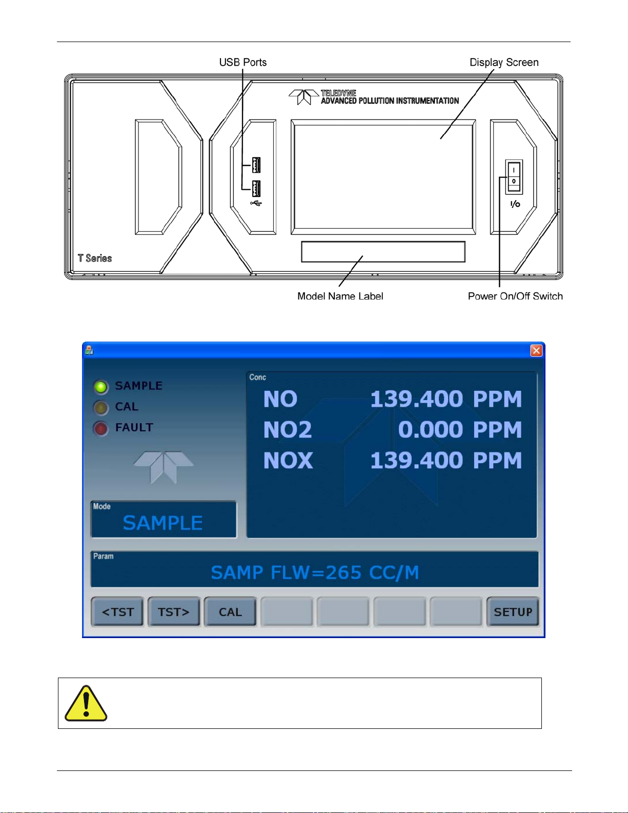
Teledyne API - Model T200H/T200M Operation Manual Getting Started
07270B DCN6512
Figure 3-1: Front Panel
27
Figure 3-2: Display Screen and Touch Control
CAUTION – Avoid Damaging Touch screen
Do not use hard-surfaced instruments such as pens to operate the touch screen.
Page 30

Getting Started Teledyne API - Model T200H/T200M Operation Manual
07270B DCN6512
The front panel liquid crystal display screen includes touch control. Upon analyzer startup, the screen shows a splash screen and other initialization indicators before the main
display appears, similar to Figure 3-2 above (may or may not display a Fault alarm). The
LEDs on the
display screen indicate the Sample, Calibration and Fault states; also on the
screen is the gas concentration field (Conc), which displays real-time readouts for the
primary gas and for the secondary gas if installed. The display screen also shows what
mode the analyzer is currently in, as well as messages and data (Param). Along the
bottom of the screen is a row of touch control buttons; only those that are currently
applicable will have a label. Table 3-1 provides detailed information for each component
of the screen.
Table 3-1: Display Screen and Touch Control Description
Field Description/Function
Status
Conc
Mode Displays the name of the analyzer’s current operating mode
Param
Control Buttons Displays dynamic, context sensitive labels on each button, which is blank when inactive until applicable.
LEDs indicating the states of Sample, Calibration and Fault, as follows:
Name Color State Definition
Off
On
SAMPLE Green
CAL Yellow
FAULT Red
Displays the actual concentration of the sample gas currently being measured by the analyzer in the
currently selected units of measure
Displays a variety of informational messages such as warning messages, operational data, test function
values and response messages during interactive tasks.
Blinking
Off
On
Blinking
Off
Blinking
Unit is not operating in sample mode, DAS is disabled.
Sample Mode active; Front Panel Display being updated; DAS data
being stored.
Unit is operating in sample mode, front panel display being updated,
DAS hold-off mode is ON, DAS disabled
Auto Cal disabled
Auto Cal enabled
Unit is in calibration mode
No warnings exist
Warnings exist
28
Figure 3-3 shows how the front panel display is mapped to the menu charts illustrated in
this manual. The Mode, Param (parameters), and Conc (gas concentration) fields in the
display screen are represented across the top row of each menu chart. The eight touch
control buttons along the bottom of the display screen are represented in the bottom row
of each menu chart.
Page 31

Teledyne API - Model T200H/T200M Operation Manual Getting Started
07270B DCN6512
29
Figure 3-3: Display/Touch Control Screen Mapped to Menu Charts
The rear panel is illustrated in Figure 3-4 and described in Table 3-2.
Page 32

Getting Started Teledyne API - Model T200H/T200M Operation Manual
07270B DCN6512
Figure 3-4: T200H/M Rear Panel Layout
Table 3-2: Rear Panel Description
Component Function
Cooling Fan
AC power
connector
Model label
SAMPLE
EXHAUST
SPAN 1
ZERO AIR
(option)
RX TX
COM 2
RS-232
DCE DTE
STATUS
ANALOG OUT
CONTROL IN
ALARM
ETHERNET
ANALOG IN
USB
Pulls ambient air into chassis through side vents and exhausts through rear.
Connector for three-prong cord to apply AC power to the analyzer.
CAUTION! The cord’s power specifications (specs) MUST comply with the power
specs on the analyzer’s rear panel Model number label
Identifies the analyzer model number and provides voltage and frequency specs
Connect a gas line from the source of sample gas here.
Calibration gases are also inlet here on units without zero/span valve options installed.
Connect an exhaust gas line of not more than 10 meters long here that leads outside
the shelter or immediate area surrounding the instrument.
On units with zero/span valve options installed, connect a gas line to the source of
calibrated span gas here.
Internal Zero Air: On units with zero/span valve options installed but no internal zero air
scrubber attach a gas line to the source of zero air here.
LEDs indicate receive (RX) and transmit (TX) activity on the when blinking.
Serial communications port for RS-232 or RS-485.
Serial communications port for RS-232 only.
Switch to select either data terminal equipment or data communication equipment
during RS-232 communication.
For outputs to devices such as Programmable Logic Controllers (PLCs).
For voltage or current loop outputs to a strip chart recorder and/or a data logger.
For remotely activating the zero and span calibration modes.
Option for concentration alarms and system warnings.
Connector for network or Internet remote communication, using Ethernet cable
Option for external voltage signals from other instrumentation and for logging these
signals.
Option for direct connection to laptop computer, using USB cable.
30
Page 33

Teledyne API - Model T200H/T200M Operation Manual Getting Started
07270B DCN6512
31
Figure 3-5: T200H/M Internal Layout
Page 34

Getting Started Teledyne API - Model T200H/T200M Operation Manual
07270B DCN6512
3.4. ELECTRICAL CONNECTIONS
Note To maintain compliance with EMC standards, it is required that the cable
length be no greater than 3 meters for all I/O connections, which include
Analog In, Analog Out, Status Out, Control In, Ethernet/LAN, USB, RS-232,
and RS-485.
Refer to Figure 3-4 for the location of the rear panel electrical and pneumatic
connections.
3.4.1. POWER CONNECTION
Attach the power cord to the analyzer and plug it into a power outlet capable of carrying
at least 10 A current at your AC voltage and that it is equipped with a functioning earth
ground.
CAUTION
CHECK THE VOLTAGE AND FREQUENCY SPECIFICATIONS ON THE REAR PANEL
LABEL SHOWING THE MODEL NAME AND NUMBER OF THE INSTRUMENT FOR
COMPATIBILITY WITH THE LOCAL POWER BEFORE PLUGGING THE T200H/M INTO
LINE POWER.
Do not plug in the power cord if the voltage or frequency is incorrect.
WARNING – RISK OF ELECTRIC SHOCK
HIGH VOLTAGES ARE PRESENT INSIDE THE INSTRUMENT’S CHASSIS.
POWER CONNECTION MUST HAVE FUNCTIONING GROUND CONNECTION.
DO NOT DEFEAT THE GROUND WIRE ON POWER PLUG.
TURN OFF ANALYZER POWER BEFORE DISCONNECTING OR
CONNECTING ELECTRICAL SUBASSEMBLIES.
DO NOT OPERATE WITH COVER OFF.
The T200H/M analyzer can be configured for both 100-130 V and 210-240 V at either
50 or 60 Hz. To avoid damage to your analyzer, make sure that the AC power voltage
matches the voltage indicated on the rear panel serial number label and that the
frequency is between 47 and 63 Hz.
32
Page 35

Teledyne API - Model T200H/T200M Operation Manual Getting Started
07270B DCN6512
3.4.2. ANALOG INPUTS (OPTION 64) CONNECTIONS
The Analog In connector is used for connecting external voltage signals from other
instrumentation (such as meteorological instruments) and for logging these signals in the
analyzer’s internal DAS. The input voltage range for each analog input is 0-10 VDC,
and the input impedance is nominally 20kΩ in parallel with 0.1µF.
Figure 3-6: Analog In Connector
Pin assignments for the Analog In connector are presented in Table 3-3.
Table 3-3: Analog Input Pin Assignments
PIN DESCRIPTION
1 Analog input # 1 AIN 1
2 Analog input # 2 AIN 2
3 Analog input # 3 AIN 3
4 Analog input # 4 AIN 4
5 Analog input # 5 AIN 5
6 Analog input # 6 AIN 6
7 Analog input # 7 AIN 7
8 Analog input # 8 AIN 8
GND Analog input Ground N/A
1
See Section 4.7 for details on setting up the DAS.
3.4.3. ANALOG OUTPUT CONNECTIONS
The T200H/M is equipped with four analog output channels accessible through a
connector on the back panel of the instrument. Each of these outputs may be set to
reflect the value of any of the instrument’s DAS data types. (see Table A-6 of T200H/M
Appendix A – P/N 05147).
The following table lists the default settings for each of these channels. To change these
settings, see Sections 6.13.4
DAS
PARAMETER
1
33
Page 36

Getting Started Teledyne API - Model T200H/T200M Operation Manual
A
A
07270B DCN6512
Table 3-1: Analog Output Data Type Default Settings
PARAMETER
DATA TYPE
A1 A2 A3 A4
1
NXCNC1 NOCNC1 N2CNC1 NXCNC2
CHANNEL DEFAULT SETTING
3
RANGE 0 - 5 VDC2
REC OFS 0 mVDC
AUTO CAL. ON
CALIBRATED NO
OUTPUT ON
SCALE 100 ppm
UPDATE 5 sec
1
See Table A-6 of T200H/M Appendix A for definitions of these DAS data types
2
Optional current loop outputs are available for analog output channels A1-A3.
3
On analyzers with O2 sensor options installed, DAS parameter O2CONC is assigned to output A4.
To access these signals attach a strip chart recorder and/or data-logger to the appropriate
contacts of the analog output connecter on the rear panel of the analyzer.
A1
+ - + - + - + -
NALOG OUT
2 A3 A4
Figure 3-7: Analog Output Connector
Table 3-4: Analog Output Pin-Outs
PIN ANALOG OUTPUT VOLTAGE SIGNAL CURRENT SIGNAL
1 V Out I Out +
2
3 V Out I Out +
4
5 V Out I Out +
6
7 V Out Not Available
8
A1
Ground I Out -
A2
Ground I Out -
A3
Ground I Out -
A4
Ground Not Available
3.4.4. CONNECTING THE STATUS OUTPUTS
The analyzer’s status outputs to interface with a device that accepts logic-level digital
inputs, such as programmable logic controller (PLC) chips, are accessed through a 12
pin connector labeled STATUS on the analyzer’s rear panel.
34
Page 37

Teledyne API - Model T200H/T200M Operation Manual Getting Started
07270B DCN6512
1 2 3 4 5 6 7 8 D +
SYSTEM OK
CONC VALID
HIGH RANGE
ZERO CAL
STATUS
MODE
SPAN CAL
DIAGNOSTIC
LOW SPAN
FOR PINS 1-8
EMITTER BUS
Figure 3-8: Status Output Connector
Note Most PLCs have internal provisions for limiting the amount of current the
input will draw. When connecting to a unit that does not have this feature,
external resistors must be used to limit the current through the individual
transistor outputs to ≤50mA (120 Ω for 5V supply).
Table 3-5: Status Output Signals
PIN # STATUS CONDITION (ON = CONDUCTING)
1
2
3
4
5
6
7
8
D
+
SYSTEM OK
CONC VALID
HIGH RANGE
ZERO CAL
SPAN CAL
DIAG MODE
LOW SPAN CAL
Not Used
EMITTER BUS
Not Used
DC POWER
Digital Ground
ON if no faults are present.
ON if concentration measurement (NO, NO2 or NOx) is valid.
OFF any time the hold-off feature is active.
ON if unit is in high range of the Auto Range Mode.
ON whenever the instrument is in ZERO point calibration mode.
ON whenever the instrument is in SPAN point calibration mode.
ON whenever the instrument is in diagnostic mode.
ON when in low span calibration (optional equipment necessary)
The emitters of the transistors on pins 1-8 are tied together.
+ 5 VDC, 300 mA (combined rating with Control Output, if used).
The ground level from the analyzer’s internal DC power supplies
35
Page 38

Getting Started Teledyne API - Model T200H/T200M Operation Manual
07270B DCN6512
3.4.5. CURRENT LOOP ANALOG OUTPUTS (OPT 41) SETUP
This option adds isolated, voltage-to-current conversion circuitry to the analyzer’s
analog outputs. This option may be ordered separately for the first three of the analog
outputs and can be installed at the factory or added later. Call Teledyne API sales for
pricing and availability.
The current loop option can be configured for any output range between 0 and 20 mA
(for example 0-20, 2-20 or 4-20 mA). Information on calibrating or adjusting these
outputs can be found in Section 4.13.6.3.
CAUTION – Avoid Warranty Invalidation
Printed circuit assemblies (PCAs) are sensitive to electro-static discharges too small
to be felt by the human nervous system. Damage resulting from failure to use ESD
protection when working with electronic assemblies will void the instrument warranty.
See A Primer on Electro-Static Discharge in this manual for more information on preventing
ESD damage.
36
Figure 3-9: Current Loop Option Installed on the Motherboard
Page 39

Teledyne API - Model T200H/T200M Operation Manual Getting Started
07270B DCN6512
3.4.5.1. Converting Current Loop Analog Outputs to Standard Voltage Outputs.
CAUTION – Avoid Warranty Invalidation
Printed circuit assemblies (PCAs) are sensitive to electro-static discharges too small
to be felt by the human nervous system. Damage resulting from failure to use ESD
protection when working with electronic assemblies will void the instrument warranty.
See A Primer on Electro-Static Discharge in this manual for more information on preventing
ESD damage.
To convert an output configured for current loop operation to the standard 0 to 5 VDC
output operation:
1. Turn off power to the analyzer.
2. If a recording device was connected to the output being modified, disconnect it.
3. Remove the top cover:
a. Remove the set screw located in the top, center of the rear panel
b. Remove the screws fastening the top cover to the unit (four per side).
c. Lift the cover straight up.
4. Disconnect the current loop option PCA from the appropriate connector on the
motherboard.
5. Place a shunt between the leftmost two pins of the connector (see Figure 3-9).
6.
Reattach the top case to the analyzer.
The analyzer is now ready to have a voltage-sensing, recording device attached to that
output.
37
Page 40

Getting Started Teledyne API - Model T200H/T200M Operation Manual
07270B DCN6512
3.4.6. CONNECTING THE CONTROL INPUTS
Control Inputs are used to remotely activate the zero and span calibration modes. Locate
the 10-pin connector labeled CONTROL IN on the analyzer’s rear panel.
There are two methods for energizing the control inputs. The internal +5V available
from the pin labeled “+” is the most convenient method. However, if full isolation is
required, an external 5 VDC power supply should be used.
A B C D E F U +
SPAN CAL
ZERO CAL
RANGE HI
LOW SPAN
CONTROL IN
CONTROL IN
A B C D E F U +
LOW SPAN
RANGE HI
5 VDC Power
SPAN CAL
ZERO CAL
-
Local Power Connections
Figure 3-10: Control Input Connector
Table 3-6: Control Input Signals
INPUT # STATUS DEFINITION ON CONDITION
A REMOTE ZERO CAL
B REMOTE SPAN CAL
C REMOTE LO SPAN CAL
D REMOTE RANGE HI
E SPARE
F SPARE
Digital Ground
U External Power input Input pin for +5 VDC required to activate pins A - F.
+ 5 VDC output
The analyzer is placed in Zero Calibration mode. The mode field of
the display will read ZERO CAL R.
The analyzer is placed in Span Calibration mode. The mode field of
the display will read SPAN CAL R.
The analyzer is placed in low span calibration mode as part of
performing a low span (midpoint) calibration. The mode field of the
display will read LO CAL R.
The analyzer is placed into high range when configured for dual
ranges..
The ground level from the analyzer’s internal DC power supplies
(same as chassis ground).
Internally generated 5V DC power. To activate inputs A - F, place a
jumper between this pin and the “U” pin. The maximum amperage
through this port is 300 mA (combined with the analog output supply,
if used).
External Power Connections
Supply
+
38
Page 41

Teledyne API - Model T200H/T200M Operation Manual Getting Started
A
07270B DCN6512
3.4.7. CONNECTING THE ALARM RELAY OPTION (OPT 61)
The T200H/M can be equipped with a set of 2 concentration alarms. Each alarm can be
independently enabled or disabled as well as programmed with its own, individual alarm
limit point (see Section 4.14 for details on programming the alarms).
The status of each alar
m is available via a set of alarm relay outputs located on the lower
right hand corner of the analyzer’s rear panel (see Figure 3-4). While there are four
relay
outputs on the back of the analyzer, only Two of the outputs correspond to the
instrument’s two concentration alarms.
Table 5-5: Alarm Relay Output Assignments
RELAY NAME
ASSIGNED ALARM
1
ST_SYSTEM OK2 is a second system OK status alarm available on some analyzers.
ST_SYSTEM_OK2
AL1 AL2 AL3 AL4
CONCENTRATION
1
ALARM 1
LARM OUT
AL1 AL2 AL3 AL4
NO C NC NO C NC NO C NC NO C NC
CONCENTRATION
ALARM 2
SPARE
ST_SYSTEM_OK2
(Optional Alert)
Figure 3-11: Alarm Relay Output Pin Assignments
CONCENTRATION
ALARM 1
CONCENTRATION
ALARM 2
SPARE
Each of the two concentration relay outputs has 3-pin connections that allow the relay to
be connected for either normally open or normally closed operation. Table 3-7 describes
how to connect the alar
39
m relays.
Page 42

Getting Started Teledyne API - Model T200H/T200M Operation Manual
07270B DCN6512
Table 3-7: Concentration Alarm Relay Output Operation
RELAY FUNCTION
Concentration Alarm 1
Active
AL2
Concentration Alarm 1
Inactive
Concentration Alarm 2
Active
AL3
Concentration Alarm 2
Inactive
1
NO = Normally Open operation.
C = Common
NC = Normally Closed operation.
RELAY PIN
N
O
STATE
C
1
N
C
Gas concentration level is above the trigger limit set for
CONC_ALARM_1
DAS Trigger CONCW1 ACTIVATED
CONC ALARM1 WARN appears on Analyzer Display
Gas concentration level is below the trigger limit set for
CONC_ALARM_1
Gas concentration level is above the trigger limit set for
CONC_ALARM_2
DAS Trigger CONCW2 ACTIVATED
CONC ALARM2 WARN appears on Analyzer Display
Gas concentration level is below the trigger limit set for
CONC_ALARM_2
COMMENTS
3.4.8. CONNECTING THE COMMUNICATIONS PORTS
For RS-232 or RS-485 (option) communications through the analyzer’s two serial
interface ports, refer to Section 4.11 for information and connection instructions.
3.4.8.1. Connecting to a LAN or the Internet
For network or Internet communication with the analyzer, connect an Ethernet cable
from the analyzer’s rear panel Ethernet interface connector to an Ethernet port. See
Section 4.11.7 for configuration instructions.
Note
The T200H/M firmware supports dynamic IP addressing or DHCP. If your
network also supports DHCP, the analyzer will automatically configure its
LAN connection appropriately. If your network does not support DHCP,
see Section 4.11.7.2 for instructions on manually configuring the LAN
connection.
3.4.8.2. Connecting to a Personal Computer (PC)
If the USB port is configured for direct communication between the analyzer and a
desktop or a laptop PC, connect a USB cable between the analyzer and the PC or laptop
USB ports, and follow the set-up instructions in Section 4.11.8. (RS-485 communication
is not available with the USB co
m port option).
40
Page 43

Teledyne API - Model T200H/T200M Operation Manual Getting Started
07270B DCN6512
3.4.8.3. Connecting to a Multidrop Network
The multidrop option is used with RS-232 and utilizes both com port DB-9 connectors
(RS-232 and COM2) on the rear panel to enable communications of up to eight
analyzers with the host computer over a chain of RS-232 cables. It is subject to the
distance limitations of the RS 232 standard.
The option consists of a small printed circuit assembly, which is seated on the analyzer’s
CPU card (see Figure 3-12). One Option 62 is required for each analyzer along with one
6’ straig
If your unit has a Teledyne API RS-232 multidrop card (Option 62), see Section 4.11.9
for instructions on setting
ht-through, DB9 male DB9 Female cable (P/N WR0000101).
it up.
Figure 3-12: T200H/M Multidrop Card
41
Page 44

Getting Started Teledyne API - Model T200H/T200M Operation Manual
07270B DCN6512
3.5. PNEUMATIC CONNECTIONS
Note To prevent dust from getting into the analyzer, it was shipped with small
plugs inserted into each of the pneumatic fittings on the rear panel.
Remove and store the dust plugs for future use, such as storage, moving,
shipping.
CAUTION!
Do not operate this instrument until you’ve removed dust plugs from SAMPLE and EXHAUST
ports on the rear panel!
Table 3-8: Inlet / Outlet Connector Descriptions
REAR PANEL LABEL FUNCTION
SAMPLE
EXHAUST
SPAN
ZERO AIR
Connects the sample gas to the analyzer. When operating the analyzer
without zero span option, this is also the inlet for any calibration gases.
Connects the exhaust of the analyzer with the external vacuum pump.
On Units with a zero/span valve, this port connects the external calibration gas
to the analyzer.
On Units with a zero/span valve, this port connects the zero air gas or the zero
air cartridge to the analyzer.
3.5.1. ABOUT ZERO AIR AND CALIBRATION (SPAN) GASES
3.5.1.1. Zero Air
Zero air or zero calibration gas is defined as a gas that is similar in chemical
composition to the measured medium but without the gas to be measured by the
analyzer, in this case NO and NO
air scrubber option, it is capable of creating zero air from ambient air.
If your application is not a measurement in ambient air, the zero calibration gas should
be matched to the matrix of the measured medium. Pure nitrogen could be used as a
zero gas for applications where NO
apply if measuring NO
more information.
3.5.1.2. Calibration (Span) Gas
Calibration (or Span) gas is a gas specifically mixed to match the chemical composition
of the type of gas being measured at near full scale of the desired measurement range.
In this case, NO
recommended that you use a span gas with an NO
measurement range for your application.
EXAMPLE: If the application is to measure between 0 ppm and 500 ppm, an
appropriate span gas concentration would be 400 ppm NO
in a matrix that does not contain oxygen, see Section 8.3.11 for
X
NO and NO2 measurements made with the T200H/M, it is
X,
. If your analyzer is equipped with an external zero
2
is measured in nitrogen. Special considerations
X
concentration equal to 80% of the
.
x
42
Page 45

Teledyne API - Model T200H/T200M Operation Manual Getting Started
07270B DCN6512
Even though NO gas in nitrogen could be used as a span gas, the matrix of the balance
gas is different and may cause interference problems or yield incorrect calibrations. The
same applies to gases that contain high concentrations of other compounds (for example,
or H2O). The span gas should match all concentrations of all gases of the measured
CO
2
medium as closely as possible.
Cylinders of calibrated NO gas traceable to NIST-standard reference materials
specifications (also referred to as EPA protocol calibration gases) are commercially
available.
Table 3-9: NIST-SRM's Available for Traceability of NO
NIST-SRM4 TYPE
2627a
2628a
2629a
1683b
1684b
1685b
1686b
1687b
2630
2631a
2635
2636a
2631a
1684b
Nitric Oxide (NO) in N
Nitric Oxide (NO) in N
2
2
Nitric Oxide (NO) in N2
Nitric Oxide (NO) in N
Nitric Oxide (NO) in N
Nitric Oxide (NO) in N
Nitric Oxide (NO) in N
2
2
2
2
Nitric Oxide (NO) in N2
Nitric Oxide (NO) in N
Nitric Oxide (NO) in N
Nitric Oxide (NO) in N
2
2
2
Nitric Oxide (NO) in N2
Oxides of Nitrogen (NOx) in N2
Oxides of Nitrogen (NO
) in N2
x
Calibration Gases
x
NOMINAL
CONCENTRATION
5 ppm
10 ppm
20 ppm
50 ppm
100 ppm
250 ppm
5000 ppm
1000 ppm
1500 ppm
3000 ppm
800 ppm
2000 ppm
3000 ppm
100 ppm
Note If a dynamic dilution system such as the Teledyne API Model T700 is used
to dilute high concentration gas standards to low, ambient
concentrations, make sure that the NO concentration of the reference gas
matches the dilution range of the calibrator. Choose an NO gas
concentration that is in the middle of the dilution system’s range.
43
Page 46

Getting Started Teledyne API - Model T200H/T200M Operation Manual
07270B DCN6512
3.5.2. PNEUMATIC CONNECTIONS TO T200H/M BASIC CONFIGURATION
Figure 3-13 and Figure 3-14 show the most common configurations for gas supply and
exhaust lines to the Model T200H/M analyzer. Please refer to Figure 3-4 for the
locations of p
neumatic connections on the rear panel and Table 3-2 for the descriptions.
Note
NOx Gas
(High Concentration)
MODEL 701
Zero Gas
Generator
Sample and calibration gases should only come into contact with PTFE
(Teflon) or glass or materials. They should not come in contact with FEP
or stainless steel materials.
VENT here if input
is pressurized
MODEL T700
Gas Dilution
Calibrator
VENT (if no vent
on calibrator)
Source of
SAMPLE GAS
Removed during
calibration
SAMPLE
EXHAUST
Instrument
Chassis
PUMP
Figure 3-13: Pneumatic Connections–Basic Configuration–Using Gas Dilution Calibrator
44
Page 47

Teledyne API - Model T200H/T200M Operation Manual Getting Started
07270B DCN6512
NOX Gas
(High Concentration)
Manual
Control Valve
Figure 3-14: Pneumatic Connections–Basic Configuration–Using Bottled Span Gas
3-way Valve
VENT
MODEL 701
Zero Gas
Generator
PUMP
Source of
SAMPLE GAS
Removed during
calibration
VENT here if input
is pressurized
SAMPLE
EXHAUST
Instrument
Chassis
45
Page 48

Getting Started Teledyne API - Model T200H/T200M Operation Manual
07270B DCN6512
1. Attach a 1/4" exhaust line between the external pump and the EXHAUST port of the
analyzer.
2. Attach an additional 1/4" exhaust port of the pump.
CAUTION
The exhaust from the analyzer must be vented outside the shelter or immediate
area surrounding the instrument and conform to all safety requirements using
a maximum of 10 meters of 1/4” PTFE tubing.
3. Attach a sample inlet line to the SAMPLE inlet port. Ideally, the pressure of the
sample gas should be equal to ambient atmospheric pressure.
Note Maximum pressure of any gas at the SAMPLE inlet should not exceed 1.5
in-Hg above ambient pressure and ideally should equal ambient
atmospheric pressure.
In applications where the sample gas is received from a pressurized
manifold, a vent must be provided to equalize the sample gas with
ambient atmospheric pressure before it enters the analyzer.
The vented gas must be routed outside the immediate area or shelter
surrounding the instrument.
4. Once the appropriate pneumatic connections have been made, check all pneumatic
fittings for leaks using procedures defined in Section 7.5.1.
Figure 3-15 and Figure 3-16 show the internal pneumatic flow of the standard
configuration of the T200H and T200M respectively.
46
Page 49

Teledyne API - Model T200H/T200M Operation Manual Getting Started
07270B DCN6512
Figure 3-15: T200H Internal Pneumatic Block Diagram - Standard Configuration
47
Page 50

Getting Started Teledyne API - Model T200H/T200M Operation Manual
07270B DCN6512
Exhaust
X
NO
SAMPLE
INLET
EXHAUST
OUTLET
Scrubber
GAS
GAS
NO/NO
X
VALVE
NO
2
Converter
COM
NC
NO
Orifice Dia.
0.007"
EXHAUST MANIFOLD
REACTION
Orifice Dia.
0.004"
Filter
COMNO
NC
AUTOZERO
VALVE
CELL
PMT
FLOW PRESSURE
SENSOR PCA
VACUUM
PRESSURE
SENSOR
GENERATOR
Orifice Dia.
0.007"
SAMPLE
PRESSURE
SENSOR
O
3
O
3
Destruct
O3 FLOW
SENSOR
Note
PUMP
PERMAPURE
DRYER
INSTRUMENT CHASSIS
Figure 3-16: T200M Internal Pneumatic Block Diagram - Standard Configuration
Pneumatic Diagrams do not reflect the physical layout of the instrument.
The most significant differences between the T200H and T200M versions in regards to
pneumatic flow are:
A bypass line leading directly from the particulate filter to the exhaust manifold is
present on the T200H, but not in the T200M.
The diameter of the critical flow orifice controlling the gas flow into the sample
chamber is smaller and therefore the flow rate of sample gas through the instrument
is lower.
48
Page 51

Teledyne API - Model T200H/T200M Operation Manual Getting Started
07270B DCN6512
3.5.3. CONNECTIONS WITH INTERNAL VALVE OPTIONS INSTALLED
If your analyzer is equipped with either the zero/span valve option (50A) or the 2-span
point valve option (50D), the pneumatic connections should be made as shown in Figure
3-17 and
Figure 3-18:
MODEL T700
Gas Dilution
Calibrator
Source of
VENT here if input
is pressurized
SAMPLE Gas
at HIGH Span
Concentration
Calibrated NO
MODEL 701
Zero Gas
Generator
PUMP
Sample
Exhaust
Span Point
Zero Air
Instrument
Chassis
Figure 3-17: Pneumatic Connections–With Zero/Span Valve Option (50A)
On/Off
at HIGH Span
Concentration
Calibrated NO
Calibrated NO
Valves
VENT
at LOW Span
Concentration
VENT
Source of
SAMPLE Gas
PUMP
VENT here if input
is pressurized
Sample
Exhaust
High Span Point
Low Span Point
Zero Air
Instrument
Chassis
Figure 3-18: Pneumatic Connections–With 2-Span Point Option (50D) –Using Bottled Span Gas
Once the appropriate pneumatic connections have been made, check all pneumatic
fittings for leaks using the procedures defined in Section 7.5.
49
Page 52

Getting Started Teledyne API - Model T200H/T200M Operation Manual
07270B DCN6512
3.5.3.1. Ambient Zero/Ambient Span Valves (OPT 50A)
The Model T200H/M NOx analyzer can be equipped with a zero/span valve option for controlling the flow of
calibration gases generated from external sources. This option contains two solenoid valves located inside the
analyzer that allow the user to switch either zero, span or sample gas to the instrument’s sensor.
The user can control these valves from the front panel keyboard either manually or by activating the instrument’s
CAL or AutoCal features (Section 5.8). The valves may also be opened and closed remotely through the serial
ports (Se
ction 4.11) or through the external, digital control inputs (Section 4.15).
This optio
the zero air source (ambient air). The scrubber is filled with 50% Purafil Chemisorbant
NO
n also includes a two-stage, external zero air scrubber assembly that removes all NO and NO
) and 50% activated charcoal (for removal of NO2). This assembly also includes a small particle filter to
2
®
(for conversion of NO to
from
2
prevent scrubber particles to enter the analyzer as well as two more rear panel fittings so each gas can enter the
analyzer separately.
Figure 3-19 and Figure 3-20 show the internal, pneumatic layouts with the zero/span valve option installed for a
Model T2
00H and T200M respectively.
O3 FLOW
SENSOR
50
Exhaust
NO
X
Scrubber
EXHAUST MANIFOLD
Filter
Figure 3-19: T200H – Internal Pneumatics with Ambient Zero-Span Valve Option 50A
Page 53

Teledyne API - Model T200H/T200M Operation Manual Getting Started
07270B DCN6512
Figure 3-20: T200M – Internal Pneumatics with Ambient Zero-Span Valve Option 50A
Table 3-10: Zero/Span Valve States
MODE VALVE CONDITION
SAMPLE
ZERO
CALIBRATION
SPAN
CALIBRATION
Sample/Cal Open to sample gas inlet
Zero/Span Open to zero air inlet
Sample/Cal Open to zero/span inlet (activated)
Zero/Span Open to zero air inlet
Sample/Cal Open to zero/span inlet (activated)
Zero/Span Open to span gas inlet / IZS gas (activated)
The state of the zero/span valves can also be controlled:
Manually from the analyzer’s front panel by using the SIGNAL I/O controls located
under the DIAG Menu (Section 4.13.2),
By activating the instrument’s AutoCal feature (Section 5.8),
Remotely by using the external digital control inputs (Section 4.15.1.2) or Ethernet
option.
Remotely through the RS-232/485 serial I/O ports (Section 4.11).
51
All supply lines should be vented outside of the analyzer’s enclosure. In order to
prevent back-diffusion and pressure drop effects, these vent lines should be between 2
and 10 meters in length.
Page 54

Getting Started Teledyne API - Model T200H/T200M Operation Manual
07270B DCN6512
3.5.3.2. Zero Scrubber/Dual Pressurized Span Valve (OPT 50D)
The zero air scrubber of Option 50D is a cartridge, which is used to produce and supply
zero air to the analyzer’s ZERO inlet port. The cartridge mounts to the outside rear panel
and contains two chemicals: 50% volume of Purafil Chemisorbant to convert NO to
, followed by 50% volume of charcoal to absorb NO2.
NO
2
The dual pressurized span valves of Option 50D are a special set of valves that allows
two separate NO
Typically these two gas mixtures will come from two, separate, pressurized bottles of
certified calibration gas: one mixed to produce a NO, NO
to the expected span calibration value for the application and the other mixed to produce
a concentration at or near the midpoint of the intended measurement range. Individual
gas inlets, labeled HIGH SPAN and LOW SPAN are provided at the back on the
analyzer.
The valves allow the user to switch between the two sources via the front panel
touchscreen control buttons or from a remote location by way of either the analyzer’s
digital control inputs or by sending commands over its serial I/O port(s).
Note The analyzer’s software only allows the SLOPE and OFFSET to be
calculated when sample is being routed through the HIGH SPAN inlet.
The LOW SPAN gas is for midpoint reference checks only.
mixtures to enter the analyzer from two independent sources.
x
or NOx concentration equal
2
52
Page 55

Teledyne API - Model T200H/T200M Operation Manual Getting Started
07270B DCN6512
The state of the optional valves can be controlled:
Manually from the analyzer’s front panel by using the SIGNAL I/O submenu located
under the DIAG menu (Section 4.13.2),
By activating the instrument’s CAL or AutoCal features (Section 5.8),
Remotely by using the external digital control inputs (Section 4.15.1.2) or Ethernet.
Remotely through the RS-232/485 serial I/O ports (Section 4.11).
Table 3-11:
MODE VALVE CONDITION
SAMPLE
ZERO
CAL
HIGH
SPAN
CAL
Low Span
Check
Zero Gas Valve
High Span Valve
Low Span Valve
Zero Gas Valve
High Span Valve
Low Span Valve
Zero Gas Valve
High Span Valve
Low Span Valve
Zero Gas Valve
High Span Valve
Low Span Valve
Two-Point Span Valve Operating States
Sample/Cal
Sample/Cal
Open to SAMPLE inlet
Closed to ZERO AIR inlet
Closed to HIGH SPAN inlet
Closed to LOW SPAN inlet
Closed to SAMPLE inlet
Open to ZERO AIR inlet
Closed to HIGH SPAN inlet
Closed to LOW SPAN inlet
Sample/Cal
Closed to SAMPLE inlet
Closed to ZERO AIR inlet
Open to HIGH SPAN inlet
Closed to LOW SPAN inlet
Sample/Cal
Closed to SAMPLE inlet
Closed to ZERO AIR inlet
Closed to HIGH SPAN inlet
Open to LOW SPAN inlet
53
Page 56

Getting Started Teledyne API - Model T200H/T200M Operation Manual
07270B DCN6512
This page intentionally left blank.
54
Page 57

Teledyne API - Model T200H/T200M Operation Manual Getting Started
07270B DCN6512
55
Figure 3-21: T200H - Internal Pneumatics for Zero Scrubber/Dual Pressurized Span, Option 50D
Page 58

Getting Started Teledyne API - Model T200H/T200M Operation Manual
07270B DCN6512
56
Figure 3-22: T200M - Internal Pneumatics for Zero Scrubber/Dual Pressurized Span, Option 50D
Page 59

Teledyne API - Model T200H/T200M Operation Manual Getting Started
07270B DCN6512
3.5.3.3. Internal Flow for O2 Sensor Option 65A
Please see Section 3.7.2 for calibration connections and method.
NO/NO
SAMPLE
GAS
INLET
EXHAUST
GAS
OUTLET
OPTION, O2
SENSOR, P/N 04453
Sensor
O
2
Orifice Dia.
0.004"
Converter
Orifice Dia.
0.007"
NO
X
VALVE
2
NC
COMNO
NC
COM
NO
FLOW PRESSURE
SENSOR PCA
VACUUM
PRESSURE
SENSOR
AUTOZERO
VALVE
Orifice Dia.
0.007"
SAMPLE
PRESSURE
SENSOR
O
3
GENERATOR
O3 FLOW
SENSOR
PUMP
Exhaust
X
NO
EXHAUST MANIFOLD
Scrubber
Filter
Orifice Dia.
0.004"
PERMAPURE
DRYER
REACTION
CELL
PMT
Figure 3-23: T200H – Internal Pneumatics with O2 Sensor Option 65A
O
3
Destruct
INSTRUMENT CHASSIS
57
Page 60

Getting Started Teledyne API - Model T200H/T200M Operation Manual
07270B DCN6512
Figure 3-24: T200M – Internal Pneumatics with O
Sensor Option 65A
2
58
Page 61

p p
07270B DCN6512
3.6. INITIAL OPERATION
If the presence of ozone is detected at any time, call Teledyne API Technical Support as soon
If you are unfamiliar with the theory of operation of the T200H/M analyzer, we
recommend that you read Section 8 before proceeding. For information on navigating
the analy
3.6.1. STARTUP
After the electrical and pneumatic connections are made, an initial functional check is in
order. Turn on the instrument. The pump and exhaust fan should start immediately. The
display will briefly show a logo splash screen at the start of initialization.
The analyzer should automatically switch to Sample Mode after completing the boot-up
sequence and start monitoring NO
During the warm-up period, the front panel display may show messages in the
Parameters field, such as WARNING messages.
zer’s software menus, see the menu trees described in Appendix A.
CAUTION!
as possible:
800-324-5190 or email: sda_techsupport@teledyne.com
, NO, NO2 gases. Allow a one-hour warm-up period.
X
3.6.2. WARNING MESSAGES
During warm-up, internal temperatures and other parameters may be outside of specified
limits. The software will suppress most warning conditions for 30 minutes after power
up.
SAMPLE HVPS WARNING NOX = 0.0
TEST CAL MSG CLR SETUP
SAMPLE RANGE=200.0 PPM NO = 0.0
< TST TST > CAL MSG CLR SETUP
SAMPLE HVPS WARNING NOX = 0.0
TEST CAL MSG CLR SETUP
NOTE:
If the warning message persists after several attempts to
clear it, the message may indicate a real problem and not
an artifact of the warm-u
Section 4.2.2 provides a table of warning messages with their definitions and the steps to
view and clear them. If warning messages persist after 30 minutes, investigate their
cause using the troubleshooting guidelines in Section 7.
eriod
TEST deactivates warning
messages
MSG activates warning
messages.
<TST TST> keys replaced with
TEST key
Press CLR to clear the current
message.
If more than one warning is active, the
next message will take its place
Once the last warning has been
cleared, the analyzer returns to
SAMPLE mode
59
Page 62

Getting Started Teledyne API - Model T200H/T200M Operation Manual
A
1
1
p
g
07270B DCN6512
3.6.3. FUNCTIONAL CHECK
After the analyzer’s components have warmed up for at least 30 minutes, verify that the
software properly supports any hardware options that were installed.
Check to make sure that the analyzer is functioning within allowable operating
parameters. Appendices A and C include a list of test functions viewable from the
analyzer’s front panel as well as their expected values. These functions are also useful
tools for diagnosing performance problems with your analyzer (Section 7). The
enclosed Final Test and
before the instrument left the factory. To view the current values of these test functions
press the <TST TST> buttons:
Validation Data Sheet (part number 04490) lists these values
SAMPLE A1:NXCNC1=100 PPM NOX = XXX
< TST TST > CAL SETUP
1
1
1
2
Toggle <TST TST> to scroll
throu
h list of functions
default se tting s f or us er
selectable reporting range
settings.
2
Only appears if O2 sensor
tion is installed.
o
1:NXCNC1=100 PPM
A2:N0CNC1=100 PPM
A3:N2CNC1=25 PPM
A4:NXCNC2=100%
NOX STB
SAMP FLOW
OZO NE FLO W
PM T
NORM PMT
AZERO
HVPS
RCELL TEMP
BOX TEMP
PMT TEM P
MF TEMP
O2 CELL TEMP
MOLY TEMP
RCEL
SAMP
NOX SLOPE
NOX OFFSET
NO SLOPE
NO OFFSET
O2 SLO PE
O2 OFFSET
TIME
2
2
60
Page 63

Teledyne API - Model T200H/T200M Operation Manual Getting Started
07270B DCN6512
3.7. CALIBRATION
An initial calibration and functional check should be conducted upon first-time startup.
Note
Once you have completed the followng set-up procedures, please fill out
the quality questionnaire that was shipped with your unit and return it to
Teledyne API.
This information is vital to our efforts in continuously improving our
service and our products. Thank you.
3.7.1. BASIC NOX CALIBRATION PROCEDURE
The initial calibration should be carried out using the same reporting range set up as
used during the analyzer’s factory calibration. This will allow you to compare your
calibration results to the factory calibration as listed on the Final Test and Validation
Data Sheet.
The following procedure assumes that the instrument does not have any of the available
valve options installed. Section 5 contains instructions for calibrating instruments with
these options.
If both avail
instrument’s analog outputs e.g. NXCNC1 and NXCNC2, separate calibrations should
be carried out for each parameter.
Use the LOW button when calibrating for NXCNC1
able DAS parameters for a specific gas type are being reported via the
Use the HIGH button when calibrating for NXCNC2.
See Sections 4.13.3 and 4.13.4 for more information on analog output reporting ranges.
61
Page 64

Getting Started Teledyne API - Model T200H/T200M Operation Manual
07270B DCN6512
STEP 1 - Set Units:
To select the concentration units of measure press:
SAMPLE A1:NXCNC1=100PPM NOX=XXX.X
< TST TST > CAL SETUP
SETUP X.X PRIMARY SETUP MENU
CFG DAS RNGE PASS CLK MORE EXIT
SETUP X.X RANGE CONTROL MENU
UNIT DIL EXIT
SETUP X.X CONC UNITS: PPM
Press this button to
PPM MGM ENTR EXIT
select the
concentration units
of measure:
PPM or MGM
62
Page 65

Teledyne API - Model T200H/T200M Operation Manual Getting Started
07270B DCN6512
STEP 2 - Dilution Ratio:
If the dilution ratio option is enabled on your T200H/M and your application involves
diluting the sample gas before it enters the analyzer, set the dilution ratio as follows:
SAMPLE A1:NXCNC1=100PPM NOX=XXX.X
< TST TST > CAL SETUP
SETUP X.X RANGE CONTROL MENU
SETUP X.X PRIMARY SETUP MENU
CFG DAS RNGE PASS CLK MORE EXIT
Toggle these
buttons to select the
dilution ratio factor
UNIT DIL EXIT
SETUP X.X DIL FACTOR:1.0 Gain
0 0 0 0 .0 ENTR EXIT
EXIT ignores the new
setting and returns to the
previous display.
ENTR accepts the new
setting and returns to the
previous display..
63
Page 66

Getting Started Teledyne API - Model T200H/T200M Operation Manual
07270B DCN6512
STEP 3 – Set NOx and NO span gas concentrations :
Set the expected NO and NOx span gas concentration. These should be 80% of range of
concentration values likely to be encountered in this application. The default factory
setting is 100 ppm. If one of the configurable analog outputs is to be set to transmit
concentration values, use 80% of the reporting range set for that output (see Section
4.13.4)
you supply NO span gas to the analyzer as well as NO
If
and NO
span gas concentrations need to be identical.
x
SAMPLE A1:NXCNC1=100PPM NOX=XXX.X
< TST TST > CAL SETUP
SAMPLE GAS TO CAL:NOX
NOX O2 ENTR EXIT
SAMPLE RANGE TO CAL:LOW
LOW HIGH ENTR EXIT
M-P CAL A1:NXCNC1 =100PPM NOX=X.XXX
<TST TST> ZERO SPAN CONC EXIT
M-P CAL CONCENTRATION MENU
NOX NO CONV EXIT
M-P CAL NOX SPAN CONC:80.0 Conc
0 0 8 0 .0 ENTR EXIT
, the values for expected NO
x
EXIT ignores the new
setting and returns to
the previous display.
The NOX & NO span concentration
values automatically default to
If this is not the the concentration of
the span gas being used, toggle
these buttons to set the correct
concentration of the NO
80.0 Conc.
calibration gases.
and NO
X
ENTR accepts the new
setting and returns to
the
CONCENTRATION
MENU.
If using NO span gas
in addition to NO
repeat last step.
X
64
Page 67

Teledyne API - Model T200H/T200M Operation Manual Getting Started
07270B DCN6512
STEP 4 – Zero/Span Calibration :
To perform the zero/span calibration procedure:
Analyzer continues to
cycle through NO
NO, and NO
measurements
throughout this
procedure.
x
2
SAMPLE A1:NXCNC1=100P PM NOX =XXX.X
,
< TST TST > C AL SE TU P
Toggle TST> button until ...
SA MP LE NOX STB= XXX.X PPM NOX=XXX.X
< T ST T ST > C AL SE TUP
Allow zero gas to enter the sample port
at the rear of the analyzer.
SA MP LE NOX STB= XXX.X PPM NOX=XXX.X
< TST TST > CAL SE TUP
SA MP LE GAS TO CAL:NOX
NOX O2 ENTR EXIT
SA MP LE RA NGE TO C AL :LOW
LOW HIGH ENTR EXIT
M-P CAL NOX STB= XXX.X PPM NOX=XXX.X
<TST TST> ZERO CONC EXIT
M-P CAL NOX STB= XXX.X PPM N OX =X.X XX
<TST TS T> ENTR CONC EXIT
Set th e Disp lay to sh ow
the NOX STB test
function.
This function calculates
the stability of the NO/NO
measurement
W ait un til NOX STB
falls below 0.5 ppm.
This may take several
minutes.
Press ENTR to changes
the OFFSET & SLOPE
values for both the NO
measurements.
and NO
x
Press EXIT to leave the
calibration unchanged and
return to the previous
menu.
x
The SPAN key now appears
during the transition from
zero to span.
You may see both keys.
If either the ZERO or SPAN
buttons fail to appear see
Section 10 for
troubleshooting tips.
Allow span gas to enter the sample port
at the rear of the analyzer.
SA MP LE NOX STB= XXX.X PPM N OX =XX X.X
< TST TST > CAL SE TUP
SAMPLE GAS TO CAL:NOX
NOX O2 ENT R EXIT
SAMPLE RANGE TO CAL:LOW
LOW HIGH EN TR EXIT
M-P CAL NOX STB= XXX.X PPM N OX =X.X XX
<TST TS T> ZERO SPAN CONC EXIT
M-P CAL NOX STB= XXX.X PPM N OX =X.X XX
<TST TS T> ENTR CO NC EXIT
M-P CAL NOX STB= XXX.X PPM N OX =X.X XX
<TST TS T> ENTR CONC EXIT
W ait un til NOX STB
falls below 0.5 ppm.
This may take several
minutes.
Press ENTR to changes
the OFFSET & SLOPE
values for both the NO
measurements.
and NO
x
Press EXIT to leave the
calibration unchanged and
return to the previous
menu.
EXIT at this point
return s to the
SAMPLE menu.
65
Page 68

Getting Started Teledyne API - Model T200H/T200M Operation Manual
07270B DCN6512
3.7.2. BASIC O2 SENSOR CALIBRATION PROCEDURE
If your instrument has an O2 sensor option installed that should be calibrated as well.
3.7.2.1. O2 Calibration Setup
The pneumatic connections for calibrating are as follows:
Source of
SAMPLE GAS
Removed during
2
calibration
here if input
VENT
is pressurized
3-way
Valve
at HIGH Span
Calibrated N
Concentration
2
Calibrated O
Manual
Control Valve
Concentration
at 20.8% Span
SAMPLE
EXHAUST
Instrument
VENT
Chassis
PUMP
Figure 3-25: O
Sensor Calibration Set Up
2
O2 SENSOR ZERO GAS: Teledyne API’ recommends using pure N2 when calibration
the zero point of your O
sensor option.
2
66
O
SENSOR SPAN GAS: Teledyne API’ recommends using 21% O2 in N2 when
2
calibration the span point of your O
sensor option.
2
Page 69

Teledyne API - Model T200H/T200M Operation Manual Getting Started
07270B DCN6512
3.7.2.2. O2 Calibration Method
STEP 1 – Set O2 span gas concentration :
Set the expected O2 span gas concentration.
This should be equal to the percent concentration of the O
reporting range (default factory setting = 20.8%; the approximate O
air).
SAMPLE A1:NXCNC1=100PPM NOX=XXX.X
< TST TST > CAL SETUP
SAMPLE GAS TO CAL:NOX
NOX O2 ENTR EXIT
SAMPLE GAS TO CAL:O2
NOX O2 ENTR EXIT
The O2span concentration value automatically defaults to
If this is not the the concentration of the span gas being
used, toggle these buttons to set the correct concentration
of the O
20.8 %.
calibration gases.
2
M-P CAL A1:NXCNC1 =100PPM NOX=X.XXX
<TST TST> ZERO SPAN CONC EXIT
M-P CAL O2 SPAN CONC:20.8%
02 0.80 ENTREXIT
span gas of the selected
2
content of ambient
2
EXIT ignores the new
setting and returns to
the previous display.
ENTR accepts the new
setting and returns to
the previous menu.
67
Page 70

Getting Started Teledyne API - Model T200H/T200M Operation Manual
07270B DCN6512
STEP 2 – Activate O2 sensor stability function
To change the stability test function from NOx concentration to the O2 sensor output,
press:
SAMPLE A1:NXCNC1=100PPM NOX=XXX.X
< TST TST > CAL SETUP
SETUP X.X PRIMARY SETUP MENU
CFG DAS RNGE PASS CLK MORE EXIT
SETUP X.X SECONDARY SETUP MENU
COMM VARS DIAG ALRM EXIT
SETUP X.X ENTER PASSWORD:818
8 1 8 ENTREXIT
Press ENTR to keep
changes, then press
EXIT 3 times to return
to SAMPLE menu
SETUP X.X 0) DAS_HOLD_OFF=15.0 Minutes
<PREV NEXT> JUMP EDIT PRNT EXIT
Continue pressing NEXT until ...
SETUP X.X 2) STABIL_GAS=NOX
<PREV NEXT> JUMP EDIT PRNT EXIT
SETUP X.X STABIL_GAS:NOX
NO NO2 NOX O2 ENTR EXIT
SETUP X.X STABIL_GAS:O2
NO NO2 NOX O2 ENTR EXIT
Note Use the same procedure to reset the STB test function to NOx when the O2
calibration procedure is complete.
68
Page 71

Teledyne API - Model T200H/T200M Operation Manual Getting Started
07270B DCN6512
STEP 4 – O2 ZERO/SPAN CALIBRATION :
To perform the zero/span calibration procedure:
69
The Model T200H/M analyzer is now ready for operation.
Page 72

Getting Started Teledyne API - Model T200H/T200M Operation Manual
07270B DCN6512
This page intentionally left blank.
70
Page 73

07270B DCN6512
4. OPERATING INSTRUCTIONS
To assist in navigating the analyzer’s software, a series of menu trees can be found in
Appendix A of this manual.
Note The flow charts appearing in this section contain typical representations
of the analyzer’s display during the various operations being described.
These representations may differ slightly from the actual display of your
instrument.
The ENTR button may disappear if you select a setting that is invalid or
out of the allowable range for that parameter, such as trying to set the 24hour clock to 25:00:00. Once you adjust the setting to an allowable value,
the ENTR button will re-appear.
4.1. OVERVIEW OF OPERATING MODES
The T200H/M software has a variety of operating modes. Most commonly, the analyzer
will be operating in SAMPLE mode. In this mode, a continuous read-out of the NO,
NO
and NOx concentrations are displayed on the front panel and are available to be
2
output as analog signals from the analyzer’s rear panel terminals. Also, calibrations can
be performed, and TEST functions and WARNING messages can be examined.
The second most important operating mode is SETUP mode. This mode is used for
performing certain configuration operations, such as for the DAS system, configuring
the reporting ranges, or the serial (RS-232/RS-485/Ethernet) communication channels.
The SET UP mode is also used for performing various diagnostic tests during
troubleshooting.
71
Page 74

Operating Instructions Teledyne API - Model T200H/T200M Operation Manual
07270B DCN6512
Figure 4-1: Front Panel Display with “SAMPLE” Indicated in the Mode Field
The mode field of the front panel display indicates to the user which operating mode the
unit is currently running.
In addition to SAMPLE and SETUP, other modes the analyzer can be operated in are:
72
Page 75

Teledyne API - Model T200H/T200M Operation Manual Operating Instructions
07270B DCN6512
Table 4-1: Analyzer Operating modes
MODE EXPLANATION
SAMPLE
M-P CAL This is the basic calibration mode of the instrument and is activated
SETUP X.#2 SETUP mode is being used to configure the analyzer. The gas
SAMPLE A Indicates that unit is in SAMPLE mode and AUTOCAL feature is
ZERO CAL M
ZERO CAL A1 Unit is performing ZERO calibration procedure initiated automatically
ZERO CAL R1 Unit is performing ZERO calibration procedure initiated remotely
LO CAL A Unit is performing LOW SPAN (midpoint) calibration initiated
LO CAL R Unit is performing LOW SPAN (midpoint) calibration initiated remotely
SPAN CAL M1
SPAN CAL A1 Unit is performing SPAN calibration initiated automatically by the
SPAN CAL R1 Unit is performing SPAN calibration initiated remotely through the
DIAG
1
Only Appears on units with Z/S valve or IZS options.
2
The revision of the analyzer firmware is displayed following the word SETUP, e.g., SETUP
F.0.
1
Sampling normally, flashing text indicates adaptive filter is on.
by pressing the CAL key.
measurement will continue during this process.
activated.
Unit is performing ZERO calibration procedure initiated manually by
the user.
by the AUTOCAL feature.
through the COM ports or digital control inputs.
automatically by the analyzer’s AUTOCAL feature.
through the COM ports or digital control inputs.
Unit is performing SPAN calibration initiated manually by the user.
analyzer’s AUTOCAL feature.
COM ports or digital control inputs.
One of the analyzer’s diagnostic modes is active (Section 4.13).
The very important CAL mode, which allows calibration of the analyzer in various
ways, is described in detail in Section 7.
4.2. SAMPLE MODE
This is the analyzer’s standard operating mode. In this mode, the instrument is
analyzing NO and NO
4.2.1. TEST FUNCTIONS
A series of test functions is available at the front panel while the analyzer is in SAMPLE
mode. These parameters provide information about the present operating status of the
instrument and are useful during troubleshooting (Section 7). They can also be recorded
in one of t
configurable
and calculating NO2 concentrations.
X
he DAS channels (Section 4.7) for data analysis or output on one of the
analog outputs.
73
Page 76

Operating Instructions Teledyne API - Model T200H/T200M Operation Manual
07270B DCN6512
Table 4-2: Test Functions Defined
DISPLAY PARAMETER UNITS
DESCRIPTION
A1:NXCNC1=100 PPM
Analog output
range
configuration
A2:N0CNC1=100 PPM
A3:N2CNC1=25 PPM
These functions show the default settings for the enabled analog
output channels. See section 4.13.4 for more information.
A4:NXCNC2=100%
The stability is a standard deviation of the NO
NOX STB STABILITY PPM, MGM
SAMP FLW SAMPLE FLOW cm³/min (cc/m)
OZONE FL OZONE cm³/min (cc/m) Flow rate of the O
samples, each recorded every 10 seconds. A low
indicates low variability in NO
.
X
The flow rate of the sample gas through the reaction cell. This value is
not measured but calculated from the sample pressure.
gas stream as measured with a flow meter
3
PMT PMT Signal MV The raw output voltage of the PMT.
NORM PMT
NORMALIZED PMT
Signal
MV
AZERO AUTO-ZERO MV
The output voltage of the PMT after normalization for auto-zero offset and
temperature/pressure compensation (if activated).
The PMT signal with zero NO
which is usually slightly different from 0 V.
X,
This offset is subtracted from the PMT signal and adjusts for variations in
the zero signal.
HVPS HVPS V The PMT high voltage power supply.
RCELL TEMP REACTION CELL TEMP
BOX TEMP BOX TEMPERATURE
PMT TEMP PMT TEMPERATURE
CONV TEMP
RCEL
CONVERTER
TEMPERATURE
REACTION CELL
PRESSURE
in-Hg-A
SAMP SAMPLE PRESSURE in-Hg-A
NOX SLOPE NO
NOX OFFS NO
SLOPE - -
x
OFFSET MV
x
NO SLOPE NO SLOPE - -
NO OFFS NO OFFSET MV
NO2 NO
NOX NO
concentration
2
concentration
x
PPM, MGM The current NO2 concentration in the chosen unit.
PPM, MGM The current NOx concentration in the chosen unit.
C
C
C
C
The current temperature of the reaction cell.
The ambient temperature of the inside of the analyzer case.
The current temperature of the PMT.
The current temperature of the NO
converter.
2
The current gas pressure of the reaction cell as measured at the vacuum
manifold. This is the vacuum pressure created by the external pump.
The current pressure of the sample gas as it enters the reaction cell,
measured between the NO/NO
The slope of the current NO
and Auto-Zero valves.
x
calibration as calculated from a linear fit
x
during the analyzer’s last zero/span calibration.
The offset of the current NO
calibration as calculated from a linear fit
x
during the analyzer’s last zero/span calibration.
The slope of the current NO calibration as calculated from a linear fit
during the analyzer’s last zero/span calibration.
The offset of the current NO calibration as calculated from a linear fit
during the analyzer’s last zero/span calibration.
NO NO concentration PPM, MGM The current NO concentration in the chosen unit.
TEST TEST SIGNAL
2
MV Signal of a user-defined test function on output channel A4.
TIME CLOCK TIME hh:mm:ss The current day time for DAS records and calibration events.
concentration over 25
X
NOX STB value
74
Page 77

Teledyne API - Model T200H/T200M Operation Manual Operating Instructions
A
1
1
p
07270B DCN6512
SAMPLE A1:NXCNC1=100 PPM1 NOX = XXX
< TST TST > CAL SETUP
Toggle <TST TST> to scroll
through list of functions
Default settings for user
selectable reporting range
settings.
2
Only appears if O2 sensor
tion is installed.
o
Figure 4-2: Viewing T200H/M TEST Functions
1:NXCNC1=100 PPM
A2:NOCNC1=100 PPM
A3 : N 2 CNC1= 2 5 PP M
A4:NXCNC2=100%
1
1
RANGE
NOX STB
SAMP FLW
OZO NE FL
PMT
NORM PMT
AZ E RO
HVPS
RCELL TEMP
BOX TEMP
PMT TEM P
CONV TEMP
O2 C ELL TEMP
2
RCEL
SAMP
NOX SLOPE
NOX OFFS
NO SLOPE
NO OFFS
O2 SLOPE
O2 OFFS
2
2
TIME
1
4.2.2. WARNING MESSAGES
75
Note A value of “XXXX” displayed for any of the TEST functions indicates an
out-of-range reading or the analyzer’s inability to calculate it. All pressure
measurements are represented in terms of absolute pressure. Absolute,
atmospheric pressure is 29.92 in-Hg-A at sea level. It decreases about 1
in-Hg per 300 m gain in altitude. A variety of factors such as air
conditioning and passing storms can cause changes in the absolute
atmospheric pressure.
The most common instrument failures will be reported as a warning on the analyzer’s
front panel and through the COM ports. Appendix A provides the recommended action
and explains how to use these messages to troubleshoot problems. 7.1.1 shows how to
view and clea
r warning messages.
Page 78

Operating Instructions Teledyne API - Model T200H/T200M Operation Manual
A
A
07270B DCN6512
Table 4-3: List of Warning Messages
MESSAGE DEFINITION
ANALOG CAL WARNING
AZERO WRN XXX.X MV
BOX TEMP WARNING
CANNOT DYN SPAN
CANNOT DYN ZERO
CONFIG INITIALIZED
CONV TEMP WARNING
DATA INITIALIZED
HVPS WARNING
OZONE FLOW WARNING
OZONE GEN OFF
PMT TEMP WARNING
RCELL PRESS WARN
RCELL TEMP WARNING
REAR BOARD NOT DET
RELAY BOARD WARN
SAMPLE FLOW WARN
SYSTEM RESET
The instrument’s analog-to-digital converter (A/D) circuitry or one of the analog
outputs are not calibrated.
The reading taken during the Auto-zero cycle is outside the specified limits. The
value shown here as “XXX.X” indicates the actual auto-zero reading at the time of
the warning.
The temperature inside the T200H/M chassis is outside the specified limits.
Remote span calibration failed while the dynamic span feature was ON.
Remote zero calibration failed while the dynamic zero feature was ON.
Configuration storage was reset to factory configuration or was erased.
converter temperature is outside of specified limits.
NO
2
DAS data storage was erased.
High voltage power supply for the PMT is outside of specified limits.
Ozone flow is outside of specified limits.
Ozone generator is off. This is the only warning message that automatically
clears itself when the ozone generator is turned on.
PMT temperature is outside of specified limits.
Reaction cell pressure is outside of specified limits.
Reaction cell temperature is outside of specified limits.
The firmware is unable to communicate with the motherboard.
The firmware is unable to communicate with the relay board.
The flow rate of the sample gas is outside the specified limits.
The computer rebooted or was powered up.
TEST deactivates warning
messages
If the warning message persists
after several attempts to clear it,
the message may indicate a
real problem and not an artifact
NOTE:
of the warm-up period
To view and clear warning messages
SAMPLE A1:NXCNC1=100PPM NOX=XXX.X
TEST CAL MSG CLR SETUP
SAMPLE
< TST TST > CAL
SAMPLE
TEST CAL MSG CLR SETUP
Make sure warning messages are
not due to real problems.
1:NXCNC1=100PPM
MSG
HVPS W
RNING
NO=XXX.X
CLR SETUP
NO2=XXX.X
Figure 4-3: Viewing and Clearing T200H/M WARNING Messages
MSG
<TST TST
All Warning messages are hidden,
but
Press
If more than one warning is active, the
next message will take its place
Once the last warning has been
cleared, the analyzer returns to
activates warning
messages.
> keys replaced with
TEST
key
MSG
button appears
CLR
to clear the current
message.
SAMPLE
mode
76
Page 79

Teledyne API - Model T200H/T200M Operation Manual Operating Instructions
07270B DCN6512
4.3. CALIBRATION MODE
4.3.1. CALIBRATION FUNCTIONS
Pressing the CAL key switches the T200H/M into calibration mode. In this mode, the
user can calibrate the instrument with the use of calibrated zero or span gases.
If the instrument includes the zero/span valve option, the display will also include
CALZ and CALS buttons. Pressing either of these buttons also puts the instrument into
multipoint calibration mode.
The CALZ button is used to initiate a calibration of the zero point.
The CALS button is used to calibrate the span point of the analyzer. It is
recommended that this span calibration is performed at 90% of full scale of the
analyzer’s currently selected reporting range.
Because of their critical importance and complexity, calibration operations are described
in detail in Section 5.
4.4. SETUP MODE
The SETUP mode contains a variety of choices that are used to configure the analyzer’s
hardware and software features, perform diagnostic procedures, gather information on
the instruments performance and configure or access data from the internal data
acquisition system (DAS). The areas access under the Setup mode are:
Table 4-4: Primary Setup Mode Features and Functions
MODE OR FEATURE
Analyzer Configuration
Auto Cal Feature
Internal Data Acquisition
(DAS)
Analog Output Reporting
Range Configuration
Calibration Password Security
Internal Clock Configuration
Advanced SETUP features MORE
MENU
BUTTON
CFG
ACAL
DAS
RNGE
PASS
CLK
DESCRIPTION
Lists key hardware and software configuration information
Used to set up an operate the AutoCal feature. Only appears if
the analyzer has one of the internal valve options installed
Used to set up the DAS system and view recorded data
Used to set the units of measure for the display and set the
dilution ratio on instruments with that option active.
Turns the password feature ON/OFF
Used to Set or adjust the instrument’s internal clock
This button accesses the instruments secondary setup menu
77
Page 80

Operating Instructions Teledyne API - Model T200H/T200M Operation Manual
07270B DCN6512
Table 4-5: Secondary Setup Mode Features and Functions
1
KEYPAD
LABEL
COMM
VARS
DIAG
ALRM
Used to set up and operate the analyzer’s various external I/O
channels including RS-232; RS 485, modem communication
and/or Ethernet access.
Used to view various variables related to the instruments current
operational status
Used to access a variety of functions that are used to configure,
test or diagnose problems with a variety of the analyzer’s basic
systems.
Most notably, the menus used to configure the output signals
generated by the instruments Analog outputs are located here.
Used to turn the instrument’s two alarms on and off as well as
set the trigger limits for each.
MODE OR FEATURE
External Communication
Channel Configuration
System Status Variables
System Diagnostic Features
and
Analog Output Configuration
Alarm Limit Configuration
1
Only present if the optional alarm relay outputs (Option 61) are installed.
DESCRIPTION
MANUAL
SECTION
6.11 &
6.15
6.12
6.13
6.14
Note Any changes made to a variable during one of the following procedures is
not acknowledged by the instrument until the ENTR button is pressed. If
the EXIT button is pressed before the ENTR button, the analyzer will beep,
alerting the user that the newly entered value has not been accepted.
4.5. SETUP CFG: VIEWING THE ANALYZER’S
CONFIGURATION INFORMATION
Pressing the CFG key displays the instrument configuration information. This display
lists the analyzer model, serial number, firmware revision, software library revision,
CPU type and other information. Use this information to identify the software and
hardware when contacting Technical Support. Special instrument or software features
or installed options may also be listed here.
78
Page 81

Teledyne API - Model T200H/T200M Operation Manual Operating Instructions
S
ay
1
07270B DCN6512
SAMPLE A1:NXCNC1=100PPM NOX=XXX.X
< TST TST > CAL SETUP
Press NEXT of PREV to move back
and forth through the following list
of Configuration information:
MODEL NAME
SERIAL NUMBER
SOFTWARE REVISION
LIBRARY REVIS ION
iCHIP SOFTWARE REVISION
HESSEN PROTOCOL REVISION
ACTIVE SPECIAL SOFTWARE
OPTIONS
CPU TYPE
DAT E FACTORY CONFIGURATION
SAVED
Only appe ars if relevant o ption of Feat ure is active.
1
1
1
SAMPLE PRI MARY SET UP MENU
CFG DAS RNGE PASS CLK MORE EXIT
SAMPLE T200 NOX ANALYZER
NEXT PREV EXIT
4.6. SETUP ACAL: AUTOMATIC CALIBRATION
Instruments with one of the internal valve options installed can be set to automatically
run calibration procedures and calibration checks. These automatic procedures are
programmed using the submenus and functions found under the ACAL menu.
Press EXIT at
any time to
return to the
AMPLE displ
Press EXIT at
any tim e to
return to
SETUP me nu
A menu tree showing the ACAL menu’s entire structure can be found in Appendix A-1
of this manual.
Instructions for using the ACAL feature are located in the Section 7.7 of this manual
along with all other information related to calibrating the T200H/M analyzer.
79
Page 82

Operating Instructions Teledyne API - Model T200H/T200M Operation Manual
07270B DCN6512
4.7. SETUP DAS - USING THE DATA ACQUISITION SYSTEM
(DAS)
The T200H/M analyzer contains a flexible and powerful, internal data acquisition
system (DAS) that enables the analyzer to store concentration and calibration data as
well as a host of diagnostic parameters. The data points can cover days, weeks or
months of valuable measurements, depending on how the DAS is configured. The data
are stored in non-volatile memory and are retained even when the instrument is powered
off. Data are stored in plain text format for easy retrieval and use in common data
analysis programs (such as spreadsheet-type programs).
Note Please be aware that all stored data will be erased if the analyzer’s disk-
on-module, CPU board or configuration is replaced/reset.
The DAS is designed to be flexible. Users have full control over the type, length and
reporting time of the data. The DAS permits users to access stored data through the
instrument’s front panel or its communication ports. Teledyne API also offers
APICOM, a program that provides a visual interface for configuration and data retrieval
of the DAS or using a remote computer. Additionally, the analyzer’s four analog output
channels can be programmed to carry data related to any of the available DAS
parameters.
DAS STATUS
LED STATE DAS STATUS
Off
Blinking
On
The principal use of the DAS is logging data for trend analysis and predictive
diagnostics, which can assist in identifying possible problems before they affect the
functionality of the analyzer. The secondary use is for data analysis, documentation and
archival in electronic format.
The green SAMPLE LED on the instrument front panel, which indicates the analyzer
status, also indicates certain aspects of the DAS status:
Table 4-6: Front Panel LED Status Indicators for DAS
System is in calibration mode. Data logging can be enabled or disabled for this mode.
Calibration data are typically stored at the end of calibration periods, concentration data
are typically not sampled, diagnostic data should be collected.
Instrument is in hold-off mode, a short period after the system exits calibrations. DAS
channels can be enabled or disabled for this period. Concentration data are typically
disabled whereas diagnostic should be collected.
Sampling normally.
The DAS can be disabled only by disabling or deleting its individual data channels.
80
Page 83

Teledyne API - Model T200H/T200M Operation Manual Operating Instructions
07270B DCN6512
4.7.1. DAS STRUCTURE
The DAS is designed around the feature of a “record”, an automatically stored single
data point. (e.g. concentration, PMT signal level, etc.). Records are organized into data
channels which are defined by properties that characterize the:
Type of date recorded (e.g. concentration, PMT signal level, etc.);
Trigger event that causes the record to be made (e.g. every minute, upon exiting
calibration mode, etc.);
How many records to be stored, as well as;
How the information is to be stored (e.g. average over 1 hour, individual points,
minimum value over last 5 minutes, etc.).
The configuration of each DAS channel is stored in the analyzer’s memory as a script,
which can be edited from the front panel or downloaded, edited and uploaded to the
instrument in form of a string of plain-text lines through the communication ports.
4.7.1.1. DAS Channels
The key to the flexibility of the DAS is its ability to store a large number of
combinations of triggering events and data parameters in the form of data channels.
Users may create up to 20 data channels. For each channel one triggering event is
selected and one or all of the T200H/M’s 25 data parameters are allowed. The number
of parameters and channels is limited by available memory.
The properties that define the structure of an DAS data channel are:
Table 4-7: DAS Data Channel Properties
PROPERTY DESCRIPTION DEFAULT SETTING RANGE
NAME The name of the data channel.
TRIGGERING
EVENT
NUMBER AND
LIST OF
PARAMETERS
REPORT PERIOD
NUMBER OF
RECORDS
RS-232 REPORT
CHANNEL
ENABLED
CAL HOLD OFF
1
More with APICOM, but only the first six are displayed on the front panel).
2
When enabled records are not recorded until the DAS HOLD OFF period is passed after calibration mode. DAS HOLD OFF set in
the VARS menu (see Section 4.12.)
The event that triggers the data channel to
measure and store the datum
A User-configurable list of data types to be
recorded in any given channel.
The amount of time between each channel data
point.
The number of reports that will be stored in the
data file. Once the limit is exceeded, the oldest
data is over-written.
Enables the analyzer to automatically report
channel values to the RS-232 ports.
Enables or disables the channel. Allows a channel
to be temporarily turned off without deleting it.
Disables sampling of data parameters while
instrument is in calibration mode
2
.
“NONE”
ATIMER
1 - PMTDET
000:01:00
100
OFF
ON
OFF
Up to 6 letters or digits
Any available event
(see Appendix A-5).
Any available parameter
(see Appendix A-5).
000:00:01 to
366:23:59
(Days:Hours:Minutes)
1 to 1 million, limited by
available storage space.
OFF or ON
OFF or ON
OFF or ON
1.
81
Page 84

Operating Instructions Teledyne API - Model T200H/T200M Operation Manual
07270B DCN6512
4.7.1.2. DAS Parameters
Data parameters are types of data that may be measured by the analyzers instrumentality
concentrations of measured gases, temperatures of heated zones,, pressures and flows of
the pneumatic subsystem as well as calibration data such as slope and offset for each
gas. For each Teledyne API analyzer model, the list of available data parameters is
different, fully defined and not customizable (see Appendix A for a list of T200H/M
parameters).
Most data parameters have associated measurement units, such as mV, ppm, cm³/min,
etc., although some parameters have no units. The only units that can be changed are
those of the concentration readings according to the SETUP-RANGE settings.
Note The DAS does not keep track of the unit of each concentration value and
DAS data files may contain concentrations in multiple units if the unit was
changed during data acquisition.
Each data parameter has user-configurable functions that define how the data are
recorded.
Table 4-8: DAS Data Parameter Functions
FUNCTION EFFECT
PARAMETER
SAMPLE MODE
PRECISION
STORE NUM.
SAMPLES
Instrument-specific parameter name.
INST: Records instantaneous reading.
AVG: Records average reading during reporting interval.
MIN: Records minimum (instantaneous) reading during reporting interval.
MAX: Records maximum (instantaneous) reading during reporting interval.
SDEV: Records the standard deviation of the data points recorded during the reporting
interval.
Decimal precision of parameter value(0-4).
OFF: stores only the average (default).
ON: stores the average and the number of samples in each average for a parameter.
This property is only useful when the AVG sample mode is used. Note that the
number of samples is the same for all parameters in one channel and needs to be
specified only for one of the parameters.
4.7.1.3. DAS Triggering Events
Triggering events define when and how the DAS records a measurement of any given
data channel. Triggering events are firmware-specific and are listed in Appendix A-5.
The most common triggering events are:
ATIMER: Sampling occurs at regular intervals specified by an automatic timer.
Trending information is often stored via such intervals, as either individual datum or
averaged.
82
EXITZR, EXITSP, SLPCHG (exit zero, exit span, slope change): Sampling at the
end of an irregularly occurring event such as calibration or when the slope changes.
These events create individual data points. Zero and slope values can be used to
monitor response drift and to document when the instrument was calibrated.
Page 85

Teledyne API - Model T200H/T200M Operation Manual Operating Instructions
07270B DCN6512
WARNINGS: Some data may be useful when stored if one of several warning
messages appears. This is helpful for trouble-shooting by monitoring when a
particular warning occurred.
4.7.2. DEFAULT DAS CHANNELS
The T200H/M is configured with a basic DAS configuration, which is enabled by
default. New data channels are also enabled by default but each channel may be turned
off for later or occasional use. Note that DAS operation is suspended while its
configuration is edited through the front panel. To prevent such data loss, it is
recommended to use the APICOM graphical user interface for DAS changes.
A set of default data channels has been included in the analyzer’s software for logging
nitrogen oxides concentrations, calibration and predictive diagnostic data. They are:
CONC: Samples NOX, NO and NO2 concentration at one minute intervals and
stores an average every hour with a time and date stamp along with the number of
(1-minute) samples within each average(for statistical evaluation). Readings during
calibration and calibration hold off are not included in the data. By default, the last
800 hourly averages are stored.
CALDAT: Every time a zero or span calibration is performed CALDAT logs
concentration, slope and offset values for NO
The NO
efficiency (for reference) are also stored. This data channel will store data from the
last 200 calibrations and can be used to document analyzer calibration. The slope
and offset data can be used to detect trends in (instrument response.
stability (to evaluate calibration stability) as well as the converter
X
and NO with a time and date stamp.
X
CALCHECK: This channel logs concentrations and the stability each time a zero or
span check (not calibration) is finished. This allows the user to track the quality of
zero and span responses over time and assist in evaluating the quality of zero and
span gases and the analyzer’s noise specifications. The last 200 data points are
retained.
DIAG: Daily averages of temperature zones, flow and pressure data as well as
some other diagnostic parameters (HVPS, AZERO). These data are useful for
predictive diagnostics and maintenance of the T200H/M. The last 1100 daily
averages are stored to cover more than four years of analyzer performance.
HIRES: Records one minute, instantaneous data of all active parameters in the
T200H/M. Short-term trends as well as signal noise levels can be detected and
documented. Readings during calibration and the calibration hold off period are
included in the averages. The last 1500 data points are stored, which covers a little
more than one day of continuous data acquisition. This data channel is disabled by
default but may be turned on when needed such as for trouble-shooting problems
with the analyzer.
The default data channels can be used as they are, or they can be customized from the
front panel or through APICOM to fit a specific application. The Teledyne API website
contains this default and other sample DAS scripts for free download. We recommend
that the user backs up any DAS configuration and its data before altering it.
Note Teledyne-API recommends downloading and storing existing data and the
DAS configurations regularly for permanent documentation and future
data analysis. Sending a DAS configuration to the analyzer through its
COM ports will replace the existing configuration and will delete all stored
data.
83
Page 86

Operating Instructions Teledyne API - Model T200H/T200M Operation Manual
07270B DCN6512
Table 4-9: T200H/M Default DAS Configuration
PARAMETERS
CHANNELS with PROPERTIES
Name: CONC
Event: ATIMER
Sample Period: 000:00:01
Report Period: 000:01:00
Number of Records: 800
RS-232 report: OFF
Channel enabled: ON
DAS HOLDOFF: ON
Name: CALDAT
Event: SLPCHG
Number of Records: 200
RS-232 report: OFF
Channel enabled: ON
DAS HOLDOFF: OFF
Name: CALCHECK
Event: EXITMP
Number of Records: 200
RS-232 report: OFF
Channel enabled: ON
DAS HOLDOFF: OFF
Name: CALCHECK
Event: EXITMP
Number of Records: 200
RS-232 report: OFF
Channel enabled: ON
DAS HOLDOFF: OFF
Name: HIRES
Event: ATIMER
Sample Period: 000:00:01
Report Period: 000:00:01
Number of Records: 1500
RS-232 report: OFF
Channel enabled: OFF
DAS HOLDOFF: OFF
NAME MODE EVENT PRECISION
NOXCNC1 AVG - - 4 ON
NOCNC1 AVG - - 4 OFF
N2CNC1 AVG - - 4 OFF
STABIL AVG - - 4 OM
NXZSC1 - - SLPCHG 4 OFF
NOXSLP1 - - SLPCHG 4 OFF
NOXOFFS1 - - SLPCHG 4 OFF
NOZSC1 - - SLPCHG 4 OFF
NOSLP1 - - SLPCHG 4 OFF
NOOFFS1 - - SLPCHG 4 OFF
N2ZSC1 - - SLPCHG 4 OFF
CNVEF1 - - SLPCHG 4 OFF
STABIL - - SLPCHG 4 OFF
NXZSC1 - - EXITMP 4 OFF
NOZSC1 - - EXITMP 4 OFF
N2ZSC1 - - EXITMP 4 OFF
STABIL - - EXITMP 4 OFF
SMPFLW AVG - - 2 OFF
O3FLOW AVG - - 2 OFF
RCPRESS AVG - - 2 OFF
SMPPRES AVG - - 2 OFF
RCTEMP AVG - - 2 OFF
PMTTMP AVG - - 2 OFF
CNVTMP AVG - - 2 OFF
BOXTMP AVG - - 2 OFF
HVPS AVG - - 2 OFF
AZERO AVG - - 2 OFF
NOXCNC1 AVG - - 4 OFF
NOCNC1 AVG - - 4 OFF
N2CNC1 AVG - - 4 OFF
STABIL AVG - - 4 OFF
SMPFLW AVG - - 2 OFF
O3FLOW AVG - - 2 OFF
RCPRESS AVG - - 2 OFF
SMPPRES AVG - - 2 OFF
RCTEMP AVG - - 2 OFF
PMTTMP AVG - - 2 OFF
CNVTMP AVG - - 2 OFF
BOXTMP AVG - - 2 OFF
HVPS AVG - - 1 OFF
AZERO AVG - - 2 OFF
REFGND AVG 1 OFF
REF4096 AVG 1 OFF
NUM
SAMPLES
84
Page 87

Teledyne API - Model T200H/T200M Operation Manual Operating Instructions
A
m
S
07270B DCN6512
4.7.2.1. Viewing DAS Data and Settings
DAS data and settings can be viewed on the front panel through the following keystroke
sequence.
EXIT will return to the
main SA MPLE Display.
SAMPLE A1:NXCNC1=100PPM NOX=XXX.X
< TST TST > CAL SETUP
SET UP X.X
CFG DAS RNGE PASS CL K MORE EXI T
SET UP X.X DATA ACQUISITION
VIEW
SET UP X.X CONC : DATA AVAILABLE
NEXT VIE W EXIT
SET UP X.X CALDAT: DATA
PREV NEXT VIEW EXIT
PRIMARY SETUP MENU
EDIT EXIT
SETUP X. X 287: 10:00 NXCNC1: XX X.X PPM
PV10 PR EV NEXT NX10 <P RM PR M> EXIT
VAILABLE
SETUP X. X 281:15:10 NXZCS1: X.XXX PPM
PV10 PR EV NEXT NX10 <P RM PR M> EXIT
FRONT PANEL CONTROL BUTTON FUNCTIONS
BUTTON FUNCTI ON
<PRM Moves to the next Parameter
PRM> Moves to the previous
NX10 Moves the view forward 10
NEXT Moves to the next data
PREV
PV 10 Mo ves the view back 10 d ata
Buttons only app ear if applicable
Parame ter
data points/channels
point/channel
Moves to the previous data
point/channel
points/chann els
Default
setting for
HIRES is
DISABLED.
SET UP X.X CALCHE: DATA AVAILABLE
PREV NEXT VIEW EXIT
SET UP X.X DIAG: DATA AVAILABLE
PREV NEXT VIEW EXIT
SET UP X.X HIRE
PREV EXIT
: NO DATA AVAILABLE
SET UP X.X 285: 00:00 SMPFLW = X.XXX cc/
PV10 P REV <PRM PRM> EXIT
SET UP X.X 00:00 ::0 0 PMTDE T=0000.0000 m
PV10 P REV <PRM PRM> EXIT
85
Page 88

Operating Instructions Teledyne API - Model T200H/T200M Operation Manual
X
07270B DCN6512
4.7.2.2. Editing DAS Data Channels
DAS configuration is most conveniently done through the APICOM remote control
program. The following sequence of touchscreen button presses shows how to edit
using the front panel.
EXIT will return to the
previous SAMPLE
display.
Moves the
display up &
down the list of
Data Channels
Inserts a new Data
Channel into the list
BEFORE the Channel
currently being displayed
SAMPLE A1:NXCNC1=100PPM NOX=XXX.X
< TST TST > CAL SETUP
SETUP X.X
CFG DAS RNGE PASS CLK MORE EXIT
SETUP X.X DATA ACQUISITION
VIEW
SETUP X.
8 1 8 ENTR EXIT
Edit Data Channel Menu
SETUP X.X 0) CONC: ATIMER, 8, 800
PREV NEXT INS DEL EDIT PRNT EXIT
Deletes The Data
Channel currently
PRIMARY SETUP MENU
EDIT EXIT
being displayed
ENTER DAS PASS: 818
Exits to the Main
Data Acquisition
Menu
Exports the
configuration of all
data channels to
RS-232 interface.
86
Moves the display
between the
PROPERTIES for this
data channel.
Allows to edit the channel name, see next key sequence.
SETUP X.X NAME:CONC
<SET SET> EDIT PRNT EXIT
When editing the data channels, the top line of the display indicates some of the
configuration parameters. For example, the display line:
0) CONC : ATIMER, 4, 800
Translates to the following configuration:
Channel No.: 0
NAME: CONC
TRIGGER EVENT: ATIMER
PARAMETERS: Four parameters are included in this channel
EVENT: This channel is set up to record 800 data points.
EXITS returns to
the previous
Menu
Reports the configuration of current
data channels to the RS-232 ports.
Page 89

Teledyne API - Model T200H/T200M Operation Manual Operating Instructions
p
A
\
|
07270B DCN6512
To edit the name of a data channel, follow the above key sequence and then press:
FROM THE PREVI OUS BUTTON SEQUENCE …
SETUP X.X NAME:CONC
<SET SET> EDIT PRINT EXIT
SETUP X.X NAM E:CONC
C O N C - - ENTR EXIT
Press each key repeatedly to cycle through the available character
0-9,
4.7.2.3. Trigger Events
To edit the list of data parameters associated with a specific data channel, press:
From the
Edit Data Channel Menu
SETUP X.X 0)
PREV NEXT INS DEL
-Z, space ’ ~ ! # $ % ^ & * ( ) -_ = +[ ] { } < >
set:
DATA ACQUISITION
(see Section 6.7.2.2)
CONC: ATIMER, 8, 800
EDIT
menu
PRNT
EXIT
ENTR accept s th e new
string and retur ns to the
previo us menu.
EXIT i gno res the new
string and retur ns to the
revious menu.
; : , . / ?
to the Main
EXITS
Data Acquisition
menu
SETUP X.X
<SET
SETUP X.X
<SET SET>
SETUP X.X
<PREV NEXT> ENTR EXIT
SET>
NAME:CONC
EDIT PRINT EXIT
EVENT:ATIMER
PRINT EXIT
EDIT
EVENT:ATIMER
accepts the new string
ENTR
and returns to the previous
EXIT
and returns to the previous
menu.
ignores the new string
menu.
Press each key repeatedly to cycle through the
list of available trigger events.
See Appendix A for list of DAS trigger events available on the T200H/M.
87
Page 90

Operating Instructions Teledyne API - Model T200H/T200M Operation Manual
arameters
07270B DCN6512
4.7.2.4. Editing DAS Parameters
Data channels can be edited individually from the front panel without affecting other
data channels. However, when editing a data channel, such as during adding, deleting or
editing parameters, all data for that particular channel will be lost, because the DAS can
store only data of one format (number of parameter columns etc.) for any given channel.
In addition, an DAS configuration can only be uploaded remotely as an entire set of
channels. Hence, remote update of the DAS will always delete all current channels and
stored data.
To modify, add or delete a parameter, follow the instruction shown in section 4.7.2.2
then press:
From the DA TA ACQUI SIT ION menu
(see Section 6.7.2.2 )
YES will delete
all data in that
entire channel.
Moves the
disp lay between
avail able
P
Edit Data Channel Menu
SETUP X.X 0) CONC: ATIMER, 8, 800
PREV NEXT INS DEL EDIT PRNT EXIT
SETUP X.X NAME:CONC
<SET SET> EDIT PRINT EXIT
Press SET> key until…
SETUP X.X PARAMETERS:
<SET SET> EDIT PRINT EXIT
SETUP X.X EDIT PARAMS (DELETE DATA)
YES NO
SETUP X.X 0 ) PARAM=DETREP, MODE=INST
PREV NEXT INS DEL EDIT EXIT
8
Edit Data Parameter Menu
Exits to the main
Data Acquisition
menu
NO re turns to
the previous
menu and
retains all data.
Exits to the main
Data Acquisition
menu
88
Inserts a new Parameter
before the curr ently
displayed Paramete r
Deletes the Parameter
currently displayed.
Use to co nfigure
the functions for
this Parameter.
Page 91

Teledyne API - Model T200H/T200M Operation Manual Operating Instructions
07270B DCN6512
To configure the parameters for a specific data parameter, press:
FROM THE EDIT DATA PARAMETER MENU
(see previous section)
SETUP X.X 0) PARAM=NXCNC1, MODE=AVG
PREV NEXT INS DEL EDIT EXIT
SETUP X. X PARAMETERS: NOCNC1
SET> EDIT EXIT
SETUP X.X PARAMETER: NXCNC1
PREV NEXT ENTR EXIT
Cycle through list of avail able
Parameters.
SETUP X. X SAMPLE MODE: INST
<SET SE T> EDIT EXIT
SETUP X.X SAMPLE MODE: INST
INST AVG MIN MAX EXIT
SETUP X. X PRECISION:4
<SET SET> EDIT EXIT
SETUP X. X PRECISIO N: 4
1 EXIT
SETUP X.X STO RE NUM. SAMPLES: OFF
<SET EDIT EXIT
SETUP X. X STORE NUM. SAMPLES: OFF
OFF ENTR EXIT
<SET Returns to
previous
Functions
Turn ON o r OFF
See Appendix A-5 for list of DAS parameters available on the T200H/M.
Press the key for the desired mode
Set for 0-4
ENTR accepts the
new se tti ng a nd
returns to the previous
menu.
EXIT ignores the ne w
setting an d re turns to
th e pr evious men u.
89
Page 92

Operating Instructions Teledyne API - Model T200H/T200M Operation Manual
07270B DCN6512
4.7.2.5. Sample Period and Report Period
The DAS defines two principal time periods by which sample readings are taken and
permanently recorded:
SAMPLE PERIOD: Determines how often DAS temporarily records a sample
reading of the parameter in volatile memory. The SAMPLE PERIOD is set to one
minute by default and generally cannot be accessed from the standard DAS front
panel menu, but is available via the instruments communication ports by using
APICOM or the analyzer’s standard serial data protocol.
SAMPLE PERIOD is only used when the DAS parameter’s sample mode is set for
AVG, MIN or MAX.
REPORT PERIOD: Sets how often the sample readings stored in volatile memory
are processed, (e.g. average, minimum or maximum are calculated) and the results
stored permanently in the instrument’s Disk-on-Module as well as transmitted via
the analyzer’s communication ports. The REPORT PERIOD may be set from the
front panel.
If the INST sample mode is selected the instrument stores and reports an instantaneous
reading of the selected parameter at the end of the chosen REPORT PERIOD
In AVG, MIN or MAX sample modes, the settings for the SAMPLE PERIOD and the
REPORT PERIOD determine the number of data points used each time the average,
minimum or maximum is calculated, stored and reported to the com ports. The actual
sample readings are not stored past the end of the of the chosen REPORT PERIOD.
Also, the SAMPLE PERIOD and REPORT PERIOD intervals are synchronized to
the beginning and end of the appropriate interval of the instruments internal clock.
If SAMPLE PERIOD were set for one minute the first reading would occur at the
beginning of the next full minute according to the instrument’s internal clock.
If the REPORT PERIOD were set for of one hour the first report activity would occur
at the beginning of the next full hour according to the instrument’s internal clock.
EXAMPLE: Given the above settings, if DAS were activated at 7:57:35 the first sample
would occur at 7:58 and the first report would be calculated at 8:00 consisting of data
points for 7:58. 7:59 and 8:00.
During the next hour (from 8:01 to 9:00) the instrument will take a sample reading every
minute and include 60 sample readings.
When the STORE NUM. SAMPLES feature is turned on the instrument will also store
how many sample readings were used for the AVG, MIN or MAX calculation but not
the readings themselves.
4.7.2.6. Report Periods in Progress when Instrument Is Powered Off
If the instrument is powered off in the middle of a REPORT PERIOD, the samples
accumulated so far during that period are lost. Once the instrument is turned back on,
the DAS restarts taking samples and temporarily them in volatile memory as part of the
REPORT PERIOD currently active at the time of restart. At the end of this REPORT
PERIOD only the sample readings taken since the instrument was turned back on will
be included in any AVG, MIN or MAX calculation. Also, the STORE NUM.
SAMPLES feature will report the number of sample readings taken since the instrument
was restarted.
90
Page 93

Teledyne API - Model T200H/T200M Operation Manual Operating Instructions
0
07270B DCN6512
To define the REPORT PERIOD, follow the instruction shown in Section 4.7.2.2 then
press:
Changing the SAMPLE
PERIOD or REPORT
PERIOD Requires a
special password
Use the PREV and NEXT
buttons to scroll to the
data channe l to be edited.
From th e DATA ACQUISITION menu
(see Section 6.7.2.2)
SETUP X.X ENTER DAS PASS: 818
9 2 9 ENTR EXIT
Edit Data Channel Menu
SETUP X.X 0) CONC: ATIMER, 8, 8500
PREV NEXT INS DEL EDIT PRNT EXIT
SETUP X.X NAME: CONC
<SET SET> EDIT PRINT EX IT
Press SET> until you reach REPORT PERIOD (OR SAMPLE P ERIOD) …
SETUP X.X REPORT PERIOD:000:01:00
<SET SET> EDIT PR INT EX IT
Exits to the main
Data Acquisition
menu.
Set the num ber of days
between reports (0-366).
Press buttons to set hours
between reports in the format :
HH:MM (max: 23:59). This is a
24 hour clock . PM hours are 13
thru 23, midnight is 00:00.
Example 2:15 PM = 14:15
SETUP X.X REPORT PERIODD:DAYS:
0 0 0 ENTR EXIT
SETUP X.X REPORT PERIODD:TIME:01:01
0 1 0 0 ENTR EXIT
IIf at any time an illegal entry is selected (e.g., days > 366)
the ENTR button will disappear from the display.
ENTR accepts the new string a nd
returns to the previous menu.
EXIT ignores the new st rin g and
returns to the previous menu.
91
Page 94

Operating Instructions Teledyne API - Model T200H/T200M Operation Manual
0
0
07270B DCN6512
4.7.2.7. Number of Records
The DAS is capable of capturing several months worth of data, depending on the
configuration. Every additional data channel, parameter, number of samples setting etc.
will reduce the maximum amount of data points somewhat. In general, however, the
maximum data capacity is divided amongst all channels (max: 20) and parameters (max:
50 per channel).
The DAS will check the amount of available data space and prevent the user from
specifying too many records at any given point. If, for example, the DAS memory space
can accommodate 375 more data records, the ENTR key will disappear when trying to
specify more than that number of records. This check for memory space may also make
an upload of an DAS configuration with APICOM or a Terminal program fail, if the
combined number of records would be exceeded. In this case, it is suggested to either
try from the front panel what the maximum number of records can be or use trial-anderror in designing the DAS script or calculate the number of records using the DAS or
APICOM manuals. To set the number of records for one channel from the front panel,
follow the instruction shown in section 4.7.2.2 then press.
YES will delete all data
in this channel.
Edit Data Channel Menu
From the DATA ACQUISITION menu
SETUP X.X 0) CONC: ATIMER, 8, 80
PREV NEXT INS DEL EDIT PRNT EXIT
SETUP X.X NAME:CONC
<SET SET> EDIT PRINT EXIT
SETUP X.X NUMBER OF RECORDS:000
<SET SET> E DIT PRINT EXIT
SETUP X.X EDIT RECOPRDS ( DELET DATA)
YES NO
(see Section 6.7.2.2)
Press SET> key until…
Exits to the m ain
Data A cquisition
menu
NO returns to the
previous menu.
92
Toggle buttons to set
number of records
(1-99999)
SETUP X.X REPORT PERIODD:DAYS:
0 0 0 0 0 ENTR EXIT
ENTR accepts the new
se ttin g and ret urns t o the
previous menu.
EXIT ignores the new setting
and returns to the previous
menu.
Page 95

Teledyne API - Model T200H/T200M Operation Manual Operating Instructions
07270B DCN6512
4.7.2.8. RS-232 Report Function
The T200H/M DAS can automatically report data to the communications ports, where
they can be captured with a terminal emulation program or simply viewed by the user.
To enable automatic COM port reporting, follow the instruction shown in section 4.7.2.2
then press:
Toggle button to t urn
reporting ON or OFF
From the DATA ACQUISITION menu
Edit Data Channel Menu
SETUP X.X 0) CONC: ATIMER, 8, 800
PREV NEXT INS DEL EDIT PRN T EXIT
SETUP X.X NAME:CONC
<SET SET> EDIT PRINT EXIT
SETUP X.X RS-232 REPORT: OFF
<SET SET> EDIT PRINT EXIT
SETUP X.X RS-232 REPORT: OFF
OFF ENTR EXIT
(see Section 6.7.2. 2)
Pres s SET> key until…
Exits to th e mai n
Data Acquisition
menu
ENTR accept s the new
setting and returns to the
previous menu.
EXIT ignores the new setting
and returns to the previous
menu.
4.7.2.9. Compact Report
When enabled, this option avoids unnecessary line breaks on all RS-232 reports. Instead
of reporting each parameter in one channel on a separate line, up to five parameters are
reported in one line, instead. For example, channel DIAG would report its record in two
lines (10 parameters) instead of 10 lines. Individual lines carry the same time stamp and
are labeled in sequence.
4.7.2.10. Starting Date
This option allows to specify a starting date for any given channel in case the user wants
to start data acquisition only after a certain time and date. If the Starting Date is in the
past, the DAS ignores this setting.
93
Page 96

Operating Instructions Teledyne API - Model T200H/T200M Operation Manual
07270B DCN6512
4.7.2.11. Disabling/Enabling Data Channels
Data channels can be temporarily disabled, which can reduce the read/write wear on the
disk-on-chip. The HIRES channel of the T200H/M, for example, is disabled by default.
To disable a data channel, follow the instruction shown in section 4.7.2.2 then press:
To ggle butto n to tu rn
chan nel ON or OFF
From the DATA ACQUISITION menu
(see Sect ion 6.7.2.2 )
Edit Data Channel Menu
SETUP X.X 0) CONC: ATIMER, 8, 800
PREV NEXT INS DEL EDIT PRNT EXIT
SETUP X. X NAME:CONC
<SET SET> EDIT PRINT EXIT
Press SE T> ke y unti l…
SETUP X. X CHANNEL ENABLE:ON
<SET SET> EDIT PRINT EXIT
SETUP X.X CHANNEL ENABLE:ON
OFF ENTR EXIT
Exi ts to the mai n
Data Acquisition
menu
ENTR accepts the new
se tting an d returns to the
previous menu.
EXIT ignores the new setting
and returns to the previous
menu.
94
Page 97

Teledyne API - Model T200H/T200M Operation Manual Operating Instructions
07270B DCN6512
4.7.2.12. HOLDOFF Feature
The DAS HOLDOFF feature allows to prevent data collection during calibrations and
during the DAS_HOLDOFF period enabled and specified in the VARS (Section 4.12).
To enable or disable the
shown in section 6.7.2.2 then press:
HOLDOFF for any one DAS channel, follow the instruction
Toggle butto n to tu rn
HOLDOFF ON or OFF
From the DATA ACQUISITION menu
Edit Data Ch annel Menu
SETUP X.X 0) CONC: ATIMER, 2, 900
PREV NEXT INS DEL EDIT PRNT EXIT
SETUP X. X NAME:CONC
<SET SET> EDIT PRINT EXIT
SETUP X. X CAL HOLD OFF:ON
SET> EDIT PRINT EXIT
SETUP X.X CAL HOLD OFF:ON
ON ENTR EXIT
(see Sectio n 6.7.2.2)
Pres s SET> key until…
Exits to th e mai n
Data Acquisition
menu
ENTR accept s the new
se tting an d re turns to the
pr eviou s m enu.
EXIT ignores the new setting
and returns to the previous
menu.
95
Page 98

Operating Instructions Teledyne API - Model T200H/T200M Operation Manual
07270B DCN6512
4.7.3. REMOTE DAS CONFIGURATION
Editing channels, parameters and triggering events as described in 6.7 is much more
conveniently done in one step through the APICOM remote control program using the
graphical interface shown in Figure 4-4. Refer to Section 4.15 for details on remote
access to the T200H/M analy
zer.
Figure 4-4: APICOM Graphical User Interface for Configuring the DAS
Once a DAS configuration is edited (which can be done offline and without interrupting
DAS data collection), it is conveniently uploaded to the instrument and can be stored on
a computer for later review, alteration or documentation and archival. Refer to the
APICOM manual for details on these procedures. The APICOM user manual is
included in the APICOM installation file, which can be downloaded at
http://www.teledyne-api.com/software/apicom/.
Note Whereas the editing, adding and deleting of DAS channels and
parameters of one channel through the front-panel touch screen can be
done without affecting the other channels, uploading a DAS configuration
script to the analyzer through its communication ports will erase all
parameters and channels by replacing them with the new DAS
configuration. It is advised to download and backup all data and the
original DAS configuration before attempting any DAS changes.
96
data,
Page 99

Teledyne API - Model T200H/T200M Operation Manual Operating Instructions
07270B DCN6512
4.8. SETUP RNGE: RANGE UNITS AND DILUTION
CONFIGURATION
This Menu is used to set the units of measure to be associated with the analyzer’s
reporting ranges (see Section 4.13.4.2. for more information on reporting ranges vs.
phy
sical ranges) and for instruments with the sample gas dilution option operating, to set
the dilution ratio.
4.8.1. RANGE UNITS
Select the preferred
concentration unit.
The T200H/M can display concentrations in parts per million (106 mols per mol, PPM)
or milligrams per cubic meter (mg/m
3
, MGM). Changing units affects all of the
display, COM port and DAS values for all reporting ranges regardless of the analyzer’s
range mode. To change the concentration units:
SAMPLE A1:NXCNC1= 100.0 PPM NOX=XXX.X
< TST TST > CAL SETUP
SETUP X. X
CFG DAS RNGE PASS CLK MORE EXIT
SETUP X. RANGE CONTROL MENU
UNIT DIL EXIT
SETUP X.X CONC UNITS: PPM
PPM MGM ENTER EXIT
SETUP X.X CONC UNITS: MGM
PPM MGM ENTER EXIT
PRIMARY SETUP MENU
EXIT returns
to the main
menu.
ENTR accepts
the n ew uni t,
EXIT returns
to the SETUP
menu.
Conversion factors from volumetric to mass units used in the T200H/M:
NO: ppm x 1.34 = mg/m
NO2: ppm x 2.05 = mg/m3
3
97
Concentrations displayed in mg/m3 and µg/m3 use 0° C and 760 Torr as standard
temperature and pressure (STP). Consult your local regulations for the STP used by
your agency. EPA protocol applications, for example, use 25° C as the reference
temperature. Changing the units may cause a bias in the measurements if standard
temperature and pressure other than 0C and 760 Torr are used. This problem can be
avoided by recalibrating the analyzer after any change from a volumetric to a mass unit
or vice versa.
Note In order to avoid a reference temperature bias, the analyzer must be
recalibrated after every change in reporting units.
Page 100

Operating Instructions Teledyne API - Model T200H/T200M Operation Manual
07270B DCN6512
4.8.2. DILUTION RATIO
The dilution ratio is a software option that allows the user to compensate for any dilution
of the sample gas before it enters the sample inlet.
1. The SPAN value entered during calibration is the maximum expected concentration
of the undiluted calibration gas
2. The span gas should be either supplied through the same dilution inlet system as
the sample gas or be supplied at an appropriately lower actual concentration.
For example, with a dilution set to 100, a 1 ppm gas can be used to calibrate a 100
ppm sample gas if the span gas is not routed through the dilution system.
On the other hand, if a 100 ppm span gas is used, it needs to pass through the
same dilution steps as the sample gas.
3. Set the dilution factor as a gain (e.g., a value of 20 means 20 parts diluent and 1
part of sample gas):
The analyzer will multiply the measured gas concentrations with this dilution factor
and displays the result.
DIL only appears
i f the dilu ti on ratio
option has be en
activateded
T oggle each as need ed
to set the dilution
factor.
This is the number by
which the analyzer will
multiply the NO, NO
and NO
throug h the reaction
concent ra tions
x
of t he gas passing
SAMPLE A1:NXCNC1=100PPM NOX=XXX.X
< TST TST > CAL SETUP
SET UP C .3
CFG DAS RNGE PASS CLK MORE EXIT
SETUP C.3 RANGE CONTROL MENU
UNIT DIL EXIT
SET UP C .3 DIL FACTOR: 1.0 GAIN
0 0 0 1 .0 ENTR EXIT
2
SETUP C.3 DIL FACTOR: 20.0 GAIN
0 0 2 0 .0 ENTR EXIT
PRIMARY SETUP MENU
EXI T ignores the
new setting.
ENTR ac cept s t he
new setting.
The analyzer multiplies the measured gas concentrations with this dilution factor and
displays the result.
98
Calibrate the analyzer. Once the above settings have been entered, the instrument needs
to be recalibrated using one of the methods discussed in Section 5.
 Loading...