

Teledyne T200H, T200M User Manual

Toll-free Phone:
800-324-5190
Phone:
+1 858-657-9800
Fax:
+1 858-657-9816
Email:
api-sales@teledyne.com
Website:
http://www.teledyne-api.com/
Copyright 2011-2016
07270D DCN7141
Teledyne API
28 April 2016
User Manual
Model T200H/M
Nitrogen Oxides Analyzer
© TELEDYNE API
9970 Carroll Canyon Road
SAN DIEGO, CA 92131-1106
USA


07270D DCN7141
NOTICE OF COPYRIGHT
© 2011-2016 Teledyne API. All rights reserved.
TRADEMARKS
All trademarks, registered trademarks, brand names or product names appearing
in this document are the property of their respective owners and are used herein
for identification purposes only.
i

Teledyne API - Model T200H/T200M Operation Manual
07270D DCN7141
This page intentionally left blank.
ii
le hazardous
07270D DCN7141
SAFETY MESSAGES
Important safety messages are provided throughout this manual for the purpose of
avoiding personal injury or instrument damage. Please read these messages carefully.
Each safety message is associated with a safety alert symbol, and are placed
throughout this manual; the safety symbols are also located inside the instrument. It is
imperative that you pay close attention to these messages, the descriptions of which
are as follows:
WARNING: Electrical Shock Hazard
HAZARD: Strong oxidizer
GENERAL WARNING/CAUTION: Read the accompanying message for
specific information.
CAUTION: Hot Surface Warning
Do Not Touch: Touching some parts of the instrument without
protection or proper tools could result in damage to the part(s) and/or the
instrument.
Technician Symbol: All operations marked with this symbol are to be
performed by qualified maintenance personnel only.
Electrical Ground: This symbol inside the instrument marks the central
safety grounding point for the instrument.
CAUTION
This instrument s hould onl y be used f or the purpos e and in the manner des cribed
in this manual. If you use this instrument in a manner oth er than that for which it
was intended, unpredictable behavior could ensue with
consequences.
NEVER use any gas analyzer to sample combustible gas(es)!
For Technical Assistance regarding the use and maintenance of this instrument or any other
Teledyne API product, contact Teledyne API’s Technical Support Department:
Telephone: 800-324-5190
Email: sda_techsupport@teledyne.com
or access any of the service options on our website at http://www.teledyne-api.com/
possib
iii
Teledyne API - Model T200H/T200M Operation Manual
AVERTISSEMENT
DANGER : Oxydant puissant
AVERTISSEMENT GÉNÉRAL / MISE EN GARDE : Lire la consigne
MISE EN GARDE : Surface chaude
Ne pas toucher : Toucher à certaines parties de l’instrument sans protection ou
Pictogramme « technicien »
Mise à la terre : Ce symbole à l’intérieur de l’instrument détermine le point central
MISE EN GARDE
NE JAMAIS utiliser un analyseur de gaz pour échantillonner des gaz combustibles!
07270D DCN7141
CONSIGNES DE SÉCURITÉ
Des consignes de sécurité importantes sont fournies tout a u long du présent manuel
dans le but d’éviter des blessures corporelles ou d’endommager les instruments.
Veuillez lire attentivement ces consignes. Chaque consigne de sécurité est
représentée par un p ictogram m e d’alerte de s écurité; ces pictogr amm es se retrouve nt
dans ce manuel et à l’intérieur des instruments. Les symboles correspondent aux
consignes suivantes :
: Risque de choc électrique
complémentaire pour des renseignements spécifiques
sans les outils appropriés pourrait entraîner des dommages aux pièces ou à
l’instrument.
: Toutes les opérations portant ce symbole doivent
être effectuées uniquement par du personnel de maintenance qualifié.
de la mise à la terre sécuritaire de l’instrument.
Cet instrument doit être utilisé aux fins décrites et de la manière décrite dans ce
manuel. Si vous utilisez cet ins trument d’une autre mani ère que celle p our laquelle il
a été prévu, l’instr ument po urrait se com porter de faç on impr évisible e t entraîn er des
conséquences dangereuses.
iv

Static Discharge (ESD) handling and packing
07270D DCN7141
WARRANTY
WARRANTY POLICY (02024H)
Teledyne API (TAPI), a business unit of Teledyne Instruments, Inc., provides that:
Prior to shipment, TAPI equipment is thoroughly inspected and tested. Should equipment
failure occur, TAPI assures its customers that prompt service and support will be available.
(For the instrument-specific warranty period, please refer to the “Limited Warranty” section
in the Terms and Conditions of Sale on our website at the following link:
http://www.teledyne-api.com/terms_and_conditions.asp).
COVERAGE
After the warranty period and throughout the equipment lifetime, TAPI stands ready to
provide on-site or in-plant service at reasonable rates similar to those of other manufacturers
in the industry. All maintenance and the first level of field troubleshooting are to be
performed by the customer.
NON-TAPI MANUFACTURED EQUIPMENT
Equipment provided but not manufactured by TAPI is warranted and will be repaired to the
extent and according to the current terms and conditions of the respective equipment
manufacturer’s warranty.
PRODUCT RETURN
Failure to comply with proper anti-Electroinstructions and Return Me rchandise Authorization (RMA) pr ocedures when returning parts f or
repair or calibration may void your warranty. For anti-ESD handling and packing instructions
please refer to the m anual, Fundamentals of ESD, PN 04786, in its “Pac king Components for
Return to Teled yne API’s Cus tomer Servic e” section. The manual can be downl oaded from our
website at
Manuals section; RMA procedures are under Help Center > Return Authorization.
All units or components returned to Teledyne API should be properly packed for
handling and returned freight prepaid to the nearest designated Service Center. After the
repair, the equipment will be returned, freight prepaid.
The complete Terms and Conditions of Sale can be reviewed at
http://www.teledyne-
api.com/terms_and_conditions.asp
CAUTION – Avoid Warranty Invalidation
http://www.teledyne-api.com under Help Center > Product Manuals in the Special
v

Teledyne API - Model T200H/T200M Operation Manual
07270D DCN7141
This page intentionally left blank.
vi

07270D DCN7141
ABOUT THIS MANUAL
This manual is comprised of multiple documents, in PDF for mat, as listed below.
Part No. Rev Name/Description
07270 D T200H/M Operation Manual
05147 J Menu Trees and Software Documentation (inserted as Appendix A in this manual)
07351 A Spare Parts List - T200H ( l oc ated in Appen dix B of this manual)
07367 A Spare Parts List - T200M ( l ocated in Ap pen dix B of this manual)
05149 B Repair Request Form (inserted as Appendix C in this manual)
06911 B Interconnect Wiring Diagram (Appendix D in this manual)
Note
We recommend that all users read this manual in its entirety before operating the
instrument.
vii

Teledyne API - Model T200H/T200M Operation Manual
07270D DCN7141
This page intentionally left blank.
viii
This section provides information regarding changes to this manual.
T200H/T200M Operation Manual PN 07270

Date
Rev
DCN
Change Summary
2016 April 28
D
7141
Streamline content; make administrative fixes
2013 February 01
C
6646
Clarify Converter Efficiency value and various updates
2012 June 20
B
6512
Administrative updates
2011 March 04
A
5999
Initial Release
07270D DCN7141
REVISION HISTORY
ix

Teledyne API - Model T200H/T200M Operation Manual
07270D DCN7141
This page intentionally left blank.
x

07270D DCN7141
TABLE OF CONTENTS
SAFETY MESSAGES ..................................................................................................................................................................iii
CONSIGNES DE SÉCURITÉ...................................................................................................................................................... iv
Warranty ...................................................................................................................................................................................... v
About This Manual ......................................................................................................................................................................vii
Revision History .......................................................................................................................................................................... ix
Table of Contents ........................................................................................................................................................................ xi
List of Figures.............................................................................................................................................................................xiv
List of Tables ..............................................................................................................................................................................xvi
List of Appendices ..................................................................................................................................................................... xvii
1. Introduction, Features, and Option s ....................................................................................................................................... 19
1.1. Overview ........................................................................................................................................................................ 19
1.2. Features ......................................................................................................................................................................... 19
1.3. Using This Manual .......................................................................................................................................................... 19
1.4. Options ........................................................................................................................................................................... 20
2. Specifications and Approvals ................................................................................................................................................. 23
2.1. T200H/M Operating Specifications ................................................................................................................................. 23
2.2. Approvals and Certifications ........................................................................................................................................... 24
2.2.1. Safety ..................................................................................................................................................................... 24
2.2.2. EMC ........................................................................................................................................................................ 24
3. Getting Started ....................................................................................................................................................................... 25
3.1. Unpacking and Initial Setup ............................................................................................................................................ 25
3.2. Ventilation Clearance ..................................................................................................................................................... 26
3.3. T200H/M Layout ............................................................................................................................................................. 26
3.4. Electrical Connections .................................................................................................................................................... 32
3.4.1. Power Connection .................................................................................................................................................. 32
3.4.2. Analog Inputs (Option 64) Connections .................................................................................................................. 33
3.4.3. Analog Output Connections .................................................................................................................................... 33
3.4.4. Connecting the Status Outputs ............................................................................................................................... 35
3.4.5. Current Loop Analog Outputs (OPT 41) Setup ....................................................................................................... 36
3.4.6. Connecting the Control Inputs ................................................................................................................................ 38
3.4.7. Connecting the Alarm Relay Option (OPT 61) ........................................................................................................ 39
3.4.8. Connecting the Communications Ports ................................................................................................................... 40
3.5. Pneumatic Connections.................................................................................................................................................. 42
3.5.1. About Zero Air and Calibration (Span) Gases ........................................................................................................ 42
3.5.2. Pneumatic Connections to T200H/M Basic Configuration ...................................................................................... 44
3.5.3. Connections with Internal Valve Options Installed .................................................................................................. 48
3.6. Initial Operation .............................................................................................................................................................. 57
3.6.1. Startup .................................................................................................................................................................... 57
3.6.2. Warning Messages ................................................................................................................................................. 57
3.6.3. Functional Check .................................................................................................................................................... 58
3.7. Calibration ...................................................................................................................................................................... 59
3.7.1. Basic NOx Calibration Procedure ............................................................................................................................ 59
3.7.2. Basic O2 Sensor Calibration Procedure .................................................................................................................. 64
4. Operating Instructions ............................................................................................................................................................ 69
4.1. Overview of Operating Modes ........................................................................................................................................ 69
4.2. Sample Mode ................................................................................................................................................................. 71
4.2.1. Test Functions ........................................................................................................................................................ 71
4.2.2. Warning Messages ................................................................................................................................................. 73
4.3. Calibration Mode ............................................................................................................................................................ 75
4.3.1. Calibration Functions .............................................................................................................................................. 75
4.4. SETUP MODE ................................................................................................................................................................ 75
4.5. SETUP CFG: Viewing the Analyzer’s Configuration Information ............................................................................... 76
4.6. SETUP ACAL: Automatic Calibration (AUTOCAL) .................................................................................................... 77
4.7. SETUP DAS - Using the Data Acquisition System (DAS) ......................................................................................... 78
4.7.1. DAS Structure ......................................................................................................................................................... 79
4.7.2. Default DAS Channels ............................................................................................................................................ 81
4.7.3. Remote DAS Configuration .................................................................................................................................... 94
4.8. SETUP RNGE: Range Units and Dilution Configuration ............................................................................................ 95
xi

Table of Contents Teledyne API - Model T200H/T200M Operation Manual
07270D DCN7141
4.8.1. Range Units ............................................................................................................................................................ 95
4.8.2. Dilution Ratio .......................................................................................................................................................... 96
4.9. SETUP PASS: Password Feature ............................................................................................................................. 97
4.10. SETUP CLK: Setting the Internal Time-of-D ay Clock .............................................................................................. 99
4.11. SETUP MORE COMM: Setting Up the Analyser’s Communication Ports ......................................................... 101
4.11.1. DTE and DCE Communication ........................................................................................................................... 101
4.11.2. COM Port Default Settings ................................................................................................................................. 101
4.11.3. Communication Modes, Baud Rate and Port Testing ......................................................................................... 102
4.11.4. Analyzer ID ......................................................................................................................................................... 106
4.11.5. RS-232 COM Port Cable Connections ............................................................................................................... 107
4.11.6. RS-485 Configuration of COM2 .......................................................................................................................... 108
4.11.7. Ethernet Interface Configuration ......................................................................................................................... 109
4.11.8. USB Port Setup .................................................................................................................................................. 115
4.11.9. Multidrop RS-232 S et Up .................................................................................................................................... 117
4.11.10. MODBUS Setup................................................................................................................................................ 120
4.12. SETUP MORE VARS: Internal Variables (VARS) ............................................................................................. 122
4.12.1. Setting the Gas Measurement Mode .................................................................................................................. 124
4.13. SETUP MORE DIAG: Diagnostics MENU ........................................................................................................ 125
4.13.1. Accessing the Diagnostic Features..................................................................................................................... 126
4.13.2. Signal I/O ............................................................................................................................................................ 126
4.13.3. Analog Output Step Test .................................................................................................................................... 128
4.13.4. Analog Outputs and Reporting Ranges .............................................................................................................. 129
4.13.5. Analog I/O Configuration .................................................................................................................................... 132
4.13.6. Analog Output Configuration .............................................................................................................................. 146
4.13.7. Other DIAG Menu Functions .............................................................................................................................. 155
4.14. SETUP – ALRM: Using the Optional Gas Concentration Alarms (OPT 67)................................................................ 163
4.15. Remote Operation ...................................................................................................................................................... 164
4.15.1. Remote Operation Using the External Digital I/O ............................................................................................... 164
4.15.2. Remote Operation .............................................................................................................................................. 166
4.15.3. Additional Communications Documentation ....................................................................................................... 173
4.15.4. Using the T200H/M with a Hessen Protocol Network ......................................................................................... 173
5. Calibration Procedures ......................................................................................................................................................... 181
5.1.1. Interferents for NOX Measurements ...................................................................................................................... 181
5.2. Calibration Preparations ............................................................................................................................................... 182
5.2.1. Required Equipment, Supplies, and Expendables ................................................................................................ 182
5.2.2. Zero Air ................................................................................................................................................................. 182
5.2.3. Span Calibration Gas Standards & Traceability .................................................................................................... 182
5.2.4. Data Recording Devices ....................................................................................................................................... 183
5.2.5. NO2 Conversion Efficiency (CE) ........................................................................................................................... 183
5.3. Manual Calibration ....................................................................................................................................................... 188
5.4. Calibration Checks ....................................................................................................................................................... 192
5.5. Manual Calibration with Zero/Span Valves ................................................................................................................... 193
5.6. Calibration Checks with Zero/Span Valves ................................................................................................................... 196
5.7. Calibration With Remote Contact Closures .................................................................................................................. 197
5.8. Automatic Calibration (AutoCal) ................................................................................................................................... 198
5.9. Calibration Quality Analysis .......................................................................................................................................... 201
6. Instrument Maintenance ....................................................................................................................................................... 203
6.1. Maintenance Schedul e ................................................................................................................................................. 203
6.2. Predictive Diagnostics .................................................................................................................................................. 205
6.3. Maintenance Procedures.............................................................................................................................................. 205
6.3.1. Changing the Sampl e Particulate Filter ................................................................................................................ 205
6.3.2. Changing the O3 Dryer Particulate Filter ............................................................................................................... 207
6.3.3. Maintaining the External Sample Pump ................................................................................................................ 208
6.3.4. Changing the NO2 Converter ................................................................................................................................ 209
6.3.5. Cleaning the Reaction Cell ................................................................................................................................... 210
6.3.6. Changing Critical Flow Orifices ............................................................................................................................. 212
6.3.7. Checking for Light Leaks ...................................................................................................................................... 213
7. Troubleshooting & Service ................................................................................................................................................... 215
7.1. General Troubleshooting .............................................................................................................................................. 215
7.1.1. Fault Diagnosis with Warning Messages .............................................................................................................. 216
7.1.2. Fault Diagnosis with Test Functions ..................................................................................................................... 217
7.1.3. Using the Diagnos tic Signal I/O Function ............................................................................................................. 218
7.1.4. Status LED’s ......................................................................................................................................................... 220
7.2. Gas Flow Problems ...................................................................................................................................................... 223
7.2.1. T200H Internal Gas Flow Diagrams...................................................................................................................... 224
xii

Teledyne API - Model T200H/T200M Operation Manual Table of Contents
07270D DCN7141
7.2.2. T200M Internal Gas Flow Diagrams ..................................................................................................................... 227
7.2.3. Zero or Low Flow Problems .................................................................................................................................. 229
7.2.4. High Flow .............................................................................................................................................................. 231
7.2.5. Sample Flow is Zero or Low But Analyzer Reports Correct Flow ......................................................................... 231
7.3. Calibration Problems .................................................................................................................................................... 232
7.3.1. Negative Concentrations ...................................................................................................................................... 232
7.3.2. No Response ........................................................................................................................................................ 232
7.3.3. Unstable Zero and Span ....................................................................................................................................... 233
7.3.4. Inability to Span - No SPAN Button ...................................................................................................................... 233
7.3.5. Inability to Zero - No ZERO Button ....................................................................................................................... 234
7.3.6. Non-Linear Response ........................................................................................................................................... 234
7.3.7. Discrepancy Between Analog Output and Display ............................................................................................... 235
7.3.8. Discrepancy between NO and NOX Slopes .......................................................................................................... 235
7.4. Other Performance Problems ....................................................................................................................................... 235
7.4.1. Excessive Noise ................................................................................................................................................... 235
7.4.2. Slow Response ..................................................................................................................................................... 236
7.4.3. Auto Zero Warnings .............................................................................................................................................. 236
7.5. Subsystem Checkout ................................................................................................................................................... 237
7.5.1. Simple Leak Check Using Vacuum and Pump ..................................................................................................... 237
7.5.2. Detailed Leak Chec k Using Pressure ................................................................................................................... 237
7.5.3. Performing a Sample Flow Check ........................................................................................................................ 238
7.5.4. AC Power Configuration ....................................................................................................................................... 238
7.5.5. DC Power Supply Test Points .............................................................................................................................. 243
7.5.6. I2C Bus ................................................................................................................................................................. 243
7.5.7. Touch Screen Interface ........................................................................................................................................ 244
7.5.8. LCD Display Modul e ............................................................................................................................................. 244
7.5.9. General Relay Board Diagnostics ......................................................................................................................... 244
7.5.10. Motherboard ....................................................................................................................................................... 245
7.5.11. CPU .................................................................................................................................................................... 247
7.5.12. RS-232 Communication ...................................................................................................................................... 248
7.5.13. PMT Sensor ........................................................................................................................................................ 249
7.5.14. PMT Preamplifier Board ..................................................................................................................................... 249
7.5.15. High Voltage Power Supply ................................................................................................................................ 249
7.5.16. Pneumatic Sensor Assembly .............................................................................................................................. 250
7.5.17. NO2 Converter .................................................................................................................................................... 251
7.5.18. O3 Generator ...................................................................................................................................................... 253
7.5.19. Box Temperature ................................................................................................................................................ 253
7.5.20. PMT Temperature............................................................................................................................................... 253
7.6. Service Procedures ...................................................................................................................................................... 254
7.6.1. Disk-on-Module Replacement .............................................................................................................................. 254
7.6.2. O3 Generator Replacement .................................................................................................................................. 255
7.6.3. Sample and Ozone Dryer Replacement ............................................................................................................... 255
7.6.4. PMT Sensor Hardware Calibration ....................................................................................................................... 256
7.6.5. Replacing the PMT, HVPS or TEC ....................................................................................................................... 258
7.7. Removing / Replacing the Relay PCA from the Instrument .......................................................................................... 261
7.8. Frequently Asked Ques tions ........................................................................................................................................ 262
7.9. Technical Assistance .................................................................................................................................................... 263
8. Principles of Operation ......................................................................................................................................................... 265
8.1. Measurement Principle ................................................................................................................................................. 265
8.1.1. Chemiluminescence ............................................................................................................................................. 265
8.1.2. NOX and NO2 Determination ................................................................................................................................. 267
8.2. Chemiluminescence Detection ..................................................................................................................................... 268
8.2.1. The Photo Multiplier Tube ..................................................................................................................................... 268
8.2.2. Optical Filter ......................................................................................................................................................... 268
8.2.3. Auto Zero .............................................................................................................................................................. 269
8.2.4. Measurement Interferences .................................................................................................................................. 270
8.3. Pneumatic Operation .................................................................................................................................................... 272
8.3.1. Pump and Exhaust Manifold ................................................................................................................................. 272
8.3.2. Sample Gas Flow ................................................................................................................................................. 273
8.3.3. Flow Rate Control - Critical Flow Orifices ............................................................................................................. 274
8.3.4. Sample Particulate Filter ....................................................................................................................................... 278
8.3.5. Ozone Gas Air Flow.............................................................................................................................................. 279
8.3.6. O3 Generator ........................................................................................................................................................ 280
8.3.7. Permeation Dryer.................................................................................................................................................. 281
8.3.8. Ozone Supply Air Filter ......................................................................................................................................... 283
xiii

Table of Contents Teledyne API - Model T200H/T200M Operation Manual
07270D DCN7141
8.3.9. Ozone Scrubber ................................................................................................................................................... 283
8.3.10. Pneumatic Sensors............................................................................................................................................. 284
8.3.11. Dilution Manifold ................................................................................................................................................. 285
8.4. Oxygen Sensor (OPT 65A) Principles of Operation ..................................................................................................... 286
8.4.1. Paramagnetic Measurement of O2 ........................................................................................................................ 286
8.4.2. Operation Within the T200H/M Analyzer .............................................................................................................. 287
8.4.3. Pneumatic Operation of the O2 Sensor ................................................................................................................. 287
8.5. Electronic Operation ..................................................................................................................................................... 288
8.5.1. CPU ...................................................................................................................................................................... 289
8.5.2. Sensor Module, Reac tion Cell .............................................................................................................................. 290
8.5.3. Photo Multiplier Tube (PMT) ................................................................................................................................. 291
8.5.4. PMT Cooling System ............................................................................................................................................ 292
8.5.5. PMT Preamplifier .................................................................................................................................................. 292
8.5.6. Pneumatic Sensor Board ...................................................................................................................................... 294
8.5.7. Relay Board .......................................................................................................................................................... 294
8.5.8. Status LEDs & Watch Dog Circuitry...................................................................................................................... 298
8.5.9. Motherboard ......................................................................................................................................................... 298
8.5.10. Analog Outputs ................................................................................................................................................... 300
8.5.11. External Digital I/O .............................................................................................................................................. 300
8.5.12. I2C Data Bus ....................................................................................................................................................... 301
8.5.13. Power-up Circuit ................................................................................................................................................. 301
8.6. Power Distribution & Circuit Breaker ............................................................................................................................ 302
8.7. Front Panel/Display Interface Electronics ..................................................................................................................... 303
8.7.1. Front Panel Interface PCA .................................................................................................................................... 303
8.8. Software Operation ...................................................................................................................................................... 304
8.8.1. Adaptive Filter ....................................................................................................................................................... 304
8.8.2. Calibration - Slope and O ff set ............................................................................................................................... 305
8.8.3. Temperature/Pressure Compensation (TPC) ....................................................................................................... 305
8.8.4. NO2 Converter Efficiency Compensation .............................................................................................................. 306
8.8.5. Internal Data Acquisition System (DAS) ............................................................................................................... 306
Glossary ................................................................................................................................................................................... 307
LIST OF FIGURES
Figure 3-1: Front Panel ..................................................................................................................................26
Figure 3-2: Display Screen and Touch Control ..............................................................................................27
Figure 3-3: Display/Touch Control Screen Mapped to Menu Charts .............................................................29
Figure 3-4: T200H/M Rear Panel Layout .......................................................................................................30
Figure 3-5: T200H/M Internal Layout .............................................................................................................31
Figure 3-6: Analog In Connector ....................................................................................................................33
Figure 3-7: Analog Output Connector ............................................................................................................34
Figure 3-8: Status Output Connector .............................................................................................................35
Figure 3-9: Current Loop Option Installed on the Motherboard .....................................................................36
Figure 3-10: Control Input Connector ...............................................................................................................38
Figure 3-11: Alarm Relay Output Pin Assignments..........................................................................................39
Figure 3-12: T200H/M Multidrop Card .............................................................................................................41
Figure 3-13: Pneumatic Connections–Basic Configuration–Using Gas Dilution Calibrator .............................44
Figure 3-14: Pneumatic Connections–Basic Configuration–Using Bottled Span Gas .....................................45
Figure 3-15: T200H Internal Pneumatic Block Diagram - Standard Configuratio n ..........................................46
Figure 3-16: T200M Internal Pneumatic Block Diagram - Standard Configuratio n ..........................................47
Figure 3-17: Pneumatic Connections–With Zero/Span Valve Option (50A) ....................................................48
Figure 3-18: Pneumatic Connections–With 2-Span Point Option (50D) –Using Bottled Span Gas ................48
Figure 3-19: T200H – Internal Pneumatics with Ambient Zero-Span Valve Option 50A .................................49
Figure 3-20: T200M – Internal Pneumatics with Ambient Zero-Span Valve Option 50A .................................50
Figure 3-21: T200H - Internal Pneumatics for Zero Scrubber/Dual Pressurized Span, Option 50D ...............53
Figure 3-22: T200M - Internal Pneumatics for Zero Scrubber/Dual Pressurized Span, Option 50D ...............54
Figure 3-23: T200H – Internal Pneumatics with O2 Sensor Option 65A .........................................................55
Figure 3-24: T200M – Internal Pneumatics with O2 Sensor Option 65A ..........................................................56
xiv

Teledyne API - Model T200H/T200M Operation Manual Table of Contents
07270D DCN7141
Figure 3-25: O2 Sensor Calibration Set Up ......................................................................................................64
Figure 4-1: Front Panel Display with “SAMPLE” Indicated in the Mode Field ...............................................70
Figure 4-2: Viewing T200H/M TEST Functions ..............................................................................................73
Figure 4-3: Viewing and Clearing T200H/M WARNING Messages ...............................................................74
Figure 4-4: APICOM Graphical User Interface for Configuring the DAS .......................................................94
Figure 4-5: Default Pin Assignments for Rear Panel com Port Connectors (RS-232 DCE & DTE) ............107
Figure 4-6: CPU COM1 & COM2 Connector Pin-Outs for RS-232 Mode ....................................................108
Figure 4-7: COM – LAN / Internet Manual Conf igur ati on .............................................................................113
Figure 4-8: Jumper and Cables for Multidrop Mode ....................................................................................118
Figure 4-9: RS-232-Multidrop Host-to-Analyzer Interconnect Diagram .......................................................119
Figure 4-10: Analog Output Connector Key ...................................................................................................129
Figure 4-11: Setup for Calibrating Analog Outputs ........................................................................................149
Figure 4-12: Setup for Calibrating Current Outputs .......................................................................................151
Figure 4-13: Alternative Setup for Calibrating Current Outputs .....................................................................151
Figure 4-14. DIAG – Analog Inputs (Option) Configuration Menu .................................................................154
Figure 4-15: Status Output Connector ...........................................................................................................164
Figure 4-16: Control Inputs with Local 5 V Power Suppl y ..............................................................................166
Figure 4-17: Control Inputs with External 5 V Power Supply .........................................................................166
Figure 4-18: APICOM Remote Control Program Interface ............................................................................172
Figure 5-1: Gas Supply Setup for Determination of NO2 Conversion Efficiency..........................................184
Figure 5-2: Pneumatic Connections–With Zero/Span Valve Option (50A) ..................................................188
Figure 5-3: Pneumatic Connections–With 2-Span Point Option (50D) –Using Bottled Span Gas ..............189
Figure 5-4: Pneumatic Connections–With Zero/Span Valve Option (50) ....................................................193
Figure 6-1: Sample Particulate Filter Assembly ...........................................................................................206
Figure 6-2: Particle Filter on O3 Supply Air Dryer ........................................................................................207
Figure 6-3: NO2 Converter Assembly ...........................................................................................................209
Figure 6-4: Reaction Cell Assembly .............................................................................................................211
Figure 6-5: Critical Flow Orifice Assembly ...................................................................................................212
Figure 7-1: Viewing and Clearing Warning Messages .................................................................................217
Figure 7-2: Switching Signal I/O Functions ..................................................................................................219
Figure 7-3: Motherboard Watchdog Status Indicator ...................................................................................220
Figure 7-4: Relay Board PCA .......................................................................................................................221
Figure 7-5: T200H – Basic Internal Gas Flow ..............................................................................................224
Figure 7-6: T200H – Internal Gas Flow with Ambient Zero Span, OPT 50A ...............................................225
Figure 7-7: T200H – Internal Gas Flow with O2 Sensor, OPT 65A ..............................................................226
Figure 7-8: T200M – Basic Internal Gas Flow ..............................................................................................227
Figure 7-9: T200M – Internal Gas Flow with Ambient Zero Span, OPT 50A ...............................................228
Figure 7-10: T200M – Internal Gas Flow with O2 Sensor, OPT 65A .............................................................229
Figure 7-11: Location of AC power Configuration Jumpers ...........................................................................239
Figure 7-12: Pump AC Power Jumpers (JP7) ................................................................................................240
Figure 7-13: Typical Set Up of AC Heater Jumper Set (JP2) ........................................................................241
Figure 7-14: Typical Set Up of AC Heater Jumper Set (JP6) ........................................................................242
Figure 7-15: Typical Set Up of Status Output Test ........................................................................................246
Figure 7-16: Pressure / Flow Sensor Assembly .............................................................................................251
Figure 7-17: Pre-Amplifier Board Layout ........................................................................................................257
Figure 7-18: T200H/M Sensor Assembly .......................................................................................................259
Figure 7-19. 3-Port Reaction Cell Oriented to the Sensor Housing ...............................................................259
Figure 7-20: Relay PCA with AC Relay Retainer In Place .............................................................................261
Figure 7-21: Relay PCA Mounting Screw Locations ......................................................................................261
Figure 8-1: T200H/M Sensitivit y Spectr um ..................................................................................................266
Figure 8-2: NO2 Conversion Principle ..........................................................................................................267
Figure 8-3: Reaction Cell with PMT Tube ....................................................................................................268
Figure 8-4: Reaction Cell During the AutoZero C ycle ..................................................................................269
Figure 8-5: External Pump Pack ..................................................................................................................273
Figure 8-6: Location of Gas Flow Control Assemblies for T200H ................................................................275
Figure 8-7: Location of Gas Flow Control Assemblies for T200M ...............................................................276
Figure 8-8: Flow Control Assembly & Critical Flow Orifice ..........................................................................277
Figure 8-9: Ozone Generator Principle ........................................................................................................280
xv

Table of Contents Teledyne API - Model T200H/T200M Operation Manual
07270D DCN7141
Figure 8-10: Semi-Permeable Membrane Drying Process ............................................................................281
Figure 8-11: T200H/M Permeation Dryer .......................................................................................................282
Figure 8-12: Vacuum Manifold .......................................................................................................................284
Figure 8-13: Dilution Manifold ........................................................................................................................286
Figure 8-14: Oxygen Sensor - Principle of Operation ....................................................................................287
Figure 8-15: T200H/M Electronic Block Diagram ...........................................................................................288
Figure 8-16: T200H/M CPU Board Annotated ...............................................................................................289
Figure 8-17: Basic PMT Design .....................................................................................................................291
Figure 8-18: PMT Cooling System .................................................................................................................292
Figure 8-19: PMT Preamp Block Diagram .....................................................................................................293
Figure 8-20: Heater Control Loop Block Diagram. .........................................................................................295
Figure 8-21: Thermocouple Configuration Jumper (JP5) Pin-Outs ................................................................296
Figure 8-22: Status LED Locations – Relay PCA...........................................................................................298
Figure 8-23: Power Distribution Block Diagram .............................................................................................302
Figure 8-24: Front Panel and Display Interface Block Diagram .....................................................................303
Figure 8-25: Basic Software Operation ..........................................................................................................304
LIST OF TABLES
Table 2-1: Model T200H/M Basic Unit Specifications ...................................................................................23
Table 3-1: Display Screen and Touch Control Description ...........................................................................28
Table 3-2: Rear Panel Description ................................................................................................................30
Table 3-3: Analog Input Pin Assignments .....................................................................................................33
Table 3-4: Analog Output Data Type Default Settings ..................................................................................34
Table 3-5: Analog Output Pin-Outs ...............................................................................................................34
Table 3-6: Status Output Signals ..................................................................................................................35
Table 3-7: Control Input Signals ...................................................................................................................38
Table 3-8: Alarm Relay Output Assignments ................................................................................................39
Table 3-9: Concentration Alarm Relay Output Operation .............................................................................40
Table 3-10: Inlet / Outlet Connector Descriptions ...........................................................................................42
Table 3-11: NIST-SRM's Available for Traceability of NOx Calibration Gases ................................................43
Table 3-12: Zero/Span Valve Stat es ...............................................................................................................50
Table 3-13: Two-Point Span Valve Operating States .....................................................................................52
Table 4-1: Analyzer Operating Modes ..........................................................................................................71
Table 4-2: Test Functions Defined ................................................................................................................72
Table 4-3: List of Warning Messages ...........................................................................................................74
Table 4-4: Primary Setup Mode Features and Functions .............................................................................75
Table 4-5: Secondary Setup Mode Features and Functions ........................................................................76
Table 4-6: Front Panel LED Status Indicators for DAS .................................................................................78
Table 4-7: DAS Data Channel Properties .....................................................................................................79
Table 4-8: DAS Data Parameter Functions ..................................................................................................80
Table 4-9: T200H/M Default DAS Configuration ...........................................................................................82
Table 4-10: Password Levels ..........................................................................................................................97
Table 4-11: COM Port Communication Modes .............................................................................................102
Table 4-12: Ethernet Status Indicators .........................................................................................................109
Table 4-13: LAN/Internet Configuration Properties .......................................................................................111
Table 4-14: Internet Configuration Menu Button Functions ..........................................................................114
Table 4-15: Variable Names (VARS) ............................................................................................................122
Table 4-16: T200H/M Diagnostic (DIAG) Functions .....................................................................................125
Table 4-17: Analog Output Voltage Ranges with Over-Range Active ..........................................................129
Table 4-18: Analog Output Pin Assignments ................................................................................................129
Table 4-19: Analog Output Current Loop Range ..........................................................................................130
Table 4-20: Example of Analog Output Configuration for T200H/M .............................................................130
Table 4-21: DIAG - Analog I/O Functions .....................................................................................................132
Table 4-22: Analog Output Data Type Default Settings ................................................................................138
xvi

Teledyne API - Model T200H/T200M Operation Manual Table of Contents
07270D DCN7141
Table 4-23: Analog Output DAS Parameters Related to Gas Concentration Data ......................................139
Table 4-24: Voltage Tolerances for Analog Output Calibration ....................................................................149
Table 4-25: Current Loop Output Calibration with Resistor ..........................................................................152
Table 4-26: T200H/M Available Concentration Display Values ....................................................................155
Table 4-27: T200H/M Concentration Display Default Values .......................................................................156
Table 4-28: Concentration Alarm Default Settings........................................................................................163
Table 4-29: Status Output Pin Assignments .................................................................................................165
Table 4-30: Control Input Pin Assignments ..................................................................................................165
Table 4-31: Terminal Mode Software Commands ........................................................................................167
Table 4-32: Command Types........................................................................................................................167
Table 4-33: Serial Interface Documents .......................................................................................................173
Table 4-34: RS-232 Communication Parameters for Hessen Protocol ........................................................174
Table 4-35: T200H/M Hessen Protocol Response Modes ...........................................................................175
Table 4-36: T200H/M Hessen GAS ID List ...................................................................................................177
Table 4-37: Default Hessen Status Bit Assignments ....................................................................................178
Table 5-1: NIST-SRM's Available for Traceability of NOx Calibration Gases ..............................................183
Table 5-2: AutoCal Modes ..........................................................................................................................198
Table 5-3: AutoCal Attribute Setup Parameters..........................................................................................198
Table 5-4: Example Auto-Cal Sequence .....................................................................................................199
Table 5-5: Calibration Data Quality Evaluation ...........................................................................................201
Table 6-1: T200H/M Preventive Maintenance Schedule ............................................................................204
Table 6-2: Predictive Uses for Test Functions ............................................................................................205
Table 7-1: Test Functions - Possible Causes for Out-Of-Range Values ....................................................218
Table 7-2: Relay Board Status LEDs ..........................................................................................................222
Table 7-3: AC Power Configuration for Internal Pumps (JP7) ....................................................................240
Table 7-4: Power Configuration for Standard AC Heaters (JP2) ................................................................241
Table 7-5: Power Configuration for Optional AC Heaters (JP6) .................................................................242
Table 7-6: DC Power Test Point and Wiring Color Code ............................................................................243
Table 7-7: DC Power Supply Acceptable Levels ........................................................................................243
Table 7-8: Relay Board Control Devices .....................................................................................................244
Table 7-9: Analog Output Test Function - Nominal Va lues ........................................................................245
Table 7-10: Status Outputs Pin Assignments ...............................................................................................246
Table 7-11: Example of HVPS Power Supply Outputs .................................................................................250
Table 8-1: List of Interferents ......................................................................................................................271
Table 8-2: T200H/M Valve Cycle Phases ...................................................................................................274
Table 8-3: T200H/M Critical Flow Orifice Diameters and Gas Flow Rates .................................................278
Table 8-4: Thermocouple Configuration Jumper (JP5) Pin-Outs ................................................................296
Table 8-5: Typical Thermocouple Settings .................................................................................................297
LIST OF APPENDICES
APPENDIX A - VERSION SPECIFIC SOFTWARE DOCUMENTATION
APPENDIX B - T200H/M SPARE PARTS LIST
APPENDIX C - REPAIR QUESTIONNAIRE - T200H/M
APPENDIX D - INTERCONNECT DIAGRAM
xvii

Table of Contents Teledyne API - Model T200H/T200M Operation Manual
07270D DCN7141
This page intentionally left blank.
xviii

07270D DCN7141
1. INTRODUCTION, FEATURES, AND OPTIONS
1.1. OVERVIEW
The Models T200H and T200M (also referred to in this manual as T200H/M when
applicable to both models) use the proven chemiluminescence measurement principle,
coupled with state-of-the-art microprocessor technology for monitoring high and
medium levels of nitrogen oxides. User-selectable analog output ranges and a linear
response over the entire measurement range make them ideal for a wide variety of
applications, including extractive and dilution CEM, stack testing, and process control.
1.2. FEATURES
The Models T200H and T200M include the following features:
• LCD Graphical User Interface with capacitive touch screen
• Bi-directional RS-232, and 10/100Base-T Ethernet (optional USB and RS-485) ports
for remote operation
• Front panel USB ports for peripheral devices
• T200H: 0-5 ppm to 0-5000 ppm, user selectable
• T200M: 0-1 to 0-200 ppm, user selectable
• Independent ranges for NO, NO
• Auto ranging and remote range selection
• NO
• Microprocessor controlled for versatility
• Multi-tasking software allows viewing of test variables while operating
• Continuous self checking with alarms
• Perm eation drier on ozo ne generator
• Digital status outputs provide instrument condition
• Adaptive signal filtering optimizes response time
• Temperature & pressure compensation, automatic zero correction
• Converter efficiency correction software
• Minimum CO
• Catalytic ozone scrubber
• Internal data logging with 1 min to 365 day multiple averages
-only or NO-only modes
X
and H2O interference
2
, NOX
2
1.3. USING THIS MANUAL
19
The flowcharts in this manual contain typical representations of the analyzer’s display
during the various operations being described. These representations are not intended to
be exact and may differ slightly from the actual display of your instrument.
Introduction, Features, and Options Teledyne API - Model T200H/T200M Operation Manual
rather than manually switching the rear panel pneumatic connections.
AMBIENT ZERO AND AMBIENT SPAN VALVES
Gases controlled by 2 internal valves; SAMPLE/CAL & ZERO/SPAN.
ZERO SCRUBBER AND DUAL PRESSURIZED SPAN VALVES
HIGH SPAN and LOW SPAN.
07270D DCN7141
1.4. OPTIONS
Option
Pumps
Rack Mount
Kits
Carrying Strap/Handle Side-mounted strap for hand-carrying analyzer
29
Option
Number
11A Ship without pump N/A
11B Pumpless Pump Pack N/A
12A Internal Pump 115V @ 60 Hz N/A
12B Internal Pum p 220V @ 60 Hz N/A
12C Internal Pump 220V @ 50 Hz N/A
Options for mounting the analyzer in standard 19” racks
20A Rack mount brackets with 26 in. (660 mm) chassis slides N/A
20B Rack mount brackets with 24 in. (610 mm) chassis slides N/A
21 Rack mount brackets only (compatible with carrying strap, Option 29) N/A
23 Rack mount for external pump pack (no slides) N/A
Description/Notes Reference
Pumps meet all typical AC power supply standards while exhibiting same
pneumatic performance.
Extends from “flat” position to accommodate hand for carrying.
Recesses to 9mm (3/8”) dim ension for storage.
Can be used with rack mount brackets, Option 21.
Cannot be used with rack mount slides.
N/A
CAUTION – GENERAL SAFETY HAZARD
THE T200H OR T200M ANALYZER WEIGHS ABOUT 18 KG (40 POUNDS).
TO AVOID PERSONAL INJURY WE RECOMMEND THAT TWO PERSONS LIFT AND CARRY THE
ANALYZER. DISCONNECT A LL CABLES AND TUBING FROM THE ANALYZER BEFORE MOVING IT.
Analog Input and USB port
64B
Current Loop Analog
Outputs
41
Parts Kits Spare parts and expendables
42A
Calibration Valves
50A
Used for connecting external voltage signals from other instrumentation (such as
meteorological instrument s).
Also can be used for logging these signals in the analyzer’s internal
DAS
Adds isolated, voltage-to-current conversion circuitry to the analyzer’s analog
outputs.
Can be configured for any output range between 0 and 20 mA.
May be ordered separately for any of the analog outputs.
Can be installed at the factory or retrofitted in the field.
Expendables Kit includes a recommended set of expendables for
one year of operation of this instrument including r eplacement
sample particulate filters.
Used to control the flow of calibration gases generated from external sources,
Zero Air and Span Gas input supplied at ambient pressure.
Section 3.4.2
Section 3.4.5
Appendix B
Section 3.5.3.1
50D
20
Zero Air Scrubber produces/supplies zero air to the ZERO inlet port.
Dual Pressurized Span Valves for two gas mixtures to separate inlet ports,
Section 3.5.3.2

Teledyne API - Model T200H/T200M Operation Manual Introduction, Features, and Options
Type
Description
Shielded, straight-through DB-9F to DB-25M cable, about
code activated switches with DB-25 serial connectors.
Option 64B, Analog Input and USB Com Port not ele cted).
and 4.11.8
RS-232 Multidrop
Enables communications between host computer and up to eight analyzers.
Other Gas Options
Second gas sensor and gas conditioners
Figure
Special Features
Built in features, softw are activated
07270D DCN7141
Option
Option
Number
Description/Notes Reference
Communication Cables For remote serial, network and Internet communication with the analyzer.
60A RS-232
60B RS-232
60C Ethernet
60D USB
1.8 m long. Used to interface with older computers or
Shielded, straight-through DB-9F to DB-9F cable of about
1.8 m length.
Patch cable, 2 meters long, used for Internet and LAN
communications.
Cable for direct connection between instrument (rear
panel USB port) and personal computer.
Section 3.4.8
Section 3.4.8
Section 3.4.8
Section 3.4.8
USB Port For remote connection
64A
For connection to personal computer. (Separate option only when
Sections 3.4.8.2
Concentration Alarm Relays Issues warning when gas concentration exceeds limits set by user.
61
62
Four (4) “dry contact” relays on the rear panel of the instrument. This
relay option is different from and in addition to the “Contact Closures”
that come standard on all TAPI instruments.
Multidrop card seated on the analyzer’s CPU card.
Each instrument in the mul tidrop network requres this card and a
communications cable (Option 60B).
Section 3.4.7
Sections 3.4.8.3
and 4.11.9
65A Oxygen (O2) Sensor
86A
87
Sample Gas Conditioner (Dryer/NH
stream only. Converts analyzer to dual-conditioner instrument.
Sample Oxygenator for proper operation of the NO
converter. Injects oxygen into sample gas that is depleted of oxygen.
Maintenance Mode Switch, located inside the instrument, places
the analyzer in maintenance mode where it can continue sampling,
N/A
yet ignore calibration, diagnostic, and reset instrument commands.
This feature is of particular use for instruments connected to
Multidrop or Hessen protocol networks.
Call Technical Support for activation.
Second Language Switch activ ates an alternate set of display
messages in a language other than the instrument’s default
N/A
language.
Call Technical Support for a specially programmed Disk on Module containing
the second language.
Dilution Ratio Option allows the user to compensate for diluted
sample gas, such as in continuous emission monit orin g (CEM) where
N/A
the quality of gas in a smoke stack is being tested and the sampling
method used to remove the gas from the stack dilutes the gas.
Call Technical Support for activation.
Removal) for sample gas
3
-to-NO catalytic
2
Figure 3-23,
3-24 and Sections
3.7.2 and 8.4
(contact Sales)
(contact Sales)
N/A
N/A
Section 4.8.2
21

Introduction, Features, and Options Teledyne API - Model T200H/T200M Operation Manual
07270D DCN7141
This page intentionally left blank.
22

T200H:
• 290 cm³/min total flow ± 10%
Rating
Typical Power Consumption
110V-120V, 60 Hz 3.0A
220V-240V, 50/60 Hz 3.0A
175W
155W
110V-120V, 60 Hz 3.0A
220V-240V, 50/60 Hz 3.0A
55W
75W
07270D DCN7141
2. SPECIFICATIONS AND APPROVALS
2.1. T200H/M OPERATING SPECIFICATIONS
Table 2-1: Model T200H/M Basic Unit Specifications
Parameter Specification
T200H:
Min/Max Range
(Physical Analog Output)
Measurement Units ppm, mg/m3 (user selectable)
Zero Noise <20 ppb (RMS)
Span Noise <0.2% of reading (RMS) above 20 ppm
Lower Detectable Limit 40 ppb (2x noise as per USEPA)
Zero Drift (24 hours) <20 ppb (at constant temperature and voltage.)
Span Drift (24 hours) <0.5% of reading (at constant temperature and voltage.)
Lag Time
Rise/Fall Time 95% in <60 s (in switching mode)
Linearity 1% of full scale
Precision 0.5% of reading above 5ppm
Min: 0-5 ppm Full scale
Max: 0-5000 ppm Full scale (selectable,
independent NO, NO
auto ranging supported)
20 s
, NOX ranges and
2
• 40 cm³/min sample gas through NO
converter & sensor module
Gas Flow Rates
• 250 cm
3
/min ± 10% through bypass
manifold
T200M:
Min: 0-1 ppm Full scale
Max: 0-200 ppm Full scale (selectable,
independent NO, NO2, NOX ranges and
auto ranging supported)
T200M:
2
250 cm³/min sample gas through NO
converter & sensor module ± 10%
2
O2 Sensor option adds 80 cm³/min to total flow through T200H/M when installed.
AC Power
Recorder Offset ± 10%
Environmental
Analog Outputs 4 user configurable outpu ts
Analog Output Ranges
Analog Output Resolution 1 part in 4096 of selected full-scale voltage (12 bit)
Status Outputs 8 Status outputs from opto-isolato rs, 7 def i ned , 1 sp are
Control Inputs 6 Control inputs, 4 defined, 2 spare
Alarm outputs
Temperature Range
Humidity Range 0-95% RH non-condensing
T200H:
T200M:
Installation category (over-voltage category) II; Pollution degree 2
Intended for Indoor Use Onl y at Altit ud es ≤ 2000m
All Outputs: 0.1 V, 1 V, 5 V or 10 V
Three outputs convertible to 4-20 mA isolated current loop.
All Ranges with 5% under/over-range
2 relay alarms outputs (Optional equipment) with user settable alarm limits
- 1 Form C: SPDT; 3 Amp @ 125 VAC
5 - 40 °C operating range
23

Specifications and Approvals Teledyne API - Model T200H/T200M Operation Manual
07270D DCN7141
Parameter Specification
Dimensions H x W x D 18 cm x 43 cm x 61 cm (7" x 17" x 23.6")
Weight, Analyzer 40 lbs (18 kg) without options
Weight, Ext Pump Pack 7 kg (16 lbs)
1 Ethernet: 10/100Base-T
2 RS-232 (300 – 115,200 baud)
Standard I/O
Optional I/O
2 USB device ports
8 opto-isolated digital outputs
6 opto-isolated digital inputs
4 analog outputs
1 USB com port
1 RS485
8 analog inputs (0-10V, 12-bit)
4 digital alarm outputs
Multidrop RS232
3 4-20mA current outputs
2.2. APP R O VALS A N D CERTIFICATIONS
The Teledyne API Nitrogen Oxides Analyzers T200H and T200M were tested and
certified for Safety and Electromagnetic Compatibility (EMC). This section presents the
compliance statements for those requirements and directives.
2.2.1. SAFETY
2.2.2. EMC
IEC/EN 61010-1:2010 (3rd Edition), Safety requirements for electrical equipment for
measurement, control, and laboratory use.
CE: 2006/95/EC, Low-Voltage Directive
EN 61326-1 (IEC 61326-1), Class A Emissions/Industrial Immunity
EN 55011 (CISPR 11), Group 1, Class A Emissions
FCC 47 CFR Part 15B, Class A Emissions
CE: 2004/108/EC, Electromagnetic Compatibility Directive
24
07270D DCN7141
3. GETTING STARTED
3.1. UNPACKING AND INITIAL SETUP
CAUTION
The T200H and the T200M each weighs about 18 kg (40 pounds) without options installed. To
Printed Circuit Assem blies (PCAs) are sensitive to electr o-static discharges too small to be f elt by
the human nervous s ystem. Failur e to use Electro-Static Discharge (ESD) prote ction when work ing
with electronic ass emblies will voi d the instrum ent warrant y. Refer to the manual, Fund amentals of
ESD, PN 04786, which ca n be downloaded fr om our website at http://www.teledyne-api.com
Help Center > Product Manuals in the Special Manuals section.
avoid personal injury, we recommend using two persons to lift and carry the analyzer.
CAUTION – Avoid Warranty Invalidation
under
Note
It is recommended that you store shipping containers/materials for future use
if/when the instrument should be returned to the factory for repair and/or
calibration service. See Warranty section in this manual and shipping procedures
on our Website at
Authorization.
http://www.teledyne-api.com under Customer Support > Return
WARNING
Never disconnect electronic circuit boards, wiring harnesses or electronic subassemblies
1. Inspect the received packages for external shipping damage. If damaged, please
advise the shipper first, then Teledyne API.
2. Included with your analyzer is a printed record of the final performance
characterization performed on your instrument at the factory. This record, titled
Final Test and Validation Data Sheet (P/N 04413) is an important quality assurance
and calibration record for this instrument. It should be placed in the quality records
file for this instrument.
while the unit is under power.
25
3. Carefully remove the top cover of the analyzer and check for internal shipping
damage, as follows:
a. Remove the set-screw located in the top, center of the front panel.
b. Slide the cover backwards until it clears the analyzer’s front bezel.
d. Lift the cover straight up.
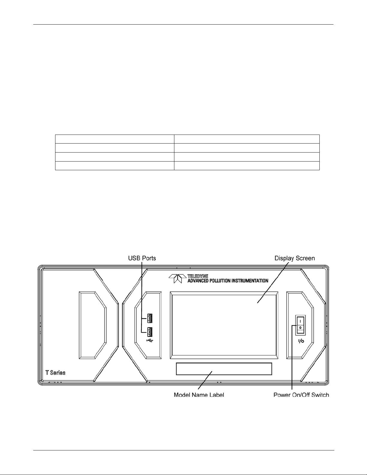
Getting Started Teledyne API - Model T200H/T200M Operation Manual
07270D DCN7141
4. Inspect the interior of the instrument to ensure all circuit boards and other
components are intact and properly seated.
5. Check the connectors of the various internal wiring harnesses and pneumatic hoses
to make sure they are firmly and properly seated.
6. Verify that all of the optional hardware ordered with the unit has been installed.
These are checked on the paperwork (Form 04490) accompanying the analyzer.
3.2. VENTILATION CLEARANCE
Whether the analyzer is set up on a bench or installed into an instrument r ack, be sure to
leave sufficient ventilation clearance.
AREA MINIMUM REQUIRED CLEARANCE
Back of the instrument 10 cm / 4 inches
Sides of the instrument 2.5 cm / 1 inch
Above and below the instrument. 2.5 cm / 1 inch
3.3. T200H/M LAYOUT
Figure 3-1 shows the front panel layout of the analyzer, and Figure 3-4 shows the rear
panel with optional zero-air scrubber mounted to it and two optional fittings for the IZS
option. Figure 3-5 shows a top-down view of the analyzer. This configuration includes
the IZS option, zero-air scrubber and an additional sample dryer (bri efly described in
Section 1.4).
26
Figure 3-1: Front Panel
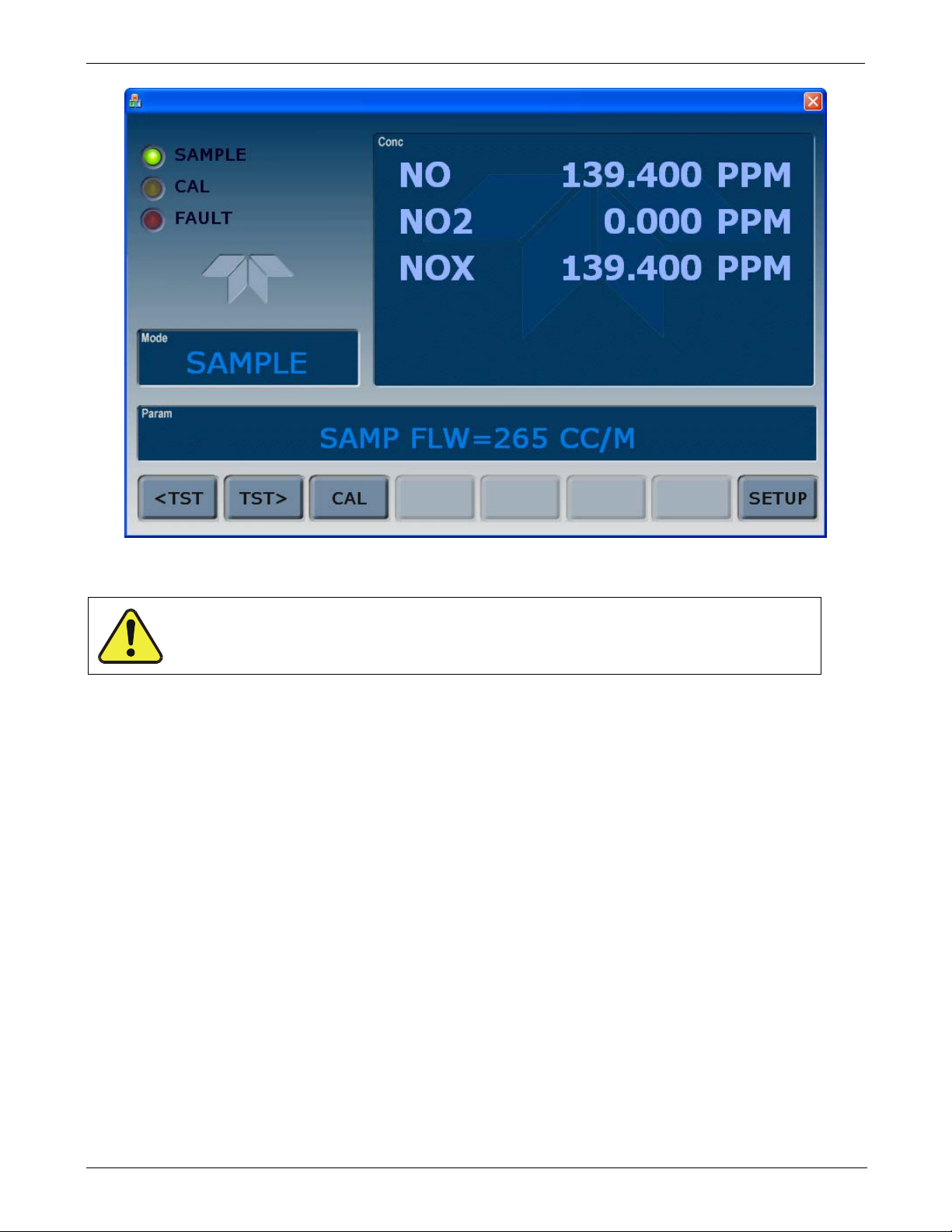
Teledyne API - Model T200H/T200M Operation Manual Getting Started
07270D DCN7141
Figure 3-2: Display Screen and Touch Control
CAUTION – Avoid Damaging Touch screen
Do not use hard-surfaced instruments such as pens to operate the touch screen.
The front panel liquid crystal display screen includes touch control. Upon analyzer startup, the screen shows a splash screen and other initialization indicators before the main
display appears, similar to Figure 3-2 above (may or may not display a Fault alarm). The
LEDs on the display screen indicate the Sample, Calibration and Fault states; also on the
screen is the gas concentration field (Conc), which displays real-time readouts for the
primary gas and for the secondary gas if instal led. The display screen also shows what
mode the analyzer is currently in, as well as messages and data (Param). Along the
bottom of the screen is a row of touch control buttons; only those that are currently
applicable will have a label. Table 3-1 provides detailed information for each component
of the screen.
27

Getting Started Teledyne API - Model T200H/T200M Operation Manual
LEDs indicating the states of Sample, Calibration and Fault, as follows:
Name
Color
State
Definition
DAS hold-off mode is ON, DAS disabled
Blinking
Unit is in calibration mode
Blinking
Warnings exist
07270D DCN7141
Table 3-1: Display Screen and Touch Control Description
Field Description/Function
Status
Off
On
SAMPLE Green
CAL Yellow
FAULT Red
Conc
Mode Displays the name of the analyzer’s current operating mode
Param
Control Buttons Displays dynamic, context sensitive labels on each button, which is blank when inactive until applicable.
Displays the actual concentration of the sample gas currently being measured by the analyzer in the
currently selected units of measure
Displays a variety of informational messages such as warning messages, operational data, test function
values and response messages during interactive tasks.
Blinking
Off
On
Off
Unit is not operating in sample mode, DAS is disabled.
Sample Mode active; Front Panel Display being updated; DAS data
being stored.
Unit is operating in sample mode, front panel display being updated,
Auto Cal disabled
Auto Cal enabled
No warnings exist
Figure 3-3 shows how the front panel display is mapped to the menu charts illustrated in
this manual. The Mode, Param (parameters), and Conc (gas concentration) fields in the
display screen are represented across the t op row of each menu chart. The eight touch
control buttons along the bottom of the display screen are represented in the bottom row
of each menu chart.
28
 Loading...