

Teledyne T200 User Manual

User Manual
Toll-free Phone:
+ 800-324-5190
Phone:
+1 858-657-9800
Fax:
+1 858-657-9816
Email:
api-sales@teledyne.com
Website:
http://www.teledyne-api.com/
Model T200
NO/NO2/NOX Analyzer
with NumaView™ software
ELEDYNE API (TAPI)
© T
9970 CARROLL CANYON ROAD
SAN DIEGO, CALIFORNIA 92131-1106
USA
Copyright 2019
Teledyne API
083730200A DCN7962
11 March 2019


NOTICE OF COPYRIGHT
© 2019 Teledyne API (TAPI). All rights reserved.
TRADEMARKS
All trademarks, registered trademarks, brand names or product names appearing in
this document are the property of their respective owners and are used herein for
identification purposes only.
083730200A DCN7962 Teledyne API T200 NO/NO2/NOx Analyzer with NumaView™ Software i
SAFETY MESSAGES
Do Not Touch: Touching some parts of the instrument without
Important safety messages are provided throughout this manual for the purpose of
avoiding personal injury or instrument damage. Please read these messages
carefully. Each safety message is associated with a safety alert symbol and is placed
throughout this manual; the safety symbols are also located inside the instrument. It
is imperative that you pay close attention to these messages, the descriptions of
which are as follows:
WARNING: Electrical Shock Hazard
HAZARD: Strong oxidizer
GENERAL WARNING/CAUTION: Read the accompanying message
for specific information.
CAUTION: Hot Surface Warning
protection or proper tools could result in damage to the part(s)
and/or the instrument.
Technician Symbol: All operations marked with this symbol are to be
performed by qualified maintenance personnel only.
Electrical Ground: This symbol inside the instrument marks the
central safety grounding point for the instrument.
CAUTION
This instrument should only be used for the purpose and in the
manner described in this manual. If you use this instrument in a
manner other than that for which it was intended, unpredictable
behavior could ensue with possible hazardous consequences.
NEVER use any gas analyzer to sample combustible gas(es)!
For Technical Assistance regarding the use and maintenance of this instrument or
any other Teledyne API product, contact Teledyne API’s Technical Support
Department:
Telephone: +1 800-324-5190
Email: api-techsupport@teledyne.com
or access any of the service options on our website at http://www.teledyne-api.com/
ii Teledyne API T200 NO/NO2/NOx Analyzer with NumaView™ Software 083730200A DCN7962
CONSIGNES DE SÉCURITÉ
AVERTISSEMENT GÉNÉRAL / MISE EN GARDE : Lire la
Ne pas toucher : Toucher à certaines parties de l’instrument
Pictogramme « technicien » : Toutes les opérations portant ce
Mise à la terre : Ce symbole à l’intérieur de l’instrument
Des consignes de sécurité importantes sont fournies tout au long du présent manuel
dans le but d’éviter des blessures corporelles ou d’endommager les instruments.
Veuillez lire attentivement ces consignes. Chaque consigne de sécurité est
représentée par un pictogramme d’alerte de sécurité; ces pictogrammes se retrouvent
dans ce manuel et à l’intérieur des instruments. Les symboles correspondent aux
consignes suivantes :
AVERTISSEMENT : Risque de choc électrique
DANGER : Oxydant puissant
consigne complémentaire pour des renseignements
spécifiques
MISE EN GARDE : Surface chaude
sans protection ou sans les outils appropriés pourrait entraîner
des dommages aux pièces ou à l’instrument.
symbole doivent être effectuées uniquement par du personnel
de maintenance qualifié.
détermine le point central de la mise à la terre sécuritaire de
l’instrument.
MISE EN GARDE
Cet instrument doit être utilisé aux fins décrites et de la
manière décrite dans ce manuel. Si vous utilisez cet instrument
d’une autre manière que celle pour laquelle il a été prévu,
l’instrument pourrait se comporter de façon imprévisible et
NE JAMAIS utiliser un analyseur de gaz pour échantillonner
entraîner des conséquences dangereuses.
des gaz combustibles!
083730200A DCN7962 Teledyne API T200 NO/NO2/NOx Analyzer with NumaView™ Software iii
WARRANTY
Failure to comply with proper anti
handling and packing instructions and Return Merchandise
Authorization (RMA) procedures when returning parts for repair or
calibration may void your warranty. For anti
packing instructions please refer to
ESD, PN 04786, in its
API’s Customer Service”
from our website at
can also be found on our website
WARRANTY POLICY (02024J)
Teledyne API (TAPI), a business unit of Teledyne Instruments, Inc., provides that:
Prior to shipment, TAPI equipment is thoroughly inspected and tested. Should
equipment failure occur, TAPI assures its customers that prompt service and support
will be available. (For the instrument-specific warranty period, please refer to the
“Limited Warranty” section in the Terms and Conditions of Sale on our website at
the following link: http://www.teledyne-api.com/terms_and_conditions.asp).
COVERAGE
After the warranty period and throughout the equipment lifetime, TAPI stands ready
to provide on-site or in-plant service at reasonable rates similar to those of other
manufacturers in the industry. All maintenance and the first level of field
troubleshooting are to be performed by the customer.
NON-TAPI MANUFACTURED EQUIPMENT
Equipment provided but not manufactured by TAPI is warranted and will be
repaired to the extent and according to the current terms and conditions of the
respective equipment manufacturer’s warranty.
PRODUCT RETURN
All units or components returned to Teledyne API should be properly packed for
handling and returned freight prepaid to the nearest designated Service Center. After
the repair, the equipment will be returned, freight prepaid.
The complete Terms and Conditions of Sale can be reviewed at
http://www.teledyne-api.com/terms_and_conditions.asp
CAUTION – Avoid Warranty Invalidation
http://www.teledyne-api.com. RMA procedures
iv Teledyne API T200 NO/NO2/NOx Analyzer with NumaView™ Software 083730200A DCN7962
-Electro-Static Discharge (ESD)
-ESD handling and
the manual, Fundamentals of
“Packing Components for Return to Teledyne
section. The manual can be downloaded
.
ABOUT THIS MANUAL
COULD DAMAGE INSTRUMENT AND VOID WARRANTY
IMPACT ON READINGS OR DATA
Provides information pertinent to the proper care,
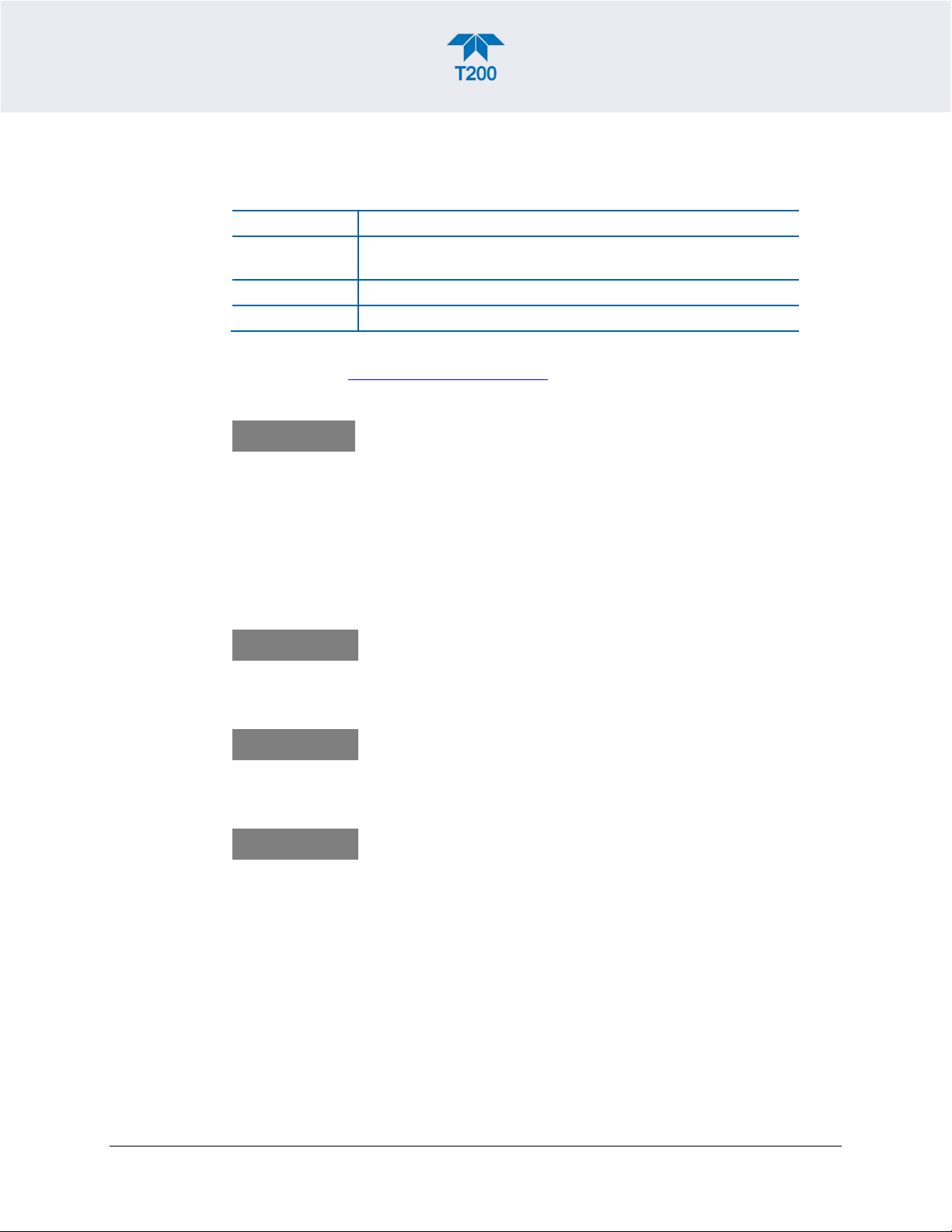
This manual is comprised of multiple documents, in PDF format, as listed below.
Part No. Name/Description
083730200 T200 NO/NO2/NOx Analyzer with NumaView™ software (this
n/a MODBUS Registers, Appendix A
069110000 T200 Interconnect Diagram, Appendix B
Support manuals, such as electrostatic discharge (ESD) prevention, are available on
the TAPI website http://www.teledyne-api.com
manual)
.
Note
CONVENTIONS USED
In addition to the safety symbols as presented in the Safety Messages page, this
manual provides special notices related to the careful and effective use of the
instrument and related, pertinent information.
ATTENTION
Important
Note
We recommend that all users read this manual in its entirety
before operating the instrument.
This special notice provides information to avoid damage
to your instrument and possibly invalidate the warranty.
Provides information about that which could either affect
accuracy of instrument readings or cause loss of data.
operation or maintenance of the instrument or its parts.
083730200A DCN7962 Teledyne API T200 NO/NO2/NOx Analyzer with NumaView™ Software v

TABLE OF CONTENTS
Safety Messages ...................................................................................................................................... ii
Warranty .................................................................................................................................................. iv
Table of Contents .................................................................................................................................... vi
List of Figures .......................................................................................................................................... xi
List of Tables .......................................................................................................................................... xiii
1. INTRODUCTION, SPECIFICATIONS, APPROVALS, & COMPLIANCE ............................................... 15
Specifications .................................................................................................................................. 15
EPA Designation ............................................................................................................................. 16
Safety .............................................................................................................................................. 16
EMC ................................................................................................................................................ 16
Other Certifications ......................................................................................................................... 17
2. GETTING STARTED .............................................................................................................................. 18
Unpacking ....................................................................................................................................... 18
Ventilation Clearance ........................................................................................................... 19
Instrument Layout ........................................................................................................................... 20
Front Panel ........................................................................................................................... 20
Rear Panel ........................................................................................................................... 21
Internal Chassis ................................................................................................................... 23
Connections and Startup ................................................................................................................. 25
Electrical Connections ......................................................................................................... 25
Connecting Power ................................................................................................. 25
Connecting Analog Inputs (Option) ....................................................................... 26
Connecting Analog Outputs ................................................................................... 27
Current Loop Analog Outputs (Option 41) Setup .................................................. 28
Connecting the Status Outputs (Digital Outputs) .................................................. 29
Connecting the Control Inputs (Digital Inputs) ....................................................... 30
Concentration Alarm Relay (Option 61) ................................................................ 31
Connecting Communications Interfaces ................................................................ 31
Pneumatic Connections ....................................................................................................... 37
Critical Tubing, Pressure, Venting and Exhaust Requirements ............................ 38
Basic Connections from Calibrator ........................................................................ 39
Connections w/Ambient Zero/Ambient Span (Z/S) Valves (OPT 50A) ................. 40
Connections w/Ambient Zero/Pressurized Span Valves (OPT 50B)..................... 42
Zero Scrubber and Internal Span Source (IZS) (OPT 50G) .................................. 44
Gas Conditioner Options ....................................................................................... 47
Pneumatic Flow Diagrams ................................................................................................... 47
Startup, Functional Checks and Calibration ........................................................................ 52
Startup ................................................................................................................... 53
Alerts: Warnings and Other Messages .................................................................. 54
Functional Checks ................................................................................................. 55
Calibration.............................................................................................................. 55
Menu Overview ............................................................................................................................... 56
Home Page .......................................................................................................................... 57
Dashboard ............................................................................................................................ 59
Alerts .................................................................................................................................... 60
Calibration ............................................................................................................................ 61
Utilities .................................................................................................................................. 62
Setup .................................................................................................................................... 62
Setup Menu: Features/Functions Configuration ............................................................................ 63
Setup>Data Logging (Data Acquisition System, DAS) ........................................................ 63
Configuring Trigger Types: Periodic ...................................................................... 65
vi Teledyne API T200 NO/NO2/NOx Analyzer with NumaView™ Software 083730200A DCN7962
Configuring Trigger Types: Conditional ................................................................ 66
Downloading DAS (Data Acquisition System) Data .............................................. 66
Setup>Events ....................................................................................................................... 67
Editing or Deleting Events ..................................................................................... 69
Using Events as Triggers for Data Logging ........................................................... 70
Setup>Dashboard ................................................................................................................ 70
Setup>AutoCal (with Valve Option) ..................................................................................... 71
Setup>Vars .......................................................................................................................... 71
Setup>Homescreen ............................................................................................................. 72
Setup>Digital Outputs .......................................................................................................... 73
Setup>Analog Outputs ......................................................................................................... 74
Manual Calibration of Voltage Range Analog Outputs .......................................... 76
Manual Adjustment of Current Range Analog Outputs ......................................... 77
Setup>Instrument ................................................................................................................. 78
Setup>Comm (Communications) ....................................................................................... 79
COM1/COM2 ....................................................................................................... 79
TCP Port1 ............................................................................................................ 80
TCP Port2 ............................................................................................................ 80
TCP Port3 ............................................................................................................ 80
Network Settings ................................................................................................. 80
Transferring Configuration to Other Instruments ............................................................................ 82
3. COMMUNICATIONS AND REMOTE OPERATION ............................................................................... 83
Data Terminal/Communication Equipment (DTE DCE) .................................................................. 83
Modes, Baud Rate and Serial Communication ............................................................................... 83
Serial Communication: RS-232 ............................................................................................ 84
Serial Communication: RS-485 (Option) ............................................................................. 84
Ethernet ........................................................................................................................................... 84
Communications Protocols ............................................................................................................. 85
MODBUS ............................................................................................................................. 85
MODBUS Com Port Configuration ........................................................................ 85
Hessen ................................................................................................................................. 87
Hessen Com Port Configuration ............................................................................ 87
Hessen Settings Configuration .............................................................................. 88
Hessen Gas List Configuration .............................................................................. 90
4. CALIBRATION ........................................................................................................................................ 91
Important Precalibration Information ............................................................................................. 91
Calibration Requirements .................................................................................................... 91
Zero Air ................................................................................................................................ 92
Calibration (Span) Gas ........................................................................................................ 92
Span Gas for Multipoint Calibration ..................................................................................... 93
Physical Range Measurements ........................................................................................... 93
Interferents ........................................................................................................................... 94
NO2 Permeation Tubes ........................................................................................................ 94
Data Recording Devices ...................................................................................................... 95
NO2 Conversion Efficiency (CE) .......................................................................................... 95
Calibration Procedures .................................................................................................................... 95
Calibration and Check Procedures for Basic Configuration ................................................ 96
Zero Calibration Check and Actual Calibration ..................................................... 97
Span Calibration Check and Actual Calibration .................................................... 97
Calibration and Check Procedures with Valve Options Installed ......................................... 98
Use of Zero/Span Valve with Remote Contact Closure ........................................ 98
Automatic Zero/Span Cal/Check (Auto Cal) ................................................................................... 99
Calibration Quality Analysis .......................................................................................................... 101
Conversion Efficiency (CE) Check ................................................................................................ 102
083730200A DCN7962 Teledyne API T200 NO/NO2/NOx Analyzer with NumaView™ Software vii

Simplified GPT Data Sheet .................................................................................. 104
EPA Protocol Calibration ............................................................................................................... 105
5. MAINTENANCE AND SERVICE .......................................................................................................... 106
Maintenance Schedule .................................................................................................................. 106
Predictive Diagnostics ................................................................................................................... 108
Operational Health Checks ........................................................................................................... 109
Software/Firmware Updates .......................................................................................................... 109
Remote Updates ................................................................................................................ 109
Manual Reload/Update Procedures ................................................................................... 110
Instrument Display Calibration (for earlier instruments)..................................................... 111
Time Zone Changes ...................................................................................................................... 112
Hardware Maintenance Procedures ............................................................................................. 113
Replacing the Sample Particulate Filter ............................................................................. 113
Changing the O3 Dryer Particulate Filter ............................................................................ 114
Changing the Ozone Cleanser Chemical .......................................................................... 115
Maintaining the External Sample Pump (Pump Pack) ....................................................... 118
Rebuilding the Pump ........................................................................................... 118
Replacing the Scrubber ....................................................................................... 118
Changing the Internal Span Gas Generator Permeation Tube ......................................... 118
Changing the External Zero Air Scrubber (OPT 86C) ....................................................... 119
Changing or Cleaning the NO2 Converter .......................................................................... 122
Cleaning the Reaction Cell ................................................................................................ 124
Servicing Critical Flow Orifices .......................................................................................... 126
Checking for Light Leaks ................................................................................................. 128
Checking for Pneumatic Leaks ........................................................................................ 129
Simple Vacuum Leak and Pump Check ............................................................ 129
Detailed Pressure Leak Check .......................................................................... 129
Performing Flow Checks/Calibrations ............................................................... 130
Service and Troubleshooting ........................................................................................................ 132
Fault Diagnosis with Alerts ................................................................................................. 133
Fault Diagnosis With Dashboard Functions ....................................................................... 136
Using the Diagnostic Signal I/O Functions ........................................................................ 137
Using the Analog Output Channels.................................................................................... 138
Using the Internal Electronic Status LEDs ......................................................................... 139
CPU Status Indicator ........................................................................................... 139
Relay PCA Watchdog and Status LEDs .............................................................. 139
Flow Problems ................................................................................................................... 141
Sample Flow is Zero or Low ................................................................................ 141
Ozone Flow is Zero or Low .................................................................................. 143
High Flow ............................................................................................................. 144
Sample Flow is Zero or Low but Analyzer Reports Correct Flow ........................ 144
Calibration Problems .......................................................................................................... 145
Negative Concentrations ..................................................................................... 145
Absence of Analyzer Response to Sample Gas ................................................. 146
Unstable Zero and Span ...................................................................................... 146
Inability to Span - Deactivated SPAN Button ...................................................... 147
Inability to Zero - Deactivated ZERO Button ....................................................... 147
Non-Linear Response .......................................................................................... 148
Discrepancy Between Analog Output and Display .............................................. 149
Discrepancy Between NO and NOX Slopes ....................................................... 149
Other Performance Problems ............................................................................................ 149
Excessive Noise .................................................................................................. 150
Slow Response .................................................................................................... 150
Auto Zero Warnings ............................................................................................. 150
viii Teledyne API T200 NO/NO2/NOx Analyzer with NumaView™ Software 083730200A DCN7962
Subsystem Check for Troubleshooting .............................................................................. 151
AC Main Power .................................................................................................... 152
DC Power Supply ................................................................................................ 152
I2C Bus ................................................................................................................. 153
LCD/Display Module ............................................................................................ 153
Relay PCA ........................................................................................................... 154
Motherboard ........................................................................................................ 154
Pressure / Flow Sensor Assembly ...................................................................... 156
CPU ..................................................................................................................... 157
RS-232 Communications ..................................................................................... 158
NO2 à NO Converter ........................................................................................ 159
Photomultiplier Tube (PMT) Sensor Module ..................................................... 161
PMT Preamplifier Board .................................................................................... 161
High Voltage Power Supply (HVPS) ................................................................. 162
PMT Temperature Control PCA ........................................................................ 163
O3 Generator ..................................................................................................... 163
Internal Span Gas Generator and Valve Options .............................................. 164
Temperature Sensor .......................................................................................... 164
Service Procedures .......................................................................................................... 165
Disk-On-Module Replacement Procedure ......................................................... 166
O3 Generator Replacement ............................................................................... 167
Sample and Ozone Dryer Replacement ............................................................ 167
PMT Sensor Hardware Calibration .................................................................... 168
Replacing the PMT, HVPS or TEC .................................................................... 170
Removing / Replacing the Relay PCA from the Instrument .............................. 173
Frequently Asked Questions ......................................................................................................... 174
Technical Assistance .................................................................................................................... 175
6. PRINCIPLES OF OPERATION ............................................................................................................ 176
Measurement Principle ................................................................................................................. 176
Chemiluminescence Creation in the Reaction Cell ............................................................ 176
Chemiluminescence Detection in the Reaction Cell .......................................................... 178
The Photo Multiplier Tube (PMT) ........................................................................ 178
Optical Filter......................................................................................................... 178
NOX and NO2 Determination .............................................................................................. 179
Auto Zero ........................................................................................................................... 180
Measurement Interferences ............................................................................................... 181
Direct Interference ............................................................................................... 182
Third Body Quenching ......................................................................................... 183
Light Leaks .......................................................................................................... 183
Reaction Cell Temperature Control ..................................................................... 183
Pneumatic Operation .................................................................................................................... 184
Sample Gas Flow ............................................................................................................... 184
Vacuum Manifold ................................................................................................. 185
Sample Gas Flow Valves and Routing ................................................................ 186
Flow Rate Control - Critical Flow Orifices .......................................................................... 186
Critical Flow Orifice .............................................................................................. 187
Locations and Descriptions of Critical Flow Orifices ........................................... 187
Ozone Gas Generation and Air Flow ................................................................................. 189
The O3 Generator ................................................................................................ 190
Ozone Generator Dry Air Supply ......................................................................... 190
Ozone Supply Air Filter ........................................................................................ 192
Ozone Destruct .................................................................................................... 192
Pneumatic Sensors ............................................................................................................ 193
Sample Pressure Sensor ..................................................................................... 193
083730200A DCN7962 Teledyne API T200 NO/NO2/NOx Analyzer with NumaView™ Software ix
Vacuum Pressure Sensor .................................................................................... 193
Sample Gas Flow Calculation ............................................................................. 194
O3 Supply Air Flow Sensor .................................................................................. 194
Electronic Operation ...................................................................................................................... 195
Overview ............................................................................................................................ 195
CPU .................................................................................................................................... 197
Motherboard ....................................................................................................................... 198
A to D Conversion ............................................................................................... 198
Sensor Inputs....................................................................................................... 198
Thermistor Interface ............................................................................................ 199
Analog Outputs .................................................................................................... 199
External Digital I/O ............................................................................................... 200
Internal Digital I/O ................................................................................................ 200
I2C Data Bus ........................................................................................................ 200
Power-Up Circuit ................................................................................................. 200
Relay PCA .......................................................................................................................... 200
Status LED’s ........................................................................................................ 203
Watchdog Circuitry .............................................................................................. 203
Valve Control ....................................................................................................... 203
Heater Control ..................................................................................................... 204
Thermocouple Inputs and Configuration Jumper (JP5) ...................................... 205
Sensor Module .............................................................................................................................. 207
Photo Multiplier Tube (PMT) ......................................................................................................... 207
PMT Preamplifier ............................................................................................................... 208
PMT Cooling System ......................................................................................................... 210
TEC Control Board .............................................................................................. 211
Pneumatic Sensor Board .............................................................................................................. 212
Power Supply/Circuit Breaker ....................................................................................................... 212
AC Power Configuration .................................................................................................... 214
AC Configuration – Standard Heaters (JP2) ....................................................... 215
AC Configuration – Heaters for Option Packages (JP6) ..................................... 216
Front Panel Touchscreen/Display Interface .................................................................................. 217
LVDS Transmitter Board .................................................................................................... 218
Front Panel Touchscreen/Display Interface PCA .............................................................. 218
Software Operation ....................................................................................................................... 218
Adaptive Filter .................................................................................................................... 219
Temperature/Pressure Compensation (TPC) .................................................................... 219
Calibration - Slope and Offset ............................................................................................ 220
Glossary ............................................................................................................................................... 221
x Teledyne API T200 NO/NO2/NOx Analyzer with NumaView™ Software 083730200A DCN7962

LIST OF FIGURES
Figure 2-1. Front Panel Layout ................................................................................................................... 20
Figure 2-2. Rear Panel Layout, Base Unit (options include additional pneumatic ports) ........................... 21
Figure 2-3. Internal Chassis Layout with IZS Option .................................................................................. 23
Figure 2-4. Internal Layout with Other Options ........................................................................................... 24
Figure 2-5. Analog In Connector ................................................................................................................. 26
Figure 2-6. Analog Output Connector ......................................................................................................... 27
Figure 2-7. Current Loop Option Installed on the Motherboard .................................................................. 28
Figure 2-8. Status Output Connector for Digital Outputs ............................................................................ 29
Figure 2-9. Energizing the Control Inputs ................................................................................................... 30
Figure 2-10. Concentration Alarm Relay ..................................................................................................... 31
Figure 2-11. Rear Panel Connector Pin-Outs for RS-232 Mode ................................................................ 32
Figure 2-12. Default Pin Assignments for CPU COM Port Connector (RS-232) ........................................ 33
Figure 2-13. Jumper and Cables for Multidrop Mode ................................................................................. 35
Figure 2-14. RS-232 Multidrop PCA Option Host/Analyzer Interconnect Diagram .................................... 36
Figure 2-15. Gas Line Connections from Calibrator – Basic Configuration ................................................ 39
Figure 2-16. Gas Line Connections from Bottled Span Gas – Basic Configuration ................................... 39
Figure 2-17. Rear Panel Layout with Z/S Valve Options (OPT 50A) .......................................................... 40
Figure 2-18. Gas Line Connections with Z/S Valves Option (OPT 50A) .................................................... 41
Figure 2-19. Rear Panel Layout with Ambient Zero/Pressurized Span Valves (OPT 50B) ........................ 42
Figure 2-20. Gas Line Connection w/Ambient Zero/Pressurized Span Valves Option (OPT 50B) ............ 43
Figure 2-21. Rear Panel Layout with Internal Span Source (IZS) (OPT 50G) ........................................... 44
Figure 2-22. Gas Line Connection w/Zero Scrubber and Internal Span Source (IZS) Option (OPT 50G) . 45
Figure 2-23. Pneumatic Connections for Precision Calibration when IZS Generator Present ................... 45
Figure 2-24. Pneumatics, Basic Configuration............................................................................................ 48
Figure 2-25. Pneumatics with Zero/Span Valves Option (OPT 50A) .......................................................... 49
Figure 2-26. Pneumatics with Ambient Zero/Pressurized Span Valves (OPT 50B) .................................. 50
Figure 2-27. Pneumatics with the Internal Span Gas Generator Option (OPT 50G).................................. 51
Figure 2-28. Pneumatics for Sample Conditioner Option (OPT 86A) ......................................................... 52
Figure 2-29. Status Screens at Startup ....................................................................................................... 53
Figure 2-30. Home Page Example .............................................................................................................. 53
Figure 2-31. Viewing Active Alerts Page ..................................................................................................... 54
Figure 2-32. Sample Dashboard Page ....................................................................................................... 55
Figure 2-33. User Interface Orientation ...................................................................................................... 57
Figure 2-34. Concentration and Stability Graph (top) and Meter Graph (bottom) ...................................... 58
Figure 2-35. Dashboard Page ..................................................................................................................... 59
Figure 2-36. Navigating to the Active Alerts Page ...................................................................................... 60
Figure 2-37. Active Alerts Cleared .............................................................................................................. 61
Figure 2-38. Utilities>Alerts Log of Active and Past Alerts and Events ...................................................... 61
Figure 2-39. Datalog Configuration, New Log Page ................................................................................... 63
Figure 2-40. Datalog Configuration, Existing Log ....................................................................................... 63
Figure 2-41. Creating a New Data Log ....................................................................................................... 64
Figure 2-42. Datalog Periodic Trigger Configuration .................................................................................. 65
Figure 2-43. Datalog - Conditional Trigger Configuration ........................................................................... 66
Figure 2-44. DAS Download Page .............................................................................................................. 66
Figure 2-45. Events List .............................................................................................................................. 67
Figure 2-46. Event Configuration ................................................................................................................ 68
Figure 2-47. Configured Event Sample ....................................................................................................... 69
Figure 2-48. Edit or Delete an Event ........................................................................................................... 69
Figure 2-49. Dashboard Display and Configuration .................................................................................... 70
Figure 2-50. Homescreen Configuration ..................................................................................................... 72
Figure 2-51. Digital Outputs Setup .............................................................................................................. 73
Figure 2-52. Analog Output Configuration Example ................................................................................... 74
083730200A DCN7962 Teledyne API T200 NO/NO2/NOx Analyzer with NumaView™ Software xi

Figure 2-53. Analog Outputs Group Calibration Screen ............................................................................. 75
Figure 2-54. Analog Outputs Manual Calibration Screen (AOUT2 Example) ............................................. 75
Figure 2-55. Setup for Checking / Calibrating DCV Analog Output Signal Levels ..................................... 76
Figure 2-56. Setup for Checking / Calibration Current Output Signal Levels ............................................. 77
Figure 2-57. Alternative Setup Using 250Ω Resistor for Checking Current Output Signal Levels ............. 78
Figure 2-58. Communications Configuration, Network Settings ................................................................. 80
Figure 2-59. Configuration Transfer ............................................................................................................ 82
Figure 3-1. MODBUS via Ethernet .............................................................................................................. 85
Figure 3-2. MODBUS via Serial Communication (example) ....................................................................... 86
Figure 3-3. Serial Communication, Setting Hessen Protocol ...................................................................... 87
Figure 3-4. Hessen Gas List Configuration ................................................................................................. 90
Figure 4-1. Multi-Point Calibration Page ..................................................................................................... 96
Figure 4-2. Zero and Span Calibration Screens ......................................................................................... 98
Figure 4-3. Auto Cal Page........................................................................................................................... 99
Figure 5-1: Report Generation Page ......................................................................................................... 109
Figure 5-2. Remote Update Page ............................................................................................................. 110
Figure 5-3. Manual Update Page (and other utilities) ............................................................................... 110
Figure 5-4. Touchscreen Calibration Page ............................................................................................... 111
Figure 5-5. Time Zone Change Requirements ......................................................................................... 112
Figure 5-6. Replacing the Particulate Filter............................................................................................... 113
Figure 5-7. Particle Filter on O3 Supply Air Dryer ..................................................................................... 115
Figure 5-8. Ozone Cleanser Assembly ..................................................................................................... 116
Figure 5-9. Zero Air Scrubber Assembly ................................................................................................... 121
Figure 5-10. NO2 Converter Assembly...................................................................................................... 123
Figure 5-11. Reaction Cell Assembly ........................................................................................................ 125
Figure 5-12. Critical Flow Orifice Assembly .............................................................................................. 126
Figure 5-13. Flow Calibration Menu .......................................................................................................... 131
Figure 5-14. CPU Status Indicator ............................................................................................................ 139
Figure 5-15. Relay PCA Status LEDS Used for Troubleshooting ............................................................. 140
Figure 5-16. Location of DC Power Test Points on Relay PCA ................................................................ 153
Figure 5-17. Typical Set Up of Status Output Test ................................................................................... 155
Figure 5-18. Pressure / Flow Sensor Assembly........................................................................................ 156
Figure 5-19. Pre-Amplifier Board Layout .................................................................................................. 169
Figure 5-20. Sensor Assembly .................................................................................................................. 171
Figure 5-21. Relay PCA with AC Relay Retainer In Place ........................................................................ 173
Figure 5-22. Relay PCA Mounting Screw Locations ................................................................................. 173
Figure 6-1. Reaction Cell with PMT Tube and Optical Filter ..................................................................... 178
Figure 6-2. Sensitivity Spectrum ............................................................................................................... 179
Figure 6-3. NO2à NO Conversion ............................................................................................................ 179
Figure 6-4. Pneumatic Flow during the Auto Zero Cycle .......................................................................... 181
Figure 6-5. Vacuum Manifold, Standard Configuration ............................................................................. 185
Figure 6-6. Flow Control Assembly & Critical Flow Orifice ....................................................................... 187
Figure 6-7. Location of Flow Control Assemblies & Critical Flow Orifices ................................................ 188
Figure 6-8. Ozone Generator Principle ..................................................................................................... 190
Figure 6-9. Semi-Permeable Membrane Drying Process ......................................................................... 191
Figure 6-10. Sample Dryer ........................................................................................................................ 191
Figure 6-11. Electronic Block Diagram ..................................................................................................... 195
Figure 6-12. CPU Board ............................................................................................................................ 197
Figure 6-13. Relay PCA Layout (P/N 045230100) .................................................................................... 201
Figure 6-14. Relay PCA P/N 045230100 with AC Relay Retainer in Place .............................................. 202
Figure 6-15. Heater Control Loop Block Diagram. .................................................................................... 205
Figure 6-16. Thermocouple Configuration Jumper (JP5) Pin-Outs .......................................................... 206
Figure 6-17. Basic PMT Design ................................................................................................................ 207
Figure 6-18. PMT Preamp Block Diagram ................................................................................................ 209
xii Teledyne API T200 NO/NO2/NOx Analyzer with NumaView™ Software 083730200A DCN7962

Figure 6-19. Typical Thermo-Electric Cooler ............................................................................................ 210
Figure 6-20. PMT Cooling System Block Diagram ................................................................................... 211
Figure 6-21. Power Distribution Block Diagram ........................................................................................ 213
Figure 6-22. Location of AC power Configuration Jumpers ...................................................................... 214
Figure 6-23. Typical Set Up of AC Heater Jumper Set (JP2) ................................................................... 215
Figure 6-24. Typical Jumper Set (JP2) Set Up of Heaters ...................................................................... 216
Figure 6-25. Front Panel and Display Interface Block Diagram ................................................................ 217
Figure 6-26. Basic Software Operation ..................................................................................................... 218
LIST OF TABLES
Table 1-1. Specifications ............................................................................................................................. 15
Table 2-1. Ventilation Clearance ................................................................................................................. 19
Table 2-2. Rear Panel Description .............................................................................................................. 22
Table 2-3. Analog Input Pin Assignments ................................................................................................... 26
Table 2-4. Analog Output Pin Assignments ................................................................................................ 27
Table 2-5. Status Output Pin Assignments ................................................................................................. 30
Table 2-6. Control Input Pin Assignments .................................................................................................. 31
Table 2-7. Zero/Span Valves Operating States (OPT 50A) ........................................................................ 49
Table 2-8. Ambient Zero/Pressurized Span Valve Operating States (OPT 50B) ....................................... 50
Table 2-9. IZS Valve Option Operating States (OPT 50G) ......................................................................... 51
Table 2-10. Menu Overview ........................................................................................................................ 56
Table 2-11. Utilities Submenu Descriptions ................................................................................................ 62
Table 2-12. List of Variables with Descriptions ........................................................................................... 71
Table 2-13. Analog Output Voltage/Current Range .................................................................................... 75
Table 2-14. Voltage Tolerances .................................................................................................................. 76
Table 2-15. Current Loop Output Check ..................................................................................................... 78
Table 2-16. Setup>Instrument Menu .......................................................................................................... 78
Table 2-17. COM1/COM2 Configuration ..................................................................................................... 79
Table 2-18. LAN/Ethernet Configuration Properties ................................................................................... 81
Table 3-1. Ethernet Status Indicators ......................................................................................................... 84
Table 3-2. Teledyne API's Hessen Protocol Response Modes .................................................................. 88
Table 3-3. Hessen Status Flags and Default Bit Assignments ................................................................... 89
Table 3-4. Hessen Gas List Definitions ....................................................................................................... 90
Table 4-1. AUTO CAL States .................................................................................................................... 100
Table 4-2. Auto Cal Setup Combinations .................................................................................................. 100
Table 4-3. Auto Cal Programming Sequence Execution .......................................................................... 101
Table 4-4. Calibration Data Quality Evaluation ......................................................................................... 102
Table 5-1. Maintenance Schedule ............................................................................................................ 107
Table 5-2. Predictive Uses for Dashboard Functions ............................................................................... 108
Table 5-3. Warning Alerts, Fault Conditions and Possible Causes .......................................................... 133
Table 5-4. Dashboard Functions - Indicated Failures ............................................................................... 137
Table 5-5. Analog Outputs as Diagnostic Tools....................................................................................... 138
Table 5-6. Relay PCA Watchdog and Status LED Failure Indications ..................................................... 140
Table 5-7. DC Power Test Point and Wiring Color Codes ........................................................................ 152
Table 5-8. DC Power Supply Acceptable Levels ...................................................................................... 153
Table 5-9. Relay PCA Control Devices ..................................................................................................... 154
Table 5-10. Control Input Pin Assignments and Corresponding Signal I/O Functions ............................. 155
Table 6-1. List of Interferents .................................................................................................................... 181
Table 6-2. Valve Cycle Phases ................................................................................................................ 186
Table 6-3. Gas Flow Controls ................................................................................................................... 188
Table 6-4. Relay PCA Status LED’s ......................................................................................................... 203
Table 6-5. Thermocouple Configuration Jumper (JP5) Pin-Outs .............................................................. 206
Table 6-6. Power Configuration for Standard AC Heaters (JP2) .............................................................. 215
Table 6-7. Power Configuration for Optional Heaters (JP6) ..................................................................... 216
083730200A DCN7962 Teledyne API T200 NO/NO2/NOx Analyzer with NumaView™ Software xiii

Appendix A – MODBUS Registers
Appendix B – Interconnect Wiring Diagram
xiv Teledyne API T200 NO/NO2/NOx Analyzer with NumaView™ Software 083730200A DCN7962

1. INTRODUCTION, SPECIFICATIONS, APPROVALS, &
PARAMETER
SPECIFICATION
Min/Max Range
Span Drift
< 0.5% of Full Scale (at constant temperature and voltage) /24 hours
AC Power
Rating
220-240 V~, 50/60 Hz, 3.0 A
Typical Power Consumption
110 W
10V, 5V, 1V, 0.1V (selectable)
All Ranges with 5% Under/Over Range
Analog Output Resolution
1 part in 4096 of selected full-scale voltage
Recorder Offset
COMPLIANCE
Teledyne API’s Model T200 (also referred to as T200) NO/NO2/NOX Analyzer uses
chemiluminescence detection (see Principles of Operation, Section 6, this manual),
coupled with state-of-the-art microprocessor technology to provide the sensitivity, stability
and ease of use needed for ambient or dilution CEM monitoring requirements of nitric
oxide (NO), nitrogen dioxide (NO
high accuracy and dependability, the T200 tracks operational parameters and issues
warnings if they fall outside diagnostic limits, as well as stores easily retrievable data.
Proprietary software allows configurable data acquisition capability that can be triggered
conditionally or periodically, enabling operators to perform predictive diagnostics and
enhanced data analysis by tracking parameter trends. Reports can be downloaded onto a
USB flash drive or via the I/O ports. Operators can also view real-time graphing with one
touch of the interface screen.
) and total nitrogen oxides (NOx). Along with providing
2
SPECIFICATIONS
Table 1-1. Specifications
(Physical Analog Output)
Measurement Units ppb, ppm, µg/m3, mg/m3 (selectable)
Zero Noise1 < 0.2 ppb (RMS)
Span Noise1 < 0.5% of reading (RMS) above 50 ppb
Lower Detectable Limit 2 0.4 ppb
Zero Drift < 0.5 ppb (at constant temperature and voltage) /24 hours
Lag Time
Rise/Fall Time1 < 60 seconds to 95%
Linearity 1% of full scale
Precision 0.5% of reading above 50 ppb
Sample Flow Rate 500 cc/min ± 10%
1
Min: 0-50 ppb Full Scale
Max: 0-20,000 ppb Full Scale (selectable, dual ranges supported)
20 seconds
110-120 V~, 60 Hz, 3.0 A
100 W
Analog Output Ranges
± 10%
083730200A DCN7962 Teledyne API T200 NO/NO2/NOx Analyzer with NumaView™ Software 15

PARAMETER
SPECIFICATION
Standard I/O
1 Ethernet: 10/100Base-T
2 RS-232 (300 – 115,200 baud)
4 analog outputs
3 4-20mA current outputs
Environmental Conditions
Installation Category (Over voltage Category) II Pollution Degree 2
Intended for Indoor Use Only at Altitudes ≤ 2000m
2 USB device ports
8 opto-isolated digital status outputs (7 defined, 1 spare)
6 opto-isolated digital control inputs (4 defined, 2 spare)
Optional I/O 1 USB com port
1 RS485
8 analog inputs (0-10V, 12-bit)
4 digital alarm outputs
Multidrop RS232
Dimensions H x W x D 7" x 17" x 23.5" (178mm x 432 mm x 597 mm)
Weight Analyzer: 40 lbs (18 kg)
External Pump Pack: 15 lbs (7 kg)
Operating Temperature Range
Humidity Range 0-95% RH non-condensing
1
As defined by the US EPA.
2
Defined as twice the zero noise level by the US EPA.
All specifications are based on constant conditions.
5 - 40 °C (with US EPA approval)
EPA DESIGNATION
Teledyne API’s Model T200 nitrogen oxides analyzer is officially designated as US EPA
Federal Reference Method (FRM), Designation Number RFNA-1194-099. The official
List of Designated Reference and Equivalent Methods is published in the U.S. Federal
Register
and configurations.
– http://www3.epa.gov/ttn/amtic/criteria.html, and specifies the instrument’s settings
SAFETY
IEC/EN 61010-1:2010 (3rd Edition), Safety requirements for electrical equipment for
measurement, control, and laboratory use.
CE: 2006/95/EC, Low-Voltage Directive
EMC
IEC/EN 61326-1, Class A Emissions/Industrial Immunity
FCC 47 CFR Part 15B, Class A Emissions
CE: 2004/108/EC, Electromagnetic Compatibility Directive
16 Teledyne API T200 NO/NO2/NOx Analyzer with NumaView™ Software 083730200A DCN7962

OTHER CERTIFICATIONS
EU: EN14211 TÜV Rheinland
QAL1 Certified: EN15267
MCerts: Sira MC050068/11
083730200A DCN7962 Teledyne API T200 NO/NO2/NOx Analyzer with NumaView™ Software 17
2. GETTING STARTED
To avoid personal injury, always use two persons to lift and
COULD DAMAGE INSTRUMENT AND VOID WARRANTY
COULD DAMAGE INSTRUMENT AND VOID WARRANTY
Note
materials for future use if/when the instrument should be
api.com.
This section addresses unpacking, connecting, and initializing the instrument, getting an
overview of the menu system, and setting up/configuring the functions.
UNPACKING
carry the analyzer.
ATTENTION
CAUTION - GENERAL SAFETY HAZARD
Printed Circuit Assemblies (PCAs) are sensitive to electro-static
discharges too small to be felt by the human nervous system. Failure
to use Electro-Static Discharge (ESD) protection when working with
electronic assemblies will void the instrument warranty. Refer to the
manual, Fundamentals of ESD, PN 04786, which can be downloaded
from our website at http://www.teledyne-api.com
.
ATTENTION
Do not operate this instrument without first removing dust plugs from
SAMPLE and EXHAUST ports on the rear panel.
Teledyne API recommends that you store shipping containers
and
returned to the factory for repair and/or calibration service. See
Warranty statement in this manual and Return Merchandise
Authorization (RMA) on our Website at
http://www.teledyne-
Verify that there is no apparent external shipping damage. If damage has occurred, please
advise the shipper first, then Teledyne API.
Included with your instrument is a printed record of the final performance characterization
performed on your instrument at the factory. This record, titled Final Test and Validation
Data Sheet, is an important quality assurance and calibration record and should be placed
in the quality records file for this instrument.
18 Teledyne API T200 NO/NO2/NOx Analyzer with NumaView™ Software 083730200A DCN7962
AREA
MINIMUM REQUIRED CLEARANCE
10 cm / 4 in
2.5 cm / 1 in
With no power to the unit, carefully remove the top cover of the instrument and check for
internal shipping damage by carrying out the following steps:
1. Carefully remove the top cover and check for internal shipping damage.
a. Remove the screws located on the instrument’s sides.
b. Slide the cover backward until it clears the instrument’s front bezel.
c. Lift the cover straight up.
2. Inspect the interior of the instrument to ensure all circuit boards and other
components are intact and securely seated.
3. Check the connectors of the various internal wiring harnesses and
pneumatic hoses to ensure they are firmly and securely seated.
4. Verify that all of the optional hardware ordered with the unit has been
installed. These are listed on the paperwork accompanying the instrument.
WARNING – ELECTRICAL SHOCK HAZARD
Never disconnect PCAs, wiring harnesses or electronic
subassemblies while under power.
VENTILATION CLEARANCE
Whether the instrument is set up on a bench or installed in a rack, be sure to leave sufficient
ventilation clearance.
Table 2-1. Ventilation Clearance
Back of the instrument
Sides of the instrument 2.5 cm / 1 in
Above and below the instrument
083730200A DCN7962 Teledyne API T200 NO/NO2/NOx Analyzer with NumaView™ Software 19
INSTRUMENT LAYOUT
Instrument layout includes front panel, rear panel connectors, and the internal chassis layout.
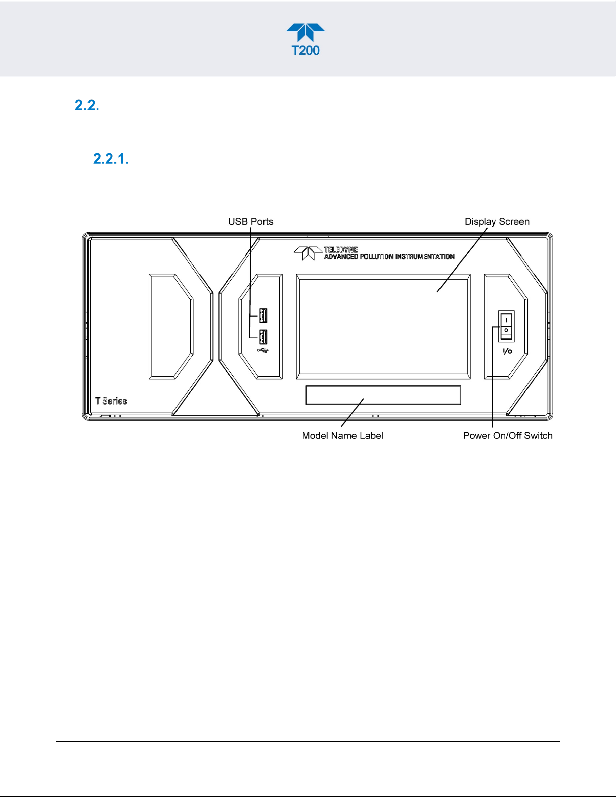
FRONT PANEL
The front panel (Figure 2-1) includes two USB ports for peripheral device connections,
which can be used with mouse and keyboard as alternatives to the touchscreen interface,
or with flash drive for uploads/downloads (devices not included).
Figure 2-1. Front Panel Layout
20 Teledyne API T200 NO/NO2/NOx Analyzer with NumaView™ Software 083730200A DCN7962
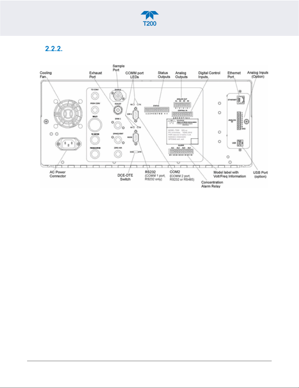
REAR PANEL
Figure 2-2 shows the layout of the rear panel.
Figure 2-2. Rear Panel Layout, Base Unit (options include additional pneumatic ports)
083730200A DCN7962 Teledyne API T200 NO/NO2/NOx Analyzer with NumaView™ Software 21

Table 2-2. Rear Panel Description
TO CONV
CONTROL IN
COMPONENT FUNCTION
cooling fan
AC power
connector
Model/specs label
Pulls ambient air into chassis through side vents and exhausts through rear.
Connector for three-prong cord to apply AC power to the analyzer.
CAUTION! The cord’s power specifications (specs) MUST comply with the power
specs on the analyzer’s rear panel Model number label
Identifies the analyzer model number and provides power specs
(not used)
FROM CONV
MULTI
TO DRYER
FROM DRYER
SAMPLE
EXHAUST
SPAN 1
SPAN2/VENT
ZERO AIR
RX TX
COM 2
RS-232
DCE DTE
STATUS
ANALOG OUT
(not used)
(not used)
(not used)
Outlet for internal sample gas dryer; connect to external zero air scrubber (for IZS options
only).
Connect a gas line from the source of sample gas here.
Calibration gases can also enter here on units without zero/span/shutoff valve options
installed.
Connect an exhaust gas line of not more than 10 meters long here that leads outside the
shelter or immediate area surrounding the instrument. The line must be ¼” tubing or
greater.
On units with zero/span/shutoff valves option installed, connect a gas line to the source of
calibrated span gas here.
On units with pressurized span valve option, used for venting.
Internal Zero Air: On units with zero/span/shutoff valves option installed but no internal zero
air scrubber attach a gas line to the source of zero air here.
LEDs indicate receive (RX) and transmit (TX) activity on the when blinking.
Serial communications port for RS-232 or RS-485.
Serial communications port for RS-232 only.
Switch to select either data terminal equipment or data communication equipment during
RS-232 communication.
For outputs to devices such as Programmable Logic Controllers (PLCs).
For voltage or current loop outputs to a strip chart recorder and/or a data logger.
For remotely activating the zero and span calibration modes.
ALARM
ETHERNET
ANALOG IN
USB
Model Label
Option for concentration alarms and system warnings.
Connector for network or Internet remote communication, using Ethernet cable
Option for external voltage signals from other instrumentation and for logging these signals
Connector for direct connection to laptop computer, using USB cable.
Includes voltage and frequency specifications
22 Teledyne API T200 NO/NO2/NOx Analyzer with NumaView™ Software 083730200A DCN7962
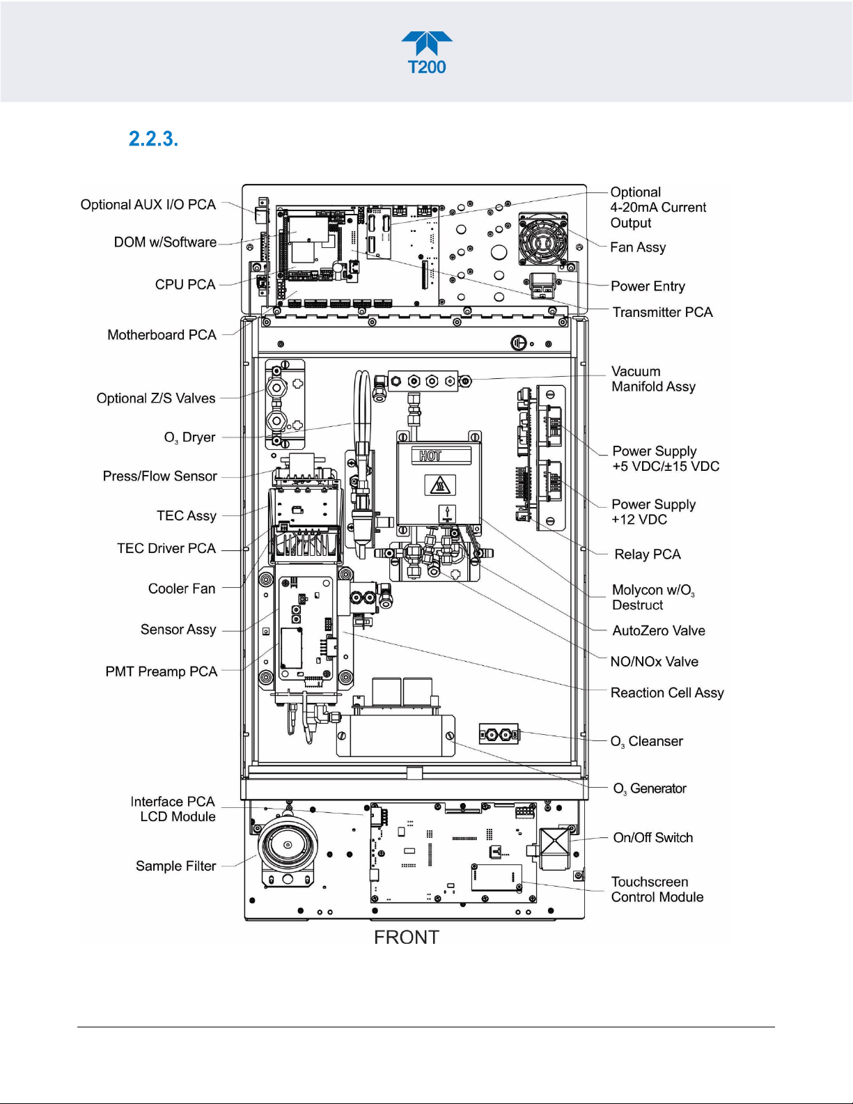
INTERNAL CHASSIS
Figure 2-3 and Figure 2-4 show internal chassis configurations with different options.
Figure 2-3. Internal Chassis Layout with IZS Option
083730200A DCN7962 Teledyne API T200 NO/NO2/NOx Analyzer with NumaView™ Software 23
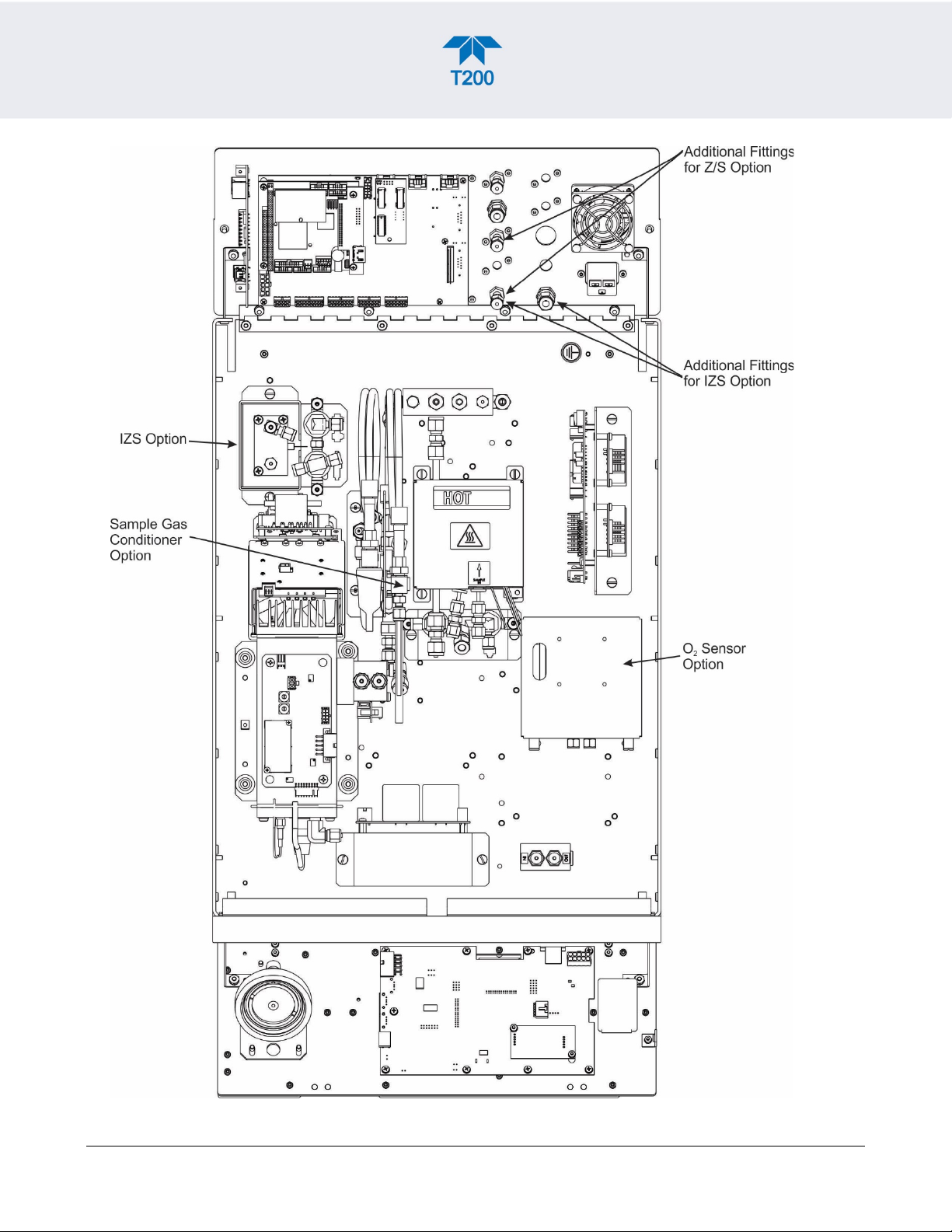
Figure 2-4. Internal Layout with Other Options
24 Teledyne API T200 NO/NO2/NOx Analyzer with NumaView™ Software 083730200A DCN7962
CONNECTIONS AND STARTUP
To maintain compliance with EMC standards, cable length
Do not operate with cover off.
This section presents the electrical (Section 2.3.1) and pneumatic (Section 2.3.2)
connections for setting up and preparing the instrument for operation (Section 2.3.3).
ELECTRICAL CONNECTIONS
Note
must be go greater than 3 meters for all I/O connections.
WARNING – Electrical Shock Hazard
• High Voltages are present inside the instrument’s case.
• Power connection must have functioning ground connection.
• Do not defeat the ground wire on power plug.
• Turn off instrument power before disconnecting or connecting
electrical subassemblies.
•
CAUTION – Avoid Damage to the Instrument
Ensure that the AC power voltage matches the voltage indicated on
the instrument’s model/specs label before plugging it into line
power.
CONNECTING POWER
Attach the power cord between the instrument’s AC power connector and a power outlet
capable of carrying at least the rated current at your AC voltage range and ensure that it is
equipped with a functioning earth ground. It is important to adhere to all safety and
cautionary messages.
083730200A DCN7962 Teledyne API T200 NO/NO2/NOx Analyzer with NumaView™ Software 25
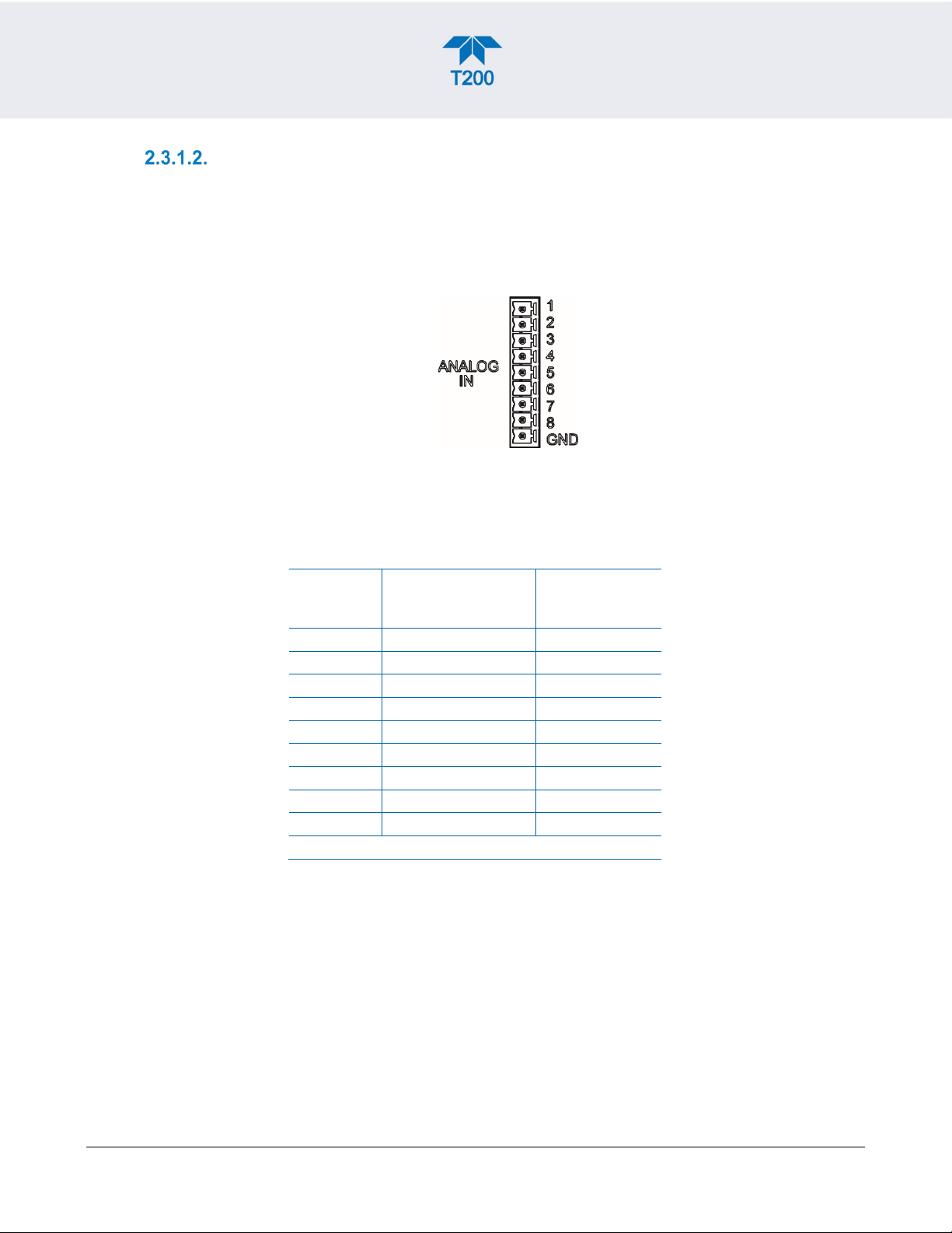
CONNECTING ANALOG INPUTS (OPTION)
DAS/DATA
PARAMETER1
3
Analog input # 3
Channel 3
The Analog In connector option is used for measuring external voltage signals from other
instrumentation (such as meteorological instruments) and for logging these signals in the
analyzer’s internal data acquisition system, the Data Logger (Section 2.5.1). The input
voltage range for each analog input is 0-10 VDC and input impedance is nominally 20kΩ
in parallel with 0.1µF.
Figure 2-5. Analog In Connector
Assignments for the Analog In connector pins 1 through 8 (Table 2-3) are configurable
through the Setup>Ext Analog Inputs menu (visible with installed option).
Table 2-3. Analog Input Pin Assignments
PIN DESCRIPTION
1 Analog input # 1 Channel 1
2 Analog input # 2 Channel 2
4 Analog input # 4 Channel 4
5 Analog input # 5 Channel 5
6 Analog input # 6 Channel 6
7 Analog input # 7 Channel 7
8 Analog input # 8 Channel 8
GND Analog input Ground N/A
1
See Section 2.5.1 to set up the Data Logger.
LOGGER
26 Teledyne API T200 NO/NO2/NOx Analyzer with NumaView™ Software 083730200A DCN7962
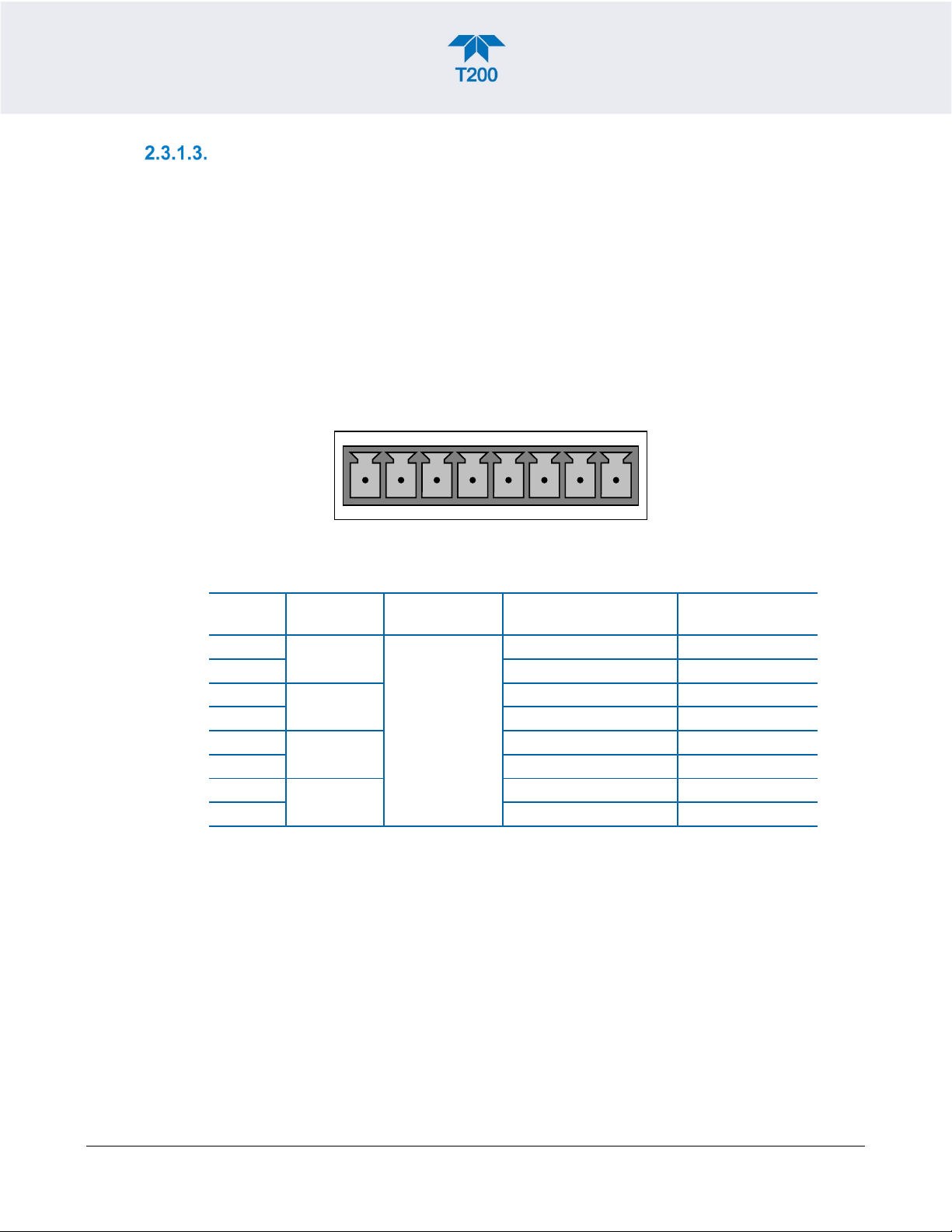
CONNECTING ANALOG OUTPUTS
ANALOG OUT
A1 A2 A3 A4
+ - + - + - + -
ANALOG
OUTPUT
STANDARD
VOLTAGE OUTPUT
CURRENT
LOOP OPTION
The rear panel Analog Output channels A1 through A4 can be mapped to reflect various
operating values in the analyzer, including concentration values, temperatures, pressures,
etc. These mappings are not configured by default and must be set by the user.
An optional Current Loop output (Section 2.3.1.4) is available for A1, A2 and A3 only.
To access these signals attach a strip chart recorder and/or data-logger to the appropriate
analog output connections on the rear panel of the analyzer.
Configure through the Setup>Analog Outputs menu (Section 2.5.8)
Figure 2-6. Analog Output Connector
Table 2-4. Analog Output Pin Assignments
PIN
1
2 Ground I Out 3
4 Ground I Out 3
4 Ground I Out 7
8 Ground Not Available
A1
A2
A3
A4
SIGNAL OUT
User-selected
through the
Setup>Analog
Outputs menu.
V + I Out +
V + I Out +
V + I Out +
V + Not Available
083730200A DCN7962 Teledyne API T200 NO/NO2/NOx Analyzer with NumaView™ Software 27
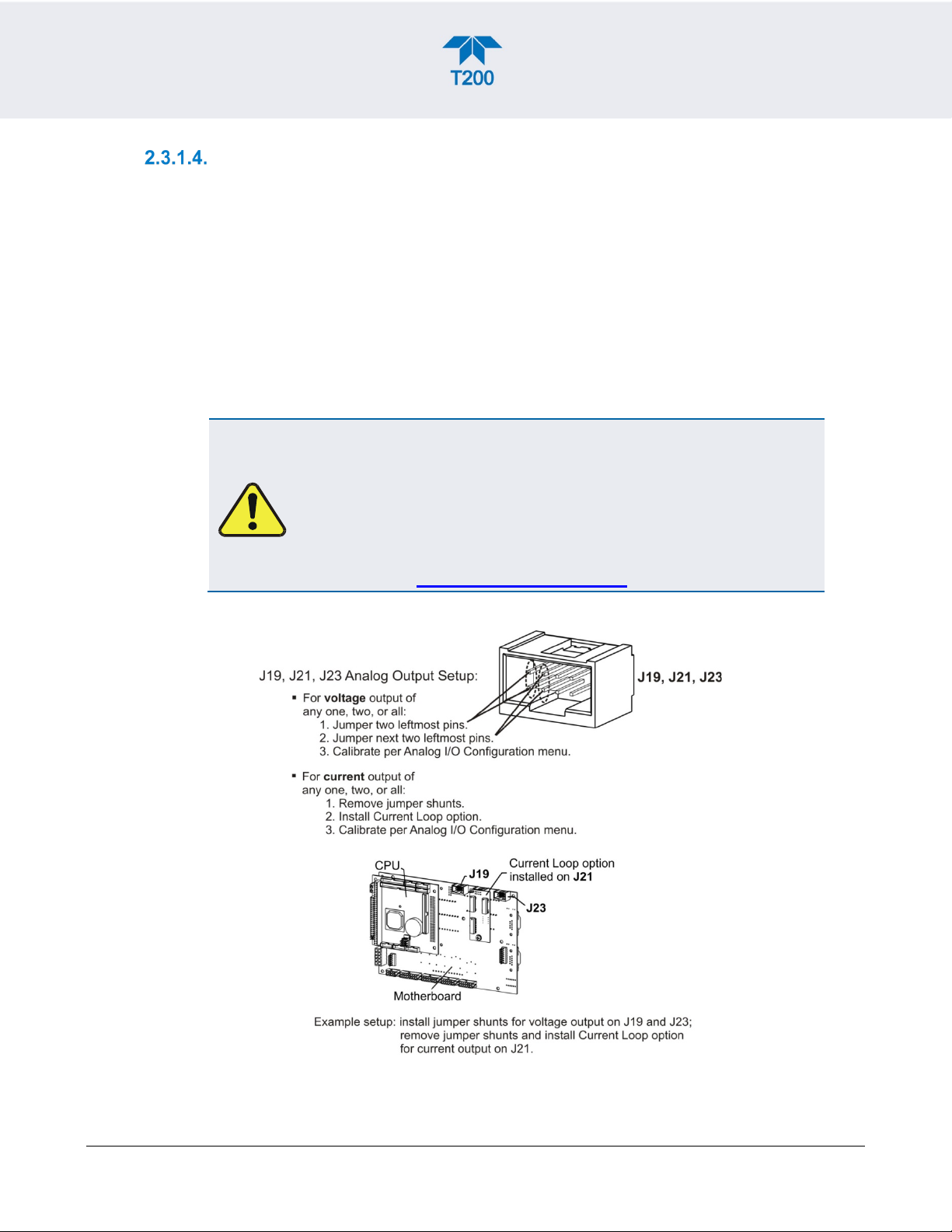
CURRENT LOOP ANALOG OUTPUTS (OPTION 41) SETUP
our website at http://www.teledyne-api.com.
If your analyzer had this option installed at the factory, there are no further connections to
be made. Otherwise, it can be installed as a retrofit for each of the analog outputs. This
option converts the DC voltage analog output to a current signal with 0-20 mA output
current, which can be scaled to any set of limits within that 0-20 mA range. However, most
current loop applications call for either 2-20 mA or 4-20 mA range. All current loop outputs
have a +5% over-range. Ranges with the lower limit set to more than 1 mA (e.g., 2-20 or
4-20 mA) also have a -5% under-range.
Figure 2-7 provides installation instructions and illustrates a sample configuration of one
current output combined with two voltage outputs. Next are instructions for converting
current loop analog outputs to standard 0-to-5 VDC outputs. To calibrate or adjust these
outputs use the Setup>Analog Outputs menu (Section 2.5.8).
CAUTION – Avoid Invalidating Warranty
Servicing or handling of circuit components requires electrostatic
discharge protection, i.e. ESD grounding straps, mats and
containers. Failure to use ESD protection when working with
electronic assemblies will void the instrument warranty. For
information on preventing ESD damage, refer to the manual,
Fundamentals of ESD, PN 04786, which can be downloaded from
Figure 2-7. Current Loop Option Installed on the Motherboard
28 Teledyne API T200 NO/NO2/NOx Analyzer with NumaView™ Software 083730200A DCN7962
 Loading...