

Teledyne t100, t108u, t100h, t108, t100u Operation Manual

Also supports operation of:
when used in conjunction with:
Model T100U Analyzer
T100U addendum, PN 06840
Model T100H Analyzer
T100H addendum, PN 07265
Model T108 Analyzer
T108 addendum, PN 07268
T108 addendum, PN 07268
Operation Manual
Model T100
UV Fluorescence SO2 Analyzer
Model T108U Analyzer
T100U addendum, PN 06840, and
© TELEDYNE API (TAPI)
9970 CARROLL CANYON ROAD
SAN DIEGO, CA 92131-1106
USA
Toll-free Phone: 800-324-5190
Phone: +1 858-657-9800
Fax: +1 858-657-9816
Email: api-sales@teledyne.com
Website: http://www.teledyne-api.com/
Copyright 2010-2016
Teledyne API 05 August 2016
06807F DCN7335


06807F DCN7335
NOTICE OF COPYRIGHT
© 2010-2016 Teledyne API Inc. All rights reserved.
TRADEMARKS
All trademarks, registered trademarks, brand names or product names appea ring in thi s
document are the property of their respective owners and are used herein for
identification purposes only.
i
Teledyne API - T100 UV Fluorescenc e SO2 Analyzer
and/or the instrument.
06807F DCN7335
IMPORTANT SAFETY INFORMATION
Important safety messages are provided throughout this manual for the purpose of
avoiding personal injury or instrument damage. Please read these messages carefully.
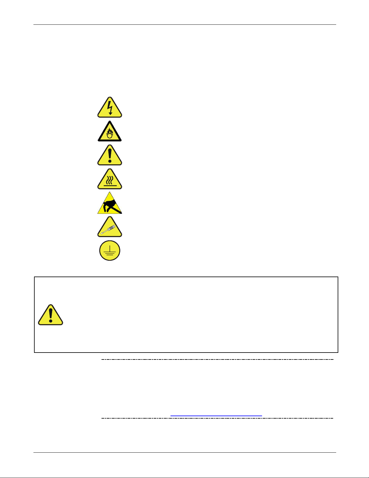
Each safety message is associated with a safety alert symbol and placed throughout this
manual and inside the instrument. The symbols with messages are defined as follows:
WARNING: Electrical Shock Hazard
HAZARD: Strong oxidizer
GENERAL WARNING/CAUTION: Read the accompanying
message for s pecifi c information.
CAUTION: Hot Surface Warning
Note
Do Not Touch: Touching some parts of the instrument without
protection or proper tools could result in damage to the part(s)
Technician Symbol: All operations marked with this symbol are
to be performed by qualified maintenance personnel only.
Electrical Ground: This symbol inside the instrument marks the
central safety grounding point for the instrument.
CAUTION
GENER AL S AFETY HAZARD
The T100 Analyzer should only be used for the purpose and in the
manner described in this manual. If you use the T100 in a manner other
than that for which it was intended, unpredictable behavior could ensue
with possible hazardous consequences.
NEVER use any gas analyzer to sample combustible gas(es).
Technical Assistance regarding the use and maintenance of the T100 or
any other Teledyne API product can be obtained by contacting Teledyne
API’s Technical Support Department:
Phone: 800-324-5190
Email: sda_techsupport@teledyne.com
or by accessing various service options on our website at
http://www.teledyne-api.com/
.
ii

AVERTISSEMENT : Risque de choc électrique
DANGER : Oxydant puissant
AVERTISSEMENT GÉNÉRAL / MISE EN GARDE : Lire la consigne
MISE EN GARDE : Surface chaude
Ne pas toucher
Mise à la terre : Ce symbole à l’intérieur de l’instrument détermine le point central
06807F DCN7335
CONSIGNES DE SÉCURITÉ
Des consignes de sécurité importantes sont fourn ies tout au long du présent m anuel dans le but d’éviter des
blessures corporelles ou d’endommager les instruments. Veuillez lire attentivement ces consignes. Chaque
consigne de sécuri té est représenté e par un pictogr amme d’aler te de sécurité; c es pictogram mes se retrouven t
dans ce manuel et à l’intérieur des instruments. Les symboles correspondent aux consignes suivantes :
complémentaire pour des renseignements spécifiques
: Toucher à certaines parties de l’instrument sans protection ou
sans les outils appropriés pourrait entraîner des dommages aux pièces ou à
l’instrument.
Pictogramme « technicien » : Toutes les opérations portant ce symbole doivent
être effectuées uniquement par du personnel de maintenance qualifié.
de la mise à la terre sécuritaire de l’instrument.
MISE EN GARDE
Cet instrument doit être utilisé aux fins décrites et de la manière décrite
dans ce manuel. Si vous utilisez cet instrument d’une autre manière
que celle pour laquelle il a été prévu, l’instrument pourrait se comporter
de façon imprévisible et entraîner des conséquences dangereuses.
NE JAMAIS utiliser un analyseur de gaz pour échantillonner des gaz
combustibles!
iii
Teledyne API - T100 UV Fluorescenc e SO2 Analyzer
arge (ESD) handling and packing
ESD handling and packing instructions
06807F DCN7335
WARRANTY
WARRANTY POLICY (02024J)
Teledyne API (TAPI), a business unit of Teledyne Instruments, Inc., provides that:
Prior to shipment, TAPI equipment is thoroughly inspected and tested. Should equipment
failure occur, TAPI assures its customers that prompt service and support will be available.
(For the instrument-specific warranty period, please refer to the “Limited Warranty” section
in the Terms and Conditions of Sale on our website at the following link:
http://www.teledyne-api.com/terms_and_conditions.asp).
COVERAGE
After the warranty period and throughout the equipment lifetime, TAPI stands ready to
provide on-site or in-plant service at reasonable rates similar to those of other manufacturers
in the industry. All maintenance and the first level of field troubleshooting are to be
performed by the customer.
NON-TAPI MANUFACTURED EQUIPMENT
Equipment provided but not manufactured by TAPI is warranted and will be repaired to the
extent and according to the current terms and conditions of the respective equipment
manufacturer’s warranty.
PRODUCT RETURN
All units or components returned to Teledyne API should be properly packed for
handling and returned freight prepaid to the nearest designated Service Center. After the
repair, the equipment will be returned, freight prepaid.
The complete Terms and Conditions of Sale can be reviewed at
http://www.teledyne-api.com/terms_and_conditions.asp
Failure to comply with proper anti-Electro-Static Disch
instructions and Return Merchandise Authorization (RMA) procedures when returning parts for
repair or calibration may void your warranty. For antiplease refer to the manual, Fundamentals of ESD, PN 04786, in its “Packing Components for
Return to Teledyne A PI’s Customer Service” section. The manual can be downloa ded from our
website at
http://www.teledyne-api.com. RMA procedures can also be found on our website.
CAUTION – Avoid Warranty Invalidation
iv

06807F DCN7335
ABOUT THIS MANUAL
Presented here is information regarding the documents that are included with this
manual (
content is organized (
in this manual (
STRUCTURE
This T100 manual, PN 06807, is comprised of multiple documents, assembled i n PDF
format, as listed below.
Part No. Rev Name/Description
06807 F Operation Manual, T100 UV Fluorescence SO2 Analyzer
05036 F Appendix A, Menu Trees and related software documentation
06845 A Spare Parts List (in Appendix B of this manual)
04357 A AKIT, Expendables, basic (in Appendix B of this manual)
01475 A AKIT, Expendables, IZS (in Appendix B of this manual)
04728 A AKIT, Spares (in Appendix B of this manual)
04796 F Appendix C, Repair Form
06908 B Interconnect Diagram (in Appendix D of this manual)
Structure), its history of release and revisions (Revision History), how the
Organization), and the conventions used to present the information
Conventions Used).
Note We recommend that this manual be read in its entirety before any attempt
is made to operate the instrument.
CONVENTIONS USED
In addition to the safety symbols as presented in the Important Safety Information page,
this manual provides special notices related to the safety and effective use of the
analyzer and other pertinent information.
Special Notices appea r as follow s:
ATTENTION
COULD DAMAGE INSTRUMENT AND VOID WARRANTY
This special notice provides information to avoid damage to your
instrument and possibly invalidate the warranty.
IMPORTANT IMPACT ON READINGS OR DATA
Could either affect accuracy of instrument readings or cause loss of data.
Note Pertinent information associated with the proper care, operation or
maintenance of the analyzer or its parts.
v

Teledyne API - T100 UV Fluorescenc e SO2 Analyzer
Date
Rev
DCN
Change Summary
06807F DCN7335
REVISION HISTORY
This section provides information regarding the history of changes to this manual.
T100 Manual, PN06807
2016 Aug 05 F 7335 Administrative updates.
2016 April 19 E 7230 Clarified Range setup when using dilution factor option; other administrative fixes.
2015 June 28 D 7088 Condensed content; implemented DCRs
2013 Apr 22 C 6650 Administrative corrections; technic al corre ctions
2011 Aug 22 B 6192 Administrative change: reorganized structure.
Technical Updates: added MODBUS Quick Setup (Section 6.6.1), update Appendices A
and D with latest revisions.
2010 Sep 7 A 5834 Initial release
vi

06807F DCN7335
TABLE OF CONTENTS
Important Safety Information .............................................................................................................................. ii
CONSIGNES DE SÉCURITÉ ............................................................................................................................... iii
Warranty ...............................................................................................................................................................iv
About This Manual ............................................................................................................................................... v
Revision History ..................................................................................................................................................vi
TABLE OF CONTENTS .......................................................................................................... VII
List of Figures......................................................................................................................................................xi
List of Tables .....................................................................................................................................................xiv
1. INTRODUCTION, FEATURES AND OPTIONS ................................................................. 17
T100 Overview .............................................................................................................................................17 1.1.
Features .......................................................................................................................................................18
T100 Documentation ...................................................................................................................................18
O
ptions .........................................................................................................................................................18
2. SPECIFICATIONS, APPROVALS & COMPLIANCE ......................................................... 23
Specifications and Approvals ....................................................................................................................23 2.1.
E
PA Equivalency Designation ...................................................................................................................25
Approvals and Certifications .....................................................................................................................25
E
MC .......................................................................................................................................................25
S
afety .....................................................................................................................................................25
O
ther Type Certifications .......................................................................................................................25
3. GETTING STARTED .......................................................................................................... 27
Unpacking the T100 Analyzer ....................................................................................................................27 3.1.
V
entilation Clearance .............................................................................................................................28
Instrument Layout .......................................................................................................................................29
F
ront Panel.............................................................................................................................................29
R
ear Panel .............................................................................................................................................33
I
nternal Chassis Layout .........................................................................................................................35
onnections and Setup ..............................................................................................................................36
C
E
lectrical Connections ...........................................................................................................................36
P
neumatic Connections .........................................................................................................................52
Startup, Functional Checks, and Initial Calibration .................................................................................65
S
tartup ....................................................................................................................................................65
W
arning Messages ................................................................................................................................65
Functional Checks .................................................................................................................................67
I
nitial Calibr a tion ....................................................................................................................................69
4. OVERVIEW OF OPERATING MODES .............................................................................. 75
Sample Mode ...............................................................................................................................................77 4.1.
T
est Functions .......................................................................................................................................77
Warning Messages ................................................................................................................................80
Calibration Mode .........................................................................................................................................81
S
etup Mode ..................................................................................................................................................81
P
assword Security .................................................................................................................................81
P
rimary Setup Menu ..............................................................................................................................82
S
econdary Setup Menu (SETU P>MO RE) .............................................................................................82
5. SETUP MENU .................................................................................................................... 83
SETUP – CFG: Configuration Information ................................................................................................83 5.1.
SET
UP – ACAL: Automatic Calibration Option ........................................................................................83
SET
UP – DAS: Internal Data Acquisition System ....................................................................................84
SET
UP – RNGE: Analog Output Reporting Range Configuration..........................................................84
1.2.
1.3.
1.4.
2.2.
2.3.
2.3.1.
2.3.2.
2.3.3.
3.1.1.
3.2.
3.2.1.
3.2.2.
3.2.3.
3.3.
3.3.1.
3.3.2.
3.4.
3.4.1.
3.4.2.
3.4.3.
3.4.4.
4.1.1.
4.1.2.
4.2.
4.3.
4.3.1.
4.3.2.
4.3.3.
5.2.
5.3.
5.4.
vii

Teledyne API - T100 UV Fluorescence SO
06807F DCN7335
Available Analog Output Sig na ls ...........................................................................................................84 5.4.1.
Physical Range versus Analog Output Reporting Ranges ....................................................................85
R
eporting Range Modes: Single, Dual, Auto Ranges ...........................................................................86
R
ange Units ...........................................................................................................................................90
D
ilution Ratio (Option) ............................................................................................................................92
SETUP – PASS: Password Protection ......................................................................................................93
SETUP – CLK: Setting the Internal Time-of-Day Clock ...........................................................................96
SET
UP – COMM: Communications Ports .................................................................................................98
I
D (Instrument Identification) ..................................................................................................................98
I
NET (Ethernet) ......................................................................................................................................99
C
OM1 and COM2 (Mode, Baud Rate and Test Port) ............................................................................99
SETUP – VARS: Variables Setup and Definition ....................................................................................100
SETUP – DIAG: Diagnostics Functions ..................................................................................................102
S
ignal I/O .............................................................................................................................................104
A
nalog Output Step Test ......................................................................................................................105
A
nalog I/O Configuration ......................................................................................................................106
O
ptic Test .............................................................................................................................................119
E
lectrical Test ......................................................................................................................................120
Lamp Calibration ..................................................................................................................................121
P
ressure Calibration ............................................................................................................................122
F
low Calibration ...................................................................................................................................123
T
est Channel Output ............................................................................................................................124
Analyzer
2
6. COMMUNICATIONS SETUP AND OPERATION ............................................................ 127
Data Terminal / Communication Equipment (DTE DCE) .......................................................................127 6.1.
C
ommunication Modes, Baud Rate and Port testing ............................................................................127
C
ommunication Modes ........................................................................................................................128
C
OMM Port Baud Rate ........................................................................................................................130
C
OMM Port Testing .............................................................................................................................131
RS-232 ........................................................................................................................................................131
RS-485 (Option) .........................................................................................................................................132
E
thernet ......................................................................................................................................................132
C
onfiguring Ethernet Com munication Manually (Static IP Addr ess ) ...................................................133
C
onfiguring Ethernet Communication Using Dynamic Host Configuration Protocol (DHCP) .............135
U
SB Port for Remote access ...............................................................................................................137
ommunications Protocols .....................................................................................................................139
C
M
ODBUS .............................................................................................................................................139
H
ESSEN ..............................................................................................................................................141
7. DATA ACQUISITION SYSTEM (DAS) AND APICOM ..................................................... 147
DAS Structure ............................................................................................................................................148 7.1.
DA
S Channels .....................................................................................................................................148
D
AS Parameters ..................................................................................................................................149
D
AS Triggering Events ........................................................................................................................150
Default DAS Channels ..............................................................................................................................150
V
iewing DAS Data and Settings ..........................................................................................................153
7.
3Editing DAS Data Channels ............................................................................................................154
Trigger Events ......................................................................................................................................156
E
diting DAS Parameters ......................................................................................................................157
S
ample Period and Report Period .......................................................................................................159
N
umber of Records ..............................................................................................................................160
RS-232
C
Starting Date ........................................................................................................................................162
D
H
APICOM Remote Control Program ..........................................................................................................165
R
emote DAS Configuration via APICOM ................................................................................................166
Report Function ......................................................................................................................162
ompact Report ...................................................................................................................................162
isabling/Enabling Data Channels ....................................................................................................163
OLDOFF Feature ............................................................................................................................164
5.4.2.
5.4.3.
5.4.4.
5.4.5.
5.5.
5.6.
5.7.
5.7.1.
5.7.2.
5.7.3.
5.8.
5.9.
5.9.1.
5.9.2.
5.9.3.
5.9.4.
5.9.5.
5.9.6.
5.9.7.
5.9.8.
5.9.9.
6.2.
6.2.1.
6.2.2.
6.2.3.
6.3.
6.4.
6.5.
6.5.1.
6.5.2.
6.5.3.
6.6.
6.6.1.
6.6.2.
7.1.1.
7.1.2.
7.1.3.
7.2.
7.2.1.
7.2.2.
7.2.3.
7.2.4.
7.2.5.
7.2.6.
7.2.7.
7.2.8.
7.2.9.
7.2.10.
7.2.11.
7.3.
7.4.
viii

Teledyne API - T100 UV Fluorescence SO2 Analyzer
06807F DCN7335
8. REMOTE OPERATION OF THE ANALYZER .................................................................. 169
Remote Operation Using the External Digital I/O ..................................................................................169 8.1.
Status Outputs .....................................................................................................................................169
C
ontrol Inputs .......................................................................................................................................170
Remote Operation Using the External Serial I/O ...................................................................................172
T
erminal Operating Modes ..................................................................................................................172
Help Commands in Terminal Mode .....................................................................................................172
C
ommand Syntax ................................................................................................................................173
D
ata Types ...........................................................................................................................................173
S
tatus Reporting ..................................................................................................................................174
Remote Access by Modem.......................................................................................................................175
COM Port Password Security ..................................................................................................................178
A
dditional Communications Documentation .........................................................................................178
9. CALIBRATION PROCEDURES ....................................................................................... 179
Calibration Preparations ..........................................................................................................................179 9.1.
R
equired Equipment, Supplies, and Expendables ..............................................................................179
D
ata Recording Devices ......................................................................................................................181
anual Calibration ....................................................................................................................................182
M
M
anual Calibration Checks ......................................................................................................................185
M
anual Calibration with Zero/Span Valves.............................................................................................186
M
anual Calibration with IZS Option ........................................................................................................189
M
anual Calibration Checks with IZS or Zero/Span Valves ...................................................................189
Manual Calibration in DUAL or AUTO Reporting Range Modes ..........................................................192
C
alibration With Remote Contact Closures .........................................................................................192
Automatic Calibration (AutoCal) .............................................................................................................193
C
alibration Quality ....................................................................................................................................196
C
alibration of Optional Sensors ............................................................................................................197
Sensor Calibration ........................................................................................................................197 9.10.1.
O
2
Sensor Calibration ......................................................................................................................201 9.10.2.
CO
EPA Protocol Calibration .......................................................................................................................205
2
10. INSTRUMENT MAINTENANCE .................................................................................... 207
Maintenance Schedule ...........................................................................................................................209 10.1.
P
redictive Diagnostics............................................................................................................................211
Maintenance Procedures........................................................................................................................212
C
hanging the Sample Particulate Filter .............................................................................................212
C
hanging the IZS Permeation Tube ..................................................................................................213
C
hanging the External Zero Air Scrubber ..........................................................................................213
C
hanging the Critical Flow Orifice .....................................................................................................214
C
hecking for Light Leaks ...................................................................................................................215
Detailed Pressure Leak Check ..........................................................................................................216
P
erforming a Sample Flow Check .....................................................................................................217
Hydrocarbon Scrubber (Kicker) .........................................................................................................217
11. TROUBLESHOOTING & SERVICE ............................................................................... 219
General Troubleshooting .......................................................................................................................220 11.1.
F
ault Diagnostics with Warning Messages ........................................................................................220
F
ault Diagnosis with Test Functions ..................................................................................................223
U
sing the Diagnostic Signal I/O Functions ........................................................................................225
Status LEDs .............................................................................................................................................227
M
otherboard Status Indicator (Watchdog) .........................................................................................227
C
PU Status Indicators ........................................................................................................................227
Relay Board Status LEDs ..................................................................................................................228
Gas Flow Problems .................................................................................................................................228
Z
ero or Low Sample Flow ..................................................................................................................228
H
igh Flow ...........................................................................................................................................229
Calibration Problems ..............................................................................................................................229
N
egative Concentrations....................................................................................................................229
8.1.1.
8.1.2.
8.2.
8.2.1.
8.2.2.
8.2.3.
8.2.4.
8.2.5.
8.3.
8.4.
8.5.
9.1.1.
9.1.2.
9.2.
9.3.
9.4.
9.5.
9.6.
9.7.
9.7.1.
9.8.
9.9.
9.10.
9.11.
10.2.
10.3.
10.3.1.
10.3.2.
10.3.3.
10.3.4.
10.3.5.
10.3.6.
10.3.7.
10.3.8.
11.1.1.
11.1.2.
11.1.3.
11.2.
11.2.1.
11.2.2.
11.2.3.
11.3.
11.3.1.
11.3.2.
11.4.
11.4.1.
ix

Teledyne API - T100 UV Fluorescence SO
06807F DCN7335
No Response .....................................................................................................................................229 11.4.2.
Unstable Zero and Span ....................................................................................................................230
I
nability to Span - No SPAN Button ...................................................................................................230
I
nability to Zero - No ZERO Button ....................................................................................................231
N
on-Linear Response ........................................................................................................................231
D
iscrepancy Between Analog Output and Display ............................................................................232
ther Performance Problems ................................................................................................................232
O
E
xcessive noise .................................................................................................................................232
Slo
w Response ..................................................................................................................................232
T
he Analyzer Doesn’t Appear on the LAN or Internet .......................................................................232
Subsystem Checkout ..............................................................................................................................233
A
C Power Configuration ....................................................................................................................233
DC Power Supply ...............................................................................................................................234
2
C Bus ...............................................................................................................................................235 11.6.3.
I
T
ouch-screen Interface ......................................................................................................................235
L
CD Display Module ..........................................................................................................................235
R
elay Board .......................................................................................................................................236
M
otherboard .......................................................................................................................................236
CPU ....................................................................................................................................................238
RS-23
Service Proced ures .................................................................................................................................243
Disk-on-Module Replacement ...........................................................................................................243 11.7.1.
S
Frequently Asked Questions (FAQs) ....................................................................................................260
T
echnical Assistance ..............................................................................................................................261
2 Communication .....................................................................................................................238
S
hutter System ................................................................................................................................239
P
MT Sensor .....................................................................................................................................240
P
MT Preamplifier Board ...................................................................................................................240
PMT Temperature Control PCA .......................................................................................................240
H
igh Voltage Power Supply .............................................................................................................240
P
neumatic Sensor Assembly ...........................................................................................................241
S
ample Pressure .............................................................................................................................242
I
ZS Option ........................................................................................................................................242
B
ox Temperature .............................................................................................................................242
PMT Temperature ............................................................................................................................242
ensor Module Repair & Cleaning ....................................................................................................245
Analyzer
2
12. PRINCIPLES OF OPERATION ...................................................................................... 263
Sulfur Dioxide (SO2) Sensor Principles of operation ..........................................................................263 12.1.
Ultraviolet Fluorescence Measurement Principle .......................................................................263 12.1.1.
SO
2
T
he UV Light Path ..............................................................................................................................266
U
V Source Lamp ................................................................................................................................267
The Reference Detector .....................................................................................................................268
T
he PMT ............................................................................................................................................268
U
V Lamp Shutter & PMT Offset .........................................................................................................268
O
ptical Filters .....................................................................................................................................269
O
ptical Lenses ...................................................................................................................................271
M
easurement Interferences ...............................................................................................................272
xygen (O
O
P
O
Carbon Dioxide (CO
N
CO
E
Pneumatic Operation ..............................................................................................................................277
S
F
H
) Sensor Principles of Operation .......................................................................................273 12.2.
2
aramagnetic Measurement of O
Sensor Operation within the T100 Analyzer .................................................................................274 12.2.2.
2
DIR Measurement of CO
Operation within the T100 Analyzer ...........................................................................................276 12.3.2.
2
lectronic Operation of the CO
ample Gas Flow ...............................................................................................................................277
low Rate Control ..............................................................................................................................278
ydrocarbon Scrubber (Kicker) .........................................................................................................279
) Sensor Principles of Operation .......................................................................275 12.3.
2
2
.....................................................................................................273 12.2.1.
2
...............................................................................................................275 12.3.1.
Sensor ............................................................................................276 12.3.3.
2
11.4.3.
11.4.4.
11.4.5.
11.4.6.
11.4.7.
11.5.
11.5.1.
11.5.2.
11.5.3.
11.6.
11.6.1.
11.6.2.
11.6.4.
11.6.5.
11.6.6.
11.6.7.
11.6.8.
11.6.9.
11.6.10.
11.6.11.
11.6.12.
11.6.13.
11.6.14.
11.6.15.
11.6.16.
11.6.17.
11.6.18.
11.6.19.
11.7.
11.7.2.
11.8.
11.9.
12.1.2.
12.1.3.
12.1.4.
12.1.5.
12.1.6.
12.1.7.
12.1.8.
12.1.9.
12.4.
12.4.1.
12.4.2.
12.4.3.
x

Teledyne API - T100 UV Fluorescence SO2 Analyzer
06807F DCN7335
Pneumatic Sensors ............................................................................................................................280 12.4.4.
Electronic Operation ...............................................................................................................................281
C
PU ....................................................................................................................................................283
S
ensor Module ...................................................................................................................................284
P
hoto Multiplier Tube (PMT) ..............................................................................................................286
P
MT Cooling System .........................................................................................................................288
PMT Preamplifier ...............................................................................................................................289
P
neumatic Sensor Board ...................................................................................................................291
R
elay Board .......................................................................................................................................291
M
otherboard .......................................................................................................................................293
A
nalog Outputs ..................................................................................................................................294
E
xternal Digital I/O ...........................................................................................................................295
2
C Data Bus ....................................................................................................................................295 12.5.11.
I
P
ower up Circuit ...............................................................................................................................295
P
ower Supply/ Circuit Breaker .........................................................................................................295
Front Panel/Display Interface ................................................................................................................297
L
VDS Transmitter Board ....................................................................................................................297
F
ront Panel Interface PCA .................................................................................................................297
oftware Operation .................................................................................................................................298
S
A
daptive Filter ....................................................................................................................................298
C
alibration - Slope and Offset ............................................................................................................299
T
emperature and Pressure Compensation (TPC) Feature ...............................................................299
I
nternal Data Acquisition System (DAS) ............................................................................................300
GLOSSARY ........................................................................................................................... 301
INDEX .................................................................................................................................... 305
12.5.
12.5.1.
12.5.2.
12.5.3.
12.5.4.
12.5.5.
12.5.6.
12.5.7.
12.5.8.
12.5.9.
12.5.10.
12.5.12.
12.5.13.
12.6.
12.6.1.
12.6.2.
12.7.
12.7.1.
12.7.2.
12.7.3.
12.7.4.
APPENDIX A - VERSION SPECIFIC SOFTWARE DOCUMENTATION
APPENDIX B - SPARE PARTS
APPENDIX C - REPAIR QUESTIONNAIRE
APPENDIX D - INTERCONNECT DIAGRAM
LIST OF FIGURES
Figure 3-1: Front Panel Layout .......................................................................................................................29
Figure 3-2: Display Screen and Touch Control ..............................................................................................30
Figure 3-3: Display/Touch Control Screen Mapped to Menu Charts .............................................................32
Figure 3-4: Rear Panel Layout .......................................................................................................................33
Figure 3-5: Internal Layout, Basic (no Valve or Second Gas Options) ..........................................................35
Figure 3-6: Analog In Connector ....................................................................................................................37
Figure 3-7: Analog Output Connector ............................................................................................................38
Figure 3-8: Current Loop Option Installed on the Motherboard .....................................................................40
Figure 3-9: Status Output Connector .............................................................................................................41
Figure 3-10: Control Input Connector ...............................................................................................................43
Figure 3-11: Concentration Alarm Relay ..........................................................................................................44
Figure 3-12: Rear Panel Connector Pin-Outs for RS-232 Mode ......................................................................47
Figure 3-13: Default Pin Assignments for CPU Com Port Connector (RS-232) ..............................................48
Figure 3-14: Jumper and Cables for Multidrop Mode .......................................................................................50
Figure 3-15: RS-232-Multidrop PCA Host/Analyzer Interconnect Diagram .....................................................51
Figure 3-16: Pneumatic Connections–Basic Configuration–Using Bottled Span Gas .....................................55
Figure 3-17: Pneumatic Connections–Basic Configuration–Using Gas Dilution Calibrator .............................55
Figure 3-18: T100 Gas Flow, Basic Configuration ...........................................................................................56
Figure 3-19: Pneumatic Layout with Zero/Span Valves Option .......................................................................57
xi

Teledyne API - T100 UV Fluorescence SO
06807F DCN7335
Analyzer
2
Figure 3-20: Pneumatic Layout with Pressurized Span/Ambient Zero Option .................................................58
Figure 3-21: Pneumatic Layout with IZS Options .............................................................................................59
Figure 3-22: Pneumatic Layout with O2 Sensor ...............................................................................................62
Figure 3-23: Pneumatic Layout with CO2 Sensor.............................................................................................63
Figure 3-24: Warning Messages ......................................................................................................................65
Figure 3-25: Functional Check .........................................................................................................................68
Figure 3-26: Reporting Range Verification .......................................................................................................70
Figure 3-27: Dilution Ratio Setup .....................................................................................................................71
Figure 3-28: SO2 Span Gas Setting .................................................................................................................72
Figure 3-29: Zero/Span Calibration Procedure ................................................................................................73
Figure 4-1: Front Panel Display ......................................................................................................................76
Figure 4-2: Viewing T100 TEST Functions ....................................................................................................79
Figure 4-3: Viewing and Clearing T100 WARNING Messages ......................................................................80
Figure 5-1: SETUP – Configurat ion Inf or mation ............................................................................................83
Figure 5-2: SETUP – Analog Output Connector ............................................................................................84
Figure 5-3: SETUP RNGE – Reporting Range Mode ....................................................................................86
Figure 5-4: SETUP RNGE – Single Range Mode ..........................................................................................87
Figure 5-5: SETUP RNGE – Dual Range Mode ............................................................................................88
Figure 5-6: SETUP RNGE – Auto Range Mode ............................................................................................89
Figure 5-7: SETUP RNGE – Concentration Units Selection ..........................................................................90
Figure 5-8: SETUP RNGE – Dilution Ratio ....................................................................................................92
Figure 5-9: SETUP – Enable Password Security ...........................................................................................94
Figure 5-10: SETUP – Enter Calibration Mode Using Password .....................................................................95
Figure 5-11: SETUP – Clock ............................................................................................................................96
Figure 5-12: SETUP – Clock Speed Variable ..................................................................................................97
Figure 5-13: SETUP – COMM Menu ................................................................................................................98
Figure 5-14: COMM – Machine ID ..................................................................................................................99
Figure 5-15: SETUP – VARS Menu ...............................................................................................................101
Figure 5-16: DIAG Menu ................................................................................................................................103
Figure 5-17: DIAG – Signal I/O Menu ............................................................................................................104
Figure 5-18: DIAG – Analog Output Menu .....................................................................................................105
Figure 5-19: DIAG – Analog I/O Configuration Menu .....................................................................................108
Figure 5-20: DIAG – Analog Output Calibration Mode ...................................................................................109
Figure 5-21: DIAG – Analog Output Calibration Mode – Single Analog Channel ..........................................110
Figure 5-22: DIAG – Analog Output – Auto Cal or Manual Cal Selection for Channels ................................111
Figure 5-23: Setup for Calibrating Analog Outputs ........................................................................................112
Figure 5-24: Analog Output – Voltage Adjustment .........................................................................................113
Figure 5-25: Analog Output – Offset Adjustment ...........................................................................................114
Figure 5-26: Setup for Calibrating Current Outputs .......................................................................................115
Figure 5-27: Analog Output – Zero and Span Value Adjustment for Current Outputs ...................................116
Figure 5-28: DIAG – Analog Output – AIN Calibration ...................................................................................117
Figure 5-29. DIAG – Analog Inputs (Option) Configuration Menu .................................................................118
Figure 5-30: DIAG – Optic Test ......................................................................................................................119
Figure 5-31: DIAG – Electrical Test ................................................................................................................120
Figure 5-32: DIAG – Lamp Calibration ...........................................................................................................121
Figure 5-33: DIAG – Pressure Calibration......................................................................................................122
Figure 5-34: DIAG – Flow Calibration ............................................................................................................123
Figure 5-35: DIAG – Test Channel Output .....................................................................................................124
Figure 6-1: COMM – Communication Modes Set up ....................................................................................129
Figure 6-2: COMM – COMM Port Baud Rate ..............................................................................................130
Figure 6-3: COMM – COM1 Test Port..........................................................................................................131
Figure 6-4: COMM – LAN / Internet Manual Configuration ..........................................................................134
Figure 6-5: COMM – LAN / Internet Automatic Configuration ......................................................................135
Figure 6-6: COMM – Change Hostname ....................................................................................................136
Figure 6-7: COMM – Activating Hessen Protocol ........................................................................................142
Figure 6-8: COMM – Select Hessen Protocol Type .....................................................................................143
Figure 6-9: COMM – Select Hessen Protocol Response Mode ...................................................................144
xii

Teledyne API - T100 UV Fluorescence SO2 Analyzer
06807F DCN7335
Figure 6-10: COMM – Status Flag Bit Assignment ........................................................................................146
Figure 7-1: Default DAS Channels Setup ....................................................................................................152
Figure 7-2: DAS – Data Acquisition Me nu ...................................................................................................153
Figure 7-3: DAS – Editing DAS Data Channels ...........................................................................................154
Figure 7-4: DAS – Editing Data Channel Name ...........................................................................................155
Figure 7-5: DAS – Trigger Events ................................................................................................................156
Figure 7-6: DAS – Editing DAS Parameters ................................................................................................157
Figure 7-7: DAS – Configuring Parameters for a Specific Data Parameter .................................................158
Figure 7-8: DAS – Define the Report Period ................................................................................................160
Figure 7-9: DAS – Edit Number of Records .................................................................................................161
Figure 7-10: DAS – RS-232 Report Function .................................................................................................162
Figure 7-11: DAS – Disabling / Enabling Data Channels ...............................................................................163
Figure 7-12: DAS – Holdoff Feature ...............................................................................................................164
Figure 7-13: APICOM Remote Control Program Interface .............................................................................165
Figure 7-14: Sample APICOM User Interface for Configuring the DAS .........................................................166
Figure 7-15: DAS Configuration Through a Terminal Emulation Program .....................................................167
Figure 8-1: Status Output Connector ...........................................................................................................170
Figure 8-2: Control Inputs with Local 5 V Power Suppl y ..............................................................................171
Figure 8-3: Control Inputs with External 5 V Power Supply .........................................................................172
Figure 8-4: COMM – Remote Access by Modem ........................................................................................176
Figure 8-5: COMM – Initialize the Modem ...................................................................................................177
Figure 9-1: Setup for Manual Calibration without Z/S valve or IZS Option (Step 1) ....................................182
Figure 9-2: Setup for Manual Calibration without Z/S valve or IZS Option (Step 2) ....................................183
Figure 9-3: Setup for Manual Calibration without Z/S valve or IZS Option (Step 3) ....................................184
Figure 9-4: Setup for Manual Calibration Checks ........................................................................................185
Figure 9-5: Setup for Manual Calibration with Z/S Valve Option Installed (Step 1) .....................................186
Figure 9-6: Setup for Manual Calibration with Z/S Valve Option Installed (Step 2) .....................................187
Figure 9-7: Setup for Manual Calibration with Z/S Valve Option Installed (Step 3) .....................................188
Figure 9-8: Manual Calibration with IZS Optio n ...........................................................................................189
Figure 9-9: Setup for Manual Calibration Check with Z/S Valve or IZS Option (Step 1) .............................190
Figure 9-10: Setup for Manual Calibration Check with Z/S Valve or IZS Option (Step 2) .............................191
Figure 9-11: Manual Calibration in Dual/Auto Reporting Range Modes ........................................................192
Figure 9-12: AUTO CAL – User Defined Sequence .......................................................................................195
Figure 9-13: O2 Sensor Calibration Set Up ....................................................................................................197
Figure 9-14: O2 Span Gas Concentration Set Up ..........................................................................................198
Figure 9-15: Activate O2 Sensor Stability Function ........................................................................................199
Figure 9-16: O2 Zero/Span Calibration ...........................................................................................................200
Figure 9-17: CO2 Sensor Calibration Set Up ..................................................................................................201
Figure 9-18: CO2 Span Gas Concentration Setup .........................................................................................202
Figure 9-19: Activate CO2 Sensor Stability Function .....................................................................................203
Figure 9-20: CO2 Zero/Span Calibration ........................................................................................................204
Figure 10-1: Sample Particulate Filter Assembly ...........................................................................................212
Figure 10-2: Critical Flow Orifice Assembly ...................................................................................................214
Figure 10-3: Simple Leak Check Fixture ........................................................................................................217
Figure 10-4: Hydrocarbon Scrubber Leak Check Setup ................................................................................218
Figure 11-1: Viewing and Clearing Warning Messages .................................................................................221
Figure 11-2: Example of Signal I/O Function .................................................................................................226
Figure 11-3: CPU Status Indicator .................................................................................................................227
Figure 11-4: Location of Relay Board Power Configuration Jumper ..............................................................234
Figure 11-5: Manual Activation of the UV Light Shutter .................................................................................239
Figure 11-6: Sensor Module Wiring and Pneumatic Fittings ..........................................................................245
Figure 11-7: Sensor Module Mounting Screws ..............................................................................................246
Figure 11-8: Sample Chamber Mounting Bracket ..........................................................................................247
Figure 11-9: Hex Screw Between Lens Housing and Sample Chamber .......................................................248
Figure 11-10: UV Lens Housing / Filter Housing ..............................................................................................249
Figure 11-11: PMT UV Filter Housing Disassembled ......................................................................................249
Figure 11-12: Disassembling the Shutter As sembly ........................................................................................251
xiii

Teledyne API - T100 UV Fluorescence SO
06807F DCN7335
Analyzer
2
Figure 11-13: Shutter Assembly .......................................................................................................................252
Figure 11-14. UV Lamp Adjustment .................................................................................................................253
Figure 11-15: Location of UV Reference Detector Pot ent iometer ...................................................................254
Figure 11-16: PMT Assembly - Explod ed Vie w ................................................................................................256
Figure 11-17: Pre-Amplifier Board (Preamp PCA) Layout ...............................................................................258
Figure 12-1: UV Absorption ............................................................................................................................264
Figure 12-2: UV Light Path .............................................................................................................................267
Figure 12-3: Source UV Lamp Construction ..................................................................................................268
Figure 12-4: Excitation Lamp UV Spectrum Before/After Filtration ................................................................269
Figure 12-5: PMT Optical Filter Bandwidth ....................................................................................................270
Figure 12-6: Effects of Focusing Source UV in Sample Chamber .................................................................271
Figure 12-7: Oxygen Sensor - Principles of Operation ..................................................................................274
Figure 12-8: CO2 Sensor Principles of Operation ..........................................................................................275
Figure 12-9: CO2 Sensor Option PCA Layout and Electronic Connections ...................................................276
Figure 12-10: Gas Flow and Location of Critical Flow Orifice ..........................................................................277
Figure 12-11: Flow Control Assembly & Critical Flow Orifice...........................................................................278
Figure 12-12: T100 Hydrocarbon Scrubber (Kicker) ........................................................................................279
Figure 12-13: T100 Electronic Block Diagram .................................................................................................281
Figure 12-14: CPU Board Annotated ...............................................................................................................283
Figure 12-15: T100 Sensor Module ..................................................................................................................284
Figure 12-16: T100 Sample Chamber ..............................................................................................................285
Figure 12-17: PMT Housing Assembly .............................................................................................................286
Figure 12-18: Basic PMT Design .....................................................................................................................287
Figure 12-19: PMT Cooling System .................................................................................................................288
Figure 12-20: PMT Preamp Block Diagram .....................................................................................................290
Figure 12-21: Relay Board Status LED Locations ...........................................................................................292
Figure 12-22: Power Distribution Block Diagram .............................................................................................296
Figure 12-23: Front Panel and Display Interface Block Diagram .....................................................................297
Figure 12-24: Basic Software Operation ..........................................................................................................298
Figure 12-25: Calibration Slope and Offset ......................................................................................................299
LIST OF TABLES
Table 1-1: Analyzer Options ..........................................................................................................................19
Table 2-1 T100 Basic Unit Specifications ....................................................................................................23
Table 2-2: O2 Sensor Option Specifications ..................................................................................................24
Table 2-3: CO2 Sensor Option Specifications ...............................................................................................24
Table 3-1: Ventilation Clearance ...................................................................................................................28
Table 3-2: Display Screen and Touch Control Description ...........................................................................31
Table 3-3: Rear Panel Description ................................................................................................................34
Table 3-4: Electrical Connections References ..............................................................................................36
Table 3-5: Analog Input Pin Assignments .....................................................................................................38
Table 3-6: Analog Output Pin Assignments ..................................................................................................39
Table 3-7: Status Output Signals ..................................................................................................................42
Table 3-8: Control Input Signals ....................................................................................................................43
Table 3-9: Pneumatic Layout Reference ......................................................................................................54
Table 3-10: Zero/Span and Sample/Cal Valve Operating States ...................................................................57
Table 3-11: Zero/Span and Sample/Cal Valve Operating States ...................................................................58
Table 3-12: IZS Valve Operating States .........................................................................................................60
Table 3-13: NIST-SRM's Available for Traceability of SO2 Calibration Gases ...............................................64
Table 3-14: P ossible Startup Warning Messages – T100 Analyzers w/o Options .........................................66
Table 3-15: P ossible Startup Warning Messages – T100 Analyzers with Options .........................................67
Table 4-1: Analyzer Operating Modes ..........................................................................................................76
Table 4-2: Test Functions Defined ................................................................................................................78
Table 4-3: List of Warning Messages............................................................................................................80
xiv

Teledyne API - T100 UV Fluorescence SO2 Analyzer
06807F DCN7335
Table 4-4: Primary Setup Mode Features and Functions .............................................................................82
Table 4-5: Secondary Setup Mode Features and Functions ........................................................................82
Table 5-1: Password Levels ..........................................................................................................................93
Table 5-2: Variable Names (VARS) Revision 1.0.3 ....................................................................................100
Table 5-3: T100 Diagnostic (DIAG) Functions ............................................................................................102
Table 5-4: DIAG - Analog I/O Functions .....................................................................................................106
Table 5-5: Analog Output Voltage Ranges .................................................................................................106
Table 5-6: Analog Output Current Loop Range ..........................................................................................107
Table 5-7: Voltage Tolerances for Analog Output Calibration ....................................................................112
Table 5-8: Current Loop Output Calibration with Resistor ..........................................................................116
Table 5-9: Test Parameters Available for Analog Output A3 (standard configuration) ...............................125
Table 6-1: COMM Port Communication Modes ..........................................................................................128
Table 6-2: Ethernet Status Indicators..........................................................................................................132
Table 6-3: LAN/Internet Default Configuration Properties ..........................................................................133
Table 6-4: Hostname Editing Button Functions ..........................................................................................136
Table 6-5: RS-232 Communication Parameters for Hessen Protocol ........................................................141
Table 6-6: T100 Hessen Protocol Response Modes ..................................................................................144
Table 6-7: Default Hessen Status Bit Assignments ....................................................................................145
Table 7-1: Front Panel LED Status Indicators for DAS ...............................................................................148
Table 7-2: DAS Data Channel Properties ...................................................................................................149
Table 7-3: DAS Data Parameter Functions ................................................................................................150
Table 8-1: Status Output Pin Assignments .................................................................................................170
Table 8-2: Control Input Pin Assignments ..................................................................................................171
Table 8-3: Terminal Mode Software Commands ........................................................................................172
Table 8-4: Command Types ........................................................................................................................173
Table 8-5: Serial Interface Documents........................................................................................................178
Table 9-1: NIST-SRM's Available for Traceability of SO2 Calibration Gases .............................................180
Table 9-2: AutoCal Modes ..........................................................................................................................193
Table 9-3: AutoCal Attribute Setup Parameters ..........................................................................................193
Table 9-4: Example Auto-Cal Sequence .....................................................................................................194
Table 9-5: Calibration Data Quality Evaluation ...........................................................................................196
Table 10-1: T100 Preventive Maintenance Schedule ...................................................................................209
Table 10-2: Predictive Uses for Test Functions ............................................................................................211
Table 11-1: Warning Messages - Indicated Failures ....................................................................................222
Table 11-2: Test Functions - Possible Causes for Out-Of-Range Values ....................................................224
Table 11-3: Relay Board Status LEDs ..........................................................................................................228
Table 11-4: DC Power Test Point and Wiring Color Code ............................................................................234
Table 11-5: DC Power Supply Acceptable Levels ........................................................................................235
Table 11-6: Relay Board Control Devices .....................................................................................................236
Table 11-7: Analog Output Test Function - Nominal Values ........................................................................237
Table 11-8: Status Outputs Check Pin Out ...................................................................................................237
Table 11-9: Example of HVPS Power Supply Outputs .................................................................................241
Table 11-10: UV Lamp Signal Troubleshooting ..............................................................................................253
Table 12-1: Relay Board Status LED’s .........................................................................................................292
xv

Teledyne API - T100 UV Fluorescence SO
06807F DCN7335
Analyzer
2
This page intentionally left blank.
xvi

06807F DCN7335
1. INTRODUCTION, FEATURES AND OPTIONS
This section provides an overview of the Teledyne API Model T100 Analyzer, its
features and its options.
T100 OVERVIEW 1.1.
The Model T100 (also referred to as T100) UV Fluorescence SO2 Analyzer is a
microprocessor control led analyzer that determines the concentration of sulfur dioxide
), in a sample gas drawn through the instrument’s sample chamber where it is
(SO
2
exposed to ultraviolet light, which causes any S O
measures the amount of fluorescence to determine the amount of SO
sample gas.
present t o fluoresce. The instrument
2
present in the
2
The T100’s exceptional stability is achieved with the use of an optical shutter to
compensate for sensor drift and a reference detector to correct for changes in UV lamp
intensity. Additionally, an advanced optical design combined with a special scrubber,
called a "kicker" that removes hydrocarbons (which fluoresce similarly to SO
), to
2
prevent inaccuracies caused by interferents.
Calibration is performed in software that stores SO
when specific, known concentrations of SO
concentration measurements made
2
are supplied to the analyzer. The
2
microprocessor uses these calibration val ues along with other performance parameters
such as the sensor offset, UV lamp intensity, amount of stray light present, and sample
gas temperature and pressure measurements to compute the final SO
concentration.
2
Built-in data acquisition capability, using the analyzer's internal memory, allows the
logging of multiple parameters including averaged or instantaneous concentration
values, calibration data, and operating parameters such as pressure and flow rate. Stored
data are easily retrieved through the serial port or Ethernet port via our APICOM
software or from the front panel, allowing operators to perform predictive diagnostics
and enhanced data analysis by tracking parameter trends. Multiple averaging periods of
one minute to 365 days are available for over a period of one year.
17

Introduction, Features and Options Teledyne API - T100 UV Fluorescence SO
06807F DCN7335
FEATURES 1.2.
The features of your T100 UV Fluorescence Sulfur Dioxide Analyzer include:
• LCD Graphical User Interface with capacitive touch screen
• Ranges, 0-50 ppb to 0-20,000 ppb, user selectable
• Dual ranges and auto ranging
• Microprocessor control for v ersatil ity
• Multi-tasking software to allow viewing test variables wh ile operat ing
• Continuous self checking with alarms
• Bi-directional USB, RS-232, and 10/100Base-T Ethernet ports for remote operation
(optional RS-485)
• Front panel USB ports for peripheral devices
• Digital status outputs to indicate instrument operating conditions
• Adaptive signal filtering to optimize response time
• Temperature and Pressure compensation
Analyzer
2
• Internal Zero and Span check (optional)
• Internal data logging with 1 min to 365 day multiple averages
• Critical flow orifi ce s to provide flow stability
T100 DOCUMENTATION 1.3.
In addition to this operation manual (part number 06807), the APICOM and DAS
manual (PN 07463) is available for download from Teledyne API’s website at
http://www.teledyne-api.com/manuals/, to support the operation of this instrument.
OPTIONS 1.4.
The options available for your analyzer are presented in Table 1-1. To order these
options or to learn more about them, please contact the Sales department of Teledyne
API at:
TOLL-FREE: 800-324-5190
TEL: +1 858-657-9800
FAX: +1 858-657-9816
E-MAIL: Api-sales@teledyne.com
WEB SITE: http://www.teledyne-api.com/
18
Teledyne API - T100 UV Fluorescence SO2 Analyzer Introduction, Features and Options
performance.
Carrying Strap/Handle
Side-mounted strap for hand-carrying analyzer
Parts Kits
Spare parts and expendables
Expendables Kit with IZS
06807F DCN7335
Table 1-1: Analyzer Options
OPTION
Pumps
Rack Mount
Kits
29
OPTION
NUMBER
10A External Pump 100V - 120V @ 60 Hz N/A
10B External Pump 220V - 240V @ 50 Hz N/A
10C External Pump 220V - 240V @ 60 Hz N/A
10D External Pump 100V - 120V @ 50 Hz N/A
10E External Pump 100V @ 60 Hz N/A
11B Pumpless, internal or external Pump Pack N/A
13 High Voltage Internal Pump 240V @ 50Hz N/A
Options for mounting the analyzer in standard 19” racks
20A Rack mount brackets with 26 in. chassis slides N/A
20B Rack mount brackets with 24 in. chassis slides N/A
21 Rack mount brackets only (compatible with carrying strap, Option 29) N/A
23 Rack mount for external pump pack (no slides) N/A
DESCRIPTION/NOTES REFERENCE
Pumps meet all typical AC power supply standards while exhibiting same pneumatic
Extends from “flat” position to accommodate hand for carrying.
Recesses to 9mm (3/8”) dimension for storage.
Can be used with rack mount brackets, Option 21.
Cannot be used with rack mount slides.
N/A
CAUTION
General Safety Hazar d
Analog Inputs
64
Current Loop Analog
Outputs
41
NO Optical Filter Recommended for high NOX backgrounds.
47 Required for EN Certification. N/A
A FULLY LOADED T100 WITH VALVE OPTIONS WEIGHS ABOUT 18 KG (40 POUNDS).
To avoid personal injury we recommend that two persons lift and carry the analyzer. Disc on nect all
cables and tubing from the analyzer before moving it.
Used for connecting external voltage signals from other instrumentation (such as
meteorological instrument s).
42A
43
45
Also can be used for logging these signals in the analyzer’s interna l
DAS
Adds isolated, voltage-to-current conversion circuitry to the analyzer’s analog
outputs.
Can be configured for any output range between 0 and 20 mA.
May be ordered separately for any of the analog outputs.
Can be installed at the factory or retrofitted in the field.
Expendables Kit includes a recommended set of expendables for
one year of operation of this instrument including replacement sample
particulate filters.
includes the items needed to refurbish the
internal zero air scrubber (IZS) that is includ ed.
Spare Parts Kit includes spares parts for one unit.
Sections 3.3.1.2,
5.3, 5.9.3.7,and 7
Sections 3.3.1.4,
5.4.1, 5.9.3, and
5.9.3.5
Appendix B
Appendix B
Appendix B
19
Introduction, Features and Options Teledyne API - T100 UV Fluorescence SO
when immersed in a gas stream moving at the spec ified flow rate. This
Communication Cables
For remote serial, network and Internet communication with the analyzer.
Type
Description
Shielded, straight-through DB-9F to DB-25M cable, about
activated switches with DB-25 serial connectors.
RS-232 Multidrop
Enables communications between host computer and up to eight analyzers.
06807F DCN7335
Analyzer
2
OPTION
Calibration Valves
50A
Internal Zero/Span (IZS)
Gas Generator
OPTION
NUMBER
DESCRIPTION/NOTES REFERENCE
Used to control the flow of calibration gases generated from external sources, rather
than manually switching the rear panel pneumatic connections.
Two Teflon® solenoid valve sets located inside the analyzer:
Zero/Span valve switches between zero air and span gas;
Sample/Cal valve switches between sample gas and calibration gas.
Sections 3.3.2.3,
3.3.2.4, 9.4, 9.5
and 9.6
Generates internal zero air and span gas.
Includes heated enclosure for a permeation tube (tube not included –
51A
see SO
producing zero air and a set of valves for switching between the
sample gas inlet and the output of the zero/span subsystem,
functionally very similar to the valves included in the zero/span valve
IZS Permeation Tubes options), an external scrubber for
2
Sections 3.3.2.4,
9.5, 10.3.2 and
11.6.17
option.
SO2 IZS Permeation Tubes Replacement tubes for the IZS option; identical size/shape; different effusion rates.
Effusion Rate (@ 50°C)
Approximate
Concentration
Specified Flow Rate (of
indicated perm tube rate)
52C 796 ng/min 0.3-0.5 ppm 0.76 ± 5% lpm N/A
52H 1592 ng/min 0.8 ppm 0.76 ± 50% lpm N/A
52M 220 ng/min 150 ppb 0.56 ± 25% lpm N/A
Each tube comes with a calibration certificate, traceable to a NIST
standard, specifying its actual effusion rate of that tube to within ± 5%
Sections 3.3.2.4
and 9.1.1.3
calibration is performed at a tube temperature of 50°C.
60A RS-232
60B RS-232
60C Ethernet
60D USB
Concentration Alarm
Relay
Issues warning when gas concentration exceeds limits set by user.
Four (4) “dry contact” relays on the rear panel of the instrument. This
61
relay option is different from and in addition to the “Contact Closures”
that come standard on all TAPI instruments.
Multidrop card seated on the analyzer’s CPU card.
62
Each instrument in the multidrop network requires this card and a
communications cable (Option 60B).
1.8 m long. Used to interface with older computers or code
Shielded, straight-through DB-9F to DB-9F cable of about
1.8 m length.
Patch cable, 2 meters long, used for Internet and LAN
communications.
Cable for direct connection between instrument (rear panel
USB port) and personal computer.
Section 3.3.1.8
and 6.3
Sections 3.3.1.8,
and 6.3, and 7.2.7
Sections 3.3.1.8
and 6.5
Sections3.3.1.8
and 6.5.1
Sections 3.3.1.7
and 3.4.4
Section 3.3.1.8
20

Teledyne API - T100 UV Fluorescence SO2 Analyzer Introduction, Features and Options
(specs)
(specs)
Special Features
Built in features, software act iv at ed
Maintenance Mode Switch
06807F DCN7335
OPTION
OPTION
NUMBER
DESCRIPTION/NOTES REFERENCE
Second Gas Sensors Choice of one additional gas sensor.
65A Oxygen (O2) Sensor
67A Carbon Dioxide (CO2) Sensor
, located inside the ins trument, places the
analyzer in maintenance mode where it can continue sampling, yet
N/A
ignore calibration, diagnostic, and reset instrument commands. This
feature is of particular use for instruments connected to Multidrop or
Hessen protocol networks .
Call Technical Support for activation.
Second Language Switch activ ates an alternate set of display
N/A
messages in a language other than the instrument’s default language.
Call Technical Support for a specially programmed Disk on Module containing
the second language.
Dilution Ratio Option allows the user to compensate for diluted
sample gas, such as in continuous emission monit orin g (CEM) where
N/A
the quality of gas in a s moke stack is being tested and the sampling
method used to remove the gas from the stack dilutes the gas.
Call Technical Support for activation.
• Section 2.1
• Section 3.3.2.9,
(pneumatic layout)
• Section 9.10.1
(calibration)
• Section 12.2 for
principles of
operation
• Section 2.1
• Section 3.3.2.10
(pneumatic layout)
• Section 9.10.2
(calibration)
• Section 12.3
(principles of
operation)
N/A
N/A
Section 3.4.4.1,
5.4.5 and 12.1.9.3
21

Introduction, Features and Options Teledyne API - T100 UV Fluorescence SO
06807F DCN7335
Analyzer
2
This page intentionally left blank.
22
(Physical Analog Output)
Max: 0-20,000 ppb Full Scale (selectable, dual ranges and auto ranging supported)
Measurement Units
ppb, ppm, µg/m3, mg/m3 (selectable)
Zero Noise1
0.2 ppb (RMS)
Span Noise1
< 0.5% of reading, above 50 ppb
Lower Detectable Limit2
0.4 ppb
Zero Drift
0.5 ppb/24 hours
Span Drift
< 0.5% of full scale/24 hours
Lag Time1
20 seconds
Rise/Fall Time1
<100 sec to 95%
Linearity
1% of full scale
Precision1
0.5% of reading above 50 ppb
Sample Flow Rate
650 cc/min. ±10%
220-240 V~, 50/60 Hz 3.0A
140W
Analog Output Ranges
10 V, 5 V, 1 V, 0.1 V (selectable)
Recorder Offset
± 10 %
1 Ethernet: 10/100Base-T
4 analog outputs
3 4-20mA current outputs
06807F DCN7335
2. SPECIFICATIONS, APPROVALS & COMPLIANCE
This section presents specifications for the T100 analyzer and the O2 and CO2 sensor
options, Agency approvals, EPA equivalency designation, and CE mark compliance.
SPECIFICATIONS AN D AP PR O VAL S 2.1.
Table 2-1 T100 Basic Unit Specifications
Parameter Description
Ranges
Power Requirements Power Rating
Standard I/O
Min: 0-50 ppb Full Scale
<
<
110-120 V~, 60 Hz 3.0A
2 RS-232 (300 – 115,200 baud)
2 USB device ports
8 opto-isolated digital outputs
6 opto-isolated digital inputs
Typical Power Consumption
165W
Optional I/O 1 USB com port
1 RS485
8 analog inputs (0-10V, 12-bit)
4 digital alarm outputs
Multidrop RS232
23
Specifications, Approvals & Compliance Teledyne API - T100 UV Fluorescence SO
Intended for Indoor use only at altitudes ≤ 2000m
Operating Temperature
5 - 40 oC (with EPA Equivalency)
Humidity Range
0 - 95% RH, non-condensing
Dimensions HxWxD
7" x 17" x 23.5" (178 mm x 432 mm x 597 mm)
Weight
31 lbs (14 kg); 35.7 lbs (16.2 kg) with internal pump
1
As defined by the USEPA.
1
1
Note: zero drift is typically <± 0.1% O
2
during the first 24 hrs of operation
Parameter
Description
1
1
Accuracy
<± (0.02% CO2 + 2% of reading)
Rise and Fall Time
<60 seconds to 95%
1
As defined by the USEPA
06807F DCN7335
Parameter Description
Environmental Installation category (over-voltage category) II; Pollution degree 2
2
Defined as twice the zero noise level by the USEPA.
Table 2-2: O2 Sensor Option Specifications
Parameter Description
Ranges 0-1% to 0-100% user selectable. Dual rang es and auto-ranging supported.
Zero Noise
Lower Detectable Limit2 <0.04% O2
Zero Drift (24 hours) 3 <± 0.02% O2
Zero Drift (7 days) <±- 0.05% O2
Span Noise
Span Drift (7 days) <± 0.1% O2
Accuracy (intrinsic error) <± 0.1% O2
Linearity <± 0.1 % O2
Temp Coefficient <± 0.05% O2 /°C,
Rise and Fall Time <60 seconds to 95%
1
As defined by the USEPA
2
Defined as twice the zero noise level by the USEPA
3
<0.02% O2
<± 0.05% O2
Analyzer
2
Table 2-3: CO2 Sensor Option Specifications
Ranges 0-1% to 0-20% user selectable. Dual ranges and auto-ranging supported.
Zero Noise
Zero Drift (24 hours) <± 0.02% CO2
Zero Drift (7 days) <± 0.05% CO2
Span Noise
Span Drift (7 days) <± 0.1% CO2
Lower Detectable Limit2 <0.04% CO2
Linearity <± 0.1% CO2
Temperature Coefficient <± 0.01% CO2 /°C
2
Defined as twice the zero noise level by the USEPA
24
<0.02% CO
<± 0.1% CO2
2

Teledyne API - T100 UV Fluorescence SO2 Analyzer Specifications, Approvals & Compliance
Phone:
06807F DCN7335
EPA EQUIVALENCY DESIGNATION 2.2.
The Model T100 Fluorescence SO2 Analyzer is officially designated as US EPA Federal
Equivalent Method Number EQSA-0495-100 for sulfur dioxide measurement. The
official List of Designated Reference and Equivalent Methods is published in the U.S.
Federal Register: http://www3.epa.gov/ttn/amtic/criteria.html
.
APPROVALS AND CERTIFICATIONS 2.3.
The Teledyne API Model T100 analyzer was tested and certified for Safety and
Electromagnetic Compatibility (EMC). This section presents the compliance statements
for those requirements and directives.
EMC 2.3.1.
EN 61326-1 (IEC 61326-1), Class A Emissions/Industrial Immunity
EN 55011 (CISPR 11), Group 1, Class A Emissions
FCC 47 CFR Part 15B, Class A Emissions
CE: 2004/108/EC, Electromagnetic Compatibility Directive
SAFETY 2.3.2.
IEC 61010-1:2010 (3rd Edition), Safety requirements for electrical equipment for
measurement, control, and laboratory use.
CE: 2006/95/EC, Low-Voltage Directive
OTHER TYPE CERTIFICATIONS 2.3.3.
MCERTS: Sira MC 050067/07
EN 15267 – Air Quality – Ambient Air Automated Measuring Systems
EN 14212 – Ambient Air Measurement for SO
For additional certifications, please contact Technical Support:
Toll-free Phone:
Email:
800-324-5190
+1 858-657-9800
Fax:
+1 858-657-9816
sda_techsupport@teledyne.com
2
25

Specifications, Approvals & Compliance Teledyne API - T100 UV Fluorescence SO
06807F DCN7335
Analyzer
2
This page intentionally left blank.
26
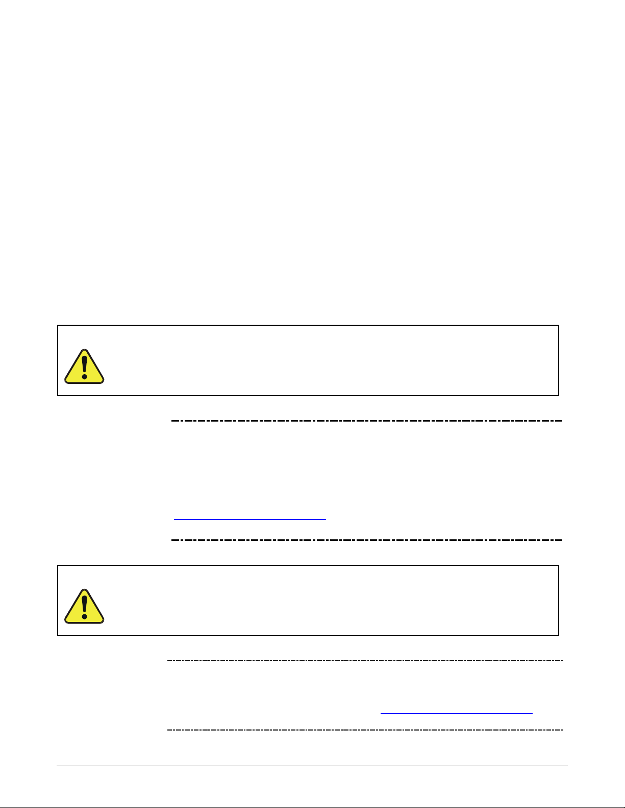
06807F DCN7335
3. GETTING STARTED
This section addresses the procedures for unpac king the instrument and i nspecting for
damage, presents clearance specifications for proper ventilation, introduces the
instrument layout, then presents the procedures for getting started: making electrical and
pneumatic connections, and conducting an initial calibration check.
UNPACKING THE T100 ANALYZER 3.1.
ATTENTION
CAUTION
GENER AL S AFETY HAZARD
Avoid personal injury: always use two persons to lift and carry the T100.
COULD DAMAGE INSTRUMENT AND VOID WARRANTY
Printed Circuit Assemblies (PCAs) are sensitive to electro-static
discharges (ESD) too small to be felt by the human nervous system.
Failure to use ESD protection when working with electronic assemblies
will void the instrument warranty. Refer to the manual on Fundamentals
of ESD, PN 04786, which can be downloaded from our website at
http://www.teledyne-api.com
the Special Manuals section.
Do not operate this instrument until you’ve removed dust plugs from
SAMPLE and EXHAUST ports on the rear panel!
under Help Center > Product Manuals in
CAUTION
Note Teledyne API recommends that you store shipping containers/materials
for future use if/when the instrument should be returned to the factory for
repair and/or calibration service. See Warranty section in this manual and
shipping procedures on our Website at
under Customer Support > Return Authorization.
27
http://www.teledyne-api.com
Getting Started Teledyne API - T100 UV Fluorescence SO
4 in.
1 in.
06807F DCN7335
Verify that there is no apparent external shipping damage. If damage has occurred,
please advise the shipper first, then Teledyne API.
Included with your analyzer is a printed record of the final performance characterization
performed on your instrument at the factory. It is titled Final Test and Vali dation Data
Sheet (P/N 04551). This record is an important quality assurance and calibration record
for this instrument. It should be placed in the quality records file for this instrument.
With no power to the unit, carefully remove the top cover of the analyzer and check for
internal shipping damage by carrying out the following steps:
1. Remove the two flat head, Phillips screws on the sides of the instrument;
2. Slide the cover backwards until it clears the analyzer’s front bezel, and;
3. Lift the cover straight up.
4. Ins pect the interior of the inst rument to ensure that all circ uit boards and other
components are in good shape and properly seated.
5. Chec k the connectors of the various internal wirin g harnesses and pneumatic
hoses to ensure that they are firmly and properly seated.
Analyzer
2
6. Verif y that all of the option al hardware or dered with t he unit has been install ed.
These are listed on the paperwork accompanying the analyzer.
WARNING
ELECTRICAL SHOCK HAZARD
Never disconnect PCAs, wiring harnesses or electronic subassemblies
while under power.
VENTILATION CLEARANCE 3.1.1.
Whether the analyzer is set up on a bench or install ed into an instrument rack, be sure to
leave sufficient ventilation clearance.
Table 3-1: Ventilation Clearance
AREA
Back of the instrument
Sides of the instrument
Above and below the
instrument
Various rack mount kits are available for this analyzer. Refer to Section 1.4 of this
manual for more information.
MINIMUM REQUIRED
CLEARANCE
1 in.
28
 Loading...