

804 Series Video Test Generator – User Guide
Page 1
Revision B3
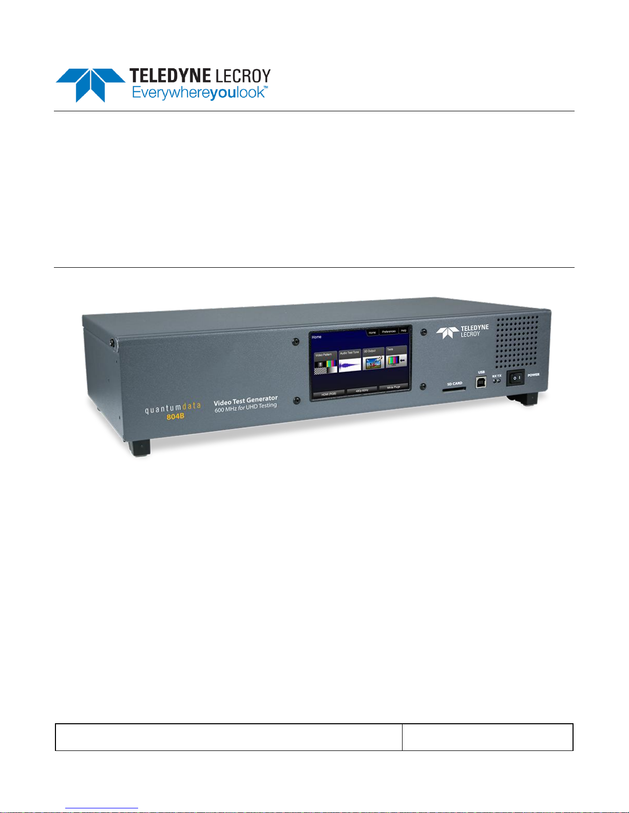
804/804A/804B Video Test Generators
User Guide
Rev: B3

804 Series Video Test Generator – User Guide
Page 2
Revision B3
Table of Contents
1 Overview ...................................................................................................................................4
1.1 804, 804A and 804B Models ................................................................................................... 4
1.2 Intended Use of the Product .................................................................................................... 4
1.3 Scope of this User Guide ......................................................................................................... 4
2 Customer Support for the 804/804A/804B ............................................................................5
3 Descriptions of Input and Outputs – Technical Specifications ...........................................6
3.1 Video Interfaces - Technical Specifications .......................................................................... 6
3.2 Audio Outputs - Technical Specifications .............................................................................. 7
3.3 Audio Inputs – Technical Specifications ................................................................................ 8
3.4 Control Interfaces and Devices – Technical Specifications................................................ 8
3.5 Size and Weight ........................................................................................................................ 9
3.6 Power Considerations ............................................................................................................. 10
3.7 Environmental Specifications ................................................................................................ 10
4 Installation Instructions ........................................................................................................12
4.1 The 804/804A/804B Shipping Box ....................................................................................... 12
4.2 Ventilation Requirements ....................................................................................................... 12
4.3 ESD Warning ........................................................................................................................... 12
4.4 Cleaning Considerations ........................................................................................................ 12
4.5 Desktop Installation Instructions ........................................................................................... 12
4.6 Rack mount Installation Instructions .................................................................................... 12
5 Instructions for Use................................................................................................................13
5.1 Powering up the 804/804A/804B .......................................................................................... 13
5.2 Powering down and uninstalling the 804/804A/804B ........................................................ 13
5.3 Front Panel Display ................................................................................................................. 15
5.4 Calibrating the LCD ................................................................................................................. 17
5.5 Front Panel LEDs .................................................................................................................... 18
5.6 Setting the 804/804A/804B Front Panel Mode ................................................................... 18
6 Using the 804 Series Command Line ...................................................................................20
6.1 Establishing an RS-232 connection to the 804/804A/804B .............................................. 20
6.2 Sending commands to activate the outputs ........................................................................ 21
7 Running Video Pattern Tests ................................................................................................23
7.1 Selecting a Signal Type .......................................................................................................... 23
7.2 Procedures for selecting a resolution and frame rate ....................................................... 27
7.3 Selecting Test Patterns .......................................................................................................... 31
7.4 Using Image Caching to render bitmaps quickly ................................................................ 33
7.5 Rendering 3D Test Patterns on an HDTV ........................................................................... 34
7.6 Using Custom Test Image Packs ......................................................................................... 35
8 Importing Custom Bitmaps...................................................................................................39
8.1 Workflow for Importing Bitmaps through USB .................................................................... 39
8.2 Procedures for Importing Bitmaps through USB ................................................................ 39
8.3 Workflow for loading bitmaps from the SD card ................................................................ 41
8.4 Procedures for Loading Bitmaps from SD Card ................................................................. 41
9 Creating and Using Custom Formats ...................................................................................43

804 Series Video Test Generator – User Guide
Page 3
Revision B3
10 Creating Custom Menus ........................................................................................................47
11 Running Audio Tests .............................................................................................................50
11.1 Testing HDMI Audio on an HDTV or A/V Receiver ............................................................ 50
12 Running Protocol Tests - Using the Front Panel GUI ........................................................57
12.1 Testing HDMI Protocols ......................................................................................................... 57
13 Using the Keypad ...................................................................................................................66
13.1 Connecting a Keypad ............................................................................................................. 66
13.2 Enabling and Configuring an RS-232 Keypad .................................................................... 66
13.3 Keypad Functionality ............................................................................................................... 66
13.4 Selecting a Format (Timing) .................................................................................................. 67
13.5 Selecting a Test Pattern (Image) .......................................................................................... 69
13.6 Programming a Test Sequence using the keypad ............................................................. 70
13.7 Programming a Test Sequence in the UserKeys file ........................................................ 72
14 Upgrading the 804/804A/804B ..............................................................................................74
14.1 Upgrading the Firmware and Gateware on your 804/804A/804B ................................... 74
15 Command Reference ..............................................................................................................77
15.1 Video-Related commands ...................................................................................................... 77
15.2 Administrative Commands ..................................................................................................... 92
15.3 HDMI Protocol Test Commands ........................................................................................... 94
15.4 Memory Commands ................................................................................................................ 94
15.5 Image Drawing Commands ................................................................................................... 95
15.6 Image Cache Commands ...................................................................................................... 95
15.7 Markers Commands ................................................................................................................ 95
15.8 Audio-Related commands ...................................................................................................... 96
16 List of Formats .......................................................................................................................99
17 List of Test Patterns .............................................................................................................110
804 Series Video Test Generator – User Guide
Page 4
Revision B3
1 Overview
This section provides an overview of the 804/804A/804B Video Test Generator and the scope of the User Guide.
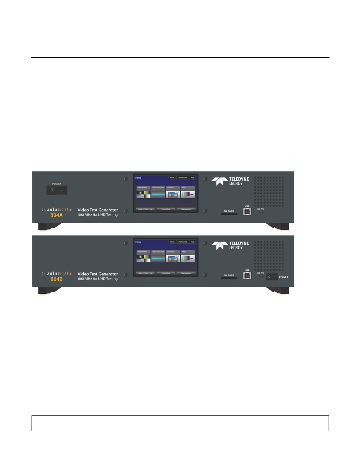
1.1 804, 804A and 804B Models
There are three models in the 804 series. The 804 Video Test Generator and the 804A Video Test Generator. The 804
supports HDMI pixel rates up to 165MHz. The 804A model supports pixel rates up to 300MHz (at 24 bit color). The 804A
therefore supports resolutions up to 4K x 2K at 50/60Hz with 4:2:0 pixel encoding as specified by the HDMI 2.0 specification.
The 804B model supports pixel rates up to 600MHz (at 24 bit color) at 50/60Hz with 4:4:4 pixel encoding. Each model
supports deep color.
1.2 Intended Use of the Product
The 804 series video generators are optimized for testing modern HDMI flat panel TVs. They feature 4 HDMI outputs—all
active simultaneously—for testing HDTVs with multiple HDMI inputs. This eliminates the cost of splitters often required for
testing each HDMI input on a TV. Each HDMI interface supports up to 36 bit/pixel (12-bit/component) deep color mode. The
804 series video generators can also output component analog and composite analog.
1.3 Scope of this User Guide
The 804 series Video Test Generator User Guide includes the necessary information to operate your 804 instrument. There is
a Quick Start Guide that covers some of the 804/804A/804B features as well.

804 Series Video Test Generator – User Guide
Page 5
Revision B3
2 Customer Support for the 804/804A/804B
The 804/804A/804B Video Test Generator is manufactured by Quantum Data:
Quantum Data, Inc.
2111 Big Timber Road
Elgin, IL USA
60123
Please check the Quantum Data website for updates to the user documentation and the firmware:
www.quantumdata.com/downloads
If you have a product support request you can contact Quantum Data customer support either by phone or by a web page.
The phone number is: 847-888-0450 x 456
For web support: http://www.quantumdata.com/support/index.asp
Note: This Guide is updated frequently. Please be sure to check the Quantum Data website for updates at:
www.quantumdata.com/downloads or www.quantumdata.com/products/804.asp.
804 Series Video Test Generator – User Guide
Page 6
Revision B3
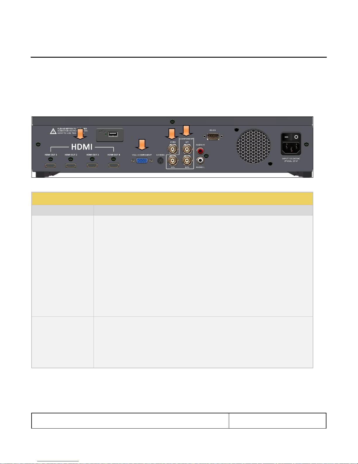
Table 3-1: 804/804A Video Interfaces
Video Connector
Description
HDMI (4) Output Type A
Menu Selection: HDMI
Bit Depth: 24/30/36 bit.
Video type: RGB, YCbCr.
Sampling: 4:4:4, 4:2:2 (and 4:2:0 for 4K formats on the 804A) .
Pixel rate (804): Timings up to 1080p60 (up to 165MHz).
Pixel rate (804A): HDMI timings up to 4K x 2K at 30Hz (up to 300MHz) as specified by the HDMI 1.4a
specification and 4K x 2K at 50/60Hz with 4:2:0 pixel encoding as specified by the HDMI 2.0 specification.
Pixel rate (804B): HDMI timings up to 4K x 2K at 50/60Hz (up to 600MHz) with 4:4:4 pixel encoding as
specified by the HDMI 2.0 specification.
Audio: LPCM, Dolby Digital and DTS (more details below).
Menu Selection: DVI for DVI Single Link (HDMI to DVI adapter cable).
Video type: RGB.
3 BNC
Menu Selection – Format Type: BNC + S-Video + CVBS (when ED/HD is selected)
Video type: YPbPr.
Bit Depth: 24 bit color depth.
Pixel rates: 27MHz, 27.027MHz, 74.176MHz, 74.25MHz (max 80MHz; resolutions greater than 80MHz
use pixel doubling).
Sync type: Composite.
3 Descriptions of Input and Outputs – Technical Specifications
This section describes the video and audio interfaces on the 804/804A/804B instrument:
3.1 Video Interfaces - Technical Specifications
Table 3-1 below describes the video interfaces on the 804/804A/804B instrument, these interfaces are used to render test
patterns for testing consumer electronic HDTVs and computer displays.
Note: All video interfaces on the 804/804A/804B shall be connected to only SEL V / double insulated circuits of other devices.
Note: SPDIF and Optical audio input connectors are not available on the newer 804 and 804A units.
804 Series Video Test Generator – User Guide
Page 7
Revision B3
VGA D-Sub
Menu Selection: VGA(HD15) Analog YPbPr for CE component analog.
Bit Depth: 24 bit color depth.
Video type: YPbPr (requires converter cable).
Pixel rates: 27MHz, 27.027MHz, 74.176MHz, 74.25MHz (max 80MHz; resolutions greater than 80MHz
use pixel doubling).
Pixel repetition to support higher pixel rates.
Sync types: Composite.
Menu Selection: VGA(HD15) Analog RGB for CE and IT component analog.
Bit Depth: 24 bit color depth.
Pixel rates (804/804A): 27MHz, 27.027MHz, 74.176MHz, 74.25MHz (max 80MHz; resolutions greater than
80MHz use pixel doubling).
Pixel rates (804B): 27MHz, 27.027MHz, 74.176MHz, 74.25MHz, 162MHz (max 162MHz).
Pixel repetition to support higher pixel rates.
Sync types: Separate.
(1) BNC CVBS & S-Video
Analog Composite Output
Menu Selection: BNC + S-Video + CVBS
Encodings: NTSC & PAL
Pixel Range: 13.5-13.52.
Sync type: Composite.
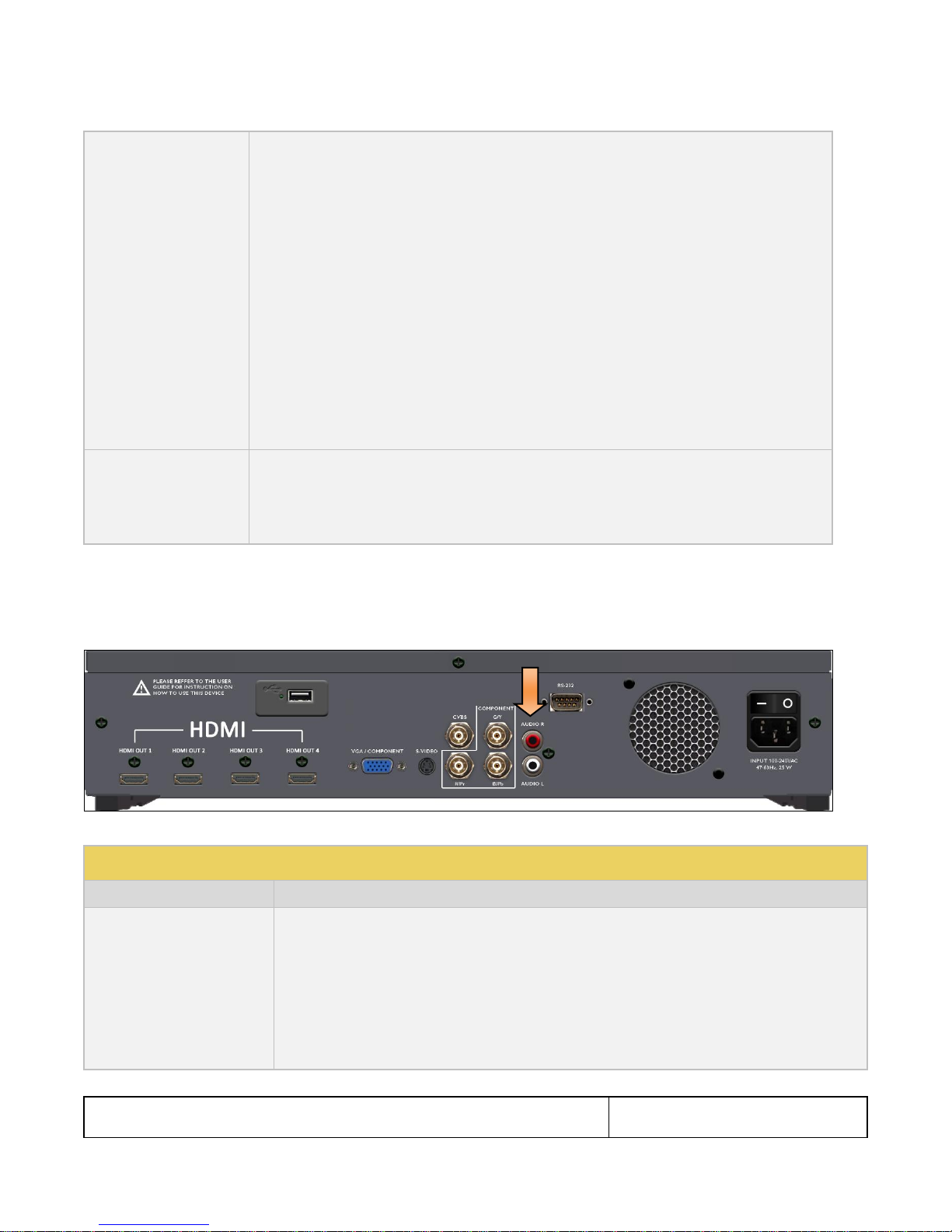
Table 3-2: 804/804A/804B Audio Outputs
Interface
Description
HDMI (4) Output Type A
Single link HDMI output connector. Supports the following HDMI features:
Channels: 8.
Bits per sample: 16, 20, 24.
Sampling rates (kHz): 32.0, 44.1, 48.0, 88.2, 96.0, 176.4, 192.0.
Formats: LPCM, Dolby Digital, Dolby Digital Plus, DTS-ES.
LPCM formats - Frequency adjustment: 10Hz to 20kHz in 1Hz increments.
LPCM formats - Amplitude adjustment: -99dB to 0dB in 1dB increments.
3.2 Audio Outputs - Technical Specifications
Table 3-2 below describes the audio outputs supported on the 804/804A/804B instrument.
Note: All audio interfaces on the 804/804A/804B shall be connected to only SEL V / double insulated circuits of other devices.
804 Series Video Test Generator – User Guide
Page 8
Revision B3
Analog Audio
(2) RCA audio connectors:
Channels: 2 (L/R).
Signal: Sine Wave.
Frequency: 10Hz to 20kHz in 1Hz increments.
Amplitude: -99dB to 0dB in 1dB increments.
Table 3-3: 804/804A/804B Digital Audio Inputs
Note: These connectors and the associated functions, are not available on new 804, 804A and 804B units
Interface
Description
SPDIF - RCA
SPDIF RCA audio connector
Optical – JIS FO5
Optical audio connector
3.3 Audio Inputs – Technical Specifications
Table 3-3 below describes the audio inputs supported on the 804/804A/804B instrument.
Note: All audio interfaces on the 804/804A/804B shall be connected to only SEL V / double insulated circuits of other devices.
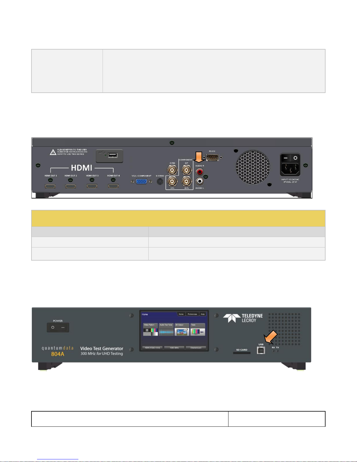
3.4 Control Interfaces and Devices – Technical Specifications
The following illustrations and Table 3-4 describe the control interfaces and devices on the 804/804A.
Note: All control interfaces on the 804/804A/804B shall be connected to only SEL V / double insulated circuits of other
devices.

804 Series Video Test Generator – User Guide
Page 9
Revision B3
Table 3-4: 804/804A/804B Control Interfaces and Devices
Interface
Function
RS-232
Command line control or control through Automated Test System (ATS). You can also connect a keypad to the RS-232 port for control
through a keypad. Keypad mode for the RS-232 interface is enabled or disabled through the Preferences menu.
USB Device
Updating firmware and gateware and command line control.
USB Host
Keyboard control.
SD Card
Updating firmware and gateware and loading bitmap test patterns.
Table 3-5: 804/804A/804B Dimensions and Weight
Parameter
Value
Height
3.25 inches; 8.3 cm
Width
16.5 inches; 41.9 cm
Depth
6.1 inches; 15.5 cm
Weight
6.62 lbs; 3.0 kg
3.5 Size and Weight
Table 3-5 provides the dimensions and weight of the 804/804A/804B:
804 Series Video Test Generator – User Guide
Page 10
Revision B3
Table 3-6: 804/804A804B Power Parameters
Parameter
Value/Range
Volts, Power
100 – 240 VAC, 24VA
Frequency
50Hz to 60Hz
Table 3-7: 804/804A/804B Environmental Parameters
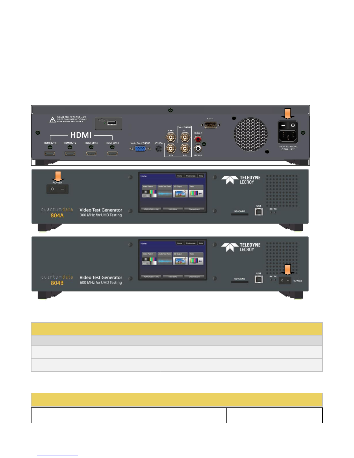
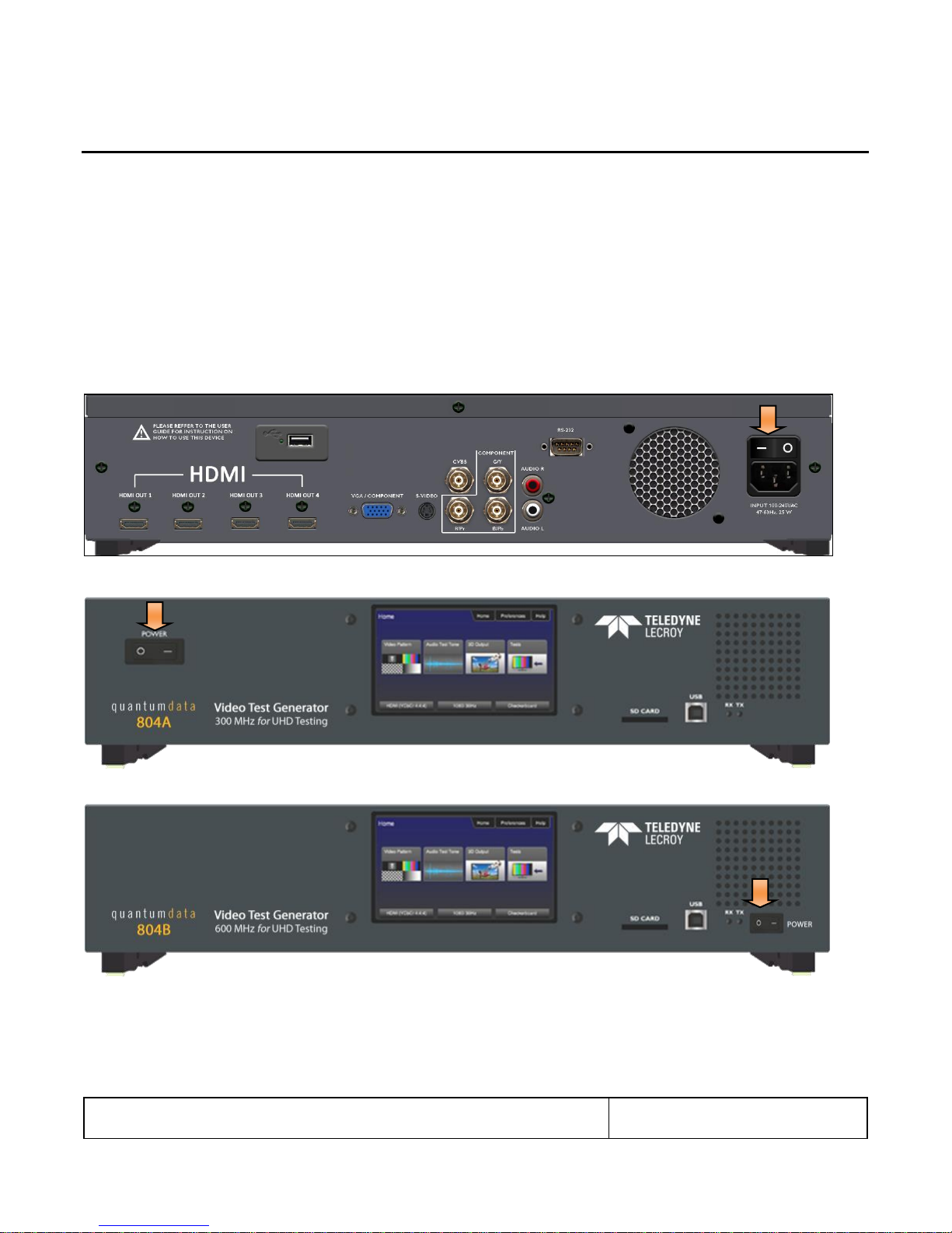
3.6 Power Considerations
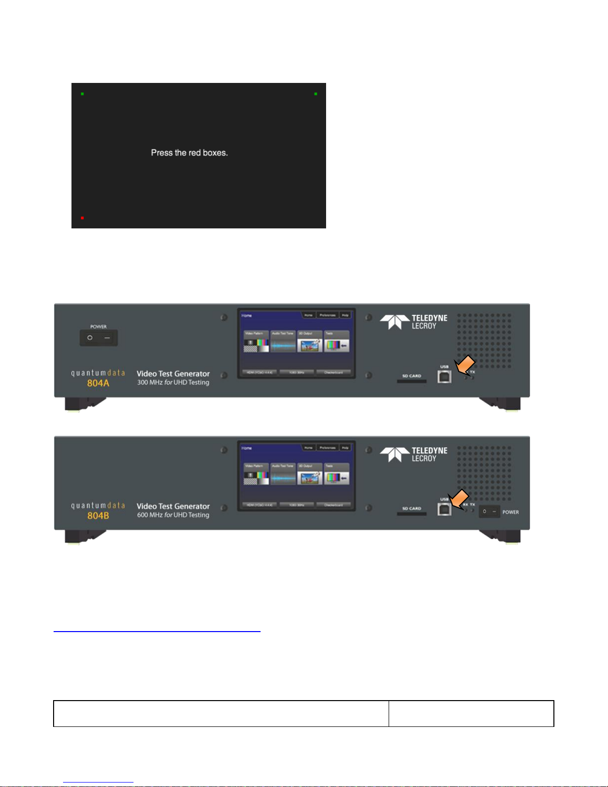
The 804/804A/804B has a rocker style power switch on the front panel and on the rear panel adjacent to the power line
connector. Both have to be on to operate the unit. Refer to the photos below.
Note: If the 804/804A/804B is used in a manner not specified in the guide, the protection provided by the equipment may be
impaired.
Table 3-6 provides the power requirements of the 804/804A/804B.
3.7 Environmental Specifications
Table 3-7 provides the environmental requirements and ratings of the 804/804A/804B.

804 Series Video Test Generator – User Guide
Page 11
Revision B3
Parameter
Value/Range
Operating Temperature Range
0 – 40 Deg C
Humidity
30% to 80%
Environmental IP rating
IP20

804 Series Video Test Generator – User Guide
Page 12
Revision B3
Table 4-1: What is in the 804/804A/804B Shipping Box
Item
Part Number
(optional) Cable kit
95-00068
Mounting kit; either or both:
- 804 Desktop kit
(feet already installed)
- 804 Rack Mount Kit (not installed)
95-00066
95-00067
Power cord; one of:
- USA Power Lead
- European Power Lead
- UK Power Lead
30A00400A03
30-00174
30-00175
Quick Start Guide
68-00222
4 Installation Instructions
This section describes how to install the 804/804A/804B. The 804/804A/804B can be installed either as a desktop instrument
or it can be rack mounted in a standard 19 inch relay rack.
4.1 The 804/804A/804B Shipping Box
Table 4-1 below describes the video interfaces on the 804/804A/804B instrument, these interfaces are used to render test
patterns for testing consumer electronic HDTVs and computer displays.
4.2 Ventilation Requirements
The 804/804A/804B has an internal fan and two vents, one in the front and the other in the rear. Please be sure that the vents
are not blocked with debris or by other equipment. Be sure to leave at least 4 inches of room between the 804/804A/804B
vents and any other equipment or object.
4.3 ESD Warning
Uncontrolled electrostatic discharge can damage sensitive electronic equipment. Please follow proper electrostatic control
procedures including using ground straps when working with the model 804/804A/804B. While the 804/804A/804B contains
circuitry to protect it from reasonable electrostatic discharge, it can still be damaged by excessive discharge. Moderate
discharge may degrade operation such as the user display. If that is observed, restarting the unit should eliminate the
problem.
4.4 Cleaning Considerations
Please be sure that the vents are not blocked with debris or dust. Periodically check to ensure that there is no dust or debris
blocking the ventilation openings of the 804/804A/804B.
4.5 Desktop Installation Instructions
If you have ordered the desktop option, the feet will be installed on the bottom of the 804/804A. There will be no mounting
ears included. There are no special installation instructions for a desktop application.
4.6 Rack mount Installation Instructions
If you have ordered the rack mount option, the unit will be shipped with the mounting ears attached but there will be no feet on
the bottom of the 804/804A/804B. You will need to screw the unit into the 19 inch rack using screws appropriate for the rack.
Quantum Data does not provide screws for this purpose.
804 Series Video Test Generator – User Guide
Page 13
Revision B3
5 Instructions for Use
This section provides the Instructions for Use for the 804/804A/804B describes power up and general operation.
Note: If the 804/804A/804B is used in a manner not specified in the guide, the protection provided by the equipment may be
impaired.
5.1 Powering up the 804/804A/804B
The procedures below describe how to power up the 804/804A/804B.
1. Connect the power cable provided with the 804/804A/804B to the connector on the back. Refer to the illustration below.
Note: Any replacement power cord that you use should be certified to the requirements in IEC 60799.
2. Apply power on the power connector switch on the back near the power connector.
3. Power up the 804/804A/804B using the rocker switch on the front panel.
5.2 Powering down and uninstalling the 804/804A/804B
In the event you have to remove the 804/804A/804B from its normal operating location, use the following instructions:
1. Power down the 804/804A/804B using the rocker power switch on the front of the unit.

804 Series Video Test Generator – User Guide
Page 14
Revision B3
2. Turn the power of using the rocker power switch on the back near the power connector.
3. Disconnect the power cable from the rear of the unit. Note that the power cord is easily accessible when fully plugged in
such that an operator can manually remove the power cord.
804 Series Video Test Generator – User Guide
Page 15
Revision B3
Table 5-1: Top Level Menu
Item
Submenu - Pattern
Third Level Menu
Value
Top Menu Bar
Home
See Below
N/A
Preferences
Audible Touch
Off
On
Screen Brightness
Min
25%
50%
75%
Max
USB Mode
COM for commands
Disk for downloading files and upgrades
Startup Mode
Default – Use default menus on touch screen on startup.
Custom Menu – Use custom menus on touch screen on
startup.
AVmute on Format
Change
Enables or disables AVMute on the HDMI output when
there is a format change.
RS-232 Keypad Mode
Off – Keypad operation on the RS-232 interface is disabled.
On – Keypad on the RS-232 interface is enabled.
RS-232 Baud Rate
One of: 1200, 2400, 4800, 9600,14400,19200, 28800,
38400, 57600, 115200, 230400
Help
Upgrades
Erase
Update (Application Flash)
Update (FPGA Flash)
Function Buttons
Video Patterns
See below: Selecting Test Patterns
Audio Tones
See below: Testing HDMI Audio on an HDTV or A/V Receiver
3D Output
5.3 Front Panel Display
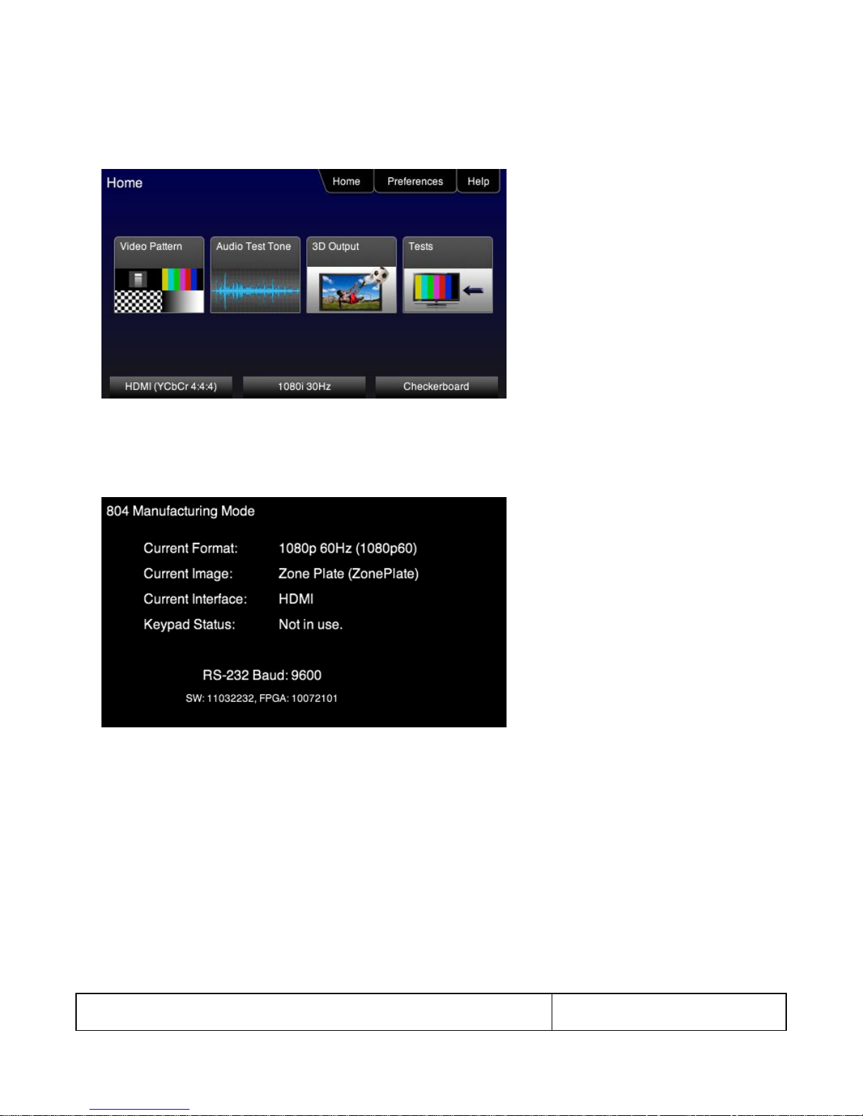
The 804/804A/804B has a 480(H) by 272(V), 24 bit color status display shown below. There are two modes of operation: 1)
Manufacturing mode enabled (Status only displayed) and 2) Manufacturing mode disabled (active touch panel display). When
Manufacturing mode is enabled, the display shows the following information:
Active format
Active test pattern
Active interface(s)
Keypad Status
RS-232 Baud Rate
S/W version
FPGA version
Table 5-1 below shows functions available in the top level menu.
804 Series Video Test Generator – User Guide
Page 16
Revision B3
Tests
See below: Testing HDMI Protocols
Bottom Status Buttons
Signal Type
See below: Selecting a Signal Type
Resolution
See below: Procedures for selecting a resolution and frame rate
Video Pattern
See below: Selecting Test Patterns
804 Series Video Test Generator – User Guide
Page 17
Revision B3
5.4 Calibrating the LCD
You can calibrate the touch screen of your 780 if necessary.
Important Note: Please follow the procedures below carefully. Improper calibration can lock the unit up. It is preferable that
you contact Quantum Data Support unless you have learned how calibrated the screen properly.
Use the following procedures to perform the calibration.
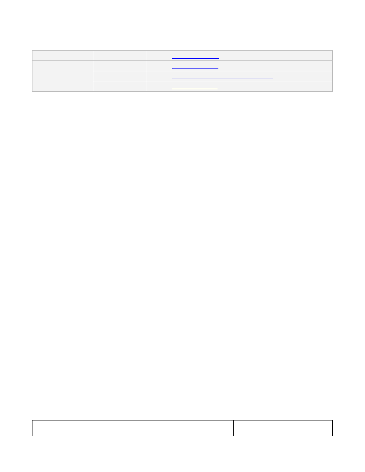
1. From the Home menu, navigate to the Help menu by pressing the Help activation button on the upper status bar. The
Home menu is shown below.
The Help menu appears as shown below:
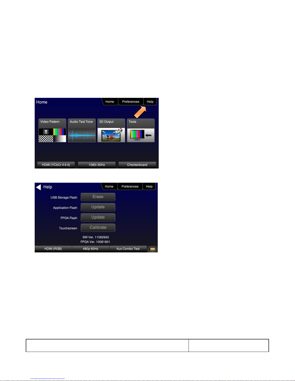
2. Touch select the Calibrate activation button to launch the calibration screen.
Alternatively you can initiate the calibration screen using the following command:
TCAL
The calibration screen instructs you to touch each of four red squares.
804 Series Video Test Generator – User Guide
Page 18
Revision B3
When you finish touch selecting the fourth box, the calibration is completed and you will return to the Home menu.
5.5 Front Panel LEDs
The 804/804A/804B has two LEDs on the front to indicate the status of the Tx and Rx activity of the RS-232 interface. Note
that when you send a command you will see the Tx and Rx lights on the 804/804A/804B front panel flash briefly.
5.6 Setting the 804/804A/804B Front Panel Mode
The 804/804A/804B front panel can be operated in one of two modes: 1) Touch screen mode and 2) 804/804A/804B
Manufacturing (Status only) mode. The Touch Screen mode enables you to fully operate the 804/804A/804B through the
color touch display. The procedures for operating the 804/804A/804B through the front panel are provided in the section
Running Protocol Tests - Using the Front Panel GUI.
Typically you would use the Manufacturing (status only) mode when you were operating the 804/804A/804B through the
command line via either a keypad or an automated test system.
Use the following procedure to set the 804/804A/804B front panel display mode.
1. Set the 804/804A/804B display mode to the Touch Screen mode using the following command.
804 Series Video Test Generator – User Guide
Page 19
Revision B3
MFGM 0
The front panel display will show the Home screen as shown in the following screen shot.
2. Set the 804/804A/804B display mode to the Manufacturing mode using the following command.
MFGM 1
The front panel display will appear as shown in the following screen (example only).

804 Series Video Test Generator – User Guide
Page 20
Revision B3
6 Using the 804 Series Command Line
This section provides procedures on controlling the 804/804A/804B through the command line for testing HDTVs. Refer to the
section entitled, Command Reference for a complete list of commands. You can connect from a PC either through an RS-232
cable or a USB cable.
6.1 Establishing an RS-232 connection to the 804/804A/804B
The procedures below describe how to connect to the 804/804A/804B through the RS-232 interface for command line control
or control from an automated test system.
1. Connect an RS-232 cable between your host PC and the 804/804A/804B. The illustration below shows the location of the
RS-232 interface.
2. (optionally) Connect USB cable between your host PC and the 804/804A/804B on the USB connector on the front. The
illustration below shows the location of the USB interface.
3. Download the .INF file from the Quantum Data website at:
http://www.quantumdata.com/support/804readme.asp#supplemental or
http://www.quantumdata.com/support/804Areadme.asp#supplemental to your PC and unzip the file. Store it in
a convenient location on your PC.
4. Set the USB mode to COM from the Preference menu as shown below. Reboot the 804/804A/804B if you changed this
USB mode from Disk to COM.

804 Series Video Test Generator – User Guide
Page 21
Revision B3
5. Establish a connection using a terminal program such as Hyperterm or an Automated Test System (ATS). You will need
to know the port number for the USB connector. This can be found in the Device Manager in a Windows OS.
6. Press the More button to access the RS-232 Baud Rate setting as follows:
Bits per second: 115200 or 9600
Data bits: 8
Parity: None
Stop bits: 1
Flow control: None
Note: You do not need to set the baud rate if you are using the USB connection.
When you send a command you will see the Tx and Rx lights on the 804/804A/804B front panel flash briefly.
6.2 Sending commands to activate the outputs
The following examples depict some commonly used commands for controlling the 804/804A/804B outputs.
1. Activate the HDMI interfaces:
XVSI 4
ALLU
2. Load and activate a format.
FMTL 720p60

804 Series Video Test Generator – User Guide
Page 22
Revision B3
FMTU (or ALLU)
FMTU?
720p60
Note: Please refer to the section: List of Formats for a list of format timings supported.
3. Select and activate a test image:
IMGL SMPTEbar
IMGU
Note: Please refer to the section: List of Test Patterns for a list of test patterns supported.
4. Change the sampling to 4:2:2:
DVSM 2
ALLU
5. Set the digital audio to HDMI:
DASI 6
ALLU
6. Enable the analog audio:
AASI 1
ALLU
7. Set all channels to 1kHz on LPCM formats on the HDMI digital audio output:
SRAT 1000
ALLU
8. Set audio sampling rate to 48kHz on LPCM formats on the HDMI digital audio output:
ARAT 48000
ALLU
9. To view the summary page of the EDID report for the display connected to the third HDMI port:
DIDT? 2

804 Series Video Test Generator – User Guide
Page 23
Revision B3
Table 7-1: Signal Type
Signal Type Menu Selection
Physical Connector(s)
Option
Output Selections
HDMI
HDMI via HDMI to HDMI cable (available
with optional cable kit)
Color Space
RGB
YCbCr 4:4:4
YCbCr 4:2:2
YCbCr 4:2:0 (804A for 4K formats @ 60Hz)
Bit Depth
8
10
12
Format Type
TV – CE formats
Computer – VESA formats
DVI
HDMI via HDMI to DVI cable (available with
optional cable kit)
Format Type
TV – CE formats
Computer – VESA formats
VGA(HD15) Analog YPbPr
HD-15 (VGA) via VGA cable to 3 RCA
converter cable (available in the optional
cable kit)
Sync Type
Sep[arate] Sync
Sync on Y
VGA(HD15) Analog RGB
HD-15 (VGA) via VGA cable (available in
the optional cable kit)
Format Type
TV – CE formats
Computer – VESA formats
Sync Type
Sep[arate] Sync
Sync on Green
BNC + S-Video + CVBS
CVBS (BNC) and S-Video
(3) BNC (ED/HD)
Format Type
SD – TV composite video (NTSC & PAL
formats)
ED/HD – TV formats for component video
7 Running Video Pattern Tests
This section provides the Instructions for running video tests on the 804/804A/804B. Procedures are provided for operation
both through the front panel and the command line.
Note: If the 804/804A/804B is used in a manner not specified in the guide, the protection provided by the equipment may be
impaired.
7.1 Selecting a Signal Type
Use the information in Table 7-1 below as a guide:
1. Power up the 804/804A/804B using the rocker switch on the back panel and the front panel. The On position is with the
toggle switch depressed on the inner side of the switch.
Refer to the procedures in the section Instructions for Use.
2. Make the cable connection between the appropriate output connector(s) on the 804/804A/804B and the input connectors
of the HDTV using the cables supplied. Refer to the figure below to view the locations of the video outputs.
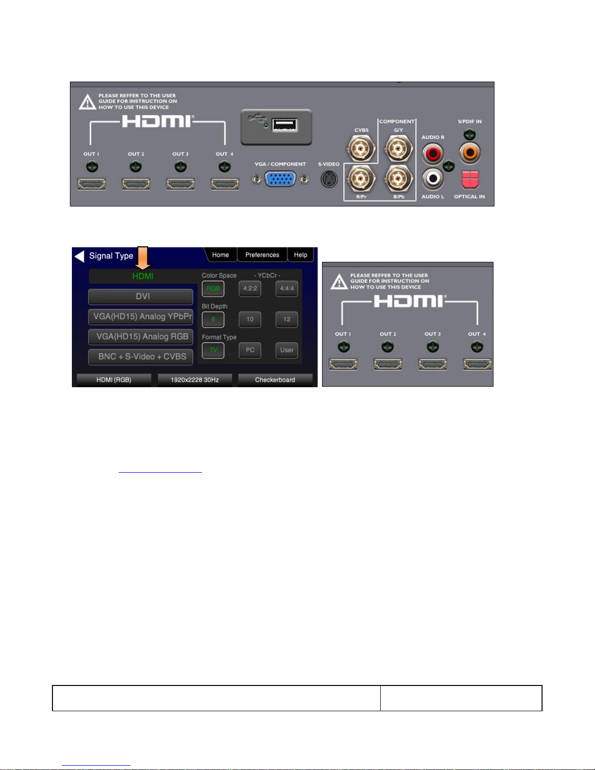
804 Series Video Test Generator – User Guide
Page 24
Revision B3
3. Touch select the Signal Type activation button on the panel on the left. The following screen appears:
4. (For HDMI) Touch select the HDMI option using the associated activation button as shown below.
Alternatively, to activate HDMI output through the command line:
XVSI 4 // selects the HDMI output
ALLU // activates the output
Note: There are several optional settings and features related to HDMI that you may wish to utilize. They pertain to
enabling and disabling various HDMI metadata and AVmute. These options are executed through the command line.
Refer to the Command Reference chapter for information on these commands. The following is an example of how you
would enable or disable AVmute.
AVMG 1 // sets (enables) AVmute on the HDMI output
AVMG 0 // clears (disables) AVmute on the HDMI output
(For DVI TVs) Touch select the DVI option and then the TV option using the associated activation buttons as shown
below.

804 Series Video Test Generator – User Guide
Page 25
Revision B3
Alternatively, to activate DVI for computer formats through the command line:
XVSI 3 // selects the DVI TV output through the HDMI connector
ALLU // activates the output
(For DVI computers) Touch select the DVI option and then the Computer option using the associated activation buttons
as shown below.
Alternatively, to activate DVI output through the command line:
XVSI 2 // selects the DVI computer through the HDMI connector
ALLU // activates the output
5. (For component analog displays) Touch select the VGA (HD15) Analog YPbPr option and then the desired sync option
using the associated activation buttons as shown below.
804 Series Video Test Generator – User Guide
Page 26
Revision B3
Alternatively, to activate the VGA (HD15) Analog YPbPr output through the command line:
XVSI 9 // selects YPbPr Analog output through the VGA connector
SSST 1 // selects separate sync. Use SSST 3 for sync on Y
ALLU // activates the output
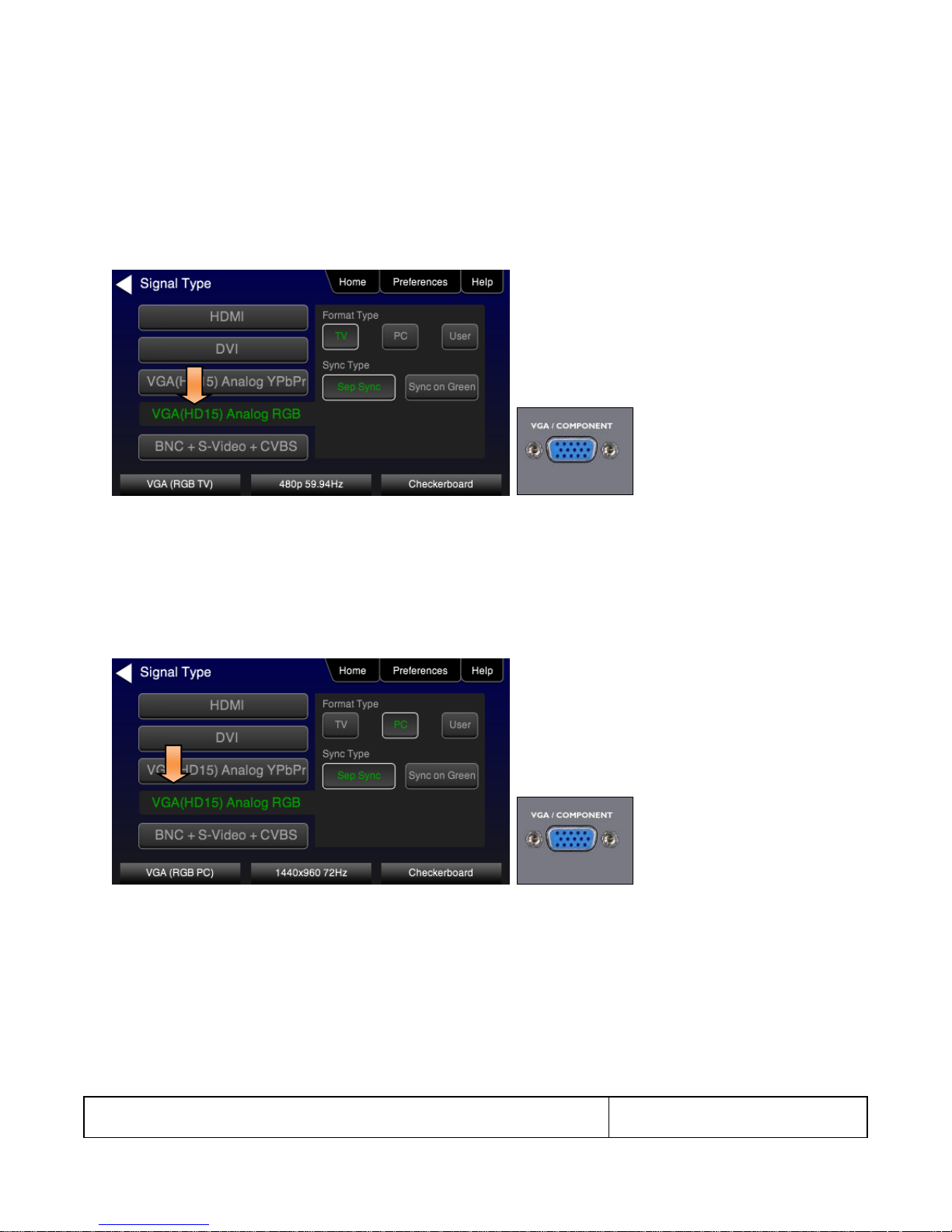
6. (For component analog TV displays) Touch select the VGA(HD15) Analog RGB option with the TV Format Type and
then the desired sync option using the associated activation buttons as shown below.
Alternatively, to activate RGB Analog output through the command line:
XVSI 9 // selects RGB component analog for TVs through VGA output
SSST 1 // selects separate sync. Use SSST 3 for sync on Y
ALLU // activates the output
7. (For component analog computer displays) Touch select the VGA(HD15) Analog RGB option with the Computer Format
Type and then the desired sync option using the associated activation buttons as shown below.
Alternatively, to activate RGB component analog for computers through the command line:
XVSI 9 // selects component analog for computers through VGA output
ALLU // activates the output
8. (For composite TV) Touch select the BNC + S-Video + CVBS option with the SD Format Type using the associated
activation buttons as shown below.
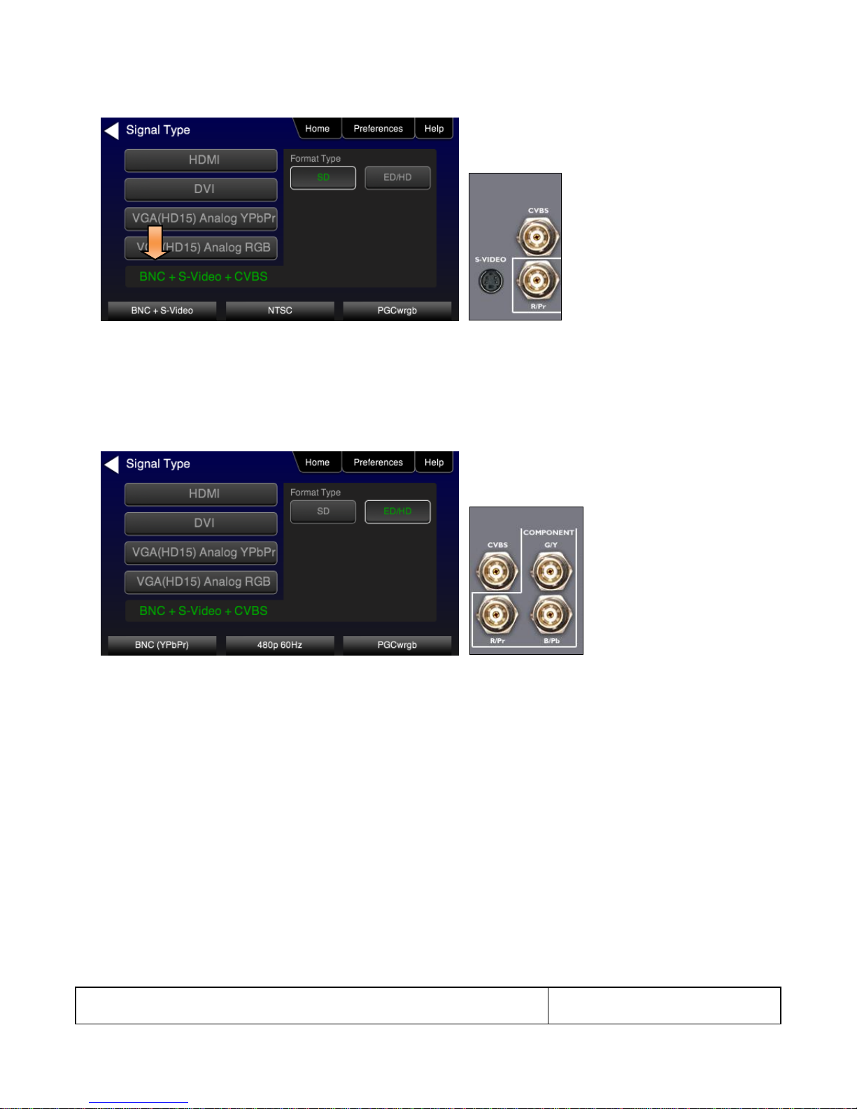
804 Series Video Test Generator – User Guide
Page 27
Revision B3
Alternatively, to activate composite video output through the command line:
XVSI 6 // selects analog composite video through CVBS and S-Video outputs
ALLU // activates the output
9. (For component TV) Touch select the BNC + S-Video + CVBS with the ED/HD Format Type using the associated
activation buttons to activate component video through the BNC connectors as shown below.
XVSI 6 // selects analog component through BNC outputs
ALLU // activates the output
7.2 Procedures for selecting a resolution and frame rate
The procedures below describe how to select the resolution.
1. From the Home menu select Tests.
The front panel display will show the Home screen as shown in the following screen shot.
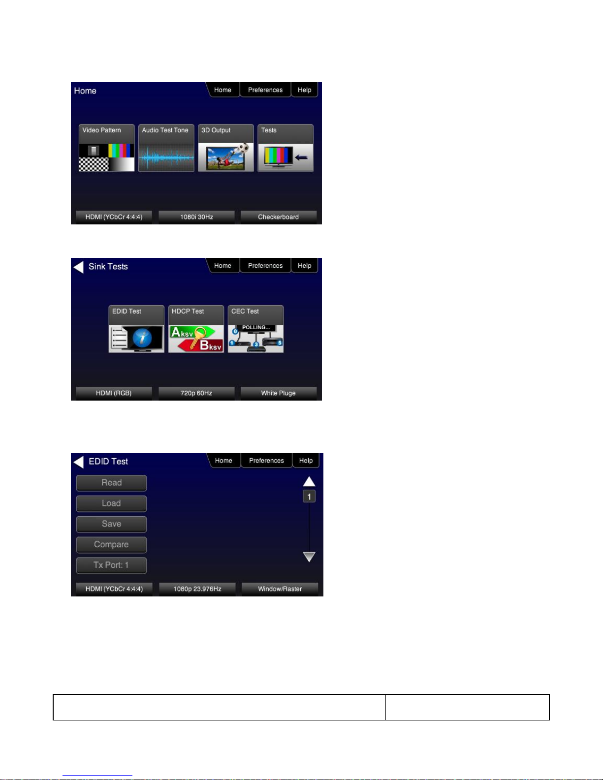
804 Series Video Test Generator – User Guide
Page 28
Revision B3
The Sink Tests menu appears as shown below.
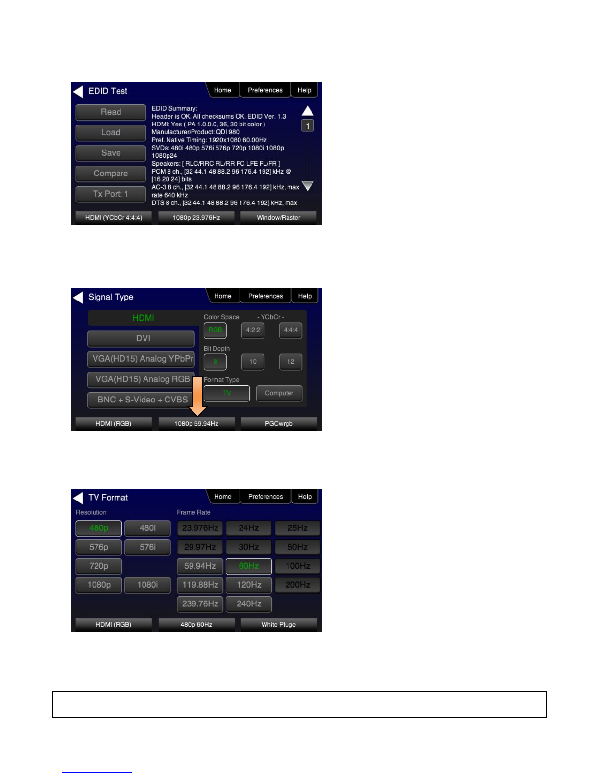
2. Touch select EDID Test from the Sink Tests menu.
The EDID Test menu appears as shown below.
3. Touch select the lower button (Tx Port x) on the EDID Test menu shown below.
Note: You will have to select each HDMI port in sequence.
4. Touch select Read from the EDID Test menu shown below.
The EDID test results are shown. A summary page appears first.
804 Series Video Test Generator – User Guide
Page 29
Revision B3
5. (For HDMI) Repeat for each HDMI port you wish to test.
6. Touch select the resolution and frame rate (middle button on the bottom panel). Refer to the figures below which show
HDMI examples.
The HDMI TV Format screen appears as shown below. The first screen is from the 804. The second and third screens
are from the 804A with its support for 4K x 2K resolutions at 30Hz or 50/60Hz with HDMI 2.0 4:2:0 pixel encoding. The
third screen shows an example from the 804B with its support for 4K x 2K resolutions with 4:4:4 pixel encoding.
Sample screen for the 804A:

804 Series Video Test Generator – User Guide
Page 30
Revision B3
The following screen shows an 804A screen with 4K selected at 50/60Hz using 4:2:0 pixel encoding.
The following screen shows an 804B screen with 4K selected at 50/60Hz using 4:4:4 pixel encoding.

804 Series Video Test Generator – User Guide
Page 31
Revision B3
For the HDMI, DVI and VGA computer formats, there are color codes that are applied to the Resolution and Frame Rate
selections. The following is a summary of their meaning:
A Resolution or Frame Rate with white lettering but with no outline – The Resolution or Frame Rate has a short video
descriptor associated with it.
A Resolution with green lettering – The Resolution that is currently selected.
Frame Rate(s) with green lettering and with white outline – The Frame Rate along with the currently selected
Resolution.
A Frame Rate with black lettering but with no outline – The Frame Rate is not supported by the standard for the
selected resolution.
7. Touch select the resolution and frame rate.
Alternatively, to select the resolution and frame rate through the command line:
FMTL 720p60 // loads format (resolution and frame rate)
FMTU // activates format
Note: There are 4 HDMI connectors on the 804/804A. You can set a marker to indicate which output is currently active.
To set the marker use the following command:
HPMG 1 // enables markers (0 disables markers)
To change the size of the markers:
HPMX 100 // changes the size of the marker’s width to 100 pixels
HPMY 50 // changes the size of the marker’s height to 50 lines
7.3 Selecting Test Patterns
This subsection describes how to select test patterns once the desired signal type and format (resolution / frame rate) has
been selected.
The procedures below cover cases where there is a direct connection between the 804/804A/804B and the display and also
where the 804/804A/804B is connected to a display through a repeater device.
1. From the main menu screen (shown below), touch select Video Pattern.

804 Series Video Test Generator – User Guide
Page 32
Revision B3
The following menu appears.
2. Touch select the desired test pattern from the menu shown below. You can select patterns that are standard with the
804/804A/804B or bitmaps that you have imported.
Note: A “+” on the lower right portion of the pattern indicates that there are options related to the specific pattern. In these
cases you double touch select to access the lower level menu.
Alternatively, to load a test patterns through the command line:
IMGL smptebar // loads image
IMGU // activates image

804 Series Video Test Generator – User Guide
Page 33
Revision B3
3. (If applicable) Specify the test pattern options. Refer to the section List of Test Patterns for a description of each option.
7.4 Using Image Caching to render bitmaps quickly
The Image Cache feature enables you to render bitmap images quickly. This feature is ideal for production lines in
manufacturing.
The Image Cache feature is configured using the command line interface. Once configured the 804/804A/804B renders
bitmap images in advance and stores them in memory for immediate recall. The number of images that can be stored in
cache depends on the resolution and bit depth of the chosen format. The cached images are stored in video RAM, and are
lost on power cycle, reboot, or issuance of the ICHC command.
Use the procedure below to render bitmap images quickly with the Image Cache feature.
1. Load the desired bitmaps into the 804/804A/804B using the procedures in the section Workflow for Importing Bitmaps.
2. Create the userpats.txt file which maps the bitmap images to aliases. Use the example below:
The structure of the UserPats file is:
<bmpname.bmp> space <description>
The contents of the UserPats.txt text file would be:
720Img1.bmp Master 1280x720 - (this maps to alias “User00”)
720Img2.bmp Master 1280x720 - (this maps to alias “User01”)
720Img3.bmp Master 1280x720 - (this maps to alias “User02”)
1080Img1.bmp Master 1920x1080 - (this maps to alias “User03”)
1080Img2.bmp Master 1920x1080 - (this maps to alias “User04”)
1080Img3.bmp Master 1920x1080 - (this maps to alias “User05”)
Note 1: The bitmap name has to match the name of the stored bitmap.
Note 2: The bitmap name uses the 8.3 character structure.
Note 3: The description is limited to 20 characters.
3. Establish a command line session to the 804/804A/804B using the procedures in the section Establishing an RS-232
connection to the /804B.
4. Create and load the bitmap images in cache. The example below illustrates how to load formats and cached images.
ICHC // clears the cache
FMTL 720p60 // loads the 720p60 format
FMTU // applies the format
IMGL User00 // loads the first bitmap image stored in the userpats.txt file
IMGU // applies the image
ICHS // save the bitmap into cache
IMGL User02 // loads the third bitmap image stored in the userpats.txt file
IMGU // applies the image
ICHS // save the bitmap into cache
FMTL 1080p60 // loads the 1080p60 format
FMTU // applies the format
IMGL User03 // loads the fourth bitmap image stored in the userpats.txt file
IMGU // applies the image
ICHS // save the bitmap into cache
IMGL User05 // loads the sixth bitmap image stored in the userpats.txt file

804 Series Video Test Generator – User Guide
Page 34
Revision B3
IMGU // applies the image
ICHS // save the bitmap into cache
Note: Whenever you load these bitmap images either from the front panel or the command line they will be loaded from
cache and will be rendered on the display more quickly. But it is important to understand that each bitmap image is
specific to a particular format resolution. Therefore, you will have to select the bitmap such that it is consistent with the
resolution of the format that is active.
7.5 Rendering 3D Test Patterns on an HDTV
This subsection describes how to render 3D test patterns and bitmaps on an HDTV. The 804/804A/804B supports Side-bySide, Top-and-Bottom and Frame Packing (for both interlaced and progressive timings) 3D format structures. You can render
bitmaps that you have or create or you can render 3D test patterns in the 804/804A/804B test pattern library.
You can obtain 3D bitmaps in three ways:
Develop your own 3D bitmaps.
Sample 3D bitmaps from the Quantum Data website (www.quantumdata.com/downloads).
Generate 3D bitmaps from your own stereoscopic image pairs using the Quantum Data 3D Bitmap Conversion Tool
available from the Quantum Data website (www.quantumdata.com/downloads).
Once you have the 3D bitmaps you can transfer them to the 804/804A/804B using the procedures described in the
section Importing Custom Bitmaps.
Use the following procedures to render 3D Bitmaps or 3D Test Patterns on HDMI Sink Device.
1. Select a format that is suitable for rendering 3D images such as 720p60 and 1080. Use the procedures above in the
section Procedures for Selecting an HDMI Resolution and Frame Rate.
If you have used the Quantum Data 3D Bitmap Conversion Tool, there is a naming convention for the 3D bitmaps which
also provides the required format for each specific bitmap.
2. Touch select 3D Output option from the top level menu shown below.
The following screen will appear:

804 Series Video Test Generator – User Guide
Page 35
Revision B3
3. Select the 3D mode (Side-by-Side, Top-and-Bottom or Frame Packing) and then select the subtype and Left/Right
options (if applicable).
4. Select the 3D bitmap image or test pattern from the Test Pattern list (see screen example below). Refer to the section:
List of Test Patterns for a complete list of 3D test patterns.
Note: When rendering bitmaps, you will have to make sure that the 3D bitmap you use matches your selection of 3D
formats and timing (resolution). In the example above, a 3D Frame Packing bitmap is selected for 1280 x 720. Therefore
you have to make sure that you select that specific timing (i.e. 1280 x 720) and that specific 3D format structure (Frame
Packing).
7.6 Using Custom Test Image Packs
The 804/804A/804B provides licensed image packs for certain sets of test images. You need to have a license key to use
these custom test image packs. You can arrange to get access to them by contacting Quantum Data customer support at:
http://www.quantumdata.com/support.
When you purchase an image pack it appears as an icon at the end of the list of Test Patterns. A sample screen is shown
below (Philips1, ChinaRes, Master). You simply select one of the test patterns (e.g. ChinaRes in the screen example below).
They will take a few seconds to load. They will load at the resolution of the format that you have selected.

804 Series Video Test Generator – User Guide
Page 36
Revision B3
Table 7-2: Custom Test Image Packs
ChinaRes Pattern Pack
This is a bitmap that is available through the Image Packs
option. The ChinaRes test pattern is specified by the National
Testing and Inspection Center for Radio and TV Products of
China.
The image pack includes both a standard definition aspect
ratio (shown right) and a high definition aspect ratio. This test
pattern is supported at: 1920x1080, 1280x720, 720x576 and
720x480 resolutions.
The following is a description of the elements in this test
image
1. Overscan gauges to determine percentage of overscan.
2. Centered cross, centered circles, and centered grid to
test centering and concentricity.
3. White grid to test convergence.
4. Central resolution wedge gauges for vertical, horizontal,
and diagonal resolutions.
5. Corner resolution wedge gauges for vertical and
horizontal resolutions.
6. 4-quadrant horizontal and vertical test areas to judge
resolution and display artifacts.
7. Color bar for testing color purity and chroma delay.
8. 10-step grayscale to test brightness, contrast, and
luminance.
9. Split (left and right) grayscales for testing dark-field and
bright-field gray levels.
Average picture level is approximately 50%.
1
2
3
4
5
6 7 8
9
Refer to the table 7-2 below for a description and depiction of the Image Packs currently offered.

804 Series Video Test Generator – User Guide
Page 37
Revision B3
Table 7-3: Custom Test Image Packs – THX Test Patterns
THX Test Patterns
The THX Pattern Pack offers a variety of test patterns
for calibrating the luminance and chrominance of high
end 3D-capable HDTVs. The following is a list of test
patterns provided in this optional test pattern package.
3D Convergence - test patterns to align pixels for proper convergence.
3D Crosstalk – test patterns to determine level of 3D crosstalk.
Color Gamut – 2D/3D primary and secondary color patterns to fine-tune colors and
gamma.
Picture performance – pattern within THX Optimizer to verify accuracy of skin tones.
THX Optimizer - test patterns to easily adjust brightness, contrast, color, tint, etc.

804 Series Video Test Generator – User Guide
Page 38
Revision B3
Table 7-3: Custom Test Image Packs – THX Test Patterns
THX box - 2D/3D grayscale test patterns to accurately adjust white point and gamma.

804 Series Video Test Generator – User Guide
Page 39
Revision B3
8 Importing Custom Bitmaps
You can import your own bitmaps into the 804/804A/804B through the USB interface or from an SD card. The 804A and 804B
support 4K x 2K bitmaps. Note that when bitmaps are imported into the 804/804A/804B, they are rendered at their native
resolution, i.e. they do not scale to the resolution of the video format you have selected as the standard test patterns do.
Therefore, if you want to test with a specific bitmap pattern for each resolution and you want the bitmap to fill the entire
display, you would need to import a separate bitmap of that image for each resolution you wish to test.
8.1 Workflow for Importing Bitmaps through USB
In order to import and use bitmaps in the 804/804A/804B you must take the following high level steps (detailed procedures
are provided further below):
Place the 804/804A/804B’s USB interface in the Disk mode.
Create a text file called “UserPats.txt” that lists each bitmap stored for use. The name in the file has to match the
name of the bitmap. The procedures below provide an example of this text file.
Transfer the UserPats.txt file to the 804/804A/804B over the USB interface.
Transfer the bitmap(s) over to the 804/804A/804B flash memory through the USB interface.
8.2 Procedures for Importing Bitmaps through USB
Use the procedures below to import bitmaps.
1. Connect the 804/804A/804B to a PC host via the USB cable provided.
2. Select the Preferences from the 804/804A/804B top level menu. The following screen appears.
3. Choose Disk mode.
The Disk selection for USB Mode in the above screen will be highlighted in green.

804 Series Video Test Generator – User Guide
Page 40
Revision B3
Table 8-1: Importing Bitmaps – UserPats.txt file
Bitmap Name (use 8.3 naming convention)
Bitmap Resolution
UserPats.txt Text File Structure
Mast480.bmp
720x480
The structure of the UserPats file is:
<Bitmap Name> space <Description>
The contents of the UserPats.txt text file would be:
Mast480.bmp Master 720x480
Mast720.bmp Master 1280x720
Mast1080.bmp Master 1920x1080
Mast4k2k.bmp Master 4Kx2K
Note 1: The bitmap name has to match the name of the stored
bitmap.
Note 2: The description is limited to 20 characters.
Mast720.bmp
1280x720
Mast1080.bmp
1920x1080
Mast4k2k.bmp
4Kx2K
4. Power cycle the 804/804A/804B using the rocker switch on the back panel.
The 804/804A/804B will appear as a mass storage device on your PC like any other USB drive.
5. Create the UserPats.txt text file listing your bitmaps. Use the information in Table 8-1 below to construct your text file:
6. Transfer your UserPats.txt file from your PC to the 804/804A/804B using standard Windows methods for transferring files
to a USB drive, i.e. by dragging and dropping or copying and pasting.
Note: Your bitmaps are limited to 8 characters with an extension (.bmp).
7. Transfer your bitmap(s) from your PC to the 804/804A/804B using standard windows procedures for transferring files to a
USB drive, i.e. dragging and dropping or copying and pasting.
8. Navigate to the Video Pattern menu.
You should now see the new bitmap image(s) on the pattern list (below).

804 Series Video Test Generator – User Guide
Page 41
Revision B3
8.3 Workflow for loading bitmaps from the SD card
In order to load bitmaps from the 804’s SD card you must take the following high level steps (detailed procedures are
provided further below):
Create a text file called “UserPats.txt” that lists each bitmap stored for use. The name in the file has to match the name of
the bitmap. The procedures below provide an example of this text file.
Transfer the UserPats.txt file to the 804 to an SC card using a card reader.
Insert the SC card into the 804 SD slot on the front (below).
8.4 Procedures for Loading Bitmaps from SD Card
Use the procedures below to load bitmaps from an SD card.

804 Series Video Test Generator – User Guide
Page 42
Revision B3
Table 8-2: Importing Bitmaps – UserPats.txt file
Bitmap Name (use 8.3 naming convention)
Bitmap Resolution
UserPats.txt Text File Structure
Mast480.bmp
720x480
The structure of the UserPats file is:
<Bitmap Name> space <Description>
The contents of the UserPats.txt text file would be:
Mast480.bmp Master 720x480
Mast720.bmp Master 1280x720
Mast1080.bmp Master 1920x1080
Note 1: The bitmap name has to match the name of the
stored bitmap.
Note 2: The description is limited to 20 characters.
Mast720.bmp
128x720
Mast1080.bmp
1920x1080
1. Load your bitmaps on to the SD card from your PC using a USB SD card reader.
2. Create the UserPats.txt text file listing your bitmaps. Use the information in Table 8-2 below to construct your text file:
3. Transfer your UserPats.txt file from your PC to the SD card using standard Windows methods for transferring files to a
USB drive, i.e. by dragging and dropping or copying and pasting.
4. In this example, you would have created a bitmap called for example 980_640.bmp and stored it on the SD card. In this
example the bitmap is 640 x 480 resolution. You would then create a userpats.txt file as follows:
5. 980_640.bmp 980 640x480
Note: Your bitmaps are limited to 8 characters with an extension (.bmp).
6. Insert the SD card into your 804.
7. Power cycle the 804.
8. Navigate to the Video Pattern menu.
You should now see the new bitmap image(s) (980 640x480) on the pattern list (below).

804 Series Video Test Generator – User Guide
Page 43
Revision B3
9 Creating and Using Custom Formats
You can create your own formats using the Quantum Data Format Editor available at:
www.quantumdata.com/downloads. The Format Editor will create an .xml format file that you can store in the 804.
The instructions for using the Format Editor are included with the 882 User Guide also available on at:
www.quantumdata.com/downloads. Once created you can load your custom formats either through the command
line or by selecting them through the User buttons on the Signal Type menu.
9.1.1 Workflow for Using Custom Formats
In order to import and use custom formats in the 804 you must take the following high level steps (detailed
procedures are provided further below):
Create custom formats with the Quantum Data Format Editor available from
www.quantumdata/com/downloads page. The instructions for using the Format Editor are provided in the 882
User Guide also available from www.quantumdata/com/downloads page.
Store the .xml format files on your PC.
Place the 804’s USB interface in the Disk mode. This is not the default mode for the USB interface.
Transfer the .xml format file(s) to the FMT directory of 804 over the USB interface.
Establish a command line session with the 804 from your PC over the USB port.
Select the custom format through the User Signal Type menu.
Apply the custom formats using the FMTL and FMTU commands.
9.1.2 Procedures for Creating and Loading Custom Formats
Use the following procedures to add custom formats to your 804.
1. Create a new custom format or modify existing formats with the Quantum Data Format Editor. You can use
some of the sample formats available from the Quantum Data website as a starting point for creating a new
format. Be sure to save the file. The format files will be saved as .xml files by the Format Editor.
2. Select the Preferences from the 804/804A/804B top level menu.
The following screen will appear:

804 Series Video Test Generator – User Guide
Page 44
Revision B3
3. Choose Disk mode.
The Disk selection for USB Mode in the above screen will be highlighted in green.
4. Power cycle the 804/804A/804B using the rocker switch on the back panel.
The 804 will appear as a mass storage device on your PC like any other USB drive.
Note: If this is the first time you have used the 804 in the Disk mode you will have to reformat the disk. The
system will prompt you through the format process.
5. Connect the 804/804A/804B to a PC host via the USB cable provided.
The 804/804A/804B should appear as a USB storage device.
6. Transfer your custom format .xml files from your PC to the FMT directory of the 804 using standard Windows
methods for transferring files to a USB drive, i.e. by dragging and dropping or copying and pasting.
Note: Your formats are limited to 8 characters with an extension (.xml).
7. Touch select the Preferences from the 804/804A/804B top level menu. Refer to the screen below.

804 Series Video Test Generator – User Guide
Page 45
Revision B3
8. Touch select COM for the USB Mode (refer to the screen above).
9. Power cycle the 804/804A/804B.
10. Navigate to the Signal Type menu of the desired interface and select User for the Format Type as indicated
below.
11. Navigate to the formats menu to view the list of custom User Formats.
The following screen appears which shows the list of custom formats.

804 Series Video Test Generator – User Guide
Page 46
Revision B3
12. (Alternatively) Establish a command line session with the 804/804A/804B from your PC using the procedures
described in Command Reference.
13. Load a custom format using the following commands:
FMTL <formatName> // where formatName is the name of the custom format
FMTU

804 Series Video Test Generator – User Guide
Page 47
Revision B3
10 Creating Custom Menus
This section describes how to configure custom menus on the 804/804A/804B. Custom menus enable you to
display a menu of commonly used functions on the 804/804A/804B touch display. This allows you to save time by
quickly executing a specific set of resolution and image combinations.
The custom menus are setup using two text files that you create on your PC and transfer over to the
804/804A/804B. The two files are: 1) UserKeys.txt and 2) SeqMap.txt. The UserKeys.txt is a set of commands with
menu key codes. Each set of commands is a line in the text file.
10.1.1 To create a custom menu:
Use the following procedure to create a custom menu on your 804/804A/804B.
1. Create a UserKeys.txt file or edit an existing file. An example of a UserKeys.txt file is shown below.
#F0 fmtl 720p60;imgl user01;fmtu
#F1 fmtl 1080p60;imgl pgcwrgb;fmtu
#F2 fmtl 480p60;imgl smptebar;fmtu
#F3 fmtl dmt0660;imgl ramp;fmtu
#F4 fmtl 1080i30;imgl focus;fmtu
#FF mfgm 0
Note that the commands are separated by a semicolon. In the example above in the first line there is a custom
bitmap image “user01” that is used.
2. Create a SeqMap.txt file or edit an existing file. An example of a SeqMap.txt file is shown below.
The SeqMap.txt then maps the commands listed in the UserKeys.txt file to a name and a location on the custom
menu. The following is an example of a SeqMap.txt file.
#F0 720p Master
#F1 1080p PGCWrgb
#F2 480p SMPTEbar
#F3 DMT0660 Ramp
#F4 1080i Focus
#FF Go Home
The result of these two files would be the following custom menu:

804 Series Video Test Generator – User Guide
Page 48
Revision B3
Touch selecting the key labeled “1080p PGCWrgb” would cause the following command sequence to execute:
#F1 fmtl 1080p60;imgl pgcwrgb;fmtu // loads 1080p60 format,
displays pgcwrgb test pattern
10.1.2 To access custom menus:
Use the following procedure access the custom menu on your 804/804A/804B.
1. Navigate to the Preference menu by selecting the Preferences tab from the Home menu.
2. Navigate Touch select Custom Menu from the Preference screen as shown below.
The following screen appears.

804 Series Video Test Generator – User Guide
Page 49
Revision B3

804 Series Video Test Generator – User Guide
Page 50
Revision B3
Table 11-1: Audio Signal Type
Audio Format
Audio Interface
Audio Test Tone Description
Audio Test Tone Options
Dolby 5.1
Supported on the
following interfaces:
HDMI
Provides a set of Dolby 5.1 noise patterns:
500-2kHz Pink
20-20kHz Pink
Impulse
Polarity
Auto Time Delay (no options)
Channel Selection (gating control):
L – turn left channel on
C – turn center channel on
R – turn right channel on
LFE – turn low frequency effects
channel on
Rs – turn right surround channel on
Ls – turn left surround channel on
All – turn all channels on
Cycle – cycle through all channels in
sequence; 8 seconds per channel
Provides a set of Dolby 5.1 sine waves:
Sine Wave
Channel control:
63Hz
125Hz
1kHz
4kHz
For frequency you can select:
Cycle – cycle through all channels in
sequence; 8 seconds per channel
All – turn all channels on
Dolby Digital Plus 7.1
Supported on the
following interfaces:
HDMI
Provides a set of Dolby Digital Plus sine wave
clips:
2.0 – 2 channel @ 192kHz sampling rate
5.1 – 6 channel @ 192kHz sampling rate
7.1 – 8 channel @ 192kHz sampling rate
Not applicable
Dolby TrueHD
Supported on the
following interfaces:
HDMI
Provides a set of TrueHD sine wave clips:
2.0 2kHz – 2 channel @ 192kHz sampling
rate
7.1 1kHz – 8 channel @ 192kHz sampling
rate
Not applicable
11 Running Audio Tests
This section provides the Instructions for running audio tests on the 804/804A/804B. Procedures are provided for operation
both through the front panel and the command line.
11.1 Testing HDMI Audio on an HDTV or A/V Receiver
This section provides procedures for testing HDMI audio on an HDTV or A/V Receiver.
Note: It is recommended not to select bitmap images when outputting compressed audio clips.
Table 11-1 below summarizes the 804/804A/804B support for digital audio.

804 Series Video Test Generator – User Guide
Page 51
Revision B3
Table 11-1: Audio Signal Type
Audio Format
Audio Interface
Audio Test Tone Description
Audio Test Tone Options
DTS-ES 6.1
Supported on the
following interfaces:
HDMI
Provides a set of DTS 6.1 noise patterns:
500-2kHz Pink
20-20kHz Pink
Impulse
Polarity
Auto Time Delay (no options)
Channel Selection (gating control):
L – turn left channel on
C – turn center channel on
R – turn right channel on
LFE – turn low frequency effects
channel on
Rs – turn right surround channel on
Ls – turn left surround channel on
Cs – turn center surround channel on
All – turn all channels on
Cycle – cycle through all channels in
sequence; 8 seconds per channel
Provides a set of DTS 6.1 sine waves:
Sine Wave
Channel control:
63Hz
125Hz
1kHz
4kHz
For frequency you can select:
Cycle – cycle through all channels in
sequence; 8 seconds per channel
All – turn all channels on
DTS HD HRA
Supported on the
following interfaces:
HDMI
Provides a set of DTS-HD Hi Bit Rate sine wave
clips:
192kHz 7.1 5376kb HDHRA – 8 channel @
192kHz sampling rate
192kHz 5.1 3840kb HDHRA – 6 channel @
192kHz sampling rate
192kHz 7.1 5760kb HDHRA – 8 channel @
192kHz sampling rate
Not applicable
DTS-HD Master
Audio
Supported on the
following interfaces:
HDMI
Provides a set of DTS HD Master Audio sine wave
clips:
5.1 192kHz – 6 channel @ 192kHz sampling
rate
7.1 192kHz – 8 channel @ 192kHz sampling
rate
Not applicable

804 Series Video Test Generator – User Guide
Page 52
Revision B3
Table 11-1: Audio Signal Type
Audio Format
Audio Interface
Audio Test Tone Description
Audio Test Tone Options
PCM Sine Wave
(programmable)
Supported on the
following interfaces:
HDMI
Analog
Provides programmable sine waves for a range of
bit depths, sampling rate, amplitudes (levels),
sampling rates, frequencies and channel counts.
Provides programmable sine waves:
Bits per sample – 16, 20, 24
Sampling rate (kHz) – 32, 44.2, 48,
88.2, 96, 176.4, 192
Channels – 2.0, 2.1, 5.1, 6.1, 7.1
Level – 0dB to -99dB in 3dB
increments (per channel)
Frequency – 8Hz to 20kHz in 1Hz,
10Hz ,100Hz 1kHz increments (per
channel)
Mute – On/Off (per channel)
11.1.1 Procedures for Testing HDMI uncompressed PCM audio on an HDTV
Use the following procedures to run audio tests using LPCM audio test patterns on the HDMI ports of an HDTV.
1. From the main menu screen (shown below), touch select Audio Test Tone.
The Audio Pattern menu appears as shown below:

804 Series Video Test Generator – User Guide
Page 53
Revision B3
2. Touch select the HDMI Interface from the Audio Pattern menu.
Alternatively, to select HDMI audio through the command line:
DASI 6 // selects the HDMI audio output
FMTU // activates format
3. Touch select the PCM Sine Wave on the Audio Pattern menu (refer to the screen shot above).
The following screen appears:
4. Select the audio parameters:
Touch select the values for the Bits per Sample using the three buttons provided. (16 bits is selected in the example
above.)
Touch select the Sampling Rate by incrementing the associated arrows adjacent to the current value. (Refer to the
screen shot above which shows 48 kHz selected.)
Touch select the Channels by incrementing the associated arrows adjacent to the current value. (Refer to the
screen shot above which shows 2.0 selected.)
Specify the Level by touch selecting the associated increment or decrement buttons showing +3dB and -3dB. (Refer
to the screen shot above which shows the level at -3dB.) Repeat for each channel. You can specify the level for each
channel individually.
Specify the Frequency of the sine wave by touch selecting the associated increment or decrement buttons. There
are four buttons on the left of the current value. (1.00 kHz is shown selected in the screen shot above) The four
buttons provide a variety of increment and decrement values for convenience. Repeat for each channel. You can
specify the frequency for each channel individually.
Specify which channels you want to mute by touch selecting a channel and then touch selecting the Mute activation
button. You can only select one channel at a time. Note that only the active channels (the ones specified in
Channels will be selectable. (Refer to the screen shot above.)
Alternatively, to select HDMI audio parameters for PCM Sine Wave through the command line as follows:
ARAT 48000 // selects the sampling rate to 48kHz
NBPA 24 // selects the number of bits per sample
SRAT 1000 // sets the sine wave frequency of the audio
SAMP -9 // sets the amplitude of the PCM sine wave audio
ALLU // activates analog audio parameter settings

804 Series Video Test Generator – User Guide
Page 54
Revision B3
11.1.2 Procedures for Testing HDMI compressed audio on an HDTV
Use the following procedures to run audio tests using Dolby and or DTS audio test patterns on the HDMI ports of an HDTV.
Refer to Table 11-1 above for specific examples for setting the options.
1. From the main menu screen (shown below), touch select Audio Pattern.
The Audio Pattern menu appears as shown below:
2. Touch select the HDMI Interface from the Audio Pattern menu as shown above.
Alternatively, to select HDMI audio through the command line:
DASI 6 // selects the HDMI audio output
FMTU // activates format
3. Touch select a compressed audio format (e.g. Dolby 5.1) on the Audio Pattern menu (refer to the screen shot above).
The following screen is an example:

804 Series Video Test Generator – User Guide
Page 55
Revision B3
4. Touch select the desired audio test pattern. (Sine Wave shown in the screen shot above.)
11.1.3 Procedures for Testing Analog Audio on an HDTV
Use the following procedures to run audio tests using PCM Sine Wave audio test patterns on the analog audio output.
1. From the main menu screen (shown below), touch select Audio Test Tone.
2. Touch select the Analog interface from the Audio Pattern menu. The following screen appears:
The Audio Pattern menu appears as shown below:
Alternatively, to select analog audio through the command line:

804 Series Video Test Generator – User Guide
Page 56
Revision B3
AASI 1 // selects the analog audio output
ALLU // activates analog audio
3. Touch select the PCM Sine Wave on the Audio Pattern menu.
The following screen appears:
4. Select the audio parameters:
Touch select the values for the Bits per Sample using the three buttons provided. (16 bits is selected in the example
above.)
Touch select the Sampling Rate by incrementing the associated arrows adjacent to the current value. (Refer to the
screen shot above which shows 48 kHz selected.)
Touch select the Channels by incrementing the associated arrows adjacent to the current value. (Refer to the screen
shot above which shows 2.0 selected.)
Specify the Level by touch selecting the associated increment or decrement buttons showing +3dB and -3dB. (Refer
to the screen shot above which shows the level at -3dB.) Repeat for each channel. You can specify the level for each
channel individually.
Specify the Frequency of the sine wave by touch selecting the associated increment or decrement buttons. There
are four buttons on the left of the current value. (1.00 kHz is shown selected in the screen shot above) The four
buttons provide a variety of increment and decrement values for convenience. Repeat for each channel. You can
specify the frequency for each channel individually.
Specify which channels you want to mute by touch selecting a channel and then touch selecting the Mute activation
button. You can only select one channel at a time. Note that only the active channels (the ones specified in
Channels will be selectable. (Refer to the screen shot above.)
Alternatively, to select audio parameters through the command line:
NBPA 24 // selects the number of bits per sample
ARAT 48000 // selects the sampling rate to 48kHz
SRAT 1000 // sets the sine wave frequency of the audio
SAMP -9 // sets the amplitude of the PCM sine wave audio
ALLU // activates analog audio parameter settings

804 Series Video Test Generator – User Guide
Page 57
Revision B3
12 Running Protocol Tests - Using the Front Panel GUI
This section provides the Instructions for Use for the running the HDMI protocol tests. Refer to Table 9-1 above for specific
examples for setting the options.
Note: If the 804/804A/804B is used in a manner not specified in the guide, the protection provided by the equipment may be
impaired.
12.1 Testing HDMI Protocols
You can test HDMI protocols (such as HDCP, EDID and CEC) on an HDTV or A/V Receiver.
Note: Only the 804B supports HDCP 2.2 authentication testing.
12.1.1 Procedures for Testing HDMI-HDCP 1.4 protocol on an HDTV
Use the following procedures to run HDCP test on an HDTV.
1. Power up the 804/804A using the rocker switch on the back panel and the front panel. The On position is with the toggle
switch depressed on the inner side of the switch. Refer to the procedures in Chapter entitled: Instructions for Use.
2. From the main menu screen (shown below), touch select Tests.
3. Select HDCP Test from the Sink Tests menu shown below.

804 Series Video Test Generator – User Guide
Page 58
Revision B3
4. Touch select the lower button (Tx Port x) on the HDCP Output Test menu shown below.
5. Touch select Enable from the HDCP Output Test menu shown above.
Touch select Auto-Restart to restart HDCP authentication.
The Pass/Fail results and the key values exchanged during the authentication are presented on the screen as shown
below.
6. Repeat for each HDMI port you wish to test by selecting the lower button (Tx Port x).
Note: You will have to select each HDMI port in sequence.

804 Series Video Test Generator – User Guide
Page 59
Revision B3
12.1.2 Procedures for Testing HDMI-HDCP 2.2 protocol on an HDTV (804B only)
Use the following procedures to run HDCP 2.2 test on an HDTV with the 804B.
1. Power up the 804B using the rocker switch on the back panel and the front panel. The On position is with the toggle
switch depressed on the inner side of the switch. Refer to the procedures in Chapter entitled: Instructions for Use.
2. From the main menu screen (shown below), touch select Tests.
3. Select HDCP Test from the Sink Tests menu shown below.
The HDCP Output Test screen will appear as shown below.

804 Series Video Test Generator – User Guide
Page 60
Revision B3
4. Touch select the Mode activation button to determine which ports you want to run the authentication
on. You can either select All Ports or only a single port which you specify using the Tx Port button
5. Touch select the Tx Port x until the desired port is shown.
Touch select Auto-Restart to restart HDCP 2.2 authentication in the event that it fails.
6. Touch select Enable from the HDCP Output Test menu shown above.
The Pass/Fail results are presented on the screen as shown below.
7. Repeat for each HDMI port you wish to test by selecting the lower button (Tx Port x).

804 Series Video Test Generator – User Guide
Page 61
Revision B3
12.1.3 Procedures for Testing HDMI-EDID protocol on an HDTV
Use the following procedures to run EDID test on an HDTV.
1. From the main menu screen (shown below), touch select Tests.
The Sink Tests menu appears as shown below.
2. Select EDID Test from the Sink Tests menu shown below.
3. Touch select the lower button (Tx Port x) on the EDID Test menu shown below.
Note: You will have to select each HDMI port in sequence.

804 Series Video Test Generator – User Guide
Page 62
Revision B3
4. Touch select Read from the EDID Test menu shown below.
The 804/804A/804B indicates whether the checksum and header are okay.
5. Repeat for each HDMI port you wish to test.
12.1.4 Procedures for Testing HDMI-CEC protocol on an HDTV
Use the following procedures to run CEC test on an HDTV.
1. From the main menu screen (shown below), touch select Tests.
The Sink Tests menu appears as shown below.
2. Select CEC Test from the Sink Tests menu shown below.

804 Series Video Test Generator – User Guide
Page 63
Revision B3
3. Touch select the lower button (Tx Port x) on the CEC Test menu shown below.
Note: You will have to select each HDMI port in sequence.
4. Touch select Ping from the CEC Test menu shown below.
The results are presented on the screen.
5. Repeat for each HDMI port you wish to test.

804 Series Video Test Generator – User Guide
Page 64
Revision B3
12.1.5 Procedures for running multi-protocol tests on an HDMI Sink Device
Use the procedures below to run a multi-protocol test on an HDMI sink.
1. Make the physical connections between the 804/804A/804B HDMI OUT connector and the display device under test.
2. Enable the HDMI output using the procedures at Selecting a Signal Type and Resolution.
3. Touch select video pattern status and activation button on the lower right of the LCD interface.
4. Touch select the Aux Combo Test pattern from the second page of the Video Pattern menu shown below.
The results will appear on the connected display. An example of the results is shown below:

804 Series Video Test Generator – User Guide
Page 65
Revision B3
5. Alternatively you can run the AuxComboTest from the command line as follows:
IMGL AuxTest
IMGU

804 Series Video Test Generator – User Guide
Page 66
Revision B3
13 Using the Keypad
This section provides information and procedures for operating the 804/804A/804B with a keypad. The 804/804A/804B can
support keypad operation to enable efficient production test operation. A USB numeric keypad or RS-232 numeric keypad
can be used for this application. Supported keypad functions include selection of interface, timing, pattern, and test
sequences.
13.1 Connecting a Keypad
A USB keypad can be connected to the 804/804A/804B rear panel USB Host connector. Alternatively, an RS-232 keypad can
be connected to the 804/804A/804B rear panel RS-232 connector.
13.2 Enabling and Configuring an RS-232 Keypad
If an RS-232 keypad is used, it must be enabled and configured from the 804/804A/804B Preferences menu. Use the
following procedures to enable a keypad.
1. From the 804/804A/804B Home menu, select the Preferences tab. The Preferences menu will be displayed as shown
below.
2. For the Keypad Mode menu item, select the ON button.
When selected, the ON button will be highlighted green.
3. Under RS-232 Baud Rate, use the arrow keys to select the correct baud rate for the keypad to be used. For the
Genovation keypad supplied by Quantum Data, choose 1200 baud. After selecting the correct baud rate, use either
power switch to power-cycle the 804/804A/804B so that the changes take effect.
13.3 Keypad Functionality
For keypad support, the 804/804A/804B uses four configuration files stored in the root directory of the internal flash. Here are
the names and functions of the four files:

804 Series Video Test Generator – User Guide
Page 67
Revision B3
Table 13-1 – Keypad Functions
Key
Function
Num Lock
Timing - Select a format
/
Pattern - Select an image
*
Program – Create a sequence
. or Del
Out or End
-
Go to Previous item
+
Go to Next item
Table 13-2 – Example Format Map File
Format Number
Format Name
Interface-Specific
301
NTSC44
TV
302
NTSC-J
303
NTSC-M
304
PAL-BDGH
305
PAL-N
UserKeys.txt: This file provides mappings of key codes so that the 804/804A/804B knows which key has been pressed.
This file may be different for each model of keypad that is used. This file should be configured by Quantum Data
Engineering, and should not be changed by the customer unless you wish to create a specific test sequence. Procedures
for creating a test sequence in the UserKeys.txt file are provided further below. Please contact Quantum Data
Applications Engineering if you need this file changed, or if you want to use a different model of keypad.
fmtmap.txt: This file provides mapping of format numbers to specific formats on specific interfaces. Each interface has a
range of format numbers associated with it, and these ranges are specified in file intmap.txt. An example of the mapping
for this file is depicted in Table 13-2.
intmap.txt: This file specifies the ranges of format numbers assigned to each video interface. An example of the
mapping for this file is depicted in Table 13-3.
imgmap.txt: This file provides a mapping of test pattern numbers to the actual test patterns. An example of the mapping
for this file is depicted in Table 13-4.
Keypad functions are assigned as shown in Table 13-1 below:
13.4 Selecting a Format (Timing)
A format can be selected by pressing the TIMING key followed by the number that represents the desired timing and
interface. The following is an example of how you would select a format using the Format Map file shown in Table 13-2 below.
Table 13-3 further below shows a sample mapping between formats (timings) and interfaces.
TIMING
352
ENTER
This will change the timing format to 1080p60 on the HDMI interface. Then the “Previous” and “Next” keys can be pressed to
sequence through the format list. The following table is an example of a map between formats and keypad numbers that you
would select.

804 Series Video Test Generator – User Guide
Page 68
Revision B3
306
PAL-NC
307
PAL-M
308
PAL-60
310
480i30
BNC
(YPbPr)
311
576i25
312
480p59
313
576p50
314
720p60
315
720p59
316
720p50
317
1035i30
318
1035i24
319
1152i25
320
1080i25
321
1080i24
322
1080i29
323
1080i30
324
1080p24
325
1080p24
326
1080p25
327
1080p29
BNC
(YPbPr)
328
1080p30
329
1080p50
330
1080p59
331
1080p60
332
480i24
DVI
333
480p60
334
1080i30
335
720p60
336
1080p59
341
480i24
342
480i24
343
576i25
344
480p60

804 Series Video Test Generator – User Guide
Page 69
Revision B3
345
480p59
HDMI
346
576p50
347
720p60
348
720p50
349
1080i30
350
1080i25
351
1080p50
352
1080p60
353
DMT0659
354
DMT0860
355
DMT1060
368
1080p59
370
720p59
371
1080p50
372
1080i25
373
1080i24
374
576i25
375
480i30
396
720p59
397
DMT0660
398
480p60
Table 13-3 – Format Range per Interface Map
Interface Number
Interface Name
301 - 309
TV
310 - 331
BNC + S-Video + CVBS (ED/HD)
332 - 336
DVI
341 - 398
HDMI
400 - 499
VGA(HD15) Analog RGB
500 - 599
VGA(HD15) Analog YPbPr
13.5 Selecting a Test Pattern (Image)
A test pattern (image) can be selected by pressing the PATTERN key followed by the number that represents the desired
pattern. The following is an example of how you would select a test pattern using the Image Map file shown in Table 13-4
below.

804 Series Video Test Generator – User Guide
Page 70
Revision B3
Table 13-4 – Example Image Map File
Image Number
Image Name
001
SmpteBar
002
TVBar100
003
TVBar_75
004
H_Stair
005
Pluge
100
Ramp
101
SplitGray
200
LG_V_CBAR
300
EcoFlower
301
Halation
302
Loading
400
Flat
401
Flat93
402
Flat87
403
Flat80
404
Flat73
405
Flat67
406
Flat60
407
Flat53
500
PRN24Bit
PATTERN
001
ENTER
This will display the SMPTEBar pattern at the current format and on the current interface. Then the “Previous” and “Next” keys
can be pressed to sequence through the pattern list.
13.6 Programming a Test Sequence using the keypad
You can create and run test sequences in one of two ways.
1) You can program a test sequence through the keypad using the procedures below.
2) You can create a sequence by adding a set of commands to the UserKeys.txt file using the procedures below.
The following is an example of how to create a typical test sequence file using the keypad.
1. Touch select the Preferences from the 804/804A/804B top level menu. Refer to the screen below.

804 Series Video Test Generator – User Guide
Page 71
Revision B3
Table 13-5 – Keypad Functions
Key
Function
Num Lock
TIMING - Select a format
/
PATTERN - Select an image
*
Program PROG – Create a sequence
. or Del
OUT or END
-
Go to Previous item
+
Go to NEXT item
2. Touch select COM for the USB Mode (refer to the screen above).
Keypad functions are assigned as shown in Table 13-5 below:
3. Define a sequence as follows:
Note: Information after “//” are comments to help you understand.
OUT // press the OUT key to start the creation of the sequence
001 // enter the sequence number
PROG // press the PROG key to begin programming
TIMING
344 // 480p60 HDMI
PATTERN
001 // SmpteBar pattern
NEXT
TIMING
347 // 720p60 HDMI
PATTERN
004 // horizontal stair

804 Series Video Test Generator – User Guide
Page 72
Revision B3
NEXT
TIMING
352 // 1080p60 HDMI
PATTERN
100 // ramp
END // press the END key to halt the of sequence programming
4. Play back a sequence as follows.
OUT
001
NEXT
NEXT
(repeat NEXT or PREVIOUS)
13.7 Programming a Test Sequence in the UserKeys file
You can also create a test sequence by including a set of commands in the UserKeys.txt file. The UserKeys.txt file is primarily
used internally for mapping the keypad keys to a set of commands for general keypad use. However you can also use the
UserKeys.txt file to store programming test sequences similar to macros.
The following is an example of a UserKeys.txt file which shows the keypad mapping and more importantly a test sequence
instruction set (#F0, #F1 and #FF). Note that there are two macro test sequences defined #F0 and #F1. The #FF definition is
a macro that simply disables manufacturing mode in the 804 test instrument. The #F0 macro also shows a special use case
for the kbrd command. In this case the kbrd f0 command will cause the macro to loop back on itself such that the #F0 macro
continuously loops.
Note: Do not change any of the keypad mapping commands. These are the commands such as xkpm, xkpkj, xkpu, xkpi.
Modifying these commands will affect the general functions of the keypad.
S xkpm 2
T xkpm 1
U xkpm 4
V xkpj 1
W xkpj -1
X xkpu
Y xkpi 1
Z xkpi 2
[ xkpi 3
\ xkpi 4
] xkpi 5
^ xkpi 6
_ xkpi 7
` xkpi 8
a xkpi 9

804 Series Video Test Generator – User Guide
Page 73
Revision B3
b xkpi 0
c xkpm 3
#F0 xvsi 4;fmtl 720p60;imgl smptebar;fmtu;dlay 5000;fmtl 480p60;imgl h_stair;fmtu;dlay
5000;fmtl 1080i30;imgl needle;fmtu;dlay 5000;fmtl 1080p60;imgl decodchk;fmtu;dlay
5000;fmtl 480i30;imgl v_3bars;fmtu;dlay 5000
#F1 xvsi 4;fmtl cvt1460d;imgl checkby6;fmtu;dlay 5000;fmtl dmt1170_;fmtu;dlay 5000;fmtl
dmt0660;fmtu;dlay 5000
#FF mfgm 0
To run a test sequence macro stored in the UserKeys.txt file you use the kbrd command on the command line as follows.
KBRD F0 // This command would run the F0 macro in the UserKeys.txt file
(case is not important)

804 Series Video Test Generator – User Guide
Page 74
Revision B3
14 Upgrading the 804/804A/804B
14.1 Upgrading the Firmware and Gateware on your 804/804A/804B
You can upgrade the firmware and gateware on your 804/804A/804B through the USB interface. In order to upgrade the
804/804A/804B firmware and gateware you have to put the 804/804A/804B in the “Disk” mode.
Important Note: Be sure to check the Release Notes on the Quantum Data website for additional information on upgrading
for a particular release. The instructions below may not apply in all upgrade scenarios.
Use the following procedure to upgrade the firmware and gateware for your 804/804A/804B.
1. Download the 804/804A/804B firmware and gateware (if necessary) files from the Quantum Data website
http://www.quantumdata.com/downloads/index.asp to your PC and unzip the file.
2. Connect the 804/804A/804B to a PC host via the USB cable provided.
3. Touch select the Preferences from the 804/804A/804B top menu.
4. Choose Disk for the USB Mode. Refer to the screen below.
5. Power cycle the 804/804A/804B.
6. The 804/804A/804B appears as a mass storage device like any other USB drive.
7. Transfer the new firmware (VP500app.bin) and Bootstrap (bootstrp.bin) file from your PC to the 804/804A/804B using
standard Windows drag and drop techniques.
8. Transfer the new gateware (mltfpga.bin [804]) & mlt2fpga.bin [804A]) from your PC to the 804/804A/804B using standard
Windows drag and drop techniques.
9. Use Windows Eject function on the 804/804A/804B USB device then physically disconnect the 804/804A/804B
from your PC.
10. Power cycle the 804/804A/804B.
11. Navigate to the Help window.

804 Series Video Test Generator – User Guide
Page 75
Revision B3
12. Activate the gateware (if you are updating the FPGA Flash) by touching the associated Update button.
A confirmation prompt is displayed. Touch select Confirm to initiate the firmware upgrade. (Note: The screen on your unit
may appear slightly different.)
The screen will show several messages indicating the progress of the update. Once the gateware update has completed
the following screen appears.
13. Reboot the 804/804A/804B by power cycling.
14. Navigate back to the Help menu to access the upgrade screen.
15. Activate the firmware (Application Flash) by touch selecting the associated Update button.
A confirmation prompt is displayed as shown below. Touch select Confirm to initiate the firmware upgrade.

804 Series Video Test Generator – User Guide
Page 76
Revision B3
The screen will show several messages indicating the progress of the update. Once the firmware update has completed
the following screen appears.
16. Reboot the 804/804A/804B by power cycling.
17. Navigate back to the Help menu to verify the upgraded versions.

804 Series Video Test Generator – User Guide
Page 77
Revision B3
ALLU
Command supported?: Y
Query supported?: N
Same as the FMTU command.
Example:
FMTL 720p60
ALLU
ACRG
Command supported?: Y
Query supported?: Y
Enables or disables the sending of the Audio Clock Regeneration packets on the HDMI outputs. Valid values are: 0 =
disable; 1 = enable.
Requires FMTU or ALLU to activate.
Query returns the current setting of the ACR gating.
Example to set ACR:
ACRG 1 // enables audio clock regeneration packets.
ACRG? // returns the current setting.
ANIM
Command supported?: N
Query supported?: Y
Reports whether an image is animated. (This product does not support “animated images” currently. Therefore the query
will always return 0.)
ASCT
Command supported?: Y
Query supported?: Y
Sets or queries the analog sync composite type. It sets the analog sync type properly for TV vs PC formats for HDMI, DVI, HDBaseT
and RGB analog.
Valid values:
2 = American ORed. Used for HDMI, DVI, HDBaseT when PC formats are used. Used with RGB Analog when PC formats are used.
4 = American with Serrations and equalization pulses. Used for Component Analog. Used for RGB Analog with TV formats.
10 = American HDTV with Serrations and equalization pulses. Used for HDMI, DVI, HDBaseT with TV formats.
Requires FMTU or ALLU to activate.
Query returns the current setting of the sync signal swing.
Examples:
ASCT 4 // sets the analog sync composite type on the RGB Analog interface for TV formats.
15 Command Reference
This section provides a list of commands available for use with the 804/804A/804B.
Note: The 804/804A/804B front panel can operate in one of two modes: 1) Manufacturing mode enabled (read only) or 2)
Manufacturing mode disabled (front panel touch mode – read and write). Please be aware that if the manufacturing mode
is disabled, the 804/804A/804B front panel touch display will not always reflect the true state of the 804/804A/804B
outputs when you make changes in the configuration through the command line.
15.1 Video-Related commands

804 Series Video Test Generator – User Guide
Page 78
Revision B3
ALLU
ASCT 2 // sets the analog sync composite type on the HDMI format for PC formats:
ALLU
ASCT? // returns the current value of the analog sync composite type.
ASSS
Command supported?: Y
Query supported?: Y
Sets analog sync signal swing in volts.
Requires FMTU or ALLU to activate.
Query returns the current setting of the sync signal swing.
Example:
ASSS 0.286
ASSS? // returns the current setting.
ASSG
Command supported?: Y
Query supported?: Y
Sets analog sync signal gating on the R/Pr, G/Y and B/Pb channels.
Requires FMTU or ALLU to activate.
Query returns the current setting of the analog sync signal gating.
Example to set the analog sync on the green or Y channel:
ASSG 0 1 0 // disables R/Pr and B/Pb channels; enables G/Y.
Or
ASSG 1 // shortcut to enable sync on all 3 channels.
ASSG? // returns the current setting.
AVMG
Command supported?: Y
Query supported?: Y
Sets or clears AVmute on the HDMI outputs.
Requires FMTU or ALLU to activate.
Query returns the current setting of the AVmute gating.
Example to set AVmute:
AVMG 1 // enables (sets) AVmute.
AVMG? // returns the current setting.
AVMM
Command supported?: Y
Query supported?: Y
Enables or disables AVMute on format change on the HDMI output.
Requires FMTU or ALLU to activate.
Query returns the current setting.
Example to set AVMM:
AVMM 1 // enables AVmute when a format change occurs on the HDMI Output.

804 Series Video Test Generator – User Guide
Page 79
Revision B3
AVMM 0 // disables AVmute when a format change occurs on the HDMI Output.
AVMM? // returns the current setting.
AVST
Command supported?: Y
Query supported?: Y
Sets the analog video signal type. Valid values are: VGA RGB = 4; VGA YPbPr = 7; BNC RGB/YPbPr = 16
Requires FMTU or ALLU to activate.
Query returns the current setting of the analog video signal type.
Example:
AVST 4 // Activates the VGA output for RGB video.
AVST? // returns the current setting.
BMDG
Command supported?: Y
Query supported?: Y
Enables or disables “bitmap decimation” mode. Valid values are: Valid values are: 0 = disable; 1 = enable. If enabled and
the format is too demanding for 804(A)'s analog outputs (faster than 75 or 80MHz, depending on the output),
the bitmap image will be rendered using every Nth pixel. Useful for photo image rendering, not as useful for test
patterns.
Requires FMTU or ALLU to activate.
Query returns the current setting value.
Example:
BMDG 1 (enables bitmap decimation)
CSPP
Command supported?: Y
Query supported?: Y
Sets the polarity of the composite sync. Enter a value of 0 for a negative going pulse. Enter a value of 1 for a positive going
pulse.
Requires FMTU or ALLU to activate.
Query returns the current setting for the polarity of the composite sync.
Example:
CSPP 1 // sets polarity of composite sync to positive.
CSPP? // returns the current setting.
CSPG
Command supported?: Y
Query supported?: Y
Sets the enable gate of the composite sync signal. Enables and disables all of the digital composite sync outputs when
digital composite sync is selected via the SSST command (SSST = 3).
Requires FMTU or ALLU to activate.
Query returns the current setting for the composite sync gate.
Example:
CSPG 1 // sets composite sync.
CSPG // returns current setting of composite sync.
DSCT

804 Series Video Test Generator – User Guide
Page 80
Revision B3
Command supported?: Y
Query supported?: Y
Sets or queries the digital sync composite type. It sets the digital sync type properly for TV vs PC formats for HDMI, DVI, HDBaseT and
RGB analog.
Valid values:
0 = None. Used for HDMI, DVI, HDBaseT when TV formats are used.
2 = American HDTV w/ Serrations and equalization pulses. Used for HDMI, DVI & RGB Analog with PC formats.
4 = American HDTV w/double serrations. Used for Component Analog all formats. Used for RGB Analog when TV formats are selected.
Requires FMTU or ALLU to activate.
Query returns the current setting of the sync signal swing.
Examples:
DSCT 4 // sets the digital sync composite type on the RGB Analog interface for TV formats.
ALLU
DSCT 2 // sets the digital sync composite type on the HDMI format for PC formats:
ALLU
DSCT? // returns the current value of the digital sync composite type.
DSST
Command supported?: Y
Query supported?: Y
Sets or queries the digital separate sync type. It sets the sync type properly for TV vs PC formats for HDMI, DVI, HDBaseT and RGB
Analog.
Valid values:
1 = None. Used for HDMI, DVI, HDBaseT when TV formats are used.
4 = American HDTV w/ Serrations and equalization pulses. Used for HDMI, DVI & RGB Analog with PC formats.
10 = American HDTV w/double serrations. Used for Component Analog all formats. Used for RGB Analog when TV formats are
selected.
Requires FMTU or ALLU to activate.
Query returns the current setting of the sync signal swing.
Examples:
DSST 1 // sets the digital separate sync type on the RGB Analog interface for PC formats.
ALLU
DSST 10 // sets the digital separate sync composite type for the HDMI interface for TV formats.
ALLU
DSST? // returns the current value of the digital separate sync type.
DVQM
Command supported?: Y
Query supported?: Y
Sets the quantization mode (color range) for the video in HDMI. Valid values are: 0 = 0-255; 2 = 16-235.
Requires FMTU or ALLU to activate.
Query returns the current setting of the digital quantization mode.
Examples:

804 Series Video Test Generator – User Guide
Page 81
Revision B3
DVQM 2 // sets the mode or range to 16-235).
or
DVQM 0 // sets the mode or range to 0-255).
DVQM? // returns the current value.
DVSM
Command supported?: Y
Query supported?: Y
Sets the sampling mode between 4:4:4 and 4:2:2 in YCbCr mode on HDMI. Valid values are: 2 = 4:2:2; 4 = 4:4:4.
Requires FMTU or ALLU to activate.
Query returns the current setting of the digital sampling mode.
Examples:
DVSM 2 // sets the sampling to 4:2:2.
or
DVSM 4 // sets the sampling to 4:4:4.
DVSM? // returns the current value.
DVST
Command supported?: Y
Query supported?: Y
Sets the digital video signal type. Valid values are: HDMI/DVI RGB = 10; HDMI YCbCr = 14.
Requires FMTU or ALLU to activate.
Query returns the current setting of the digital video signal type.
Example:
DVST 10 // activates the HDMI/DVI output for RGB video).
DVST? // returns the current value.
EQUA
Command supported?: Y
Query supported?: Y
Sets how many lines of equalization come after VSYNC.
Requires FMTU or ALLU to activate.
Query returns the current setting for the number of lines of equalization.
Example:
EQUA 1 // sets the equalization to 1 line after vsync.
EQUA? // returns the current value.
EQUB
Command supported?: Y
Query supported?: Y
Sets how many lines of equalization come before VSYNC.
Requires FMTU or ALLU to activate.
Query returns the current setting for the number of lines of equalization.
Example:
EQUB 2 // sets the equalization to 2 line before vsync.
EQUB? // returns the current value.

804 Series Video Test Generator – User Guide
Page 82
Revision B3
FMTL
Command supported?: Y
Query supported?: Y
Loads a format. Takes a format name as a parameter. Requires FMTU or ALLU to activate.
Requires FMTU or ALLU to activate.
Query returns the currently loaded format.
Examples:
FMTL 720p60 // loads the 720p60 format.
FMTL? // returns the current value.
FMTU
Command supported?: Y
Query supported?: Y
Uses the currently loaded format. Takes no parameters.
Query returns the currently used format.
Example:
FMTL 720p60
FMTU
HRAT
Command supported?: Y
Query supported?: Y
Sets the line rate in Hz.
Requires FMTU or ALLU to activate.
Query returns the line rate of the currently loaded image.
Example:
HRAT 15750
HRES
Command supported?: Y
Query supported?: Y
Sets the number of active pixels in a line of video.
Requires FMTU or ALLU to activate.
Query returns the number of active pixels in a line of the currently loaded format.
Example:
HRES 1920 // sets horizontal resolution to 1920 pixels.
HRES? // returns the current value.
HSPD
Command supported?: Y
Query supported?: Y
Sets the number of pixel periods of the front porch (delay) of horizontal blanking. (H_ACTIVE to HSYNC in HDMI
terminology)
Requires FMTU or ALLU to activate.
Query returns the number of total pixels in the front porch of the currently loaded format.
Example:
HSPD 88 // sets horizontal blanking to 88 pixels.

804 Series Video Test Generator – User Guide
Page 83
Revision B3
HSPD? // returns the current value.
HSPW
Command supported?: Y
Query supported?: Y
Sets the number of pixel periods (width) of the horizontal sync pulse (HSYNC).
Requires FMTU or ALLU to activate.
Query returns the horizontal sync pulse width in pixels.
Example:
HSPW 44 // sets horizontal sync pulse width to 44 pixels.
HSPW? // returns the current setting.
HSPP
Command supported?: Y
Query supported?: Y
Sets the polarity of the HSYNC pulse. Enter 0 for negative going pulse. Enter 1 for a positive going pulse.
Requires FMTU or ALLU to activate.
Query returns the polarity of the sync pulse.
Example to set the horizontal sync pulse to a positive going pulse:
HSPP 1 // sets horizontal pulse to positive polarity.
HSPP? // returns the current setting.
HSPG
Command supported?: Y
Query supported?: Y
Sets the enable gate of the HSYNC signal. Enter a value of 0 to disable the HSYNC gate. Enter a value of 1 to enable the
HSYNC gate.
Requires FMTU or ALLU to activate.
Query returns the current state of the HSYNC gate.
Example:
HSPG 1 // enables horizontal sync output.
HSPG? // returns the current setting.
HTOT
Command supported?: Y
Query supported?: Y
Sets the number of total pixels in a line of video.
Requires FMTU or ALLU to activate.
Query returns the number of total pixels in a line of the currently loaded format.
Example:
HTOT 2200 // sets horizontal total to 2200 pixels.
HTOT? // returns the current setting.
IFGC
Command supported?: Y
Query supported?: Y
Enables or disables HDMI Infoframe checksum calculation. This enables you to send corrupted infoframes.
Example:

804 Series Video Test Generator – User Guide
Page 84
Revision B3
IFGC 1 // enables HDMI infoframe checksum calculation.
IFGC 0 // disables HDMI infoframe checksum calculation.
IFGC? // returns the current setting.
IFGU
Command supported?: Y
Query supported?: N
Activates an infoframe command.
Examples:
XAVI:S 1 // sets scan parameter to overscanned.
IFGU // required to invoke the command.
IFTG
Command supported?: Y
Query supported?: Y
Enables infoframe transmission.
Refer to EIA/CEA-861-D standard for mask values for each infoframe.
Example:
IFTG 138 // ensure particular infoframe is enabled (being transmitted).
IFTG? // verify that it is enabled.
138
XAVI:S 1 // sets scan parameter to overscanned.
IFGU // required to invoke the command.
IMGL
Command supported?: Y
Query supported?: Y
Loads an image. Takes an image name as a parameter.
Requires IMGU, FMTU or ALLU to activate.
Query returns the currently loaded image.
Examples:
IMGL SMPTEBar // loads smptebar image
IMGL User00 // first bitmap in UserPats.txt
IMGU
Command supported?: Y
Query supported?: Y
Uses (activates) the currently loaded image. Takes no parameters.
Query returns the currently used image.
IMGL SMPTEBar
IMGU
NBPC
Command supported?: Y
Query supported?: Y
Sets the number of bits per component on HDMI. Valid values are: 8 = 8 bits per component; 10 = 10 bits per component;
12 = 12 bits per component. Only affects output when color space is RGB or YCbCr 4:4:4.
Requires FMTU or ALLU to activate.
Query returns the current setting of the number of bits per component on HDMI.

804 Series Video Test Generator – User Guide
Page 85
Revision B3
Example:
NBPC 12 // sets the component bit depth to 12)
NBPC? // returns the current value.
OUTG
Command supported?: Y
Query supported?: Y
Sets the enable gate of video output. (This is defaulted to 1 – only set to 0 to disable video when absolutely necessary.)
Requires FMTU or ALLU to activate.
Query returns the current setting for the enable gate for the video.
Example:
OUTG 1 // enables the outputs.
OUTG? // returns the current setting.
REDG/GRNG/BLUG
Command supported?: Y
Query supported?: Y
Enables red/green/blue, respectively. (Also see XVSG.)
Requires FMTU or ALLU to activate.
Query returns the current setting for enabling red, green, blue video.
Examples:
REDG 1 // enables the red output channel.
GRNG 0 // disables the green output channel.
BLUG 1 // enables the blue output channel.
BLUG? // returns the current setting.
SCAN
Command supported?: Y
Query supported?: Y
Sets the current format to either progressive (SCAN 1) or interlaced (SCAN 2).
Requires FMTU or ALLU to activate.
Query returns the current setting for the scan type.
Example:
SCAN 1 // sets the output to progressive.
SCAN? // returns the current setting.
SIRE
Command supported?: Y
Query supported?: Y
Sets the IRE level on specific flat-color images.
Examples:
SIRE 50 // sets the ire level to 50%.
SIRE? // returns the current setting.
SSST
Command supported?: Y
Query supported?: Y

804 Series Video Test Generator – User Guide
Page 86
Revision B3
Sets or queries the sync signal type. It sets the sync type properly for the RGB Analog interface and the Component Analog interface.
Valid values:
1 = digital separate horizontal and vertical sync. Used for the HDMI, DVI, HDBaseT interfaces. Used with RGB Analog and Component
Analog interface when separate sync is selected.
3 = digital separate composite sync. Used for Component Analog and RGB Analog interface when sync on Y or sync on green are used.
Requires FMTU or ALLU to activate.
Query returns the current setting of the sync signal swing.
Examples:
SSST 1 // sets the digital separate sync type on the RGB Analog interface for PC formats.
ALLU
SSST 3 // sets the digital separate sync composite type for the HDMI interface for TV formats.
ALLU
SSST? // returns the current value of the sync signal type.
VRES
Command supported?: Y
Query supported?: Y
Sets the number of active lines in a frame of video.
Requires FMTU or ALLU to activate.
Query returns the number of active lines in a frame of the currently loaded format.
Example:
VRES // sets the vertical resolution to 1080 lines
VRES? // returns the current value.
VTOT
Command supported?: Y
Query supported?: Y
Sets the number of total lines in a frame of video.
Requires FMTU or ALLU to activate.
Query returns the number of total lines in a frame of the currently loaded format.
Example:
VTOT 1125 // sets the vertical total to 1125 lines.
VTOT? // returns the current value.
VSPD
Command supported?: Y
Query supported?: Y
Sets the number of line periods of the front porch (delay) of vertical blanking. (V_ACTIVE to VSYNC in HDMI terminology)
Requires FMTU or ALLU to activate.
Query returns the number of line periods of the front porch (delay) of vertical blanking for the loaded format.
Example:
VSPD 4 // sets the vertical front porch to 4 lines.
VSPD? // returns the current value.
VSPW

804 Series Video Test Generator – User Guide
Page 87
Revision B3
Command supported?: Y
Query supported?: Y
Sets the number of line periods (width) of the vertical sync pulse (VSYNC).
Requires FMTU or ALLU to activate.
Query returns the number of line periods (width) of the vertical sync pulse (VSYNC) for the loaded format.
Example:
VSPW 4 // sets the vertical pulse width to 4 lines.
VSPW? // returns the current value.
VSPP
Command supported?: Y
Query supported?: Y
Sets the polarity of the VSYNC pulse. Setting polarity to 1 causes the leading edge of vertical sync to be a low-to-high
transition. Setting polarity to 0 causes the leading edge of vertical sync to be a high-to-low transition.
Requires FMTU or ALLU to activate.
Query returns current setting of the polarity for the VSYNC pulse for the loaded format.
Example:
VSPP // sets the vertical pulse polarity to low to high.
VSPP? // returns the current value.
VSPG
Command supported?: Y
Query supported?: Y
Sets the enable gate of the VSYNC signal. Enter a value of 0 to disable the VSYNC gate. Enter a value of 1 to enable the
VSYNC gate.
Requires FMTU or ALLU to activate.
Query returns the current status of the gate of the VSYNC.
Example:
VSPG // enables the vertical pulse.
VSPG? // returns the current value.
X3DM
Command supported?: Y
Query supported?: N
Enables you to enable 3D and to set the 3D frame structure to send out the HDMI outputs.
X3DM: enable method sampling
Refer to the EIA/CEA-861-E standard for details.
Where enable is:
0 = disable 3D
1 = enable 3D
Where method is:
0 = Frame Packing
2 = Line Alternative
3 = Side by Side (Full)
4 = L + Depth

804 Series Video Test Generator – User Guide
Page 88
Revision B3
6 = Top and Bottom
8 = Side by Side (Half)
Where sampling is the Side-by-Side Horizontal Sub-Sampling method. Can be one of:
0 - Odd/Left picture, Odd/Right picture
1 - Odd/Left picture, Even/Right picture
2 - Even/Left picture, Odd/Right picture
3 - Even/Left picture, Even/Right picture
Quincunx Matrix:
4 - Odd/Left picture, Odd/Right picture
5 - Odd/Left picture, Even/Right picture
6 - Even/Left picture, Odd/Right picture
7 - Even/Left picture, Even/Right picture
Examples:
X3DM:1 0 // enables the HDMI output for 3D and sets structure to Frame Packing.
IFGU // required to invoke the command.
X3DM:1 8 4 // enables the HDMI output for 3D and sets structure to Side by Side
half with Odd/Left picture, Odd/Right picture subsampling.
IFGU // required to invoke the command.
XAUD
Command supported?: Y
Query supported?: Y
Enables you to send Audio infoframes out the HDMI outputs. This will not change the HDMI audio content.
XAUD:audparameter value
Parameters are optional. Refer to the EIA/CEA-861-D standard for details on each parameter and their values.
Where audparameters are:
CA – Channel assignment. Sets the channel assignment value or retrieves the value transmitted.
CC – Channel count. Sets the channel count value or retrieves the value transmitted.
CT – Audio coding type. Sets the audio coding type value or retrieves the value transmitted.
SS – Sample size. Sets the sample size value or retrieves the value transmitted.
SF – Sampling frequency. Sets the sampling frequency value or retrieves the value transmitted.
DMI – Down-mix inhibit. Sets the down-mix inhibit value or retrieves the value transmitted.
LSV – Level shift value. Sets the level shift value or retrieves the value transmitted.
PBL – LFE playback level. Sets the LFE playback level or retrieves the level transmitted.
CSUM – Checksum. Sets or gets the checksum value for the corresponding InfoFrame.
Examples:
XAUD:CC 2 // sets the channel count to 3.
IFGU // required to invoke the command.
XAUD:SS 2 // sets the sampling size to 20.
IFGU // required to invoke the command.
XAUD:CC? // returns the channel count.

804 Series Video Test Generator – User Guide
Page 89
Revision B3
XAVI
Command supported?: Y
Query supported?: Y
Enables you to send AVI infoframes out the HDMI outputs.
XAVI:aviparameter value
Parameters are optional. Refer to the EIA/CEA-861-D standard for details on each parameter and their values.
Where aviparameters are:
S – Scan information. Sets the scan information value or retrieves the value transmitted.
B – Bar information. Sets the bar information value or retrieves the value transmitted.
A – Active format information. Sets the active format information value or retrieves the value transmitted.
C – Colorimetry. Sets the colorimetry value or retrieves the value transmitted.
Y – Video type. Sets the video type value or retrieves the value transmitted.
Q – RGB Quantization range. Sets the RGB Quantization range or retrieves the value transmitted.
YQ – YCC quantization range. Sets the YCC quantization range or retrieves the value transmitted.
R – Active Format Aspect Ratio. Sets active format aspect ratio value or retrieves the value transmitted.
M – Picture Aspect Ratio. Sets the picture aspect ratio value or retrieves the value transmitted.
EC – Extended Colorimetry. Sets the extended colorimetry value or retrieves the value transmitted.
SC – Non-uniform Picture Scaling. Sets the non-uniform picture scaling value or retrieves the value transmitted.
ETB – Line number at start of top bar. Sets the pixel number start top value or retrieves the value transmitted.
SBB – Line number at start of bottom bar. Sets the pixel number start bottom value or retrieves the value transmitted.
ELB – Pixel number at start of left bar. Sets the pixel number start left value or retrieves the value transmitted.
SRB – Pixel number at start of right bar. Sets the pixel number start right value or retrieves the value transmitted.
VIC – Video Identification Code. Retrieves the value transmitted.
PR – Pixel repetition. Sets the pixel repetition value or retrieves the value transmitted.
ITC – IT Content. Sets the IT content value or retrieves the value transmitted.
CN – Content Type. Sets the content type value or retrieves the value transmitted.
CSUM – Checksum. Sets the checksum value or retrieves the value transmitted.
Example:
XAVI:S 1 // sets scan parameter to overscanned.
IFGU // required to invoke the command.
XAVI:Y 0; M 1 // sets video type to RGB and aspect ratio to 4:3
IFGU // required to invoke the command.
XAVI:Y? // returns the value or setting of the video type parameter.
XHVI
Command supported?: Y
Query supported?: Y
Enables you to send Vendor Specific infoframes out the HDMI outputs. This will not change the HDMI output stream.
XHVI:hviparameter value

804 Series Video Test Generator – User Guide
Page 90
Revision B3
Parameters are optional. Refer to the EIA/CEA-861-E standard for details on each parameter and their values.
Where hviparameters are:
HVF – HDMI Video Format field. Values: 0 = no info, i.e. 2D; 1 = 4Kx2K; 2 = 3D.
HVIC – HDMI Video Identification Code (VIC). Sets VIC for 4Kx2K use.
H3DS– HDMI 3D structure. Sets the 3D structure indication.
3DMG – 3D metadata present gate. Indicates whether 3D metadata is present or not present.
3DED – 3D External data.
LEN – HDMI VSIF length in bytes.
CSUM – Checksum. Sets or gets the checksum value for the corresponding InfoFrame.
Examples:
XHVI:HVF 2 // 3D is enabled.
IFGU // required to invoke the command.
XHVI:3DMG 2 // indicates that 3D metadata is present.
IFGU // required to invoke the command.
XHVI:3DMG? // returns the value for the 3DMG parameter.
XSPD
Command supported?: Y
Query supported?: Y
Enables you to send Source Product Descriptor infoframes out the HDMI outputs.
Syntax:
XSPD [VNS [PDS [SDI]]]
Where:
VNS – Vendor string name.
PDS – Product description string.
SDI – Source device information (see EIA/CEA-861-D standard)
Example:
XSPD QDI HDMI-Analyzer 1 // populates the vendor string name, product description and
source device.
IFGU // required to invoke the command.
XSPD // returns the current value.
XSPP
Command supported?: Y
Query supported?: Y
Sets the polarity of both the HSYNC and VSYNC pulses.
(0 = both low, 1 = H high, V low, 2 = H low, V high, 3 = both high)
Requires FMTU or ALLU to activate.
Query returns the current status of the gate of the VSYNC.
Example:
XSPP 3 // sets the HSYNC and VSYNC both to high
XSPP? // returns the current setting of polarity of VSYNC and HSYNC

804 Series Video Test Generator – User Guide
Page 91
Revision B3
XVSG
Command supported?: Y
Query supported?: Y
Enables red/green/blue gates.
Requires FMTU or ALLU to activate.
Examples:
XVSG 1 0 1 // enables Red and Blue gates)
Or
XVSG 1 // enables all 3 channels as a shortcut
XVSG? // returns the current setting of polarity of VSYNC and HSYNC
XVSI
Command supported?: Y
Query supported?: Y
Sets the video interface of the unit.
Requires FMTU or ALLU to activate.
Query returns the current interface activation setting.
Examples:
XVSI 2 // Sets DVI Computer formats
XVSI 3 // Sets DVI TV formats
XVSI 4 // Sets active interface to HDMI
XVSI 6 // Sets active interface to BNC + S-Video + CVBS: Composite for CVBS and
S-Video; Analog component through BNC connectors
XVSI 9 // Sets component analog (YPbPr) or RGB analog through VGA connector
XVSI ? // returns the current setting of the active interface.

804 Series Video Test Generator – User Guide
Page 92
Revision B3
BOOT
Command supported?: Y
Query supported?: N
Reboots the unit. Please note that certain functions (such as FPGA or firmware updates) will not function as intended.
DLAY
Command supported?: Y
Query supported?: N
Causes a delay before moving to the next action.
DLAY: delay
Where delay is the amount of time to wait before executing the next command.
Examples:
DLAY 500 // delays 500 millisecond before executing the next command in a command
sequence.
ECHO
Command supported?: Y
Query supported?: Y
Enables or disables local echo on the serial/USB COM ports.
Examples:
ECHO 0 // disables echo.
ECHO 1 // enables echo.
ECHO? // returns the current setting.
KBRD
Runs a sequence file that has been created and stored in the USERKEYS.TXT file.
Examples:
KBRD F1 // runs a sequence text string (#F1) created in the USERKEYS.TXT file.
MFGM
Command supported?: Y
Query supported?: Y
Enables “Manufacturing Unit” mode which disables the touch screen and displays a status screen in its place. Setting this
mode to 1 enables the status-only screen on 804/804A units only. Setting the value to 0 enables the touch screen.
Examples:
MFGM 1
MODE
Command supported?: Y
Query supported?: Y
Sets the baud rate of the unit. (Common baud rates between 1200 baud and 230400 baud are supported.)
Examples:
MODE 9600
*OPT
Command supported?: N
Query supported?: Y
Returns a list of options supported on the particular 804/804A unit.
15.2 Administrative Commands

804 Series Video Test Generator – User Guide
Page 93
Revision B3
TCAL
Command supported?: Y
Query supported?: N
Launches the touch display calibration screen.
*TST
Command supported?: N
Query supported?: Y
Performs an internal diagnostic to verify some functional blocks within the 804/804A. Returns 0 if no errors are detected.
USBM
Command supported?: Y
Query supported?: Y
Sets the USB mode to COM or DISK. Requires a power cycle of the 804 to invoke.
Examples:
USBM 1 // sets USB mode to DISK.
USBM 0 // sets USB mode to COM.
VERF/VERG/*IDN
Command supported?: N
Query supported?: Y
Provides the firmware/gateware versions and model information for the queried product.

804 Series Video Test Generator – User Guide
Page 94
Revision B3
EDID/DIDT
Command supported?: N
Query supported?: Y
Reads the EDID and provides the information to the user. EDID? returns the binary EDID as-is, where DIDT? returns a
parsed version that describes some useful details about the EDID.
Examples:
EDID? (reads the EDID from the first HDMI port and returns the binary data)
DIDT? 2 (reads the EDID from the third HDMI port and returns details. Ports are 0-3.)
Header is valid. All checksums valid. EDID Version 1.3
HDMI: Yes ( PA 1.0.0.0, Deep color: none )
Manufacturer/Product: ABC 6211
Pref. Native Timing: 1440x900 59.88Hz
SVDs: 480i 480p 576i 576p 720p 1080i 1080p
Speakers: [ FL/FR ]
PCM 2 ch., [32 44.1 48 88.2 96 176.4 192] kHz sampling
@[16 20 24] bits
HDCP?
Command supported?: N
Query supported?: Y
Runs an HDCP authentication test on an HDMI sink device. Take two arguments: 1) Port number (0,1,2,3); 2) number of
frames rounded down to the nearest 128 frames.
Examples:
HDCP? 0 255 // runs an HDCP test on the sink device connected to port 1 for 128 frames
HDCP? 1 257 // runs an HDCP test on the sink device connected to port 2 for 256 frames
HDCP? 2 // runs an HDCP test on the sink device connected to port 3 for 512 frames
HDCP? // runs an HDCP test on the sink device of port selected by the GUI for
512 frames
MEMT/MEM2/MEM3/MEM4
Command supported?: N
Query supported?: Y
Performs different memory testing algorithms for diagnostic purposes.
15.3 HDMI Protocol Test Commands
15.4 Memory Commands

804 Series Video Test Generator – User Guide
Page 95
Revision B3
BOXP
Command supported?: Y
Query supported?: Y
Sets the box size in percent for Halation, Loading, and EcoFlower patterns.
BOXG
Command supported?: Y
Query supported?: Y
Enables a moving white box with a black background on any non-bitmap image.
Examples:
BOXG 1
ICHC
Command supported?: Y
Query supported?: N
Clears out the current image cache. Takes no parameters.
ICHS
Command supported?: Y
Query supported?: N
Saves the current bitmap image to the image cache for faster recall. Takes no parameters.
HPMG
Command supported?: Y
Query supported?: Y
Enables/disables markers. Takes a Boolean parameter (0 or 1).
HPMX/HPMY
Command supported?: Y
Query supported?: Y
Sets the X (horizontal)/Y (vertical) sizes for the markers in pixels.
HPPS
Command supported?: N
Query supported?: Y
Tells the status of the CEC and HPD lines as an 8-bit hexadecimal value.
The upper 4 bits (presented as the first character of two, if applicable) represent the HPD pins of the four HDMI connectors.
The MSB represents Out 4, while the LSB represents Out 1.
The lower 4 bits (presented as the second character of two, or the only character if HPD is low on all HDMI ports)
represents the status of the CEC line on all four HDMI connectors.
The MSB represents Out 4, while the LSB represents Out 1.
15.5 Image Drawing Commands
15.6 Image Cache Commands
15.7 Markers Commands

804 Series Video Test Generator – User Guide
Page 96
Revision B3
AUDL
Command supported?: Y
Query supported?: Y
Sets the digital audio format, audio tone and channels.
Requires FMTU or ALLU to activate.
The following parameters apply:
Type:
0 = LPCM
1 = Dolby 5.1
2 = DTS-ES 6.1
3 = DD+/TrueHD/DTS-HDHRA/DTS-HDMA
Subtype (for Dolby and DTS):
1 = Narrow pink noise
2 = Wide pink noise
3 = Sine wave
4 = Impulse
5 = Polarity
6 = Auto Time Delay
Subtype for compressed audio formats (Type = 3):
2 = 7.1 5376kb DTS-HDHRA
3 = 5.1 3840kb HDHRA
4 = 7.1 5760kb HDHRA
5 = 5.1 DTS-HDMA
6 = 7.1 HDMA
8 = DD+ 2.0
9 = DD+ 5.1
10 = DD+ 7.1
11 = TrueHD 7.1
12 = TrueHD 2.0
Channel Select (if subtype is not 3 (sine wave):
0 = Left channel
1 = Center channel
2 = Right channel
3 = Cycle
4 = LFE
5 = All
6 = Left rear
7 = Center rear
8 = Right rear
Sine type (if subtype is 3 (sine wave):
0 = 63Hz cycle
1 = 63Hz all
2 = 125Hz cycle
3 = 125Hz all
4 = 1kHz cycle
5 = 1kHz all
6 = 4kHz cycle
7 = 4kHz all
Examples:
AUDL 0 3 5 7 // LPCM audio, using a sine wave on all channels with a 4kHz tone
AUDL 1 2 1 // Dolby Digital 5.1, wide pink noise, center channel
AUDL 3 11 3 // Dolby TrueHD 7.1, cycle through all channels
15.8 Audio-Related commands

804 Series Video Test Generator – User Guide
Page 97
Revision B3
AASI
Command supported?: Y
Sets the analog audio signal interface.
Requires FMTU or ALLU to activate.
Valid values are:
0 – off (if previously selected audio is analog)
1 – Analog
Examples:
AASI 1 // enables the analog audio.
AASI? // returns the current setting.
ARAT
Command supported?: Y
Query supported?: Y
Sets the audio rate on SPDIF/HDMI. (Also affects the sampling rate on the analog audio – should not go over 96000Hz on
analog.)
Requires FMTU or ALLU to activate.
Examples:
ARAT 48000 // sets the audio sampling rate to 48kHz.
ARAT? // returns the current setting.
DASI
Command supported?: Y
Query supported?: Y
Sets the digital audio signal interface.
Requires FMTU or ALLU to activate.
Valid values are:
0 – off (if previously selected audio is not analog)
6 – HDMI
Examples:
DASI 6 // sets the digital audio signal to HDMI.
DASI? // returns the current setting.
DAPT
Note: This function is not supported on the newer 804 and 804A units.
Command supported?: Y
Query supported?: Y
Digital audio pass-through enables the audio input from ARC, Optical or SPDIF to be passed through on the HDMI outputs.
Requires FMTU or ALLU to activate.
There are two arguments: 1) Enable/disable and 2) audio source. Valid values are:
Enable/disable:
0 – disable
1 – enable
Audio source:
0 – SPDIF

804 Series Video Test Generator – User Guide
Page 98
Revision B3
1 – Optical
2 – ARC from HDMI Tx 1
3 – ARC from HDMI Tx 2
4 – ARC from HDMI Tx 3
5 – ARC from HDMI Tx 4
Examples:
DAPT 1 3 // causes the ARC on HDMI Tx 2 to be transmitted on all HDMI Tx outputs
DAPT 1 1 // causes the optical audio input to be transmitted on all HDMI Tx outputs
DAPT 0 // disables audio pass-through
DAPT? // queries the current setting for DAPT
NBPA
Command supported?: Y
Query supported?: Y
Sets the number of bits per sample in analog and HDMI PCM audio.
Requires FMTU or ALLU to activate.
Could be one of: 16, 20 or 24.
Examples:
NBPA 24 // sets the value of audio depth.
NBPA? // returns the current setting.
SAMP
Command supported?: Y
Query supported?: Y
Sets the amplitude on either a specific channel or all channels.
Requires FMTU or ALLU to activate.
Examples:
SAMP -12 // sets all channels to -12dB.
Or
SAMP -3 1 // sets channel #1 to -3dB – valid channels are 0-7.
SAMP? // returns the current setting.
SRAT
Command supported?: Y
Query supported?: Y
Sets the sine wave frequency on either a specific channel or all channels.
Requires FMTU or ALLU to activate.
Examples:
SRAT 1000 // Sets all channels to 1KHz.
Or
SRAT 440 1 // Sets channel #1 to 440Hz – valid channels are 0-7.
SRAT? // returns the current value.

804 Series Video Test Generator – User Guide
Page 99
Revision B3
480i29
Example:
FMTL 480i29
FMTU
480p59
Example:
FMTL 480p59
FMTU
720p59
Example:
FMTL 720p59
FMTU
1080i29
Example:
FMTL 1080i29
FMTU
1080p50
Example:
IMGL 1080p50
IMGU
1080p59
Example:
IMGL 1080p59
IMGU
1080p60
Example:
FMTL 1080p60
FMTU
480i30
Example:
FMTL 480i30
FMTU
480p60
Example:
FMTL 480p60
FMTU
576i25
16 List of Formats
The table below provides a list of formats (timings) supported by the 804/804A/804B. An example is provided for how to load
the format by name using the command line.

804 Series Video Test Generator – User Guide
Page 100
Revision B3
Example:
FMTL 576i25
FMTU
576p50
Example:
FMTL 576p50
FMTU
720p50
Example:
FMTL 720p50
FMTU
720p60
Example:
FMTL 720p60
FMTU
1080i25
Example:
FMTL 1080i25
FMTU
1080i30
Example:
FMTL 1080i30
FMTU
480i59
Example:
FMTL 480i59
FMTU
480i60
Example:
FMTL 480i60
FMTU
480i119
Example:
FMTL 480i119
FMTU
480i120
Example:
FMTL 480i120
FMTU
480p119
Example:
 Loading...