

Teledyne 7 RU Chassis Operation Manual

7 RU Chassis
Solid State Power Amplifier
Operations Manual
Teledyne Paradise Datacom LLC Phone: (814) 238-3450
328 Innovation Blvd., Suite 100 Fax: (814) 238-3829
State College, PA 16803 USA Web: www.paradisedata.com
Email: sales@paradisedata.com
208528 REV F ECO 17225 03/21/2013

Teledyne Paradise Datacom LLC, a Teledyne Telecommunications company, is a single source for high power
solid state amplifiers (SSPAs), Low Noise Amplifiers (LNAs), Block Up Converters (BUCs), and Modem
products. Operating out of two primary locations, Witham, United Kingdom, and State College, PA, USA,
Teledyne Paradise Datacom has a 20 year history of providing innovative solutions to enable satellite uplinks,
battlefield communications, and cellular backhaul.
Teledyne Paradise Datacom Teledyne Paradise Datacom
328 Innovation Blvd., Suite 100 2&3 The Matchyns, London Road, Rivenhall End
State College, PA 16803 USA Witham, Essex CM8 3HA United Kingdom
(814) 238-3450 (switchboard) +44 (0) 1376 515636
(814) 238-3829 (fax) +44 (0) 1376 533764 (fax)
Information in this document is subject to change without notice. The latest revision of this document may be
downloaded from the company web site: http://www.paradisedata.com.
No part of this document may be reproduced or transmitted in any form without the written permission of
Teledyne Paradise Datacom LLC.
All rights are reserved in this document, which is property of Teledyne Paradise Datacom LLC. This document
contains proprietary information and is supplied on the express condition that it may not be disclosed,
reproduced or transmitted in any form without the written permission of Teledyne Paradise Datacom LLC.
All other company names and product names in this document are property of the respective
companies.
© 2013 Teledyne Paradise Datacom LLC
Printed in the USA
2 208528 REV F Operations Manual, 7RU SSPA Chassis

Table of Contents
Table of Contents ............................................................................................................................ 3
Figures .............................................................................................................................................. 7
Tables ............................................................................................................................................... 8
Section 1: General Information ...................................................................................................... 9
1.0 Introduction ...................................................................................................................... 9
1.1 Description ....................................................................................................................... 9
1.2 Specifications ................................................................................................................... 9
1.3 Equipment Supplied ......................................................................................................... 9
1.4 Inspection ...................................................................................................................... 10
1.5 Rack Mounting ............................................................................................................... 10
1.6 Shipment ........................................................................................................................ 10
1.7 Safety Considerations .................................................................................................... 10
1.7.1 High Voltage Hazards ..................................................................................... 10
1.7.2 High Current Hazards ..................................................................................... 11
1.7.3 RF Transmission Hazards ............................................................................... 11
1.7.4 Electrical Discharge Hazards .......................................................................... 12
1.7.5 Tipping Hazard ................................................................................................ 12
Section 2: Description of Stand-alone Unit ................................................................................. 13
2.0 Introduction .................................................................................................................... 13
2.1 Front Panel Features ..................................................................................................... 13
2.1.1 Removable Display Face Plate ....................................................................... 14
2.1.1.1 Fault Indicator LEDs ......................................................................... 14
2.1.1.2 Online Indicator / Standby Select key .............................................. 14
2.1.1.3 Vacuum Florescent Display (VFD) .................................................. 14
2.1.1.4 Main Menu key ................................................................................. 14
2.1.1.5 Local / Remote key ........................................................................... 14
2.1.1.6 Mute / Unmute key ........................................................................... 15
2.1.1.7 Navigation keys ................................................................................ 15
2.1.2 Removable Fan Tray ....................................................................................... 15
2.1.3 Removable Front Panel .................................................................................. 15
2.1.3.1 Phase Adjusters ............................................................................... 15
2.1.3.2 Access to Removable SSPA Modules ............................................. 16
2.2 Rear Panel Features ...................................................................................................... 16
2.2.1 RF Input Port (J1) [Type N(F)] ........................................................................ 17
2.2.2 RF Output Port (J2) ......................................................................................... 17
2.2.3 Switch Port (J3) [Molex 43810-0002] .............................................................. 18
2.2.4 Serial Main (J4) [DB9(F)] ................................................................................ 18
2.2.5 Serial Local (J5) [DB9(M)] ............................................................................... 18
2.2.6 Program Port (J6) [DB25(M)] .......................................................................... 18
2.2.7 Parallel I/O Port (J7) [DB37(F)] ....................................................................... 19
2.2.8 Link Port (J8) [DB9(F)] .................................................................................... 20
2.2.9 Ethernet Port (J9) [RJ45] ................................................................................ 20
2.2.10 Power Supply M&C (J12) .............................................................................. 20
2.2.11 Input Sample Port (Optional) ......................................................................... 20
2.2.12 Output Sample Port ....................................................................................... 21
2.2.13 Power Switch ................................................................................................ 21
2.2.14 DC Input Quick Connect Ports ...................................................................... 21
Operations Manual, 7RU SSPA Chassis 208528 REV F 3

2.2.15 Removable Fan Assemblies ......................................................................... 21
2.2.16 Removable Controller Card Assembly .......................................................... 21
2.3 Redundant Power Supply Chassis ................................................................................ 22
2.3.1 1RU (four-module) N+1 Redundant Power Supply ........................................ 22
2.3.1.1 AC Mains Connection ...................................................................... 22
2.3.1.2 DC Output Connection .................................................................... 23
2.3.1.3 Power Supply Alarm Connection ...................................................... 23
2.3.1.4 Alarm Configuration at the SSPA Chassis ....................................... 23
2.3.1.5 Power Supply Module Removal/Replacement ................................. 24
2.3.2 Dual 1RU (four module) Power Supply Option .............................................. 25
2.3.2.1 AC Mains Connection ...................................................................... 25
2.3.2.2 DC Output Connection .................................................................... 25
2.3.2.3 Power Supply Alarm Connection ...................................................... 25
2.4 Forward Power Detector ................................................................................................ 26
2.4.1 J40 Forward RF Sample In [SMA (F)] ............................................................. 26
2.4.2 J44 RS-485 Connector [DB9 (F)] (209922) ..................................................... 26
2.4.3 Quick Connect Power ..................................................................................... 26
Section 3: Operation via Front Panel Menu ................................................................................ 27
3.0 Main Menu ..................................................................................................................... 27
3.1 System Information Sub-Menu ...................................................................................... 28
3.1.1 Sys Info Page 1 ............................................................................................... 29
3.1.2 Sys Info Page 2 ............................................................................................... 29
3.1.3 Sys Info Page 3 ............................................................................................... 29
3.1.4 Sys Info Page 4 ............................................................................................... 29
3.1.5 Sys Info Page 5 ............................................................................................... 30
3.1.6 Sys Info Page 6 ............................................................................................... 30
3.1.7 Sys Info Page 7 ............................................................................................... 30
3.1.8 Sys Info Page 8 ............................................................................................... 31
3.1.9 IP Info Page 1 ................................................................................................. 31
3.1.10 IP Info Page 2 ............................................................................................... 31
3.1.11 IP Info Page 3 ............................................................................................... 31
3.1.12 IP Info Page 4 ............................................................................................... 32
3.1.13 Firmware Info Page 1 .................................................................................... 32
3.1.14 Firmware Info Page 2 (version 4.0) ............................................................... 32
3.1.15 Firmware Info Pages 3, 4, 5 and 6 (version 4.0) ........................................... 32
3.1.16 N+1 Master info Page 1 ................................................................................ 32
3.1.17 N+1 Slave info page ...................................................................................... 33
3.1.18 N+1 Master info Page 2 ................................................................................ 33
3.1.19 N+1 Master info Page 3 ................................................................................ 33
3.2 Communication Setup Sub-Menu .................................................................................. 34
3.2.1 Protocol ........................................................................................................... 34
3.2.2 Baud Rate ....................................................................................................... 34
3.2.3 System Address .............................................................................................. 34
3.2.4 Interface .......................................................................................................... 35
3.2.5 IP Setup .......................................................................................................... 35
3.2.5.1 IP Info ............................................................................................... 35
3.2.5.2 Local IP ............................................................................................ 35
3.2.5.3 Subnet Mask .................................................................................... 35
3.2.5.4 Default Gateway ............................................................................... 35
3.2.5.5 Local Port ......................................................................................... 35
3.2.5.6 More ................................................................................................. 35
3.3 Operation Setup Sub-Menu ........................................................................................... 36
3.3.1 Info .................................................................................................................. 36
4 208528 REV F Operations Manual, 7RU SSPA Chassis

3.3.2 Buzzer ............................................................................................................. 36
3.3.3 Mute ................................................................................................................ 36
3.3.4 Sys. Mode ....................................................................................................... 36
3.3.5 Attenuation ...................................................................................................... 36
3.3.6 RF Units .......................................................................................................... 36
3.4 Fault Monitoring Setup Sub-Menu ................................................................................. 37
3.4.1 BUC Fault........................................................................................................ 37
3.4.2 Auxiliary Faults ................................................................................................ 37
3.4.3 RF Switch Faults ............................................................................................. 37
3.4.4 Fault Latch ...................................................................................................... 37
3.4.5 Low RF / ALC .................................................................................................. 38
3.5 Options .......................................................................................................................... 39
3.5.1 Backup User Settings ...................................................................................... 39
3.5.2 Restore............................................................................................................ 39
3.5.3 Lamp Test ....................................................................................................... 39
3.5.4 Password ........................................................................................................ 39
3.5.5 Fan Speed....................................................................................................... 40
3.5.6 Reset ............................................................................................................... 40
3.6 Redundancy Sub-Menu ................................................................................................. 40
3.6.1 Switching ......................................................................................................... 40
3.6.2 Standby Select ................................................................................................ 40
3.6.3 Standby Mode ................................................................................................. 40
3.6.4 Unit Status....................................................................................................... 41
3.6.5 Priority Select .................................................................................................. 41
3.6.6 N+1 system operation parameters .................................................................. 41
3.6.6.1 N+1 Array size .................................................................................. 41
3.6.6.2 N+1 Address .................................................................................... 41
3.6.6.3 Auto Gain control .............................................................................. 41
3.6.6.4 N+1 Info ............................................................................................ 42
3.7 N+1 Operational Basics (single unit) ............................................................................. 42
3.8 N+1 Operational Basics (two or more units) .................................................................. 43
3.8.1 Selecting the Master Unit ................................................................................ 43
3.8.2 Controlling system operation ........................................................................... 44
3.8.3 N+1 Addressing .............................................................................................. 44
3.8.4 Adjust system gain .......................................................................................... 44
3.8.5 N+1 Automatic gain control option .................................................................. 45
3.8.6 N+1 RF power measurements ........................................................................ 45
3.8.7 N+1 Fault Detection ........................................................................................ 45
Section 4: Troubleshooting & Maintenance ................................................................................ 47
4.0 Troubleshooting Faults .................................................................................................. 47
4.0.1 Summary Fault ................................................................................................ 47
4.0.2 Voltage Fault ................................................................................................... 47
4.0.3 Temperature Fault ........................................................................................... 47
4.0.4 Current Fault ................................................................................................... 48
4.0.5 Power Supply Fault ......................................................................................... 48
4.0.6 Fan Fault ......................................................................................................... 48
4.0.7 Low RF Fault ................................................................................................... 49
4.1 Removable Controller Card (rear panel) ........................................................................ 49
4.1.1 Firmware Upgrade Procedure ......................................................................... 50
4.1.1.1 Required hardware ........................................................................... 50
4.1.5.2 Download Firmware ......................................................................... 50
4.1.5.3 Step-by Step procedure ................................................................... 50
4.2 Fan and Heatsink Maintenance ..................................................................................... 52
Operations Manual, 7RU SSPA Chassis 208528 REV F 5

4.2.1 Cleaning Procedure ........................................................................................ 53
4.3 Phase Adjustment .......................................................................................................... 54
4.4 Changing N+1 hierarchy ................................................................................................ 54
4.3.1 Changing hierarchical order of slave units ...................................................... 54
4.3.2 Exchange N+1 privileges between master and slave units ............................. 55
4.3.3 Add an SSPA unit to the system ..................................................................... 55
4.4 System Gain and Power vs. Number of Modules in System ......................................... 55
Section 5: L-Band Operation ....................................................................................................... 57
5.0 Block Up Converter Overview ........................................................................................ 57
5.1 ZBUC Converter Features ............................................................................................. 59
5.2 ZBUC Converter Theory of Operation ........................................................................... 59
5.3 Smart Reference Technology ........................................................................................ 60
5.4 Typical System Configuration ........................................................................................ 61
5.5 IFL Cable Considerations .............................................................................................. 61
Section 6: SSPA Control with Universal M&C Program ............................................................. 63
6.0 Download the Universal M&C Application ..................................................................... 63
6.1 Add Each RM SSPA to the Universal M&C .................................................................. 63
6.2 Add N+1 System to the Universal M&C ......................................................................... 64
6.3 Universal M&C Overview ............................................................................................... 65
Section 7: Remote Control Interface............................................................................................ 73
7.0 Overview ........................................................................................................................ 73
7.1 Remote Control - Parallel .............................................................................................. 74
7.1.1 Control Outputs .............................................................................................. 74
7.1.2 Control Inputs ................................................................................................. 75
7.2 Serial Communication Protocol ...................................................................................... 76
7.2.1 Header Sub-Packet ......................................................................................... 76
7.2.1.1 Frame Sync Word ............................................................................ 76
7.2.1.2 Destination Address ......................................................................... 76
7.2.1.3 Source Address ................................................................................ 76
7.2.2 Data Packet ..................................................................................................... 77
7.2.2.1 Protocol ID ........................................................................................ 77
7.2.2.2 Request ID ....................................................................................... 77
7.2.2.3 Command ......................................................................................... 77
7.2.2.4 Data Tag ........................................................................................... 78
7.2.2.5 Error Status / Data Address ............................................................. 78
7.2.2.6 Data Length ...................................................................................... 79
7.2.2.7 Data Field ......................................................................................... 79
7.2.3 Trailer Packet .................................................................................................. 80
7.2.3.1 Frame Check .................................................................................... 80
7.2.4 Timing issues .................................................................................................. 80
7.3 Access SSPA subsystem through Packet Wrapper technique ...................................... 81
7.4 Example 1 Check SSPA settings ................................................................................... 88
7.5 Terminal Mode Serial Protocol for Paradise Datacom SSPA ........................................ 90
7.6 Ethernet Interface .......................................................................................................... 92
7.6.1 IPNet Interface ................................................................................................ 92
7.6.1.1 General Concept .............................................................................. 92
7.6.1.2 Setting IPNet interface ..................................................................... 94
7.6.1.3 Using the Rack Mount Web Interface ............................................... 95
7.6.2 SNMP interface ............................................................................................... 97
7.6.2.1 Introduction ....................................................................................... 97
7.6.2.2 SNMP MIB tree ................................................................................ 98
6 208528 REV F Operations Manual, 7RU SSPA Chassis

7.6.2.3 Description of MIB entities ................................................................ 99
7.6.2.4 Configuring RM SSPA unit to work with SNMP protocol ................ 105
7.6.2.5 Connecting to a MIB browser ......................................................... 106
Appendix A: Ethernet Interface Quick Set-Up .......................................................................... 109
Appendix B: Proper 10/100 Base-T Ethernet Cable Wiring ..................................................... 113
Appendix C: Documentation ...................................................................................................... 117
Figures
Figure 2-1: Front Panel, 7RU SSPA Chassis ...................................................................... 13
Figure 2-2: Removable Display Face Plate ......................................................................... 14
Figure 2-3: Removable Fan Tray ......................................................................................... 15
Figure 2-4: Unplug connector .............................................................................................. 15
Figure 2-5: Slide SSPA Module from Chassis enclosure ..................................................... 16
Figure 2-6: Rear Panel, 7RU SSPA Chassis ....................................................................... 17
Figure 2-7: Loosen the two retaining thumbscrews ............................................................. 21
Figure 2-8: Remove the card to access the programming connectors ................................ 21
Figure 2-9: 1RU Power Supply AC Line Inputs/Outputs ...................................................... 22
Figure 2-10: DC Output Cable, Quick-Connect to Rear of Amplifier .................................... 23
Figure 2-11: 1RU Power Supply Module Insertion/Extraction .............................................. 24
Figure 2-12: Dual 1RU Power Supply Option ...................................................................... 25
Figure 2-13: Terminal block ................................................................................................. 25
Figure 2-14: Forward Power Detector Module ..................................................................... 26
Figure 3-1: Main Menu, Top Level ....................................................................................... 27
Figure 3-2: System Information Sub-Menu .......................................................................... 28
Figure 3-3: Slave Unit Display ............................................................................................. 33
Figure 3-4: Communication Setup Sub-Menu ...................................................................... 34
Figure 3-5: Operation Setup Sub-Menu ............................................................................... 36
Figure 3-6: Fault Monitoring Setup Sub-Menu ..................................................................... 37
Figure 3-7: Options Sub-Menu............................................................................................. 39
Figure 3-8: Redundancy Sub-Menu ..................................................................................... 40
Figure 3-9: N+1 Info menu ................................................................................................... 42
Figure 3-10: Front Panel Display, Master Unit (Online indicator illuminated) ...................... 43
Figure 3-11: Front Panel Display, Slave Unit (Online indicator dark) .................................. 43
Figure 4-1: Front panel Fault display ................................................................................... 47
Figure 4-2: Loosen thumbscrews ......................................................................................... 49
Figure 4-3: Slide out M&C card ............................................................................................ 49
Figure 4-4: Command prompt console window showing successful upgrade ..................... 51
Figure 4-5: Example of dust blocking heatsink fins .............................................................. 52
Figure 4-6: Remove front panel fan tray .............................................................................. 53
Figure 4-7: Unplug fan power cords (one for each fan) ....................................................... 53
Figure 4-8: Front Panel Display of System RF Power ......................................................... 54
Figure 4-9: Gain Reduction due to Failed SSPA Modules ................................................... 56
Figure 5-1: Configurator, Compact Outdoor SSPA, BUC Options ....................................... 57
Figure 5-2: Schematic, Optional Block Up Converter .......................................................... 58
Figure 5-3: Block Diagram of Block Up Converter / SSPA System ..................................... 58
Figure 5-4: SSPB Chassis with Evolution Series Modem ................................................... 61
Figure 6-1: Select Rackmount SSPA ................................................................................... 63
Figure 6-2: Add Rackmount SSPA dialog window ............................................................... 63
Figure 6-3: Select ‘N+1 PowerMAX System’ ....................................................................... 64
Figure 6-4: Add PowerMAX System dialog window ............................................................. 64
Figure 6-5: Status Screen .................................................................................................... 65
Figure 6-6: Settings Screen ................................................................................................. 66
Figure 6-7: Faults Screen .................................................................................................... 67
Operations Manual, 7RU SSPA Chassis 208528 REV F 7

Tables
Figure 6-8: IP Setup Screen ................................................................................................ 68
Figure 6-9: N+1 Screen (Master) ......................................................................................... 69
Figure 6-10: N+1 Screen (Slave) ......................................................................................... 69
Figure 6-11: N+1 System Overview ..................................................................................... 70
Figure 6-12: Mouse-over Unit # for condition synopsis ........................................................ 71
Figure 7-1: SSPA Remote Control Interface Stack .............................................................. 73
Figure 7-2: Parallel I/O Form C Relay ................................................................................. 74
Figure 7-3: Opto-Isolated Parallel I/O Input ......................................................................... 75
Figure 7-4: Basic Communication Packet ............................................................................ 76
Figure 7-5: Header Sub-Packet ............................................................................................ 76
Figure 7-6: Data Sub-Packet ............................................................................................... 77
Figure 7-7: Trailer Sub-Packet ............................................................................................. 80
Figure 7-8: Packet Wrapper technique ................................................................................ 81
Figure 7-9: Terminal Mode Session Example ...................................................................... 91
Figure 7-10: UDP Redirect Frame Example ........................................................................ 93
Figure 7-11: Initializing Web Interface ................................................................................. 95
Figure 7-12: GetIF Application Parameters Tab ................................................................ 106
Figure 7-13: Getif MBrowser window, with update data in output data box ....................... 106
Figure 7-14: Getif MBrowser window, setting settingValue.5 to a value of ‘1’ ................... 107
Figure A-1: TCP/IP Properties Window ............................................................................. 109
Figure B-1: Modular Plug Crimping Tool ............................................................................ 113
Figure B-2: Transmission Line ........................................................................................... 113
Figure B-3: Ethernet Cable Pin-Outs ................................................................................. 114
Figure B-4: Ethernet Wire Color Code Standards .............................................................. 115
Figure B-5: Wiring Using 568A Color Codes ..................................................................... 115
Figure B-6: Wiring Using 568A and 568B Color Codes ..................................................... 115
Table 2-1: Switch Port (J3) pin outs ..................................................................................... 18
Table 2-2: Serial Main (J4) pin outs ..................................................................................... 18
Table 2-3: Parallel connector (37 socket D connector) ........................................................ 19
Table 2-4: Ethernet Port (J9) pin outs .................................................................................. 20
Table 5-1: zBUC Converter Frequency Specifications ........................................................ 59
Table 5-1: zBUC Converter Frequency Specifications ......................................................... 59
Table 5-3: Common Coaxial Cable Characteristics ............................................................ 61
Table 7-1: Command Byte Values ........................................................................................ 77
Table 7-2: Data Tag Byte Values ......................................................................................... 78
Table 7-3: Error Status Byte Values .................................................................................... 79
Table 7-4: Request Frame Structure ................................................................................... 82
Table 7-5: Response Frame Structure ................................................................................. 82
Table 7-6: System Setting Details......................................................................................... 83
Table 7-7: System Threshold Addressing Details (Read Only) ........................................... 85
Table 7-8: System Conditions Addressing Details ............................................................... 86
Table 7-9: ADC Data Addressing Details ............................................................................. 87
Table 7-10: OSI Model for RM SSPA Ethernet IP Interface ................................................ 93
Table 7-11: Detailed Settings............................................................................................. 101
Table 7-12: Detailed Thresholds ........................................................................................ 103
Table 7-13: Detailed Conditions......................................................................................... 104
8 208528 REV F Operations Manual, 7RU SSPA Chassis

Section 1: General Information
1.0 Introduction
This section provides the general information for the Teledyne Paradise Datacom 7-Rack Unit
Solid State Power Amplifier (SSPA) Chassis. This includes a description of the unit and safety
precautions.
1.1 Description
The Teledyne Paradise Datacom 7RU Rack-Mountable SSPA Chassis employs a modular
design, which allows quick and easy replacement in the event of a catastrophic failure of one
of the SSPA components. These modular assemblies include: hot-swappable SSPA modules;
front and rear fan trays; and a rear panel controller card.
The indoor rack mounted unit contains an internal microprocessor which allows for full
monitoring and control from the front panel’s 2x40 Vacuum Florescent Display and pushbuttons, or via a remote serial (RS-232 or RS-485) or parallel connector.
The microprocessor monitors various voltages, currents and temperatures within the unit for a
full fault analysis. The user also has the ability to select additional faults related to the RF
output level, an optional reflected power level and operating temperature.
An internal attenuator allows up to 20.0 dB of attenuation to be applied to the RF signal.
Temperature compensation limits the amplifier’s output response from varying significantly
over the operating temperature. Also, the system contains input and output sample ports.
The power supply for the 7RU SSPA Chassis is a separate 3RU Power Supply Chassis,
which houses three power supply modules. Only two of these modules are required to power
the SSPA, therefore the third module is redundant. In the event of a power supply module failure, the amplifier system will not fail.
1.2 Specifications
Refer to the specification sheet in Appendix C for complete specifications.
1.3 Equipment Supplied
The following equipment is supplied with each unit:
• High Power SSPA Chassis RM (7 RU high)
• Power Supply Chassis (3 RU high) (standard)
• Rack Slides
• Interconnecting Cables to Bus Bar
• Operations Manual, High Power SSPA Chassis [208528]
Operations Manual, 7RU SSPA Chassis 208528 REV F 9

1.4 Inspection
When the unit is received, an initial inspection should be completed. First ensure that the
shipping container is not damaged. If it is, have a representative from the shipping company
present when the container is opened. Perform a visual inspection of the equipment to make
sure that all items on the packing list are enclosed. If any damage has occurred or if items are
missing, contact:
Teledyne Paradise Datacom LLC
328 Innovation Blvd., Suite 100
State College, PA 16803 USA
Phone: +1 (814) 238-3450
Fax: +1 (814) 238-3829
1.5 Rack Mounting
The SSPA Chassis is designed to fit in a standard 19” wide EIA rack. The unit is 7 rack units
or 10.47 inches (266 mm) high by 33.75 inches (857.3 mm) deep (including connectors and
bus bar), and weighs 180 pounds (82 kg). The power supply chassis is 3 rack units or 5.25
inches (133.4 mm) high by 20.42 inches (518.7 mm) deep, and weighs 50 pounds (23 kg)
with all three power supply modules installed.
1.6 Shipment
To protect the SSPA Chassis during shipment, use high quality commercial packing methods.
When possible, use the original shipping container and its materials. Reliable commercial
packing and shipping companies have facilities and materials to adequately repack the
instrument.
1.7 Safety Considerations
Potential safety hazards exist unless proper precautions are observed when working with this
unit. To ensure safe operation, the user must follow the information, cautions and warnings
provided in this manual as well as the warning labels placed on the unit itself.
1.7.1 High Voltage Hazards
High Voltage for the purpose of this section is any voltage in excess of 30
volts. Voltages above this value can be hazardous and even lethal under
certain circumstances. Care should be taken when working with devices that
operate at high voltage.
• All probes and tools that contact the equipment should be properly insulated to prevent
the operator from coming in contact with the voltage.
• The work area should be secure and free from non-essential items.
• Operators should never work alone on high voltage devices. There should always be an-
other person present in the same work area to assist in the event of an emergency.
10 208528 REV F Operations Manual, 7RU SSPA Chassis
• Operators should be familiar with procedures to employ in the event of an emergency, i.e.,
remove all power, CPR, etc.
An AC powered unit will have 115 VAC or 230 VAC entering through the AC power connector. Caution is required when working near this connector, the AC circuit breaker, or the internal power supply.
1.7.2 High Current Hazards
Many high power devices are capable of producing large surges of current.
This is true at all voltages, but needs to be emphasized for low voltage
devices. Low voltage devices provide security from high voltage hazards, but
also require higher current to provide the same power. High current can
cause severe injury from burns and explosion. The following precautions
should be taken on devices capable of discharging high current:
• Remove all conductive personal items (rings, watches, medals, etc.)
• The work area should be secure and free of non-essential items.
• Wear safety glasses and protective clothing.
• Operators should never work alone on high risk devices. There should always be another
person present in the same work area to assist in the event of an emergency.
• Operators should be familiar with procedures to employ in the event of an emergency, i.e.,
remove all power, CPR, etc.
Large DC currents are generated to operate the RF Module inside of the enclosure. EXTREME CAUTION IS REQUIRED WHEN THE ENCLOSURE IS OPEN AND THE AMPLIFIER IS OPERATING. DO NOT TOUCH ANY OF THE CONNECTIONS ON THE RF MODULES WHEN THE AMPLIFIER IS OPERATING. CURRENTS IN EXCESS OF 60 AMPERES
MAY EXIST ON ANY ONE CONNECTOR.
1.7.3 RF Transmission Hazards
RF transmissions at high power levels may cause eyesight damage and skin
burns. Prolonged exposure to high levels of RF energy has been linked to a
variety of health issues. Please use the following precautions with high
levels of RF power.
• Always terminate the RF input and output connector prior to applying prime AC input power.
• Never look directly into the RF output waveguide
• Maintain a suitable distance from the source of the transmission such that the power
density is below recommended guidelines in ANSI/IEEE C95.1. The power density
specified in ANSI/IEEE C95.1-1992 is 10 mW/cm2. These requirements adhere to OSHA
Standard 1910.97.
When a safe distance is not practical, RF shielding should be used to achieve the recommended power density levels.
Operations Manual, 7RU SSPA Chassis 208528 REV F 11
1.7.4 Electrical Discharge Hazards
An electric spark can not only create ESD reliability problems, it can also
cause serious safety hazards. The following precautions should be followed
when there is a risk of electrical discharge:
• Follow all ESD guidelines
• Remove all flammable material and solvents from the area.
• All probes and tools that contact the equipment should be properly insulated to prevent
electrical discharge.
• The work area should be secure and free from non-essential items.
• Operators should never work alone on hazardous equipment. There should always be an-
other person present in the same work area to assist in the event of an emergency.
• Operators should be familiar with procedures to employ in the event of an emergency, i.e.,
remove all power, CPR, etc.
1.7.5 Tipping Hazard
Always load equipment into a rack from the bottom up so that it will not become top-heavy
and tip over. Deploy your rack's anti-tilt bar to prevent the rack from tipping during equipment
installation.
The 7RU SSPA chassis is designed to be installed within a rack cabinet
which is placed on a level surface. Any attempt to install the unit into a
cabinet on an uneven surface, or to improperly load equipment into the rack
cabinet beginning at the top, may cause the cabinet to tip over, which may
result in bodily injury.
12 208528 REV F Operations Manual, 7RU SSPA Chassis
Section 2: Description
of Stand-alone Unit
2.0 Introduction
This section contains a description of 7RU SSPA Chassis, including the front panel indicators
and controls, and I/O connectors and their functions. The stand-alone 3RU power supply
chassis is also described.
2.1 Front Panel Features
The 7RU RM SSPA has 10 LEDs to indicate the internal state of the amplifier. Five fault
condition LEDs on the left side of the front panel reflect some of the HPA major faults plus the
summary fault state. The SSPA on-line LED will turn green when the amplifier is in Online
mode (1:1 Mode) or serves as an AC power indicator in standalone mode. Local/Remote and
Mute/Unmute LEDs show the current control mode and mute state of the unit. Figure 2-1
illustrates the front panel.
FAULT INDICATORS ON-LINE INDICATOR 2x40 VACUUM FLOURESCENT DISPLAY NAVIGATION KEYS MAIN MENU KEY
LOCAL/REMOTE KEY
REMOVABLE DISPLAY PLATE
REMOVABLE FAN TRAY
MUTE/UNMUTE KEY
PHASE ADJUSTERS
REMOVABLE FRONT PANEL
Figure 2-1: Front Panel, 7RU SSPA Chassis
Operations Manual, 7RU SSPA Chassis 208528 REV F 13
2.1.1 Removable Display Face Plate
Two captive thumb screws (one on each side) secure the display face plate to the front of the
chassis. See Figure 2-2.
Figure 2-2: Removable Display Face Plate
To remove the plate, loosen the thumb screws by rotating them counter-clockwise. Gently
slide the assembly from its position, taking care not to damage the ribbon cable or board
assembly.
2.1.1.1 Fault Indicator LEDs
The SSPA has five (5) fault indicator LEDs on the left side of the front panel which illuminate
RED when a fault condition exists for the following states: Summary, Voltage, Temperature,
Current and Power Supply.
2.1.1.2 Online Indicator / Standby Select key
The LED beside this key will turn on when the unit is online. Pressing this key has no effect
in Standalone mode. In a redundant system, pressing this key places the unit in standby
mode..
When the SSPA is in 1:1 Redundancy Mode, pressing this key places the amplifier in standby
mode. Pressing this key on an amplifier already in standby mode has no effect.
2.1.1.3 Vacuum Florescent Display (VFD)
The front panel 40x2 character VFD allows the user to get detailed information about the
state of the unit and provides easy customization of operation through an interactive menu
structure.
2.1.1.4 Main Menu key
Provides a shortcut to the SSPA Main Menu. See Section 3.0 for an overview of the menu
selections and operation.
2.1.1.5 Local / Remote key
Allows the user to disable or enable the local control keypad console. If the SSPA is in
“Remote Only” mode, the unit will not react on any keystrokes except the “Local / Remote”
key.
14 208528 REV F Operations Manual, 7RU SSPA Chassis
2.1.1.6 Mute / Unmute key
Provides an easy way to change the Mute status of the SSPA. Muting the amplifier via the
front panel requires 100 msec maximum (50 msec typical).
2.1.1.7 Navigation keys
The Up (▲), Down (▼), Left (◄), Right (►) and Enter keys on the right side of the front panel
allow the user to navigate through the menu selections displayed on the front panel display.
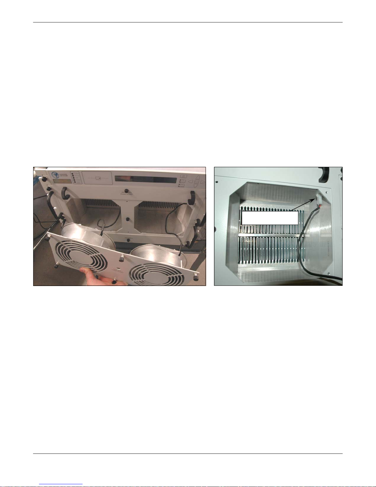
2.1.2 Removable Fan Tray
Six (6) captive thumb screws secure the fan tray to the front of the chassis. Loosen the thumb
screws by rotating them counter-clockwise. Gently slide the fan tray assembly out of the enclosure until there is enough clearance to reach the power plug for each fan. Unplug each
power connector. See Figure 2-3 and Figure 2-4.
UNPLUG POWER
CONNECTORS
Figure 2-3: Removable Fan Tray
Figure 2-4: Unplug connector
A replacement fan tray may be ordered from the factory. Order part number L208545-X.
Check with the factory to ensure the proper version is ordered.
2.1.3 Removable Front Panel
Six (6) captive thumb screws secure the fan tray to the front of the chassis. Loosen the thumb
screws by rotating them counter-clockwise. The power cable for both fans will need to be
disconnected before fully removing the front panel.
2.1.3.1 Phase Adjusters
There are three adjustment screws accessible at the front panel which allow adjustment of
the phase of the SSPA modules within the chassis. The phase adjustment of the 7RU chassis
is set at the factory for optimum output power across the frequency range. In the event that a
module fails and needs to be replaced, the phase of the new module will need to be adjusted
for best performance. See Section 4.3 for directions on adjusting the phase combining.
Operations Manual, 7RU SSPA Chassis 208528 REV F 15
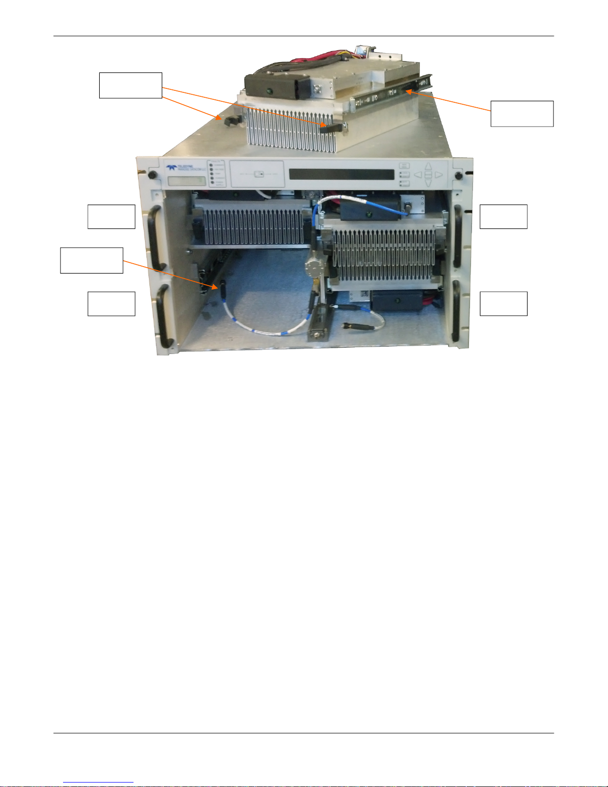
Compression
latches
Rack slide
lock release
Module 2
RF In
connector
Module 4
Module 1
Module 3
Figure 2-5: Slide SSPA Module from Chassis enclosure
2.1.3.2 Access to Removable SSPA Modules
The 7RU chassis houses four SSPA module/heatsink assemblies behind the front panel. The
a system of rack slides allows the module/heatsink assemblies to be removed from the amplifier chassis for maintenance.
A faulted module may be removed from the chassis without taking the amplifier offline. To
identify the faulted module, press the Main Menu key on the front panel, select 1.SysInfo
and press the Enter key. Press the Down Arrow (▼) key seven (7) times to view the operation condition of Module1, Module2, Module3 and Module4. Figure 2-5 shows the location of
each module.
With the front panel removed, uncouple the RF In connector from the faulted module, lift and
turn the compression latches on either side of the module assembly, and slide the unit out of
the enclosure by releasing the slide locks on either side of the module assembly. See Figure
2-5.
A new module/heatsink assembly may be inserted in place of the one removed. Insert the
replacement module/heatsink assembly into the rack slide. Carefully slide the assembly back
into the enclosure. To ensure the module/heatsink assembly is properly seated, lock the
compression latches and gently tug on the handles. The assembly should not slide forward.
Re-couple the RF In connector. Some system phase adjustment may be necessary to ensure
optimum power output. See Section 4.3 for a description of proper system phase adjustment.
16 208528 REV F Operations Manual, 7RU SSPA Chassis
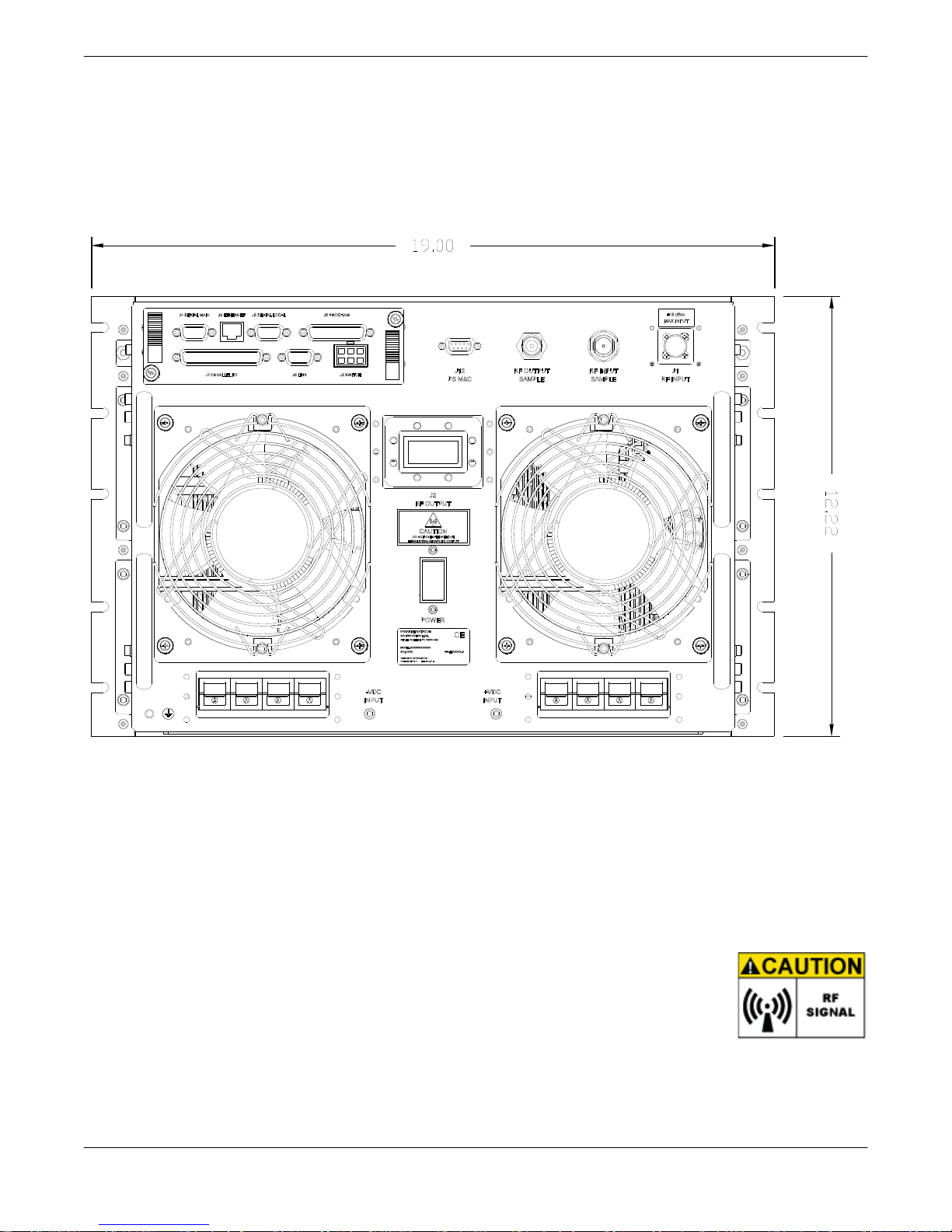
2.2 Rear Panel Features
All cable and waveguide connections are made at the rear panel of the 7RU SSPA Chassis.
The chassis rear panel also features a removable controller card assembly, and individual
removable fan assemblies.
Figure 2-6 shows an outline drawing of the rear panel view.
Figure 2-6: Rear Panel, 7RU SSPA Chassis
2.2.1 RF Input Port (J1) [Type N(F)]
The type N female connector on the top right of the rear panel is used to introduce RF input to
the SSPA.
2.2.2 RF Output Port (J2)
The waveguide flange in the middle of the rear panel is used as the RF
Output. C-Band amplifiers utilize a WR137 waveguide with CPR 137G
flange, while Ku-Band amplifiers use a WR75 waveguide with grooved (PBR
-120) flange. X-Band units employ a WR112 rigid waveguide with a
CPRG112 grooved flange with through holes. S-Band amplifiers use a Type
N (F) connector for the RF Output port. Do not operate the amplifier without having a mating
connection or termination on the RF Output Port. RF Hazard warnings apply.
Operations Manual, 7RU SSPA Chassis 208528 REV F 17
2.2.3 Switch Port (J3) [Molex 43810-0002]
A 6-pin Molex connector header with blind insertion system guides (mates with Molex P/N 3901-2060) is used in a 1:1 Redundancy System to provide switching for the waveguide transfer
switch (RF Switch). Table 2-1 shows the pin-outs for the Switch Port (J3).
Table 2-1: Switch Port (J3) pin outs
Pin # Function / Description
1 +28V Switch Drive Output. 3 Amp over current protection.
2 Switch 1 Position 2 drive
3 Switch 1 Position 1 drive
4 +28V Switch Drive Output. 3 Amp over current protection.
5 Switch 2 Position 2 drive
6 Switch 2 Position 1 drive
2.2.4 Serial Main (J4) [DB9(F)]
A DB9 female connector serves as primary control interface connector. The interface is
re-configurable through the front panel or can be used as a RS-232 or R-485 interface (2 or 4
wires). The RS-485 TX and RX pairs must be twisted for maximum transmission distance. A
user-configurable 120-ohm termination resistor is provided on the same connector. Table 2-2
shows the pin outs for the Serial Main (J4) connector. A form C summary alarm is also
present on J4. It is noted as a service request and occupies pins 6, 7 and 8.
Table 2-2: Serial Main (J4) pin outs
Pin # Function / Description
1 RS485 TX+ (HPA Transmit +)
2 RS485 TX- (HPA Transmit -)/RS232 TX
3 RS485 RX- (HPA Receive -)/RS 232 RX
4 RS485 RX+ (HPA Receive +)
5 GND
6 Service Request 1 Form C relay NC contact (Closed on HPA Summary Fault)
7 Service Request Common Form C relay common contact
8 Service Request 2 Form C relay NO contact (Opened on HPA Summary Fault)
9 120 ohm termination (must be connected to pin 4 to enable termination)
2.2.5 Serial Local (J5) [DB9(M)]
This DB9 male connector is used in advanced system integration and for system debugging
purposes. Leave unconnected unless specified otherwise.
2.2.6 Program Port (J6) [DB25(M)]
A DB25 male connector is used to provide in-field flash re-programmability for the amplifier
controller card. In order to reload controller board firmware, connect this port to a PC Parallel
port using a straight through cable. Contact support before proceeding further.
18 208528 REV F Operations Manual, 7RU SSPA Chassis
2.2.7 Parallel I/O Port (J7) [DB37(F)]
A DB37 female type connector, the Parallel I/O Port contains a series of contact closures for
monitoring SSPA faults as well as opto-isolated inputs for controlling some SSPA functions.
Inputs react on the closure to ground. The minimal closure time is 50 mS. See Table 2-3 for a
description of the pin outs for this connector.
Table 2-3: Parallel connector (37 socket D connector)
Pin # Function / Description
1 Closed on Power Supply Fault Form C relay NC
2 Opened on Power Supply Fault Form C relay NO
20 Power Supply Fault Common
21
22
3 Auxiliary Fault\Auto-Manual Common
4 Closed on Mute. Form C Relay NC
5 Opened on Mute. Form C Relay NO
23 Mute Status Common
24 Closed on BUC Fault. Form C Relay NC
25 Opened on BUC Fault. Form C Relay NO
6 BUC Fault Common
7 Closed on High Temperature Fault. Form C Relay NC
8 Opened on High Temperature Fault. Form C Relay NO
26 High Temperature Fault Common
27
28
9 Regulator Low Voltage Fault\Standby-Online Common
10 Closed on DC Current Low Fault. Form C Relay NC
11 Opened on DC Current Low Fault. Form C Relay NO
29 DC Current Low Fault Common
30 Closed on Low Forward RF Fault. Form C Relay NC
31 Opened on Low Forward RF Form C Relay NO
12 Low Forward RF Fault Common
16 Auto/Manual toggle input. 50mS Closure to isolated ground to activate
17 Mute/Unmute toggle input. 50mS Closure to isolated ground to activate
18 Auxiliary Fault input. 50 ms minimum response time
35 HPA Standby input. 50mS Closure to isolated ground to activate
36 Local/Remote toggle. 50mS Closure to isolated ground to activate
37 Fault clear. 50mS Closure to isolated ground to activate
19 Isolated Signal Ground
15 +5V Isolated Power 20 mA
13, 32 +28V Auxiliary Power 1A
14, 33 Chassis Ground
1. Standalone mode. Closed on Auxiliary Fault
2. 1:1 Redundancy Mode. Closed on Automatic switchover mode. Form C relay NC
1. Standalone Mode. Opened on Auxiliary Fault
2. 1:1 Redundancy Mode. Closed on Manual switchover mode. Form C relay NO
1. Standalone mode. Closed on Regulator Low Voltage Fault
2. 1:1 Redundancy Mode. Closed on HPA Standby. Form C relay NC
1. Standalone Mode. Opened on Regulator Low Voltage Fault.
2. 1:1 Redundancy Mode. Closed on HPA Online Mode. Form C relay NO
Operations Manual, 7RU SSPA Chassis 208528 REV F 19
2.2.8 Link Port (J8) [DB9(F)]
The 9-pin male connector J8 Link Port is used to link a SSPA with other units in a redundant
system in order to pass online/standby status information between them. Leave unconnected
unless specified otherwise.
2.2.9 Ethernet Port (J9) [RJ45]
This is a RJ45 connector with integrated magnetics and LEDs. This port becomes the primary
remote control interface when the Interface option is selected to “IPNet” as described in
Section 7.6.1.2. This feature allows the user to connect the SSPA to a 10/100 Base-T Local
Area Network and have full-featured Monitor & Control functions through a web interface. See
Table 2-4 for Ethernet port pin outs.
Table 2-4: Ethernet Port (J9) pin outs
Pin # Function / Description
1 TX+
2 TX-
3 RX+
6 RX-
4,5,7,8 GND
Note: IP address, Gateway address, Subnet mask, IP port and IP Lock
address needs to be properly selected prior to first use (see Appendix A
for details).
LED lamps on the connector indicate network status. A steady Green light indicates a valid
Ethernet link; a Yellow LED flashes during any data transfer activity (on both Transmit and
Receive paths).
2.2.10 Power Supply M&C (J12)
The DB9 connector is connected to the 3RU power supply chassis. The SSPA monitors the
status of the power supply chassis and alarms in the event of a power supply module failure.
Due to the nature of the N+1 redundant power supply, a failure will not take the amplifier off
the air.
2.2.11 Input Sample Port (Optional)
An optional RF input sample port is located to the left of the J1 RF Input connector on the rear
panel. This port provides a -10 dBc coupled sample of the RF input signal. It is a type N
female connector.
20 208528 REV F Operations Manual, 7RU SSPA Chassis
2.2.12 Output Sample Port
The Output RF Sample Port, which is a type N female connector, is located to the right of the
J12 PS M&C connector on the rear panel. This port provides a -40 dBc coupled sample of the
RF output signal. A calibration sticker is located beneath the connector.
2.2.13 Power Switch
The rocker-type power switch is located near the center of the rear panel, beneath the (J2)
RF output.
2.2.14 DC Input Quick Connect Ports
Power to the 7RU SSPA Chassis is supplied by a separate power supply chassis (See Section 2.3). The power supply’s DC output is provided by cables permanently attached to the
Power Supply that connect to the SSPA’s internal bus-bar via a series of quick-disconnect
high current in-line connectors.
Simply connect the mating DC output cable quick-disconnect connectors to the positive and
negative power connecters at the rear of the chassis.
2.2.15 Removable Fan Assemblies
The exhaust fans on the rear panel are each secured by four (4) captive thumb screws. To
remove, loosen the screws and carefully remove the fan assembly from the chassis. Unplug
the fan power cord from the connector. Replace with part number L206332-2.
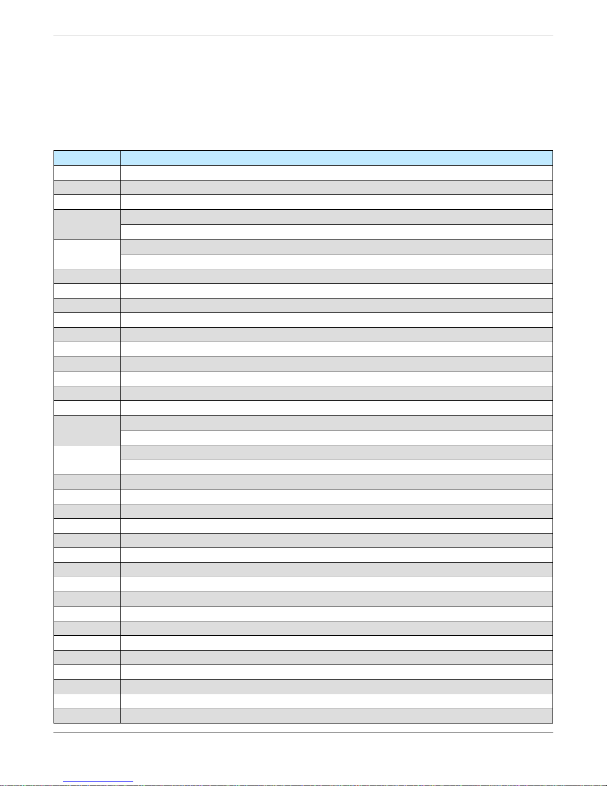
2.2.16 Removable Controller Card Assembly
The controller card assembly is located at the rear of the SSPA and includes the Switch (J3),
Serial Main (J4), Serial Local (J5), Programming (J6), Parallel I/O (J7), Link (J8) and Ethernet
(J9) ports.
To remove this card assembly, loosen the two restraining thumbscrews at the top left and
bottom right of the assembly. See Figure 2-7. Slide the assembly straight back from the
cavity, as shown in Figure 2-8. This exposes the SSPA module programming connectors.
Figure 2-7: Loosen the two retaining
thumbscrews.
Operations Manual, 7RU SSPA Chassis 208528 REV F 21
Figure 2-8: Remove the card to access
the programming connectors.
2.3 Redundant Power Supply Chassis
A separate power supply chassis is used to provide redundancy of the power supply to the
7RU SSPA chassis. The power supply is configured with a parallel set of modules. All of the
modules are active and share the load current supplied to the amplifier. The power supply
module current capacity is chosen such that at least one extra module is included over the
amplifier’s current requirement. This is to say that the power supply is n+1 redundant. The
amplifier will continue to operate normally in the presence of one power supply module failure.
The power supply modules are all hot swappable from the front panel. Therefore, if there ever
is a power supply module failure, there is no need to remove the entire power supply chassis.
The failed module is simply removed via the front panel. The power supply module removal
can be performed with the system powered. This is to say that the modules are “hot swappable”.
2.3.1 1RU (four-module) N+1 Redundant Power Supply
The 1RU power supply shelf can be mounted directly below and adjacent to the amplifier
chassis. The 1RU power supply chassis is configured as an N+1 redundant, hot swappable
power source utilizing four 2.5 kW power modules. In the event of a single power module failure, the amplifier system will not fail.
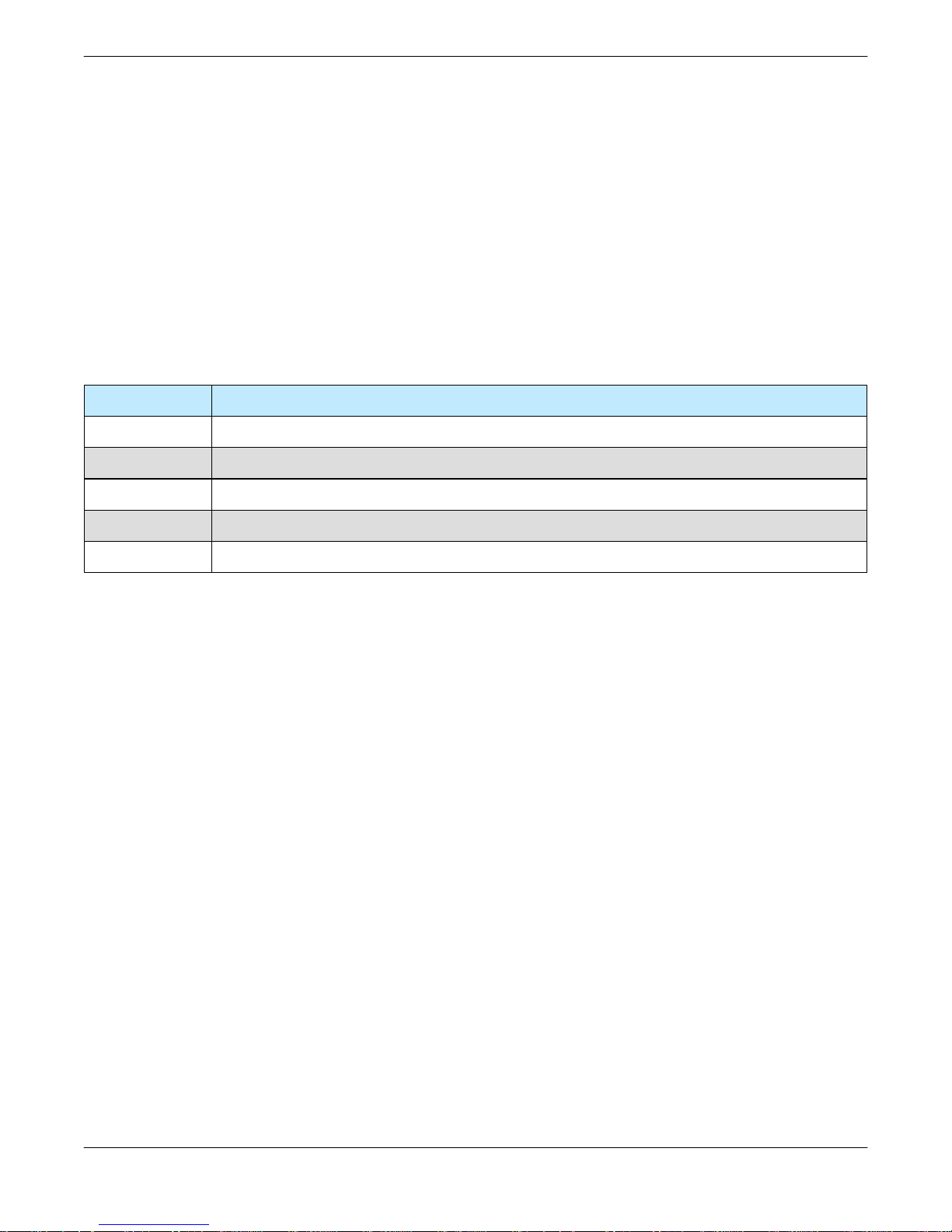
2.3.1.1 AC Mains Connection
In keeping with the redundant architecture of the power supply, there are individual AC inputs
for each power supply module. DC Outputs are in a bus bar configuration. See Figure 2-9.
+ -
DC Outputs
Figure 2-9: 1RU Power Supply AC Line Inputs/Outputs
The standard 24V AC input configuration for the 2.5 kW power supply is 100-240 VAC single
phase, 47-63 Hz, 0.99 power factor per module. A separate AC input transformer could feed
each AC input.
The wiring identification is as follows:
• L1 - Brown
• Chassis Ground - Green/Yellow
• L2/N - Blue
22 208528 REV F Operations Manual, 7RU SSPA Chassis
+ -
DC Outputs
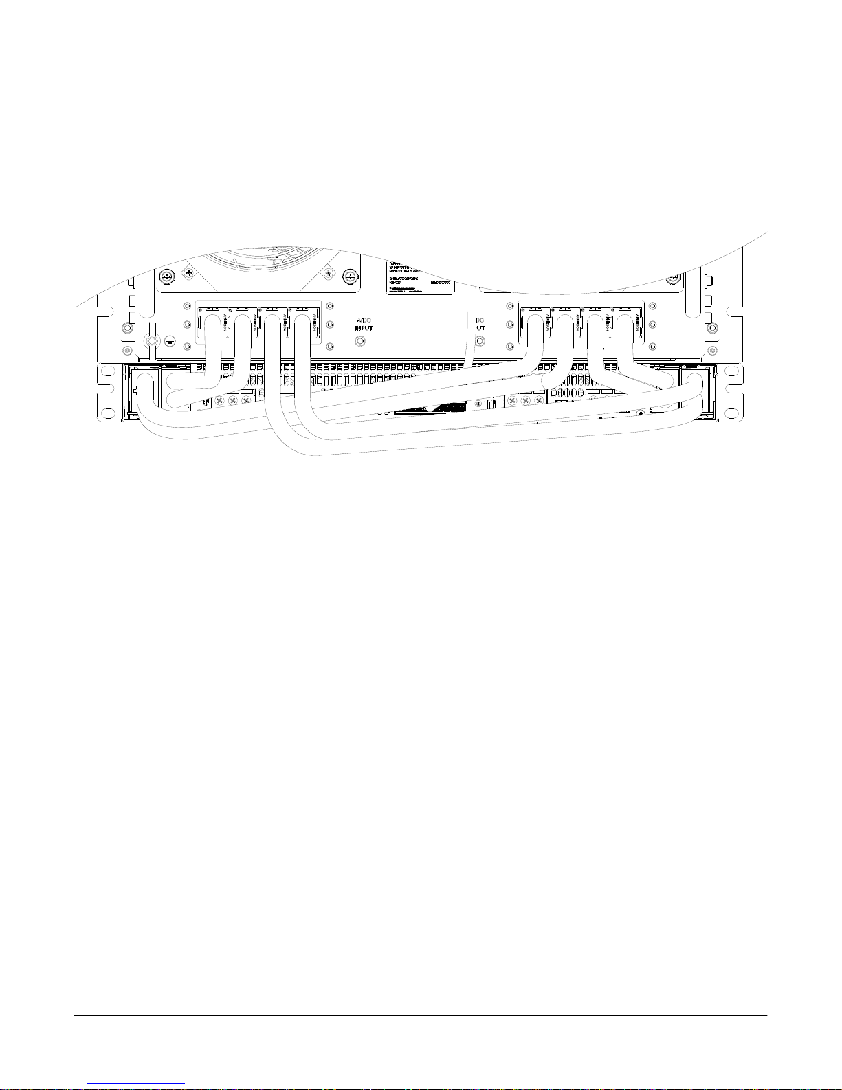
2.3.1.2 DC Output Connection
The DC output is provided by eight (8) sets of cables attached to the Power Supply DC output
buss bars that connect to the SSPA via a series of quick-disconnect high current in-line
connectors.
Connect the mating DC output cable quick-disconnect connectors to the positive and negative
power connecters at the rear of the chassis. See Figure 2-10.
Figure 2-10: DC Output Cable, Quick-Connect to Rear of Amplifier
2.3.1.3 Power Supply Alarm Connection
Each power supply module has an alarm output. The power supply alarms are monitored by
the SSPA’s monitor and control system. This provides for local and remote alarm reporting in
the event of a power supply module failure. The module alarm outputs are open-collector
signals with a low level = fault logic level. Under normal operation the alarm outputs are in a
high impedance state.
Using cable L202583-1, connect the Alarms Port of the 1RU Power Supply to Port J12 of the
accompanying 7RU SSPA Chassis.
2.3.1.4 Alarm Configuration at the SSPA Chassis
The power supply alarms may be monitored via the SSPA Chassis front panel menu. See
Section 3.1.2.
A failure of one of the power supply modules results in a minor fault, and the Power Supply
Fault indicator on the front panel of the SSPA Chassis will light and the System Information
screen on Page 2 of the Main menu will indicate a Power Supply Fault. To clear the fault, replace the faulted power supply module.
Operations Manual, 7RU SSPA Chassis 208528 REV F 23
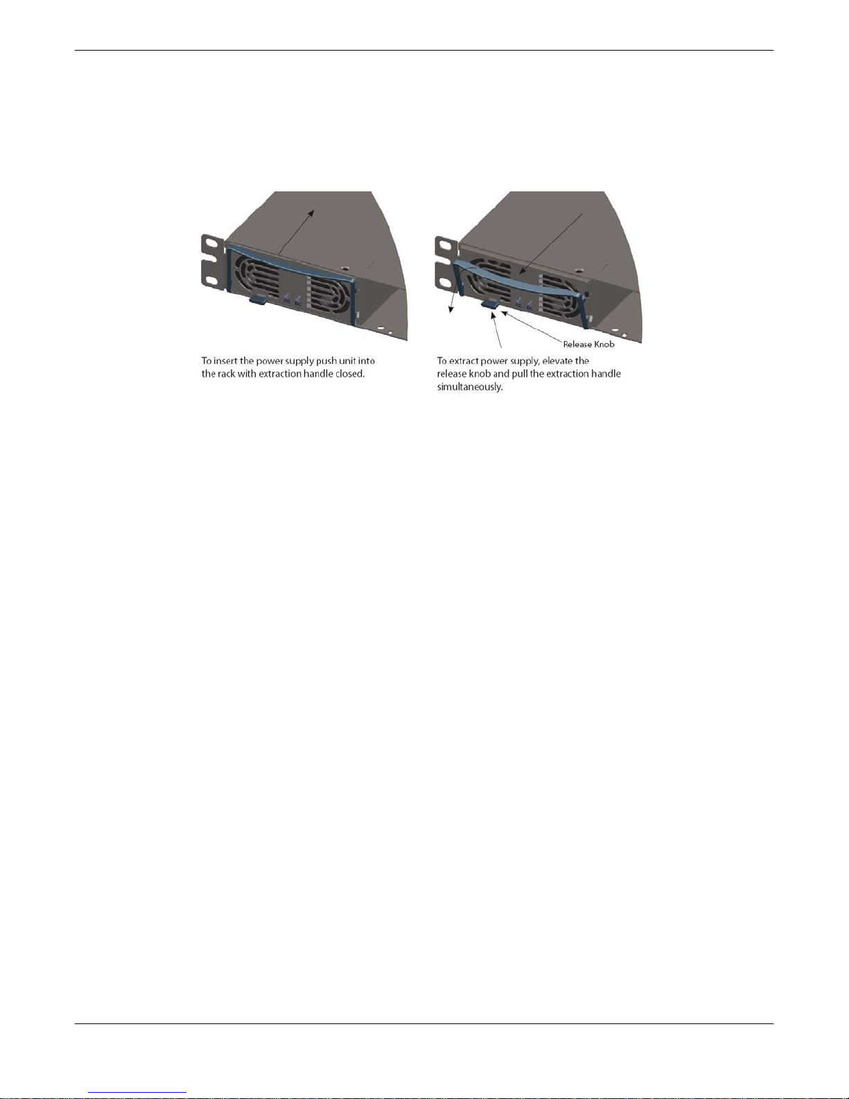
2.3.1.5 Power Supply Module Removal/Replacement
A failed module can be changed without ever taking the system out of service. Simply lift the
release knob and pull the extraction handle until the module slides from the shelf. Slide the
replacement module into the empty slot until the module is flush with the front of the shelf.
See Figure 2-11.
Figure 2-11: 1RU Power Supply Module Insertion/Extraction
24 208528 REV F Operations Manual, 7RU SSPA Chassis
2.3.2 Dual 1RU (four module) Power Supply Option
The 600W Ku-Band 7RU SSPA requires two (2) 1RU power supplies; one 12V supply and
one 28V supply. See Figure 2-12.
12V Supply
28V Supply
Figure 2-12: Dual 1RU Power Supply Option
Each power supply has a single phase, universal AC input ranging from 90-264 VAC, 47-63
Hz and is power factor corrected to 0.99.
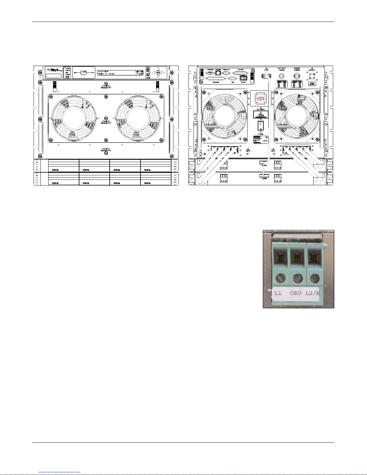
2.3.2.1 AC Mains Connection
The power supply chassis has a dual feed AC architecture. Power
module slots 0 & 1 are supplied via AC Feed 1 and power module
slots 2 & 3 are supplied via AC Feed 2. The AC connections on the
shelf are made via rear accessed compression style terminal blocks.
See Figure 2-13.
Connect the first line/hot to L1, the second line or neutral to L2/N
and the AC ground to GND. These terminal blocks will accept up to
a maximum of 10 AWG wire, and should be torqued to 6 in-lbs
Figure 2-13:
Terminal block
2.3.2.2 DC Output Connection
The DC output is provided by eight (8) sets of cables attached to the Power Supply DC output
buss bars that connect to the SSPA via a series of quick-disconnect high current in-line
connectors. As shown in Figure 2-12, the outputs of the 12V supply plug into the two (2) inputs at the far left and far right of the amplifier.
2.3.2.3 Power Supply Alarm Connection
The power supply alarm cable used with the dual 1RU power supply option is L210747-1, and
connects between the Alarms Port of each of the power supplies and Port J12 of the 7RU
amplifier. The cable connectors are labeled for easy identification.
Operations Manual, 7RU SSPA Chassis 208528 REV F 25
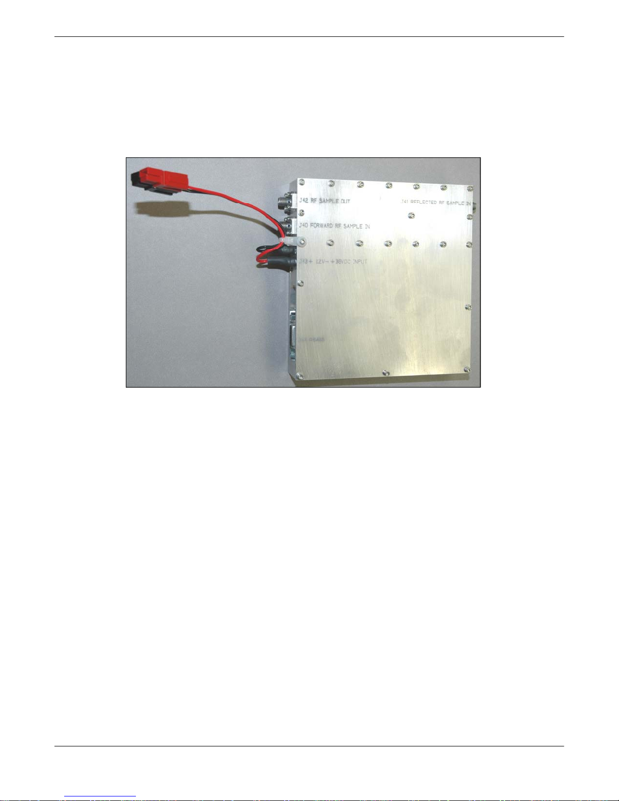
2.4 Forward Power Detector
The Forward Power Detector module allows the user to introduce a sample of the unit or
system Forward RF power from the waveguide output. The detector box circuitry will measure
the amount of RF power present in the sample, with a dynamic range of 20 dB starting at the
maximum RF output. The following connections are required in order to monitor the output
power from the front panel menu of the SSPA chassis. See Figure 2-14.
Figure 2-14: Forward Power Detector Module
2.4.1 J40 Forward RF Sample In [SMA (F)]
A Forward RF Sample may be fed into port J40 of the detector box from a cross-guide
coupler on the RF output.
2.4.2 J44 RS-485 Connector [DB9 (F)] (209922)
This DB9 female connector serves as the primary RS-485 (2 or 4 wires) serial remote control
interface connector. The detector box is included in the serial chain along with the amplifiers
in the system.
2.4.3 Quick Connect Power
The Forward Power Detector module is powered via the J7 Parallel Port of the SSPA, when
operating a standalone unit. In system configurations, the Forward Power Detector module is
powered via a Detector Power Cable that also links to Port J7 between two or more units.
26 208528 REV F Operations Manual, 7RU SSPA Chassis
Section 3: Operation
via Front Panel Menu
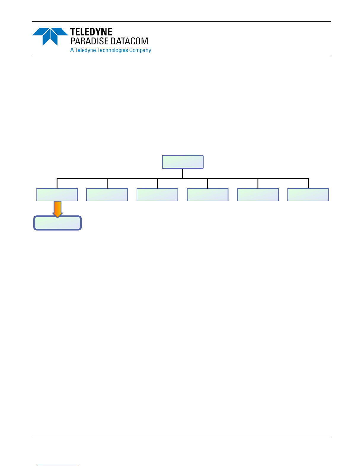
3.0 Main Menu
Figure 3-1 shows the Main Menu Structure hierarchy. There are six main levels of menu
selections.
1. Sys.Info - System Information menu sublevel
2. Com.Setup - Serial Communication related settings
3. Operation Setup - System operation related settings
4. Fault Monitoring Setup - Fault handling settings
5. Options - Backup/restore and password settings
6. Redundancy - Switching and standby settings
Main Men u
2.Com Setup1.Sys Info 3.Operation 4.Flt. Setup 5.Options
To Sys Info Page 1
6.Redundancy
Figure 3-1: Main Menu, Top Level
The menu tree is accessed by selecting the [MAIN MENU] key on the front panel. Navigation
through the menu structure is handled by using the Up [▲], Down [▼], Left [◄], and Right
[►] arrow keys and the [ENTER] key to select from the items shown in the front panel display.
For menus where an actual numerical value must be entered, the Up [▲] and Down [▼] arrows change the number by factors of 10; the Left [◄] and Right [►] arrows change the number in increments of 1.
Operations Manual, 7RU SSPA Chassis 208528 REV F 27
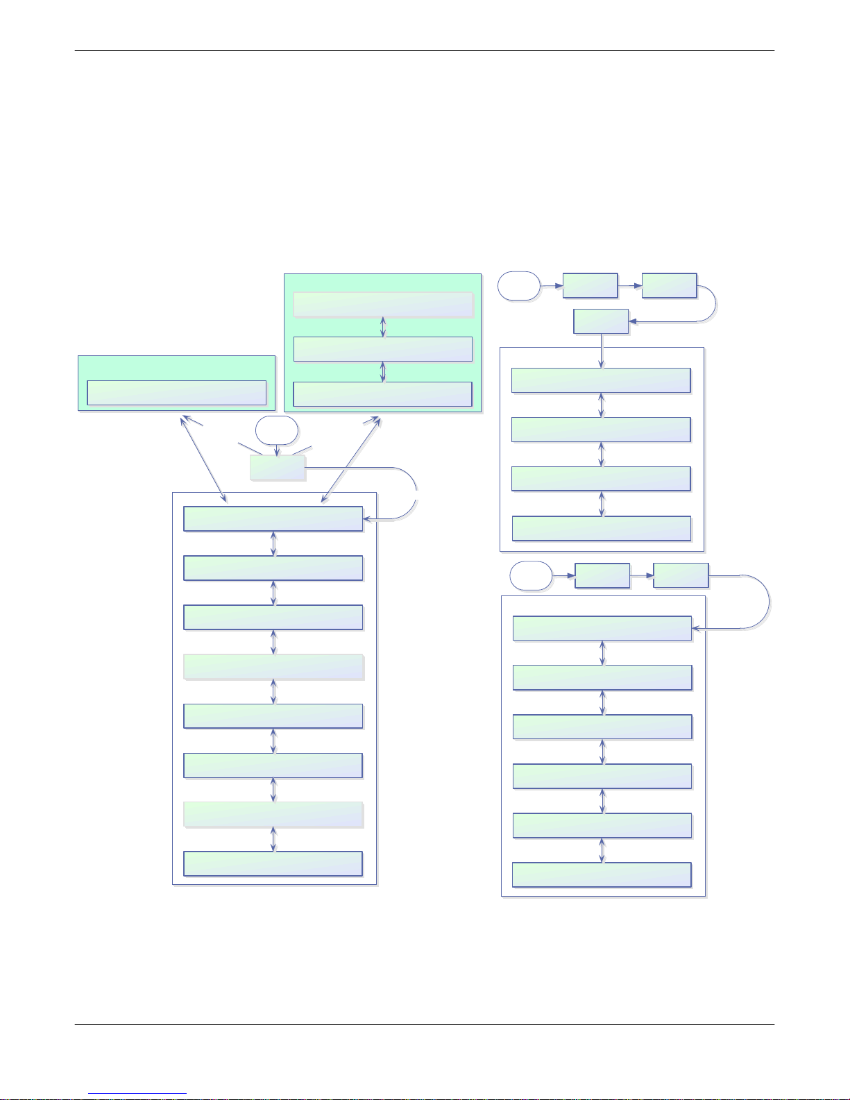
3.1 System Information Sub-Menu
The informative sublevel menu structure contains several pages, shown in Figure 3-2. The
user can also browse among these pages by navigating the cursor around the menu fields
and pressing the Enter button on the keypad. Note that this function will not work if the "Fault
Latch" option is selected.
In a N+1 configuration, the Master unit default System Information page is as described in
Section 3.1.16; the default page for Slave units is as described in Section 3.1.17. In non-N+1
configurations, the default page is as described in Section 3.1.1.
N+1 Slave unit sys t em info
N+1 Slave Unit
Unit operation under sys tem control
S
l
a
v
e
U
Atten.(dB):XX.X FrwrdRF(dBm):XX.X
Ala rms:XXXXXX Ref.RF(dBm):XX.X
PS:XXXXXX LowRF:XXXXXX Fan:XXXXXX
AUX:XXXXXX VSWR:XXXXXX BUC:XXXXXX
RFSW1:XXXXXX State:XXXXXX Prior:XXXX
RFSW2:XXXXXX Mute:XXXXXX Po lSel:XXXX
Prtcl:XXXXXX Int r f c :XXXXX Buzzer:XXX
Baud:XXXXX Addrs.:XXX Latch:XXX
Main
n
System Info Menus
Menu
i
t
s
1.Sys.Info
N+1 Master unit system info
Cabinet Temp(C):XXX Cabinet Fan:XXXXXX
N+1 Arr.S ize:XXX N+ 1 Alarms:XXXXXX
N+1 Address :XXX N+1 Stat e:XXXXXX
Atten.(dB):XX.X SysRFOut(dBm):XX.X
AutoGain(dB):XX.X Ref.RF(dBm):XX.X
y
l
n
o
t
i
n
U
r
e
t
s
a
M
Non N+1 Uni ts
Main
Menu
IPAdd r:XXX.XXX.XXX.XXX MAC:XXXXXXXXXX
CommunityGet:XXXXXXXXXXXXXXXXXXXXX
CommunitySet:XXXXXXXXXXXXXXXXXXXXX
Web Password:XXXXXXXXXXXXXXXXXXXXX
Main
Menu
3.Operation 5.IPSetup
1.IPInfo
IP Setup Menus
Subnet:XXX.XXX.XXX.XXX Port:XXXXX
Gateway:XXX.XXX.XXX.XXX
LockIP:XXX.XXX.XXX.XXX
3.Operation
SSPA Firmw are Info
ParadiseDatacom Digicore XM128-
Vers io n X. XX (XX ) Built YY, MMM D D
SSPAID:XXXXXXXXXXXXXXXXXXXX
UserInfo:XXXXXXXXXXXXXXXXXXXX
1.Info
Mode:XXXXXXX Ctrl:XXXXXX Unit:XXXX
Stby:XXXX Switch:XXXXX FSpeed:XXX
PS1(V):XX.X Boost1(V):XX.X DC(A):XX.X
PS2(V):XX.X Boost2(V):XX.X
Regulator:XXXXXX Temperat ur e:XXXXXX
DCCurrent:XXXXXX Temp.( C) :XXX
Module1:XXXXXX Module3:XXXXXX
Module2:XXXXXX Module4:XXXXXX
Figure 3-2: System Information Sub-Menu
Note: If the "Fault Latch" option is enabled, pressing the "Enter" button will clear all
system faults.
28 208528 REV F Operations Manual, 7RU SSPA Chassis
Firmware:XXXXXXXXXX Modul e1
ID:XXXXXXXXXXXXXXXXXXXXXX
Firmware:XXXXXXXXXX Modul e2
ID:XXXXXXXXXXXXXXXXXXXXXX
Firmware:XXXXXXXXXX Modul e3
ID:XXXXXXXXXXXXXXXXXXXXXX
Firmware:XXXXXXXXXX Module 4
ID:XXXXXXXXXXXXXXXXXXXXXX

3.1.1 Sys Info Page 1
This is the amplifier main status information page. The page shows:
• Amplifier attenuation measured in dB ( Atten. (dB): XX.X) with accuracy of 0.1dB;
• Forward RF Power, measured in either dBm with resolution of 0.1dBm, or Watts
with a resolution of 0.1 Watts
• Alarms presence, "FAULT!" or "None" will be displayed depending on the state of
unit;
• Reflected RF Power, measured in either dB with resolution of 0.1dBm, or Watts
with a resolution of 0.1 Watts. Displays “N/A” if unavailable.
3.1.2 Sys Info Page 2
This page shows a variety of alarm states which may be present within the unit. Fault values
could be "Fault", "Normal" and "N/A"
• PS - power supply alarm, displays "Normal" if amplifier power supplies are normally
operational and "Fault" if one or more power supplies failed.
• LowRF - low RF fault;
• Fan - cooling system failures;
• Aux. - Auxiliary fault condition;
• VSWR - High Reflected power fault;
• BUC - Block Up converter fault.
If the fault condition doesn't apply to the amplifier configuration it will display "N/A" for "Not
Available".
3.1.3 Sys Info Page 3
This page displays miscellaneous information related to the redundancy operation and the
unit mute status.
• RFSW1 - state of RF switch 1, possible values - "Pos1" Pos2" "N/A", "Fault";
• RFSW2 - state of RF switch 2, possible values - "Pos1" Pos2" "N/A", "Fault";
• State - Unit online state, possible values "Online", "Standby";
• Mute - Amplifier mute state, possible values "Clear", "Set";
• Prior - Priority polarization select (1:2 Mode Only);
• PolSel - Current Polarization output (1:2 Mode Only)
3.1.4 Sys Info Page 4
This page displays various amplifier settings:
• Prtcl. - unit’s active remote control protocol. The value can be set to "Terminal", if
terminal mode protocol is currently active and "Normal" for string I/O type protocol.
• Baud - selected baud rate for remote control serial port. Selection: "2400", "4800",
"9600", "19200", "38400";
• Intrfc. - selected serial port interface. Selection: "RS232", "RS485".
Operations Manual, 7RU SSPA Chassis 208528 REV F 29

• Addrs. - Amplifier’s remote control network address. Value could be in range from 0
to 254. Note: address 255 is reserved for global calls and shouldn't be used for an
individual unit’s addressing.
• Buzzer - Audible alarm availability. Displays "Dis" if disabled; "Enb" if enabled.
• Latch - Fault latch option selection. Displays "Dis," if disabled; "Enb" if enabled.
3.1.5 Sys Info Page 5
Page 5 shows settings related to the Amplfier 1:1 Redundant System operation.
• Mode - indicates unit operational mode. Value can be set to "1:1" for 1:1
redundancy mode and "Stdaln" for stand alone mode;
• Stby. - shows unit standby state selection. "Hot" for hot standby operation (amplifier
retains unmuted state during standby period) and "Cold" for cold standby (unit
always mutes itself in standby mode and unmutes when switched back on-line).
• Ctrl. - shows amplifier control style. "Local" - both local and remote control are
supported and "Remote" when only remote control provided (keypad locked);
• Switch - indicates switching style. "Auto" for automatic fault tracking/switching and
"Manual" if redundancy switching is provided by operator.
• Unit - redundancy topological factor. "HPA1" for unit connected to RF switch ports 1
or 4 (Online Position 1 of the RF switch). "HPA2" for unit connected to RF switch
ports 2 or 3 (Online Position 2 of the RF switch).
3.1.6 Sys Info Page 6
This page shows the status of the unit’s internal power supplies
• PS1(V) - main power supply 1 output voltage with resolution of 0.1V. Normal output
voltage should be in range of 11 to 13 V.
• PS2(V) - main power supply 2 output voltage.
• Boost1(V) - booster power supply 1 output voltage with resolution of 0.1V. Normal
range 24 to 30 V (typical 28V);
• Boost2(V) - booster power supply 2 output voltage.
• DC (A) - total DC current draw by RF modules from main power supply. Value
varies depending on the power level of the unit. If the amplifier is muted, current
normally drops to within the 0 to 5 A range.
3.1.7 Sys Info Page 7
This page shows RF module related faults and conditions.
• Regulator - RF module regulator low voltage fault. Values - "Fault" or "Normal";
• DC Current - low DC current fault. Values -"Fault" or "Normal";
• Temperature - high temperature fault. Values - "Fault" or "Normal";
• Temp.(C) - internal RF module plate temperature in Celsius.
30 208528 REV F Operations Manual, 7RU SSPA Chassis
 Loading...