

Teledyne 760 PLUS User Manual
TELEDYNE
HASTINGS
INSTRUMENTS
INSTRUCTION MANUAL
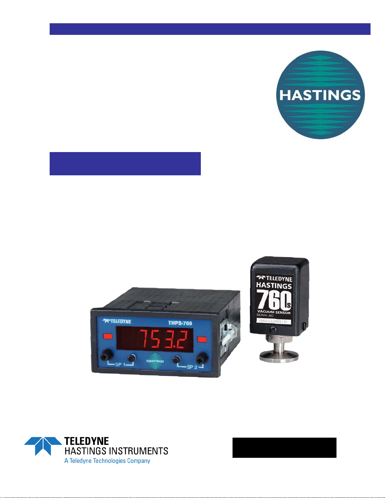
760 PLUS
VACUUM GAUGE
ISO 9001
CERTIFIED

Manual Print History
The print history shown below lists the printing dates of all revisions and addenda created for this
manual. The revision level letter increases alphabetically as the manual undergoes subsequent updates.
Addenda, which are released between revisions, contain important change information that the user
should incorporate immediately into the manual. Addenda are numbered sequentially. When a new
revision is created, all addenda associated with the previous revision of the manual are incorporated into
the new revision of the manual. Each new revision includes a revised copy of this print history page.
Revision A (Document Number 147-0497)....................................................................... January 1998
Revision B (Document Number 147-012000)................................................................... January 2000
Revision C (Document Number 147-082002)....................................................................August 2002
Revision D (Document Number 147-092002) .............................................................September 2002
Revision E (Document Number 147-112003) .............................................................. November 2003
Revision F (Document Number 147-022004) ...................................................................January 2004
Revision G (Document Number 147-082005) ...................................................................August 2005
Revision H (Document Number 147-092005) .............................................................September 2005
Revision J (Document Number 147-102007) ................................................................... October 2007
Revision K (Document Number 147-082010) ...................................................................August 2010
Visit www.teledyne-hi.com for WEEE disposal guidance.
Hastings Instruments reserves the right to change or modify the design of its equipment without
any obligation to provide notification of change or intent to change.
Manual: 147-082010_HPM-760-Plus-Vacuum-Gauge Page 2 of 16

Table of Contents
1. GENERAL INFORMATION............................................................................................................................................4
1.1. FEATURES ..............................................................................................................................................................4
1.2. SPECIFICATIONS..................................................................................................................................................... 5
2. INSTALLATION.......................................................................................................................................................... 6
2.1. RECEIVING INSPECTION ......................................................................................................................................... 6
2.2. PIEZO TRANSDUCER (760S) INSTALLATION ........................................................................................................... 6
2.3. POWER SUPPLY/DISPLAY INSTALLATION............................................................................................................... 7
2.3.1. Power Supply/Display Cables and Wiring....................................................................................................... 7
3. OPERATING INFORMATION..................................................................................................................................8
3.1. GENERAL ............................................................................................................................................................... 8
3.2. PIEZO TRANSDUCER INPUT POWER........................................................................................................................ 9
3.3. PIEZO TRANSDUCER OUTPUT SIGNAL ....................................................................................................................9
3.4. POWER SUPPLY/DISPLAY INPUT POWER ................................................................................................................ 9
3.5. THPS-760 POWER SUPPLY PHYSICAL LAYOUT ..................................................................................................... 9
3.5.1. Front Panel (Refer to page 19, 7.1.1 for physical layout.)............................................................................... 9
3.5.2. Rear Panel...................................................................................................................................................... 10
3.6. POWER SUPPLY RELAY SET POINT ADJUSTMENT ................................................................................................ 10
3.7. PRESSURE MEASUREMENTS................................................................................................................................. 11
4. CALIBRATION.......................................................................................................................................................... 12
4.1. HASTINGS 760 PLUS PIEZO TRANSDUCER ZERO AND SPAN ADJUSTMENT ........................................................... 12
4.2. HASTINGS 760S OPTION-5 TRANSDUCER ZERO AND SPAN ADJUSTMENT ............................................................ 12
5. MAINTENANCE........................................................................................................................................................ 13
5.1. POWER SUPPLY/DISPLAY AUTHORIZED MAINTENANCE ...................................................................................... 13
5.2. PIEZO TRANSDUCER AUTHORIZED MAINTENANCE .............................................................................................. 13
6. WARRANTY.............................................................................................................................................................. 14
6.1. WARRANTY REPAIR POLICY ................................................................................................................................14
6.2. NON-WARRANTY REPAIR POLICY ....................................................................................................................... 14
7. DIAGRAMS AND DRAWINGS............................................................................................................................... 15
7.1. FRONT PANEL ...................................................................................................................................................... 15
7.2. REAR PANEL ........................................................................................................................................................ 15
7.3. MOUNTING........................................................................................................................................................... 16
7.4. PANEL MOUNTING ............................................................................................................................................... 16
Manual: 147-082010_HPM-760-Plus-Vacuum-Gauge Page 3 of 16

1. General Information
This manual contains technical and general information relating to the installation, operation, and
calibration of the Hastings 760 Plus vacuum gauge which is comprised of a piezo vacuum transducer
(760s) and power supply/display.
The 760s piezoresistive type transducer has one side of its diaphragm evacuated to a low reference
pressure then sealed to produce an absolute pressure signal output. This output signal is linearproportional to the applied pressure and is independent of gas composition.
The power supply/display provides 24 VDC excitation power for the 760s transducer and a four digit
dual setpoint meter relay for monitoring, measurement and control applications.
For best performance, this instrument should be operated with the appropriate Hastings accessory
items. Attempting to use a Hastings product with other manufacturers equipment may result in damage
to all equipment.
1.1. Features
Piezo Vacuum Transducer (760s):
• Linear voltage or current output
• Absolute pressure measurement, independent of gas composition
• Zero and span, adjustable
• Compact size, 1.5” x 1.5” x 3”
• 0.1 - 1000 Torr range
• Stand alone operation with 15 - 30 VDC input
• All wetted materials 316 stainless steel
• Optional 3-1/2 digit, LCD display
Power Supply/Display:
• Excitation output for use with Hastings 760S piezo vacuum transducer
• 4 1/2-digit high efficiency red LED display
• Two control relays, SPDT, 2 A (max) @ 240 VAC (max)
• Relay set point, set manually from front panel
• 120/240 VAC input power (no hardware settings required)
• Front panel (SP1, SP2) annunciators (LED’S)
• 1/8 DIN case, panel mounting
Manual: 147-082010_HPM-760-Plus-Vacuum-Gauge Page 4 of 16

1.2. Specifications
Piezo Vacuum Transducer (760s):
Accuracy ......................................................................................................± 0.25% FS* (760 Torr)
Operating pressure ............................................................................................. 1000 Torr (nominal)
Maximum over pressure.......................................................................................... 2300 Torr(45 psi)
Operating temperature ............................................................................................................. 0-50°C
Input voltage .....................................................................................................................15-30 VDC
Input power............................................................................................ 15 mA @ 24 VDC (no load)
Output impedance................................................................................................... 1k ohm minimum
Output signal options:
Option-01 ....................................................................................................... 0-1000 Torr @ 0-5 VDC
Option-02 Std. .............................................................................................. 0-1000 Torr @ 0-10 VDC
Option-03......................................................................................................... 0-1000 Torr @ 2-10 mA
Option-04......................................................................................................... 0-1000 Torr @ 4-20 mA
Option-05.......................................................................0-1000 Torr @ 5 or 10 VDC w/digital display
Size........................................................................................................................ 1.5”x 1.5”x 2.875”
Wetted material(s).................................................................................................... 316 stainless steel
Power Supply/Display:
Digital display.......................................................................................... ± 0.05% of reading ± 1 digit
Temperature coefficient ..................................................................................................< 80 ppm/°C
Input power.............................................................................. 120 or 240 volts AC, 50 ma, 50/60 hz
Output power .....................................................................................24 VDC no regulated @ 30 mA
Input signal......................................................................................................... 0-10 VDC (nominal)
Relay(s) .......................................................................................................... 2A @ 240 VAC form C
Size............................................................................................................................ 1.9”x 3.8”x 4.6”
* Accuracy 0.25% FS (calibration based on a 0.15% RDG standard)
Manual: 147-082010_HPM-760-Plus-Vacuum-Gauge Page 5 of 16
 Loading...