

Teledyne 7120 User Manual
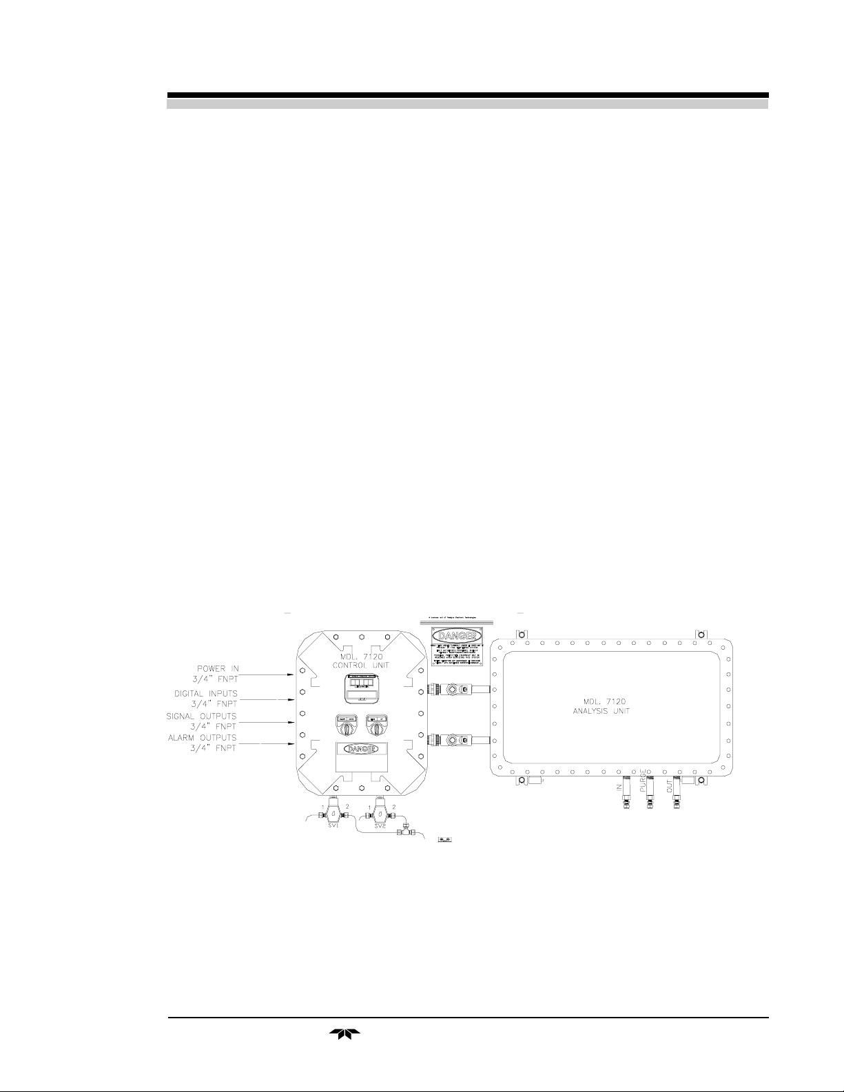
Table of Contents
OPERATING INSTRUCTIONS
Model 7120
Photometric IR Analyzer
Table of Contents
Explosion Proof for
Class I, Division I, Groups B, C, D
Teledyne Analytical Instruments
i

Model 7120 Photometric Analyzer
Table of Contents
1 Introduction
1.1 Overview........................................................................ 1-1
1.2 Typical Gas Applications................................................ 1-1
1.3 Main Features of the Analyzer ....................................... 1-2
1.4 General .......................................................................... 1-3
1.5 NDIR Analyzer............................................................... 1-3
2 Installation
2.1 Unpacking the Analyzer................................................. 2-1
2.2 Installing & Connecting the Analyzer ............................. 2-1
2.2.1 IUser Connections ................................................ 2-2
2.2.2 Electrical Power Connections ............................... 2-2
2.2.3 Calibration Gases ................................................. 2-2
2.2.4 Pipe Connection ................................................... 2-3
2.2.5 Sample Delivery System....................................... 2-3
2.2.6 Venting the System ............................................... 2-3
2.3 Electrical Connections (rear Panel) ............................... 2-3
2.3.1 Primary Input Power .............................................. 2-4
2.3.2 Fuse Installation .................................................... 2-4
2.3.3 50-Pin Equipment Interface Connector ................. 2-4
2.3.3.1 Analog Outputs .............................................. 2-4
2.3.3.2 Alarm Relays ................................................. 2-6
2.3.3.3 Digital Remote Cal Input................................ 2-7
2.3.3.4 Range ID Relays ........................................... 2-9
2.3.3.5 Network I / O .................................................. 2-9
2.3.3.6 Remote Valve Connector ............................... 2-9
2.3.4 RS-232 Port .......................................................... 2-10
2.4 Gas Requirements ......................................................... 2-12
2.5 Testing the System......................................................... 2-12
2.6 Calibration ..................................................................... 2-12
2.6.1 Calibration Fluids .................................................. 2-12
2.6.2 Calibration............................................................. 2-13
ii
Teledyne Analytical Instruments

Table of Contents
3 Start-up and Theory of Operation .........................................3-1
3.1 Preliminary..................................................................... 3-1
3.2 NDIR Analyzer set-up .................................................... 3-1
3.2.1 Initial Set-up and Zeroing ...................................... 3-1
3.2.2 Operational Calibration ......................................... 3.2
3.3 Theory of Operation ....................................................... 3-2
3.3.1 General................................................................. 3-2
3.4.2 Analyzer ................................................................ 3-3
3.4 Circuit Description ......................................................... 3-5
3.5 Digital Signal Processing & Electronics ......................... 3-6
3.6 Linearizer....................................................................... 3-7
3.7 Control Unit.................................................................... 3-8
3.8 Automatic Function ........................................................ 3-9
4 Operation: Electrical/Control Unit Modes/Functioning
4.1 Introduction .................................................................... 4-1
4.2 Using the Controls ......................................................... 4-2
4.2.1 Mode/Function Selection ...................................... 4-2
4.2.1.1 Analysis Mode............................................ 4-2
4.2.1.2 Setup Mode ................................................ 4-4
4.2.2 Data Entry ............................................................. 4-5
4.2.2.1 Enter........................................................... 3-5
4.2.2.2 Escape ....................................................... 3-5
4.3.2 Setting up Auto-Cal................................................ 4-6
4.3.3 Password Protection .............................................. 4-7
4.3.3.1 Entering the Password................................... 4-7
4.3.3.2 Installing or Changing the Password ............. 4-8
4.3.4 Logging Out ........................................................... 4-9
4.3.5 System Self-Diagnostic Test .................................. 4-9
4.3.6 The Model Screen ................................................. 4-10
4.3.7 Checking Linearity with Algorithm ......................... 4-10
4.3.8 Trouble Shooting Information ................................. 4-11
4.3.9 Digital Flter Setup .................................................. 4-12
4.3.10 Zero Offset Adjustment .......................................... 4-13
4.3.11 CAL-OUT Funtion.................................................. 4-14
4.4 The Zero and Span Functions ....................................... 4-16
4.4.1 Zero Cal ................................................................. 4-16
4.4.1.1 Auto Mode Zeroing ........................................ 4-17
3.4.1.2 Manual Mode Zeroing.................................... 4-18
3.4.1.3 Cell Failure .................................................... 4-18
Teledyne Analytical Instruments
iii

Model 7120 Photometric Analyzer
4.4.2 Span Cal................................................................ 4-19
4.4.2.1 Auto Mode Spanning ..................................... 4-19
4.4.2.2 Manual Mode Spanning................................. 4-20
4.5 The Alarms Function...................................................... 4-21
4.6 The Range Select Function ........................................... 4-23
4.6.1 Manual (Select/Define Range) Screen .................. 4-23
4.6.2 Auto Screen ........................................................... 4-24
4.6.3 Precautions............................................................ 4-25
4.7 The Analyze Function .................................................... 4-26
4.8 Programming ................................................................. 4-27
4.8.1 The Set Range Screen .......................................... 4-27
4.8.2 The Curve Algorithm Screen ................................. 4-29
4.8.2.1 Checking the Linearization ............................ 4-29
4.8.2.2 Manual Mode Linearization ........................... 4-30
4.8.2.3 Auto Mode Linearization................................ 4-31
4.9 Special Function Setup.................................................. 4-32
4.9.1 Offset Output / Reverse Output............................... 4-32
4.9.1.1 Output Signal Reversal.................................. 4-32
4.9.1.2 Output Signal Offset....................................... 4-33
4.9.2 Polarity Reversal.................................................... 4-33
4.9.3 Gain Preset............................................................ 4-34
5 Maintenance
5.0 Fuse Replacement ......................................................... 5-1
5.1 Routine Maintenance..................................................... 5-2
5.2 Filter............................................................................... 5-2
5.3 NDIR Analyzer Measurement Cell................................. 5-3
5.4 System Self Diagnostic Test........................................... 5-3
5.5 Major Internal Components............................................ 5-4
5.6 Troubleshooting ............................................................. 5-7
6.7 General .......................................................................... 5-7
5.8 Troubleshooting Chart ................................................... 5-8
A Appendix
Model 7120 Specifications..................................................... A-1
Recommended 2-Year Spare Parts List ................................. A-4
Drawing List........................................................................... A-4
Exceptions, Gas Cnditions..................................................... A-6
iv
Teledyne Analytical Instruments

Photometric Analyzer Introduction 1
1.0 Introduction
1.1 Overview
The Teledyne Analytical Instruments Model 7120 Analyzer, is versatile
microprocessor-based instrument.
The manual covers the Model 7120 Explosion Proof Bulk mounted
analyzer. Consisting of an Analysis section and Control Unit section. The
7120 Analyzer is for indoor or protected use in Explosion Proof environments only.
1.2 Typical Gas Applications
Typical applications of the Model 7120 are for ppm’s to % ranges:
• 95 to 100%CO2 purity for the Beverage Industry
Other gas purity applications are: 90 or 95-100% CO, 98-100%
C2H4 (ethylene), 90-100% CH4
(methane). Others possible, consult
factory.
• 500 to 2000ppm ranges of H2Ov in INERT GASES, CL2, COCL2, CO,
CO2, etc. % levels also possible.
• Chemical/Petrochemical: FCC gases, off gases, reforming/process gases:
CO, CH4, C2...C6, C2H4, etc.
• Ammonia Plants: Catalyst protection, process
control: CO, CO2, NH3
• Ethylene Plants C2H4 purity, CO, CO2, CH4
• H2, Syn/Natural Gas, Fuel cell plants 90 or 95%-100% CO purity, CO2,
CH4
• Iron plants or Metal Processing Coke, Blast, Electric furnaces:
CO, CO2, CH4
• All Industries Drying ovens, moisture control
Teledyne Analytical Instruments
1-1

1 Introduction Model 7100
• Sulfuric acid plants 0-15% SO2, 1000ppm CO,
20%CO2
• Blanketing of perishables Leak detection, fermentators,
controlled atmospheres
• Carbon bed breakthrough detection ppm’s to % levels, CO, CO2,
HC’s
• Mining/Landfill/Sewerage CO, CO2, CH4, C2-C6 HC’s,
H2Ov (500ppm to 8% possible
1.3 Main Features of the Analyzer
The Model 7120 Photometric Analyzer is sophisticated yet simple to
use. The main features of the analyzer include:
• A easy-to-use front panel interface that includes a red 5-digit
LED display and a vacuum fluorescent display, driven by
microprocessor electronics, that continuously prompts and
informs the operator.
• High resolution, accurate readings of concentration from low
ppm levels through to 100%. Large, bright, meter readout.
• Versatile analysis over a wide range of applications.
• Microprocessor based electronics: 8-bit CMOS microprocessor
with 32 kB RAM and 128 kB ROM.
• Three user definable output ranges (from 0-100 ppm through
0-100 %) allow best match to users process and equipment.
• Calibration range for convenient zeroing or spanning.
• Auto Ranging allows analyzer to automatically select the proper
preset range for a given measurement. Manual override allows
the user to lock onto a specific range of interest.
• Two adjustable concentration alarms and a system failure alarm.
• Extensive self-diagnostic testing, at startup and on demand, with
continuous power-supply monitoring.
• RS-232 serial digital port for use with a computer or other digital
communication device.
• Analog outputs for concentration and range identification.
(0-1 V dc standard, and isolated 4–20 mA dc)
1-2
• Superior accuracy.
Teledyne Analytical Instruments

Photometric Analyzer Introduction 1
1.4 General
A dual channel electro optical infrared analyzer is utilized to continuously monitor either percentage or Part Per Million (PPM) concentrations of
the gas of interest. Measurements are displayed on integral digital display.
The system is insensitive to the thermal, spectral interference, contamination
and zero drift problems normally associated with systems employing IR
photometers.
Sample preparation requirements are absolutely minimal and entail only
cooling and the automatic removal of heavier particles. Drying of the sample
is unnecessary provided no condensation can occur for ambient and sample
temperatures and pressures.. The system is simple, cost effective, and contains no critical orifices, sample blending, or processing that might contribute
to increased maintenance and system downtime.
Additional features include direct reading linear output and an electronic automatic zero that compensates for analyzer drift over a period of
time.
1.5 NDIR Analyzer
The analyzer is a non-dispersive infrared (NDIR) gas analyzer measuring the concentration of one gas of interest in a multicomponent gas mixture.
The measurement is accomplished by the infrared absorption of the desired
component in the mixture.
Basically, the analyzer consists of an optical unit for gas analysis and an
output Control Unit. The simplicity of construction of the overall analyzer
makes it one of the most advanced in the industry.
The optical unit contains an infrared energy dual element source, an
optical chopper, measurement and reference tubes, optical filter and detector.
The detection circuitry is mounted on its own printed circuit board for
convenient servicing and signal tracing. Test points have been provided at
major points required for adjustment and calibration.
Linearization is accomplished through software providing a linear
output voltage and/or current with the full scale range of the interest gas
concentration. Circuitry necessary to drive the display and to provide voltage and/or current outputs for external recorders or indicators is located in
the control Unit. Software timer used, for automatically zeroing the analyzer, can be programmed on the front panel.
Teledyne Analytical Instruments
1-3
1 Introduction Model 7100
1-4
7120 piping schematic (typical)
Teledyne Analytical Instruments

Photometric Analyzer Installation 2
2.0 Installation
Installation of the Model 7120 Infrared Gas Analyzer includes:
1. Unpacking
2. Mounting
3. Gas connections
4. Electrical connections
5. Testing the system.
2.1 Unpacking the Analyzer/Inspection
The analyzer is shipped with all the materials you need to install and
prepare the system for operation. Carefully unpack the analyzer and inspect
it for damage. Immediately report any damage to the shipping agent.
2.2 Installing and Connecting the Analyzer
The 7120 analyzer is explosion proof and designed for bulkhead
mounting in hazardous environments. It must be installed in an area where the
ambient temperature is not permitted to drop below 32°F nor rise above 100°F.
In areas outside these temperatures, auxillary heating/cooling must be supplied.
The 7120 enclosure is oil and dust resistant though designed to resist moisture.
Mounting to walls or racks must be made securely. Avoid locations that are
subject to extreme vibration and sway.
Sufficient space must be provided around the analyzer to accommodate the
necessary electrical conduit and plumbing connections. The front door must be
allowed to pull out for possible service access to all components of the enclosure.
Refer to the system/analyzer outline drawings for dimensions.
Regardless of configuration, the analyzer/system must be installed on a
level surface with sufficient space allocated on either side for personnel and test
equipment access. Subject to the foregoing, the Analyzer/System should be
placed as close to the sample point as possible and bolted to its supporting
Teledyne Analytical Instruments
2-1
2 Installation Model 7120
surface. When installed as a system with enclosure (non-panel or rack mounted)
a waterproof mastic should be liberally applied to the under surfaces of all
supporting legs of the cubicle system before placing it in position and bolting it
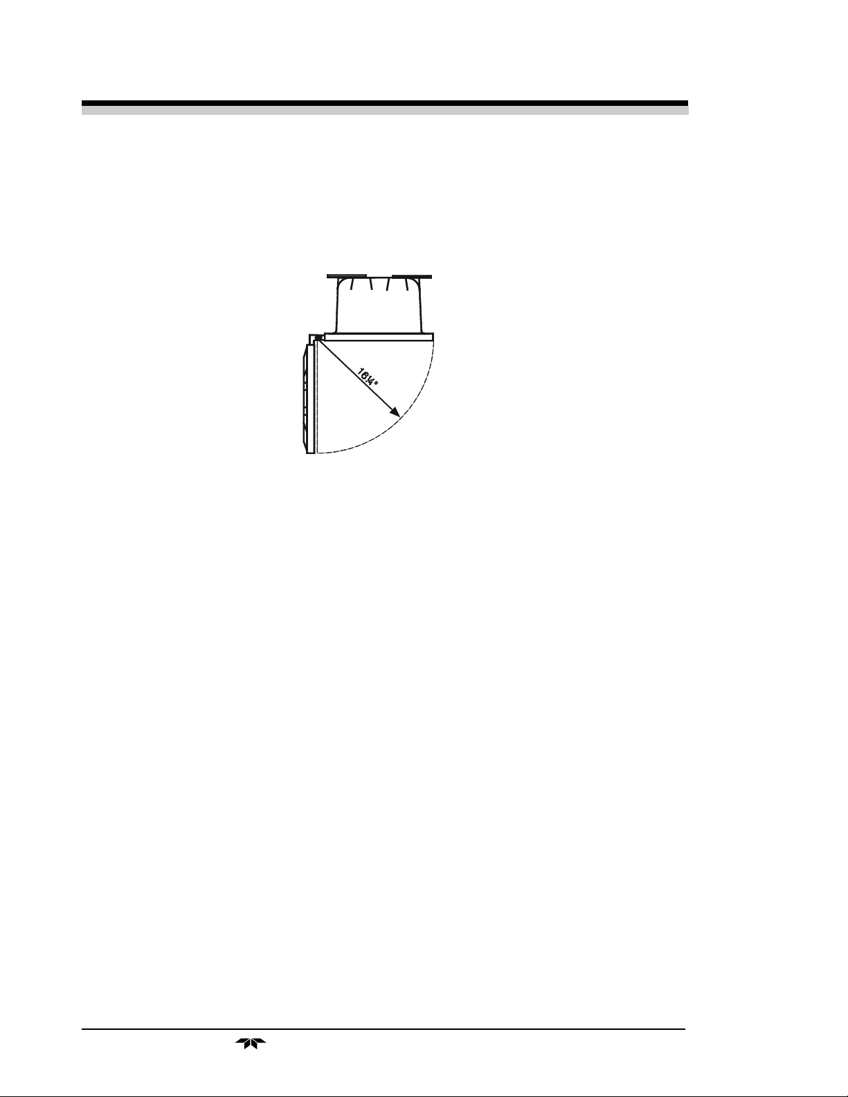
in place. Do allow enough space in front of the enclosure to swing the door open
(a 16 1/4 radius as shown on Fig. 2-1).
Figure 2-1: Required Front Door Clearance
2.2.1 User Connections
All user connections are made via cables which enter the
explosion-proof housing through ports on its side. No conduit fittings are
supplied. The installer must provide two 3/4” NPT and two 1” NPT adapters
and the appropriate sealing conduit.
2.2.2 Electrical Power Connections
The standard power requires a supply of 100-125VAC, single-phase
power. Power connections are made inside the alalyzer at the properly labeled
strip terminal. Refer to the input-output diagram for more information. The
electrical power service must include a high-quality ground wire. A highquality ground wire is a wire that has zero potential difference when measured
to the power line neutral. 220 or 240 VAC, 50/60 Hz power is optional. Check
the analyzer input-output diagram, power schematic, outline, and wiring diagrams for incoming power specifications and connecting points.
Warning: Primary power to the system should not be supplied until
all customer wiring is inspected properly by start-up personnel.
as zero gas.
2-2
2.2.3 Calibration Gases
The system may require a supply of clean, oil and particulate free air for use
Teledyne Analytical Instruments

Photometric Analyzer Installation 2
For accurate calibration, the analyzer requires a blended gas mixture,
typically 80-90% of the full scale range. For examle: a 0-1% CO analyzer,
should use a 0.8 to 0.9% CO in N2 bottled mixture. The gas blend should be a
working certified standard, analyzed by the gas supplier to at least 2% accuracy.
Do not restrict the bypass, sample or reference vents of the analyzer (and
sample system when provided). All lines must vent to a stable safe area-typically
1 ATM A +/- 0.005 pressure (0 psig +/- 0.07). Be sure to vent the analyzer exit
to atmospheric unless otherwise indicated by the system piping schematic. Refer
to the systsem outline, piping schematics for proper connections and flow paths
of the analysis system.
2.2.4 Pipe Connections
Refer to Appendix Piping Drawings for information about pipe connections. On special systems, consult the text in the manual that describes your
particular sample system in detail.
2.2.5 Sample Delivery System
The sample delivery system should be designed to operate reliably and
must be of large enough capacity to avoid flow stops. A pump is required only
if there is insufficient pressure to reliably supply the sample to the system
equipment panel. Do not complicate the delivery system by adding a pump
unless it is absolutely necessary. If a pump is required, select a type that can
handle the sample (corrosion), as well as meet the area classification and
Environmental conditions.
2.2.6 Venting the System
In gas analysis systems, the system vent manifold or bypass/sample vents
must terminate in a safe area as the sample may be poisonous, corrosive or
flammable.
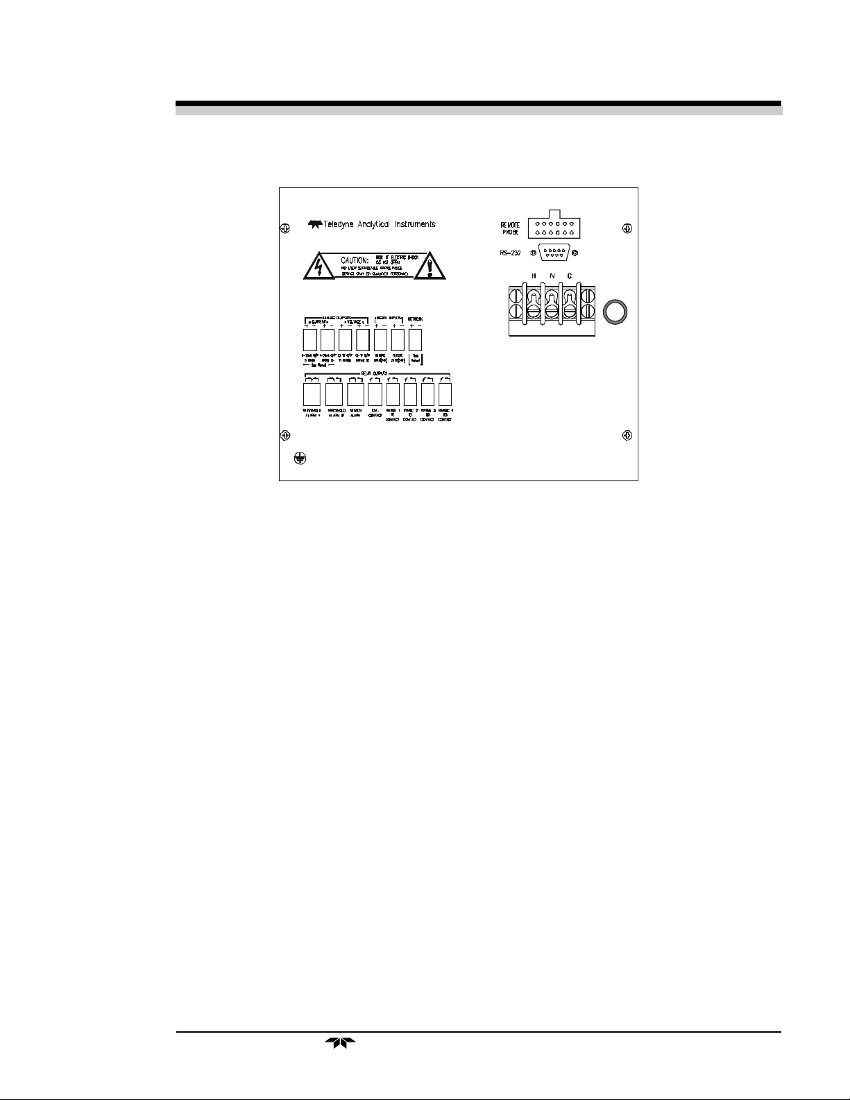
2.3 Electrical Connections
Figure 2-2 shows the Model 7120 interface panel. There are connectors
for power, digital communications, and both digital and analog concentration
output.
For safe connections, no uninsulated wiring should be able to come in
contact with fingers, tools or clothing during normal operation.
Teledyne Analytical Instruments
2-3

2 Installation Model 7120
CAUTION: Use Shielded Cables. Also, use plugs that provide
excellent EMI/RFI protection. The plug case must be
connected to the cable shield, and it must be tightly
fastened to the analyzer with its fastening screws.
Ultimately, it is the installer who ensures that the
connections provide adequate EMI/RFI shielding.
2.3.1 Primary Input Power
The power strip is located at the interface panel iside the analyzer.
DANGER: POWER IS APPLIED TO THE INSTRUMENT'S CIR-
CUITRY AS LONG AS THE INSTRUMENT IS CONNECTED TO THE POWER SOURCE. THE STANDBY
FEATURE ON THE FRONT PANEL IS FOR SWITCHING POWER ON OR OFF TO THE DISPLAYS AND
OUTPUTS ONLY.
The standard power supply requires a 110 VAC, 50-60 Hz power
source. 220 VAC, 50-60 Hz power-optional.
2.3.2 Fuse Installation
The fuse block, at the right of the power cord receptacle is 2A for
115VAC or 1A for 115VAC. Be sure to install the proper fuse as part of
installation.
2.3.3 Terminal Block Connections
Figure 2-2 shows the terminal block layout of the Equipment Interface
panel. The arrangement is shown as seen when the viewer faces the interface
panel from the front of the analyzer.
2-4
Teledyne Analytical Instruments
Photometric Analyzer Installation 2
FUSE
2A
Figure 2-2: Analog Output Connections
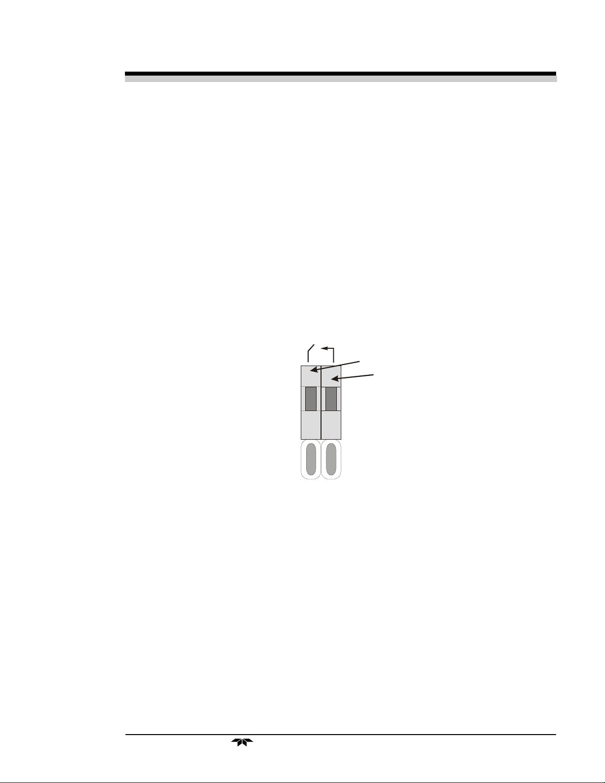
2.3.3.1 Analog Outputs
There are four DC output signal pins—two pins per output. For polar-
ity, see Figure 2-3. The outputs are:
0–1 V dc % of Range: Voltage rises linearly with increasing concentration,
from 0 V at 0 concentration to 1 V at full scale.
(Full scale = 100% of programmable range.)
0–1 V dc Range ID: 0.25 V = Range 1, 0.5 V = Range 2, 0.75 V =
Range 3, 1 V = Cal Range.
4–20 mA dc % Range: Current rises linearly with concentration, from 4
mA at 0 concentration to 20 mA at full scale. (Full
scale = 100% of programmable range.)
4–20 mA dc Range ID: 8 mA = Range 1, 12 mA = Range 2, 16 mA =
Range 3, 20 mA = Range 4.
Figure 2-3: Analog Output Connections
Teledyne Analytical Instruments
2-5
2 Installation Model 7120
Current
Optional
Floating
CURRENT
++++
VOLTAGE
Negative
ground
Insert wire
here.
Press here to
insert wire.
Release to hold.
4-20mA O/P
% RANGE
4-20mA O/P
RANGE ID
0-1 V O/P
% RANGE
0-1 V O/P
RANGE ID
The analog output signal has a voltage which depends on gas concentration relative to the full scale of the range. To relate the signal output to the
actual concentration, it is necessary to know what range the instrument is
currently on, especially when the analyzer is in the autoranging mode.
The signal output for concentration is linear over the currently selected
analysis range. For example, if the analyzer is set on a range that was defined
Examples:
The analog output signal has a voltage which depends on gas concentration relative to the full scale of the range. To relate the signal output to the
actual concentration, it is necessary to know what range the instrument is
currently on, especially when the analyzer is in the autoranging mode.
Examples:
The signal output for concentration is linear over the currently selected
analysis range. For example, if the analyzer is set on a range that was defined
as 0–10 % hydrogen, then the output would be as shown in Table 2-3.
Table 2-3: Analog Concentration Output—Example
Percent Voltage Signal Current Signal
CO Output (V dc) Output (mA dc)
0 0.0 4.0
1 0.1 5.6
2-6
Teledyne Analytical Instruments

Photometric Analyzer Installation 2
2 0.2 7.2
3 0.3 8.8
4 0.4 10.4
5 0.5 12.0
6 0.6 13.6
7 0.7 15.2
8 0.8 16.8
9 0.9 18.4
10 1.0 20.0
To provide an indication of the range, the Range ID analog outputs are
used. They generate a steady preset voltage (or current when using the
current outputs) to represent a particular range. Table 2-4 gives the range ID
output for each analysis range.
Table 2-4: Analog Range ID Output—Example
Range Voltage (V) Current (mA) Application
Range 1 0.25 8 90-100% CO/N
Range 2 0.50 12 95-100% CO/N
Range 3 0.75 16 0-100% CO/N
Range 4 (Cal) 1.00 20 98-100% CO2/N
2
2
2
2
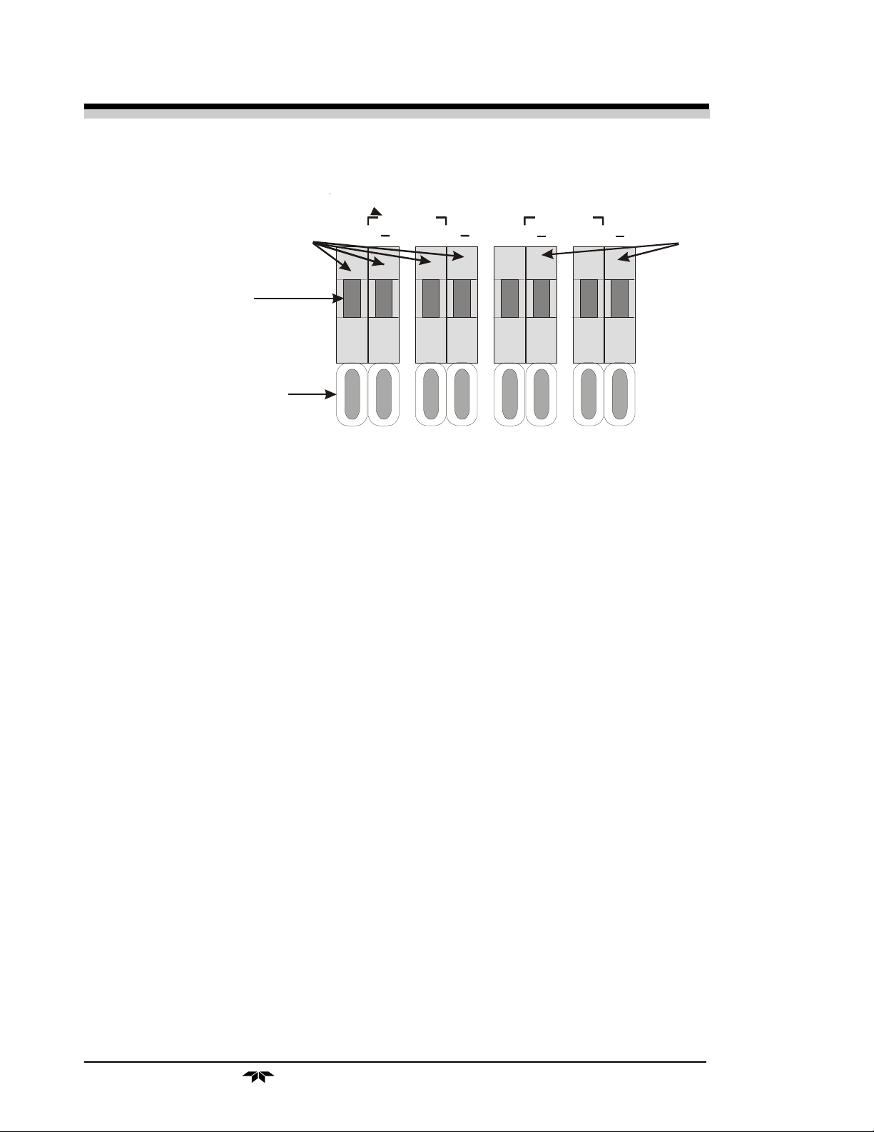
2.3.3.2 Alarm Relays
The nine alarm-circuit connector pins connect to the internal alarm relay
contacts. Each set of three pins provides one set of Form C relay contacts.
Each relay has both normally open and normally closed contact connections.
The contact connections are shown in Figure 2-4. They are capable of
switching up to 3 amperes at 250 V ac into a resistive load. The connectors
are:
Threshold Alarm 1: • Can be configured as high (actuates when concen-
tration is above threshold), or low (actuates when
concentration is below threshold).
• Can be configured as failsafe or nonfailsafe.
• Can be configured as latching or nonlatching.
• Can be configured out (defeated).
Threshold Alarm 2: • Can be configured as high (actuates when concen-
tration is above threshold), or low (actuates when
Teledyne Analytical Instruments
2-7

2 Installation Model 7120
concentration is below threshold).
• Can be configured as failsafe or nonfailsafe.
• Can be configured as latching or nonlatching.
• Can be configured out (defeated).
System Alarm: Actuates when DC power supplied to circuits is
unacceptable in one or more parameters. Permanently
configured as failsafe and latching. Cannot be defeated. Actuates if self test fails.
(Reset by pressing button to remove power. Then
press again and any other button EXCEPT
System to resume.
Further detail can be found in chapter 4, section 4-5.concentration is
below threshold).
• Can be configured as failsafe or nonfailsafe.
• Can be configured as latching or nonlatching.
• Can be configured out (defeated).
System Alarm: Actuates when DC power supplied to circuits is
unacceptable in one or more parameters. Permanently
configured as failsafe and latching. Cannot be defeated. Actuates if self test fails.
(Reset by pressing button to remove power. Then
press again and any other button EXCEPT
System to resume.
Further detail can be found in chapter 4, section 4-5.
2-8
Teledyne Analytical Instruments
Photometric Analyzer Installation 2
Figure 2-4: Alarm Relay Contact Pins
Normally open
Normally closed
Moving contact
Insert wire
here.
Press here to
insert wire.
Release to hold.
THRESHOLD
ALARM 1
Remote Calibration Protocol: To properly time the Digital Remote
Cal Inputs to the Model 7120 Analyzer, the customer's controller must
monitor the Cal Relay Contact.
When the contact is OPEN, the analyzer is analyzing, the Remote Cal
Inputs are being polled, and a zero or span command can be sent.
When the contact is CLOSED, the analyzer is already calibrating. It
will ignore your request to calibrate, and it will not remember that request.
Once a zero or span command is sent, and acknowledged (contact
closes), release it. If the command is continued until after the zero or span is
complete, the calibration will repeat and the Cal Relay Contact (CRC) will
close again.
For example:
1) Test the CRC. When the CRC is open, Send a zero command
until the CRC closes (The CRC will close quickly.)
2) When the CRC closes, remove the zero command.
3) When CRC opens again, send a span command until the CRC
closes. (The CRC will close quickly.)
4) When the CRC closes, remove the span command.
Teledyne Analytical Instruments
2-9

2 Installation Model 7120
When CRC opens again, zero and span are done, and the sample is
being analyzed.
Note: The Remote Probe connector provides signals to operate the
zero and span gas valves synchronously. However, if you
have the –C Internal valve option, which includes zero and
span gas inputs, the 7120 automatically regulates the zero,
span and sample gas flow.
2.3.3.4 Range ID Relays
Four dedicated Range ID relay contacts. For any single application they
are assigned to relays in ascending order. For example: if all ranges have the
same application, then the lowest range is assigned to the Range 1 ID relay,
and the highest range is assigned to the Range 3 ID relay. Range 4 is the Cal
Range ID relay. Figure 2-6 lists the pin connections.
Table 2-6: Remote Calibration Connections
Pin Function
9 + Remote Zero
11 – Remote Zero
10 + Remote Span
12 – Remote Span
40 Cal Contact
41 Cal Contact
Remote Calibration Protocol: To properly time the Digital Remote
Cal Inputs to the Model 7120 Analyzer, the customer's controller must
monitor the Cal Relay Contact.
When the contact is OPEN, the analyzer is analyzing, the Remote Cal
Inputs are being polled, and a zero or span command can be sent.
When the contact is CLOSED, the analyzer is already calibrating. It
will ignore your request to calibrate, and it will not remember that request.
Once a zero or span command is sent, and acknowledged (contact
closes), release it. If the command is continued until after the zero or span is
complete, the calibration will repeat and the Cal Relay Contact (CRC) will
close again.
2-10
For example:
1) Test the CRC. When the CRC is open, Send a zero command
until the CRC closes (The CRC will close quickly.)
Teledyne Analytical Instruments
Photometric Analyzer Installation 2
2) When the CRC closes, remove the zero command.
3) When CRC opens again, send a span command until the CRC
closes. (The CRC will close quickly.)
4) When the CRC closes, remove the span command.
When CRC opens again, zero and span are done, and the sample is
being analyzed.
Note: The Remote Probe connector provides signals to operate the
zero and span gas valves synchronously. However, if you
have the –C Internal valve option, which includes zero and
span gas inputs, the 7120 automatically regulates the zero,
span and sample gas flow.
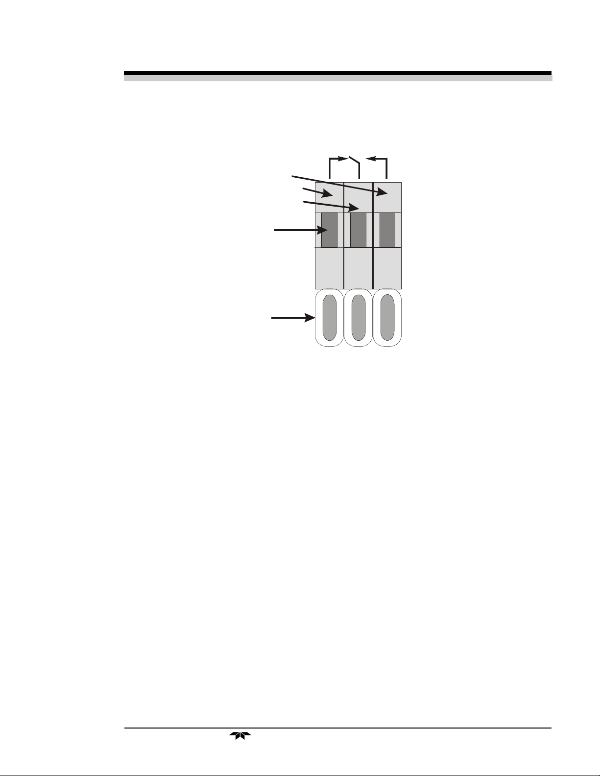
2.3.3.4 Range ID Relays
Moving contact
Normally
open
RANGE 1
ID
CONTACT
Four dedicated Range ID relay contacts. For any single application they
are assigned to relays in ascending order. For example: if all ranges have the
same application, then the lowest range is assigned to the Range 1 ID relay,
and the highest range is assigned to the Range 3 ID relay. Range 4 is the Cal
Range ID relay. Table 2-7 lists the pin connections.
Table 2-7: Range ID Relay Connections
Pin Function
21 Range 1 ID Contact
38 Range 1 ID Contact
22 Range 2 ID Contact
Teledyne Analytical Instruments
2-11
2 Installation Model 7120
39 Range 2 ID Contact
19 Range 3 ID Contact
18 Range 3 ID Contact
34 Range 4 ID Contact
35 Range 4 ID Contact
2.3.3.5 Network I/O
A serial digital input/output for local network protocol. At this printing,
this port is not yet functional. It is to be used in future options to the instrument.
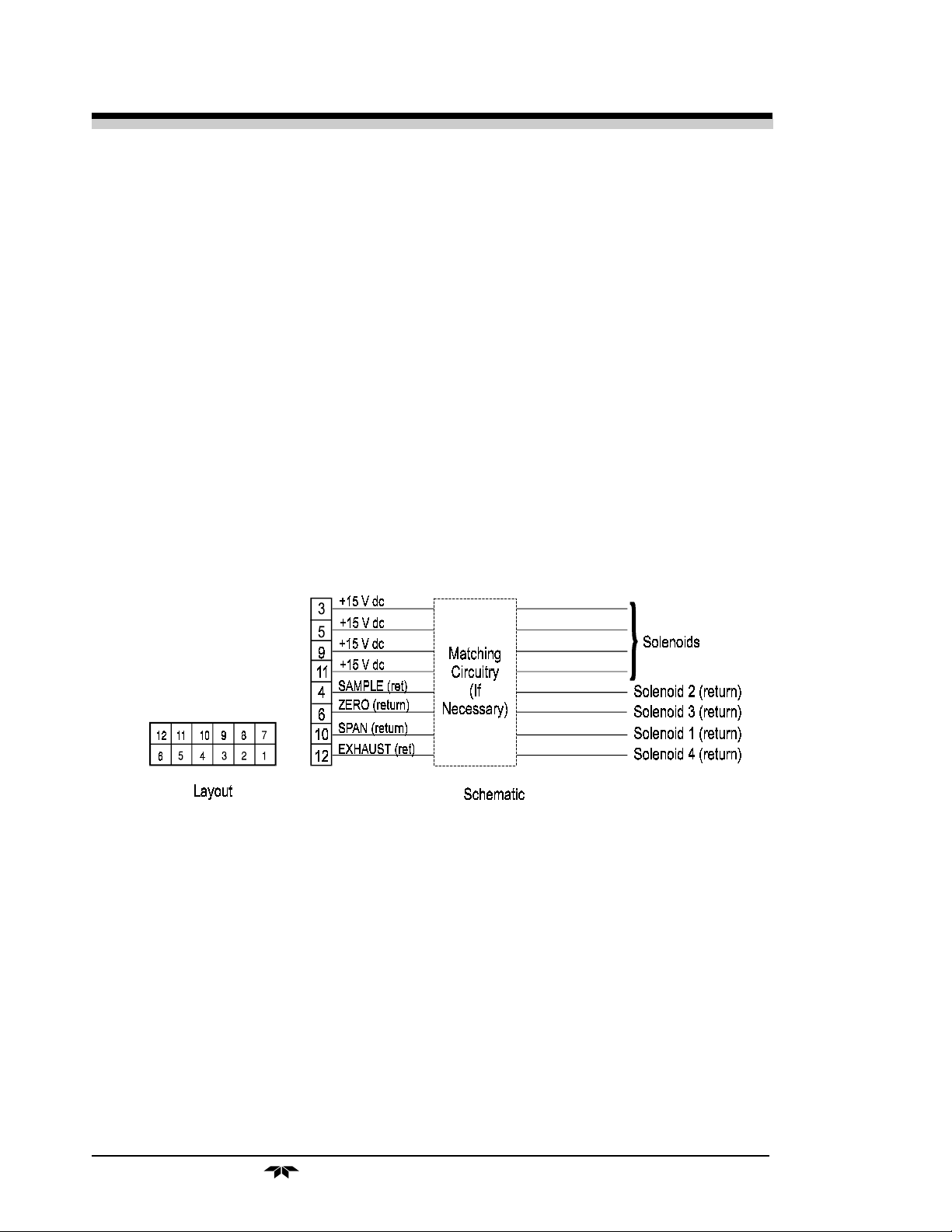
2.3.3.6 Remote Valve Connector
The 7120 is a single-chassis instrument, which has no Remote Probe
Unit. Instead, the Remote Valve connector is used as another method for
controlling external sample/zero/span gas valves. See Figure 2-7.
Figure 2-7: Remote Probe Connector Pinouts
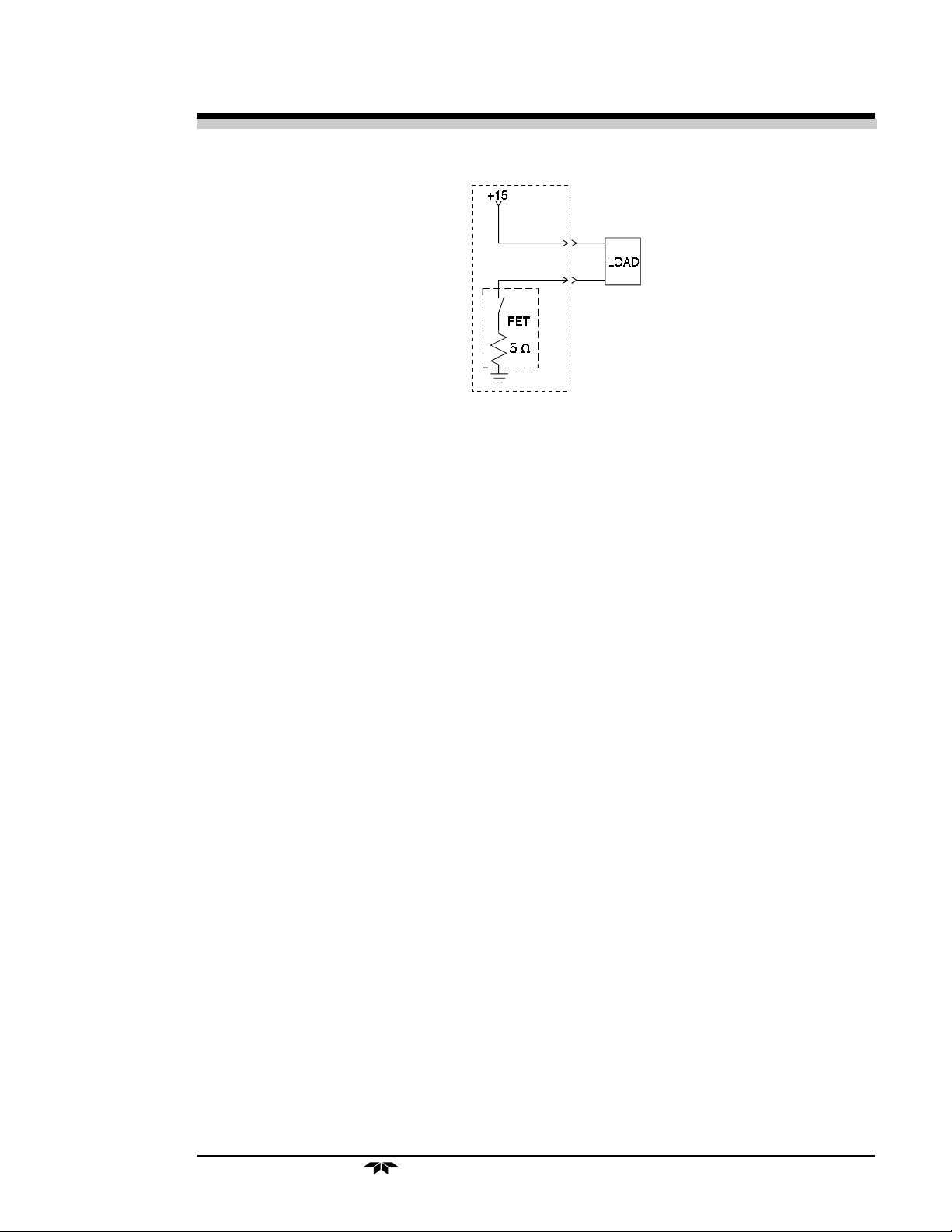
The voltage from these outputs is nominally 0 V for the OFF and
15 V dc for the ON conditions. The maximum combined current that can be
pulled from these output lines is 100 mA. (If two lines are ON at the same
time, each must be limited to 50 mA, etc.) If more current and/or a different
voltage is required, use a relay, power amplifier, or other matching circuitry
to provide the actual driving current.
In addition, each individual line has a series FET with a nominal ON
resistance of 5 ohms (9 ohms worst case). This could limit the obtainable
voltage, depending on the load impedance applied. See Figure 2-8.
2-12
Teledyne Analytical Instruments
Photometric Analyzer Installation 2
Figure 2-8: FET Series Resistance
2.3.4 RS-232 Port
The digital signal output is a standard RS-232 serial communications
port used to connect the analyzer to a computer, terminal, or other digital
device. It requires a standard 9-pin D connector.
Output: The data output is status information, in digital form, updated
every two seconds. Status is reported in the following order:
• The concentration in ppm or percent
• The range in use (00 = Range 1, 01 = Range 2, 10 = Range 3, 11
= Range 4)
• The span of the range (0-100 %, etc)
• Which alarms—if any—are disabled (AL–x DISABLED)
• Which alarms—if any—are tripped (AL–x ON).
Each status output is followed by a carriage return and line feed.
Input: The input functions using RS-232 that have been implemented
to date are described in Table 2-3.
Table 2-8: Commands via RS-232 Input
Command Description
as<enter> Immediately starts an autospan.
az<enter> Immediately starts an autozero.
rp<enter> Allows reprogramming of two System functions:
APPLICATION (gas use) and ALGORITHM (linearization).
Teledyne Analytical Instruments
2-13

2 Installation Model 7120
st<enter> Toggling input. Stops/Starts any status message output from
the RS-232, until st<enter> is sent again.
Implementation: The RS-232 protocol allows some flexibility in its
implementation. Table 2-9 lists certain RS-232 values that are required by
the Model 7120 implementation.
Table 2-9: Required RS-232 Options
Parameter Setting
Baud 2400
Byte 8 bits
Parity none
Stop Bits 1
Message Interval 2 seconds
2.4 Gas Requirements
Instrument Air is required for zeroing of the Infrared Analyzer. It must
be free of oil, particulates and water vapor (that will not condensate,
unfiltered plant air is not recommended). A supply pressure of 10100psig with a typical flow rate of 2 scfh (1 lpm) is needed. Bottled gas is
recommended (air or Nitrogen) if high quality air is not available.
For accurate calibration, the analyzer requires blended gas mixtures
certified to +/- 2% accuracy.
2.5 Testing the System
Before plugging the instrument into the power source:
• Check the integrity and accuracy of the fluid connections. Make
sure there are no leaks.
• Check the integrity and accuracy of the electrical connections.
Make sure there are no exposed conductors
• Check that sample pressure is controlled accuracately and is
maintained between 0 to 10 psig, according to the requirements
of your process.
operations:
2-14
NOTE: Special designed systems may require checks under vacuum
or high pressure (consult manual addendum).
Power up the system, and test it by performing the following
Teledyne Analytical Instruments

Photometric Analyzer Installation 2
1. Repeat the Self-Diagnostic Test, section 5.2
2.6 Calibration
2.6.1 Calibration Fluids
Zero and span fluids must be made by the chemistry lab or certified zero
and span gas bought from a gas supplier. The zero fluid must be the major
component of the sample, free from the component of interest. In purity
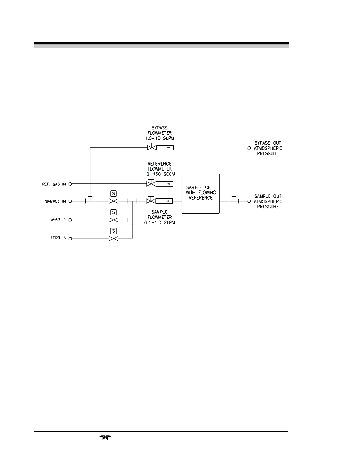
applications, the accuracy is only as good as the purity of the zero gas used to
reference to. The 7120 has a continuous flowing optical reference gas path that
the sample is compared to, so it must be very pure, i.e, CO2 purity of 99.995%.
Typically this reference flow is about 20 ccm.
Note: In Non-purity applications, the reference cell may be sealed
with clean air (consult factory).
The span fluid must be the major component of the sample mixed with
a small amount of the component of interest. The concentration must be 80 to
95% of the full scale range or the widest range of the instrument (if the instrument
provides more than one range). (i.e, for a 98-100% CO2 range purity, use span
of 98.40% N2 in 99.995% pure CO2).
2.6.2 Calibration
Refer to Section 4.4 of the manual to determine how to manipulate the
mode setting. The recommended calibration method is as follows:
1. Calibration with zero and span fluids. (Note: Zero gas may be 100% gas
in purity applications).
Method:
1. Introduce zero fluid and set zero as referred in section 4.4.1
NOTE: When calibrating from 0% to an upper concentration gas, obtain
a zero gas (minus the analyte) that typically is as pure as the minimum resolution
needed to control to. This usually meets or exceeds the minimum full scale
accuracy of the measurement.
2. Introduce a span fluid and set the concentration of the span fluid.
Refer to the span procedure in section 4.4.2. (Note: The span gas should
typically be an 80% of full scale range gas similar to the 100% zero gas
background; i.e., 100% CO2 zero gas and a span gas of 98.4% CO2 in N2 for
a 98-100%CO2 purity application.
Teledyne Analytical Instruments
2-15

Photometric Analyzer Start-up and Operation
3.0 Start-up and Operation
3.1 Preliminary
Before applying power to the system, TAI suggests that the electrical
wiring installation be checked against the system input-output diagram.
Proper attention to this preliminary check will prevent severe damage caused
by wiring errors.
Also, verify that all connections to the system have been made
correctly. Refer to the system outline diagram for proper connections.
3.2 NDIR Analyzer Startup
Power up the unit by depressing the rear panel switch. From a first
time power-on cold start attempt, allow (1) one hour warm-up to proceed.
Observe that the Digital display will go through a diagnostic routine before
the readings revert to a continuous concentration readout.
3.2.1 Initial Set-up and Zeroing
Assure the sample will enter from the zero inlet gas position. Open the
zero gas tank and set the pressure regulator to 20 psig. Set the zero gas flow
to 2 SCFH (1 lpm). Set the sample flow to 2 SCFH (1 lpm). When
applicable, assume the flowing reference cell gas is flowing between 20-50
ccm.
Initialize a zero operation through the system menu. Refer to Section 4
for Electronics /Control Unit Modes and Functioning to navigate the zero
menu.
After the zero cycle is over, the instrument is automatically brought in
the sampling cycle. An inaccurate reading of the concentration of the gas of
interest will be obtained. The instrument is not yet calibrated. Permit the
instrument to operate in this mode for at least one hour to stabilize if not
already done so upon initial power up.
NOTE: The following options could be included in your system:
In case the instrument is part of a multi instrument system, where all
instruments are connected to the same sample system and under control of a
single timer, all instruments of the system will go through the zero and
sample cycle simultaneously. The Control Unit of the instrument which
Teledyne Analytical Instruments
3-1

3 Start-up and Theory of Operation Model 7120
houses the timer and operates the sampling system is called the master. The
other Control Units of the other instruments are called slaves.
Each of the other instruments may be monitoring the concentration of
several different gases of interest in the sample, for example CO, CO2 and/or
Combustibles as CH4 in flue gas.
3.2.2 Operational Calibration
After the instrument has stabilized, let zero gas flow through the
analyzer
Perform a zero of the analyzer.
Perform a span of the analyzer.
Open the span gas tank and set the pressure regulator to 20 psig.
Switch the mode switch to sample. Refer to Section 4 again.
Induce an automatic zero cycle as described in Section 4 also.
After the zero cycle, the analyzer reverts to the sample cycle. The
sample reading is now accurate and the analyzer is placed in continuous
operation. See Sections 4.6-4.8.
NOTE: In case slave analyzers are involved, calibrate them
simultaneously with the master analyzer.
After the instrument is calibrated, when no Auto-Cal option was
selected, shut off the main valve on the span gas tank. This tank is not used
during automatic sampling. Leave the zero tank open.
3.3 Theory of operation
3.3.1 General
The non-dispersive infrared (NDIR) analyzer is one of the major components
of the system. It employs the basic principles of spectroscopic analysis to
measure a specific concentration of one gas in a multicomponent gas system.
The concentration of a gas is determined by exposing a chamber filled with a
gas mixture to infrared radiant energy and measuring how much of the
specific (non-dispersive) infrared wavelength is absorbed by the gas being
measured.
As an example, the NDIR analyzer is used most in flue gas applications
where the amount of carbon monoxide in a flue gas mixture is measured.
The specific infrared wavelength at which the carbon monoxide molecule
absorbs infrared energy is at 4.65 microns. The more carbon monoxide
present in the measurement cell, the more energy its molecules absorb.
The NDIR analyzer needs four basic components to measure the spectral
3-2
Teledyne Analytical Instruments
 Loading...