

Page 1

OPERATOR’S MANUAL
MODEL 703E
PHOTOMETRIC O
© TELEDYNE INSTRUMENTS
ADVANCED POLLUTION INSTRUMENTATION DIVISION
(TAPI)
9480 CARROLL PARK DRIVE
SAN DIEGO, CALIFORNIA 92121-5201
USA
Toll-free Phone: 800-324-5190
Phone: 858-657-9800
Fax: 858-657-9816
Email: api-sales@teledyne.com
Website: http://www.teledyne-api.com/
CALIBRATOR
3
05743 Rev. C
Copyright 2007 DCN 5521
Teledyne Advanced Pollution Instrumentation 29 July 2009
Page 2

THIS PAGE IS INTENTIONALLY LEFT BLANK
Page 3

PRINTED DOCUMENTS ARE UNCONTROLLED.
We recommend that this document be read in its entirety before any attempt is
made to operate the instrument.
DOCUMENTS
Document P/N Revision DCN Nomenclature Dated
05743 B 5359 M703, Manual, Instruction - Title 03/20/09
05744 B 5359 M703, Manual, Instruction - Text 03/20/09
05745 C 5359 M703, Appendix A, Menu Tree 03/20/09
05746 B 5359 M703, Appendix B, Spare Parts 03/20/09
05747 B 5359 M703, Appendix C, Repair Form 03/20/09
05748 B 5359 M703, Appendix D, Schematics 03/20/09
05834 F 5359 List, Spare Parts, M703 03/20/09
05863 B 5359
05834 J 5480 List, Spare Parts, M703 07/15/09
05863 D 5480
List, Recommended Spares Stocking Levels,
M703
List, Recommended Spares Stocking Levels,
M703
03/20/09
07/15/09
Page 4

THIS PAGE IS INTENTIONALLY LEFT BLANK
Page 5
TELEDYNE API
M703E Calibrator Operator’s Manual Safety Messages
SAFETY MESSAGES
Your safety and the safety of others are very important. We have provided many important safety messages in
this manual. Please read these messages carefully.
A safety message alerts you to potential hazards that could hurt you or others. Each safety message is
associated with a safety alert symbol. These symbols are found in the manual and inside the M703E
Photometric O3 Calibrator. The definition of these symbols is described below:
GENERAL SAFETY HAZARD: Refer to the instructions for details on the specific
hazard.
CAUTION: Hot Surface Warning.
CAUTION: Electrical Shock Hazard.
TECHNICIAN SYMBOL: All operations marked with this symbol are to be
performed by qualified maintenance personnel only.
CAUTION
The M703E Photometric O3 Calibrator should only be used for the purpose and in the manner described
in this manual. If you use the M703E in a manner other than that for which it was intended,
unpredictable behavior could ensue with possible hazardous consequences.
NOTE
Technical Assistance regarding the use and maintenance of the
M703E or any other Teledyne Instruments product
can be obtained by:
Contacting Teledyne Instruments’ Customer Service Department at 800-324-5190
or
Via the internet at http://www.teledyne-api.com/forms
05744 Rev B i
Page 6

TELEDYNE API
Safety Messages M703E Dynamic Operator’s Manual
USER NOTES:
ii 05744 Rev B
Page 7

TELEDYNE API
M703E Calibrator Operator’s Manual Table of Contents
TABLE OF CONTENTS
GENERAL INFORMATION....................................................................................................... 1
1. INTRODUCTION .................................................................................................................. 3
1.1. M703E calibrator Overview............................................................................................................................3
1.2. Using This Manual .........................................................................................................................................3
2. SPECIFICATIONS, APPROVALS AND WARRANTY ......................................................... 5
2.1. Specifications .................................................................................................................................................5
2.2. CE Mark Compliance .....................................................................................................................................6
2.3. Warranty.........................................................................................................................................................7
3. GETTING STARTED ............................................................................................................ 9
3.1. Unpacking and Initial Setup ...........................................................................................................................9
3.1.1. Model 703E calibrator............................................................................................................................10
3.2. Electrical Connections .................................................................................................................................13
3.2.1. Power Connection..................................................................................................................................13
3.2.2. Analog output TEST CHANNEL Connections .......................................................................................13
3.2.3. Connecting the Status Outputs..............................................................................................................14
3.2.4. Connecting the Control Inputs ...............................................................................................................15
3.2.5. Connecting the Control Outputs ............................................................................................................17
3.2.6. Connecting the Serial Ports ...................................................................................................................18
3.2.7. Connecting to a LAN or the Internet ......................................................................................................18
3.2.8. Connecting to a Multidrop Network........................................................................................................18
3.3. Pnenumatic Connections .............................................................................................................................19
3.3.1. Dry Air In ................................................................................................................................................19
3.3.2. Zero Air In ..............................................................................................................................................19
3.3.3. Output Manifold......................................................................................................................................20
3.3.4. Exhaust ..................................................................................................................................................20
3.3.5. Measuring An External Ozone Source ..................................................................................................20
3.4. Initial Operation............................................................................................................................................21
3.4.1. START-UP .............................................................................................................................................21
3.4.2. Warm Up................................................................................................................................................22
3.4.3. Warning Messages ................................................................................................................................22
3.4.4. Functional Check ...................................................................................................................................24
3.4.5. Operating Modes for the O
3.4.5.1. CNST (CONSTANT).......................................................................................................................25
3.4.5.2. REF (REFERENCE).......................................................................................................................25
3.4.5.3. BNCH (BENCH) .............................................................................................................................25
3.4.6. Setting the O3 Generator Mode.............................................................................................................25
3.4.7. Setting the M703E’s output Flow Rate ..................................................................................................26
Generator..................................................................................................25
3
4. FREQUENTLY ASKED QUESTIONS AND GLOSSARY .................................................. 27
4.1. FAQ’s ...........................................................................................................................................................27
4.2. Glossary .......................................................................................................................................................27
5. OPTIONAL HARDWARE AND SOFTWARE ..................................................................... 29
5.1. Carrying Strap Handle (OPT 29)..................................................................................................................29
5.2. Communication Options...............................................................................................................................30
5.2.1. RS232 Modem Cables (OPTs 60 and 60A) ..........................................................................................30
5.2.2. ETHERNET Cable (OPT 60B)...............................................................................................................30
5.2.3. RS-232 Multidrop (OPT 62) ...................................................................................................................30
5.2.4. Ethernet (OPT 63)..................................................................................................................................31
5.2.5. Ethernet + Multidrop (OPT 64)...............................................................................................................32
5.3. Additional Manual (OPT 70).........................................................................................................................32
5.4. Extended Warranty (OPT 92) ......................................................................................................................32
5.5. NIST Traceable, Primary Standard CERTIFICATION.................................................................................32
OPERATING INSTRUCTIONS................................................................................................ 33
6. OPERATING THE M703E CALIBRATOR ......................................................................... 35
6.1. Test Functions..............................................................................................................................................36
05744 Rev B iii
Page 8

TELEDYNE API
Table of Contents M703E Calibrator Operator’s Manual
6.2. Overview of Operating modes .....................................................................................................................37
6.3. STANDBY Mode ..........................................................................................................................................38
6.4. General Information about the GENERATE mode ......................................................................................39
6.4.1. GENERATE AUTO: Basic Generation of Calibration Gas................................................................39
6.5. AUTOMATIC CALIBRATION SEQUENCES ...............................................................................................40
6.5.1. SETUP SEQ: Programming Calibration Sequences.........................................................................40
6.5.1.1. Activating a Sequence from the M703E Front Panel .....................................................................41
6.5.1.2. Naming a Sequence.......................................................................................................................42
6.5.1.3. Setting the Repeat Count for a Sequence .....................................................................................43
6.5.1.4. Using the M703E’s Internal Clock to Trigger Sequences...............................................................44
6.5.1.5. Setting Up Control Inputs for a Sequence......................................................................................47
6.5.1.6. Setting Up Control Outputs for a Sequence...................................................................................48
6.5.1.7. Setting the PROGRESS Reporting Mode for the Sequences........................................................49
6.5.2. Adding Sequence Steps ........................................................................................................................50
6.5.2.1. The Generate Step.........................................................................................................................51
6.5.2.2. The STANDBY Step.......................................................................................................................52
6.5.2.3. The DURATION Step .....................................................................................................................52
6.5.2.4. The EXECSEQ Step.......................................................................................................................53
6.5.2.5. The CC OUTPUT Step...................................................................................................................54
6.5.2.6. Deleting or Editing an Individual Step in a Sequence ....................................................................55
6.5.3. Deleting a Sequence .............................................................................................................................56
6.6. SETUP CFG ............................................................................................................................................57
6.7. SETUP CLK.............................................................................................................................................58
6.7.1. Setting the internal Clock’s Time and Day.............................................................................................58
6.7.2. Adjusting the internal Clock’s speed......................................................................................................59
6.8. SETUP PASS ..........................................................................................................................................60
6.9. SETUP DIAG TEST CHAN OUTPUT: Using the TEST Channel Analog Output...............................62
6.9.1. Configuring the TEST CHANNEL Analog Output..................................................................................62
6.9.1.1. The Analog I/O Configuration Submenu. .......................................................................................62
6.9.1.2. Selecting a Test Channel Function to Output ................................................................................64
6.9.1.3. TEST CHANNEL VOLTAGE RANGE Configuration......................................................................66
6.9.1.4. Turning the TEST CHANNEL Over-Range Feature ON/OFF........................................................67
6.9.1.5. Adding a Recorder Offset to the TEST CHANNEL ........................................................................68
6.9.2. TEST CHANNEL CALIBRATION ..........................................................................................................69
6.9.2.1. Enabling or disabling the TEST CHANNEL Auto-Cal Feature.......................................................69
6.9.2.2. Automatic TEST CHANNEL Calibration.........................................................................................70
6.9.2.3. Manual Calibration of the TEST CHANNEL configured for Voltage Ranges.................................72
6.9.3. AIN Calibration.......................................................................................................................................74
6.10. SETUP MORE VARS: Internal Variables (VARS)............................................................................75
6.11. Operating the M703E Calibrator as an O3 Photometer .............................................................................77
6.11.1. Set up for Operating the M703E as an O
Photometer .......................................................................77
3
6.12. SETUP LVL: Setting up and using LEADS (Dasibi) Operating Levels .................................................79
6.12.1. General Information about LEADS LEVELS .......................................................................................79
6.12.2. Dot commands.....................................................................................................................................79
6.12.3. Levels...................................................................................................................................................80
6.12.4. Activating an existing LEVEL...............................................................................................................80
6.12.5. Programming New LEVELS ................................................................................................................81
6.12.5.1. Creating a GENERATE LEVEL....................................................................................................82
6.12.5.2. Creating a MANUAL LEVEL.........................................................................................................83
6.12.5.3. Editing or Deleting a LEVEL.........................................................................................................84
6.12.6. Configuring LEVEL Status Blocks .......................................................................................................86
7. OPERATING THE M703E OVER THE SERIAL I/O PORTS.............................................. 87
7.1. Using the Analyser’s Communication Ports.................................................................................................87
7.1.1. RS-232 DTE and DCE Communication.................................................................................................87
7.1.2. COMM Port Default Settings and Connector Pin Assignments.............................................................88
7.1.3. COMM Port Baud Rate..........................................................................................................................90
7.1.4. COMM Port Communication Modes ......................................................................................................91
7.1.5. COMM Port Testing ...............................................................................................................................93
iv 05744 Rev B
Page 9

TELEDYNE API
M703E Calibrator Operator’s Manual Table of Contents
7.1.6. Machine ID.............................................................................................................................................94
7.1.7. Terminal Operating Modes ....................................................................................................................95
7.1.7.1. Help Commands in Terminal Mode................................................................................................95
7.1.7.2. Command Syntax...........................................................................................................................96
7.1.7.3. Data Types .....................................................................................................................................96
7.1.7.4. Status Reporting.............................................................................................................................97
7.1.7.5. COM Port Password Security.........................................................................................................98
7.2. Remote Access by Modem ..........................................................................................................................99
7.3. Multidrop RS-232 Set Up .......................................................................................................................... 101
7.4. RS-485 Configuration of COM2................................................................................................................ 103
7.5. Remote Access via the Ethernet............................................................................................................... 105
7.5.1. Ethernet Card COM2 Communication Modes and Baud Rate........................................................... 105
7.5.2. Configuring the Ethernet Interface Option using DHCP ..................................................................... 105
7.5.2.1. Manually Configuring the Network IP Addresses........................................................................ 108
7.5.3. Changing the Calibrator’s HOSTNAME.............................................................................................. 110
7.6. APICOM Remote Control Program........................................................................................................... 111
8. M703E CALIBRATION AND VERIFICATION.................................................................. 113
8.1. Verifying and Calibrating the M703E’s O3 Photometer............................................................................. 113
8.1.1. Setup for VERIFYING AND calibrating the O
Photometer................................................................ 113
3
8.1.1.1. Calibration Manifold Exhaust/Vent Line ...................................................................................... 114
8.1.2. Verifying O
8.1.3. Calibrating the O
Photometer Performance ............................................................................................... 115
3
Photometer............................................................................................................ 116
3
8.1.3.1. Photometer Zero Calibration ....................................................................................................... 116
8.1.3.2. Photometer Span Calibration ...................................................................................................... 117
8.1.4. O
Photometer Dark Calibration ......................................................................................................... 118
3
8.2. Calibrating the O3 Generator .................................................................................................................... 119
8.2.1. O3 Generator Calibration table........................................................................................................... 119
8.2.2. Viewing O
8.2.3. Adding or Editing O
8.2.4. Deleting O
8.2.5. Turning O
8.2.6. Performing an Automatic Calibration of the O
Generator Calibration Points............................................................................................ 120
3
Generator Calibration Points............................................................................. 121
3
Generator Calibration Points ........................................................................................... 122
3
Generator Calibration Points ON / OFF ........................................................................... 123
3
Generator ................................................................. 124
3
8.3. M703E Gas Pressure Sensor Calibration................................................................................................. 125
8.3.1.1. Gas Pressure Sensor Calibration Set Up.................................................................................... 125
8.3.2. Calibrating the Regulator and Photometer Pressure Sensors ........................................................... 127
8.4. M703E Gas Flow Calibration .................................................................................................................... 128
8.4.1. Calibrating the Photometer’s Sample Gas Flow................................................................................. 129
8.4.2. Calibrating the OuTput Gas Flow ....................................................................................................... 130
8.4.2.1. Output Gas Flow Set Up ............................................................................................................. 130
8.4.2.2. Performing an Output Gas Flow Calibration ............................................................................... 131
TECHNICAL INFORMATION................................................................................................ 133
9. THEORY OF OPERATION............................................................................................... 135
9.1. Pneumatic Operation ................................................................................................................................ 135
9.1.1. Gas Flow Control ................................................................................................................................ 135
9.1.1.1. Flow Control Assemblies............................................................................................................. 135
9.1.1.2. Photometer Critical Flow Orifice.................................................................................................. 135
9.1.2. Internal Gas Pressure Sensors........................................................................................................... 136
9.2. Electronic Operation ................................................................................................................................. 137
9.2.1. Overview ............................................................................................................................................. 137
9.2.2. CPU .................................................................................................................................................... 138
9.2.2.1. Disk On Chip ............................................................................................................................... 139
9.2.2.2. Flash Chip ................................................................................................................................... 139
9.2.3. Relay PCA .......................................................................................................................................... 140
9.2.3.1. Valve Control ............................................................................................................................... 141
9.2.3.2. Heater Control ............................................................................................................................. 141
9.2.3.3. Relay PCA Status LEDs & Watch Dog Circuitry ......................................................................... 141
9.2.3.4. Relay PCA Watchdog Indicator (D1)........................................................................................... 142
05744 Rev B v
Page 10

TELEDYNE API
Table of Contents M703E Calibrator Operator’s Manual
9.2.4. Motherboard........................................................................................................................................ 143
9.2.4.1. A to D Conversion ....................................................................................................................... 143
9.2.4.2. Sensor Inputs .............................................................................................................................. 143
9.2.4.3. Thermistor Interface .................................................................................................................... 143
9.2.4.4. Analog Outputs............................................................................................................................ 143
9.2.4.5. External Digital I/O....................................................................................................................... 144
9.2.4.6. I
2
C Data Bus................................................................................................................................ 144
9.2.4.7. Power-up Circuit .......................................................................................................................... 144
9.2.5. Power Supply and Circuit Breaker...................................................................................................... 145
9.2.6. AC Power Configuration ..................................................................................................................... 146
9.2.6.1. AC configuration – Internal Pump (JP7)...................................................................................... 146
9.3. Front Panel Interface ................................................................................................................................ 147
9.3.1.1. Calibrator Status LEDs................................................................................................................ 148
9.3.1.2. Keyboard ..................................................................................................................................... 148
9.3.1.3. Display......................................................................................................................................... 148
9.3.1.4. Keyboard/Display Interface Electronics....................................................................................... 149
9.4. Software Operation ................................................................................................................................... 150
9.5. O3 generator operation............................................................................................................................. 151
9.5.1. Principle of Photolytic O
Generation ................................................................................................. 151
3
9.5.2. Generator Pneumatic Operation......................................................................................................... 152
9.5.3. O
Generator Electronic Operation ..................................................................................................... 152
3
9.5.3.1. O
Generator Temperature Control............................................................................................. 154
3
9.6. Photometer Operation............................................................................................................................... 155
9.6.1. Measurement Method......................................................................................................................... 155
9.6.1.1. Calculating O
Concentration ...................................................................................................... 155
3
9.6.1.2. The Measurement / Reference Cycle.......................................................................................... 156
9.6.1.3. The Absorption Path.................................................................................................................... 158
9.6.1.4. Interferent Rejection .................................................................................................................... 158
9.6.2. Photometer Layout.............................................................................................................................. 159
9.6.3. Photometer Pneumatic Operation ...................................................................................................... 159
9.6.4. Photometer Electronic Operation........................................................................................................ 160
9.6.4.1. O
9.6.4.2. Pneumatic Sensors for the O
Photometer Temperature Control .......................................................................................... 160
3
Photometer ................................................................................. 161
3
10. MAINTENANCE SCHEDULE & PROCEDURES .......................................................... 163
10.1. Maintenance Schedule ........................................................................................................................... 163
10.2. Performing Leak Checks ........................................................................................................................ 167
10.2.1. Pressure Leak Check ....................................................................................................................... 167
10.3. Cleaning or replacing the Absorption Tube ............................................................................................ 171
10.4. Rebuilding the Dry Air Pump .................................................................................................................. 171
10.5. Photometer UV Source Lamp Adjustment.............................................................................................. 172
10.6. Photometer UV Source Lamp Replacement .......................................................................................... 173
10.7. Adjustment or Replacement of Ozone Generator UV Lamp .................................................................. 174
11. GENERAL TROUBLESHOOTING & REPAIR OF THE M703E CALIBRATOR ........... 177
11.1. General Troubleshooting ........................................................................................................................ 177
11.1.1. Fault Diagnosis with WARNING Messages...................................................................................... 178
11.1.2. Fault Diagnosis With Test Functions ................................................................................................ 180
11.1.3. Using the Diagnostic Signal I/O Function ......................................................................................... 182
11.2. Using the Analog Output Test Channel.................................................................................................. 183
11.3. Using the Internal Electronic Status LEDs.............................................................................................. 184
11.3.1. CPU Status Indicator ........................................................................................................................ 184
11.3.2. Relay PCA Status LEDs ................................................................................................................... 184
11.3.2.1. I
11.3.2.2. O
11.4. Subsystem Checkout.............................................................................................................................. 186
11.4.1. Verify Subsystem Calibration............................................................................................................ 186
11.4.2. AC Main Power................................................................................................................................. 186
11.4.3. DC Power Supply.............................................................................................................................. 187
2
C Bus Watchdog Status LEDs ................................................................................................ 184
Status LEDs ......................................................................................................................... 185
3
vi 05744 Rev B
Page 11

TELEDYNE API
M703E Calibrator Operator’s Manual Table of Contents
11.4.4. I
2
C Bus.............................................................................................................................................. 188
11.4.5. Keyboard/Display Interface............................................................................................................... 188
11.4.6. Relay PCA ........................................................................................................................................ 189
11.4.7. PHOTOMETER O3 Generator Pressure /FLOW SENSOR Assembly ............................................ 189
11.4.8. Motherboard...................................................................................................................................... 191
11.4.8.1. A/D Functions ............................................................................................................................ 191
11.4.8.2. Test Channel / Analog Outputs Voltage.................................................................................... 191
11.4.8.3. Status Outputs........................................................................................................................... 192
11.4.8.4. Control Inputs ............................................................................................................................ 193
11.4.8.5. Control Outputs ......................................................................................................................... 194
11.4.9. CPU .................................................................................................................................................. 194
11.4.10. RS-232 Communications................................................................................................................ 195
11.4.10.1. General RS-232 Troubleshooting............................................................................................ 195
11.4.10.2. Troubleshooting Calibrator/Modem or Terminal Operation..................................................... 195
11.4.11. Temperature Problems ................................................................................................................... 196
11.4.11.1. Box / Chassis Temperature..................................................................................................... 196
11.4.11.2. Photometer Sample Chamber Temperature ........................................................................... 196
11.4.11.3. UV Lamp Temperature............................................................................................................ 196
11.4.11.4. Ozone Generator Temperature ............................................................................................... 197
11.5. Troubleshooting the O3 photometer........................................................................................................ 197
11.5.1. Dynamic Problems with the O
11.5.1.1. Noisy or Unstable O
11.5.1.2. Noisy, Unstable, or Non-Linear Span O
photometer...................................................................................... 197
3
Readings at Zero .................................................................................... 197
3
Readings .................................................................. 198
3
11.5.1.3. Slow Response to Changes in Concentration........................................................................... 198
11.5.1.4. The Analog Output Signal Level Does Not Agree With Front Panel Readings......................... 198
11.5.1.5. Cannot Zero............................................................................................................................... 198
11.5.1.6. Cannot Span.............................................................................................................................. 198
11.5.2. Checking Measure / REFERENCE VALVE...................................................................................... 199
11.6. Troubleshooting the O3 Generator.......................................................................................................... 200
11.6.1. Checking The UV Lamp Power Supply ............................................................................................ 200
11.7. Trouble Shooting the Optional O3 generator .......................................................................................... 201
11.7.1. Checking The UV Source Lamp Power Supply................................................................................ 201
11.8. Repair Procedures.................................................................................................................................. 202
11.8.1. Repairing Sample Flow Control Assembly ....................................................................................... 202
11.8.2. Disk-On-Chip Replacement Procedure ............................................................................................ 203
11.9. Technical Assistance .............................................................................................................................. 203
12. A PRIMER ON ELECTRO-STATIC DISCHARGE......................................................... 205
12.1. How Static Charges are Created............................................................................................................ 205
12.2. How Electro-Static Charges Cause Damage ......................................................................................... 206
12.3. Common Myths About ESD Damage ..................................................................................................... 207
12.4. Basic Principles of Static Control............................................................................................................ 207
12.4.1. General Rules................................................................................................................................... 207
12.4.2. Basic anti-ESD Procedures for Analyzer Repair and Maintenance ................................................. 209
12.4.2.1. Working at the Instrument Rack ................................................................................................ 209
12.4.2.2. Working at an Anti-ESD Work Bench........................................................................................ 209
12.4.2.3. Transferring Components from Rack to Bench and Back......................................................... 210
12.4.2.4. Opening Shipments from Teledyne Instruments Customer Service. ........................................ 210
12.4.2.5. Packing Components for Return to Teledyne Instruments Customer Service.......................... 211
05744 Rev B vii
Page 12

TELEDYNE API
Table of Contents M703E Calibrator Operator’s Manual
LIST OF FIGURES
Figure 3-1: M703E Front Panel Layout ................................................................................................................10
Figure 3-2: M703E Rear Panel Layout.................................................................................................................10
Figure 3-3: M703E Internal Layout – Top View ...................................................................................................11
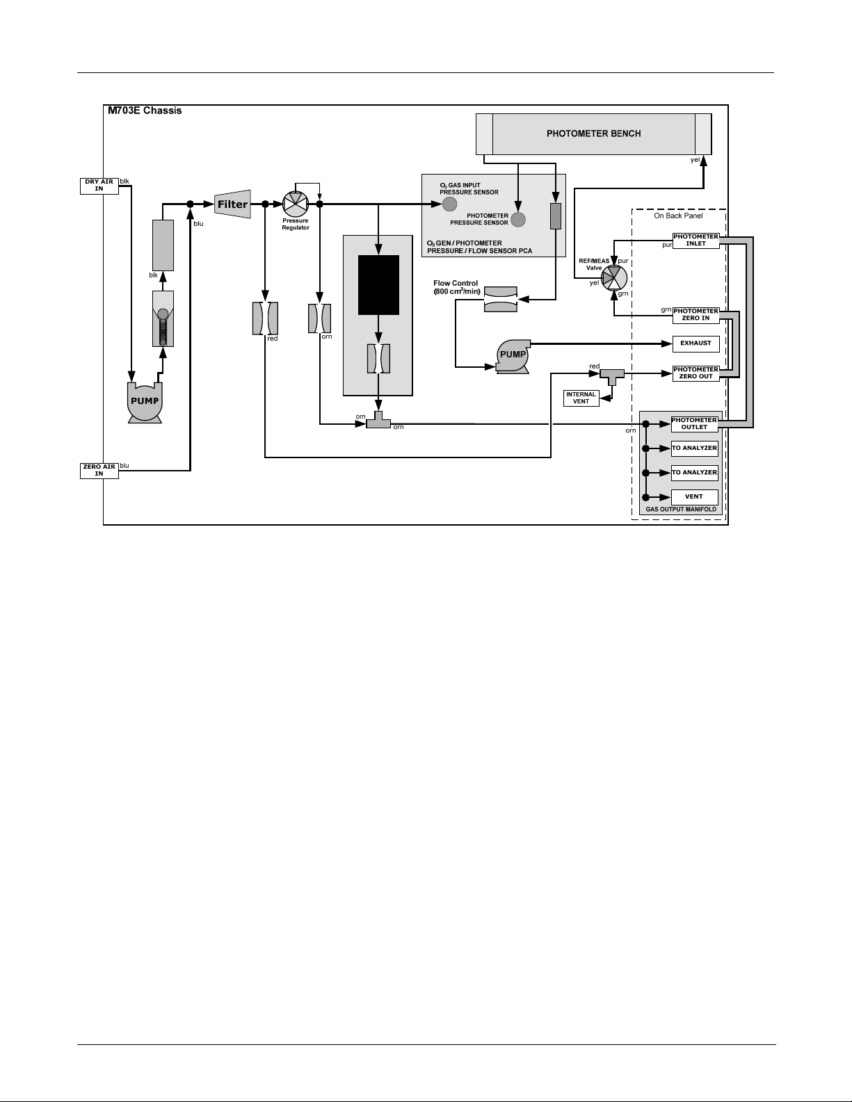
Figure 3-4: M703E Pneumatic Diagram...............................................................................................................12
Figure 3-5: M703E the TEST CHANNEL Connector ...........................................................................................13
Figure 3-6: Status Output Connector ...................................................................................................................14
Figure 3-7: M703E Digital Control Input Connectors ...........................................................................................16
Figure 3-8: M703E Digital Control Output Connector ..........................................................................................17
Figure 3-9: Basic Pneumatic Setup of M703E .....................................................................................................19
Figure 3-10: Location of Pressure Regulator Adjustment Knob.............................................................................26
Figure 5-1: M703E with Carrying Strap Handle and Rack Mount Brackets.........................................................29
Figure 5-1: M703E Multidrop Card.......................................................................................................................30
Figure 5-2: M703E Ethernet Card ........................................................................................................................31
Figure 5-3: M703E Rear Panel with Ethernet Installed........................................................................................31
Figure 6-1: Front Panel Display ...........................................................................................................................37
Figure 6-2: M703E the TEST CHANNEL Connector ...........................................................................................62
Figure 6-3: Setup for Calibrating the TEST CHANNEL .......................................................................................72
Figure 6-4: Set up for Using the M703E to Measure an External O3 Source ......................................................77
Figure 6-5: LEADS Level Display Format ............................................................................................................85
Figure 7-1: Default Pin Assignments for Back Panel COMM Port connectors (RS-232 DCE & DTE) ................88
Figure 7-2: Default Pin Assignments for CPU COM Port connector (RS-232)....................................................88
Figure 7-3: Location of JP2 on RS232-Multidrop PCA (option 62) ................................................................... 101
Figure 7-4: RS232-Multidrop PCA Host/Calibrator Interconnect Diagram........................................................ 102
Figure 7-5: CPU card Locations of RS-232/485 Switches, Connectors and Jumpers...................................... 103
Figure 7-6: Back Panel connector Pin-Outs for COM2 in RS-485 mode.......................................................... 104
Figure 7-7: CPU connector Pin-Outs for COM2 in RS-485 mode..................................................................... 104
Figure 7-8: APICOM Remote Control Program Interface ................................................................................. 111
Figure 8-1: Set up for Verifying Optional O
Figure 8-2: Set up for Verifying Optional O
Figure 8-3: Pressure Calibration Monitor Points ............................................................................................... 125
Figure 8-4: O3 Generator Pressure Monitor Point Physical Location– M703E ................................................. 126
Figure 8-5: Output Flow Calibration Monitor Point............................................................................................ 130
Figure 9-1: Location of Gas Flow Control Assemblies...................................................................................... 135
Figure 9-2: M703E Electronic Block Diagram ................................................................................................... 137
Figure 9-3: M703E CPU Board Annotated........................................................................................................ 138
Figure 9-4: Relay Board PCA with AC Relay Retainer Removed..................................................................... 140
Figure 9-5: Heater Control Loop Block Diagram............................................................................................... 141
Figure 9-6: Status LED Locations – Relay PCA ............................................................................................... 141
Figure 9-7: M703E Power Distribution Block diagram ...................................................................................... 145
Figure 9-8: Location of the AC Configuration Jumper for the Dry Air Pump.................................................... 146
Figure 9-9: Pump AC Power Jumpers (JP7).................................................................................................... 147
Figure 9-10: M703E Front Panel Layout ............................................................................................................. 147
Figure 9-11: Keyboard and Display Interface Block Diagram............................................................................. 149
Figure 9-12: Schematic of Basic Software Operation ......................................................................................... 150
Figure 9-13: O3 Generator Internal Pneumatics.................................................................................................. 151
Figure 9-14: O3 Generator Valve and Gas Fixture Locations ............................................................................. 152
Figure 9-15: O3 Generator Electronic Block Diagram ......................................................................................... 153
Figure 9-16: O3 Generator Electronic Components Location ............................................................................. 153
Figure 9-17: O3 Generator Temperature Thermistor and DC Heater Locations................................................. 154
Figure 9-18: O3 Photometer Gas Flow – Measure Cycle.................................................................................... 157
Figure 9-19: O3 Photometer Gas Flow – Reference Cycle ................................................................................. 157
Figure 9-20: O3 Photometer Absorption Path ..................................................................................................... 158
Figure 9-21: O3 Photometer Layout – Top Cover Removed............................................................................... 159
Figure 9-22: O3 Photometer Electronic Block Diagram....................................................................................... 160
Figure 10-2: Pneumatic setup for performing Pressure Leak Checks ................................................................ 170
Figure 10-3: Photometer – Location of UV Detector Gain Adjustment & UV Lamp Set Screw ........................... 173
Photometer Using Internal O
3
Photometer Using an External O
3
3
Generator .................................... 114
Generator.............................. 114
3
viii 05744 Rev B
Page 13

TELEDYNE API
M703E Calibrator Operator’s Manual Table of Contents
Figure 10-4: O3 Generator Temperature Thermistor and DC Heater Locations................................................. 174
Figure 10-5: Location of O3 Generator Reference Detector Adjustment Pot...................................................... 174
Figure 11-1: Example of Signal I/O Function ...................................................................................................... 182
Figure 11-2: CPU Status Indicator ...................................................................................................................... 184
Figure 11-3: Relay PCA Status LEDS Used for Troubleshooting....................................................................... 185
Figure 11-4: Location of DC Power Test Points on Relay PCA.......................................................................... 187
Figure 11-5: Critical Flow Restrictor Assembly Disassembly.............................................................................. 202
Figure 12-1: Triboelectric Charging..................................................................................................................... 205
Figure 12-2: Basic anti-ESD Work Station.......................................................................................................... 207
LIST OF TABLES
Table 2-1: M703E Analytical Specifications..........................................................................................................5
Table 2-2: M703E Electrical and Physical Specifications.....................................................................................5
Table 2-3: M703E Specifications for Ozone Generator........................................................................................6
Table 2-4: M703E Specifications for O3 Photometer ............................................................................................6
Table 3-1: Status Output Pin Assignments.........................................................................................................14
Table 3-2: M703E Control Input Pin Assignments..............................................................................................15
Table 3-3: M703E Control Input Pin Assignments..............................................................................................17
Table 3-4: Front Panel Display during System Warm-Up...................................................................................22
Table 3-5: Possible Warning Messages at Start-Up...........................................................................................23
Table 6-1: Test Functions Defined......................................................................................................................36
Table 6-2: Calibrator Operating Modes...............................................................................................................37
Table 6-3: Automatic Calibration SEQUENCE Set Up Attributes.......................................................................40
Table 6-4: Calibration SEQUENCE Step Instruction ..........................................................................................40
Table 6-5: Sequence Progress Reporting Mode ................................................................................................49
Table 6-6: Password Levels................................................................................................................................60
Table 6-7: DIAG - Analog I/O Functions .............................................................................................................62
Table 6-8: Test Channels Functions Available on the M703E’s Analog Output.................................................64
Table 6-9: Analog Output Voltage Range Min/Max ............................................................................................66
Table 6-10: Voltage Tolerances for the TEST CHANNEL Calibration..................................................................72
Table 6-11: Variable Names (VARS)....................................................................................................................75
Table 7-1: COMM Port Communication Modes..................................................................................................91
Table 7-2: Terminal Mode Software Commands ................................................................................................95
Table 7-3: Teledyne Instruments Serial I/O Command Types............................................................................96
Table 7-4: Ethernet Status Indicators .............................................................................................................. 105
Table 7-5: LAN/Internet Configuration Properties............................................................................................ 106
Table 8-1: M703E Pressure Sensors............................................................................................................... 125
Table 8-2: M703E Gas Pressure to Output Flow conversion Table ................................................................ 128
Table 9-1: Relay Board Status LEDs ............................................................................................................... 142
Table 9-2: AC Power Configuration for Internal Pumps (JP7)......................................................................... 146
Table 9-3: Front Panel Status LEDs ................................................................................................................ 148
Table 9-4: M703E Photometer Measurement / Reference Cycle.................................................................... 156
Table 10-1: M703E Maintenance Schedule....................................................................................................... 165
Table 11-1: Front Panel Warning Messages ..................................................................................................... 179
Table 11-2: Test Functions - Indicated Failures ................................................................................................ 180
Table 11-3: Test Channel Outputs as Diagnostic Tools .................................................................................... 183
Table 11-4: Relay PCA Watchdog LED Failure Indications............................................................................... 184
Table 11-5: Relay PCA Status LED Failure Indications..................................................................................... 185
Table 11-6: DC Power Test Point and Wiring Color Codes............................................................................... 187
Table 11-7: DC Power Supply Acceptable Levels............................................................................................. 188
Table 11-8: Relay PCA Control Devices............................................................................................................ 189
Table 11-9: Analog Output Test Function - Nominal Values Voltage Outputs .................................................. 192
Table 11-10: Status Outputs Check..................................................................................................................... 192
Table 11-11: M703E Control Input Pin Assignments and Corresponding Signal I/O Functions ......................... 193
05744 Rev B ix
Page 14

TELEDYNE API
Table of Contents M703E Calibrator Operator’s Manual
Table 11-12: Control Outputs Pin Assignments and Corresponding Signal I/O Functions Check...................... 194
Table 12-1: Static Generation Voltages for Typical Activities............................................................................ 205
Table 12-2: Sensitivity of Electronic Devices to Damage by ESD..................................................................... 206
x 05744 Rev B
Page 15

TELEDYNE API
M703E Calibrator Operator’s Manual Table of Contents
LIST OF APPENDICES
APPENDIX A - VERSION SPECIFIC SOFTWARE DOCUMENTATION
APPENDIX A-1: Model 703E Software Menu Trees, Revision C.0
APPENDIX A-2: Model 703E Setup Variables Available Via Serial I/O, Revision C.0
APPENDIX A-3: Model 703E Warnings and Test Measurements via Serial I/O, Revision C.0
APPENDIX A-4: Model 703E Signal I/O Definitions, Revision C.0
APPENDIX A-5: Model 703E Terminal Command Designators, Revision C.0
APPENDIX B - Model 703E SPARE PARTS LIST
APPENDIX C - Model 703E REPAIR QUESTIONNAIRE
APPENDIX D - Model 703E ELECTRONIC SCHEMATICS
USER NOTES:
05744 Rev B xi
Page 16

TELEDYNE API
Table of Contents M703E Calibrator Operator’s Manual
USER NOTES:
xii 05744 Rev B
Page 17

TELEDYNE API
M703E Calibrator Operator’s Manual GENERAL INFORMATION
SECTION I
–
GENERAL INFORMATION
05744 Rev B 1
Page 18

TELEDYNE API
GENERAL INFORMATION M703E Calibrator Operator’s Manual
USER NOTES
2 05744 Rev B
Page 19

TELEDYNE API
M703E Calibrator Operator’s Manual Introduction
1. INTRODUCTION
1.1. M703E CALIBRATOR OVERVIEW
The Model 703E is a microprocessor-based ozone calibrator for calibration of ambient ozone analyzers, such as
the T-API M400E. The M703E features an internal ozone photometer that provides very accurate closed loop
feedback control of the ozone concentration.
As many as 50 independent calibration sequences may be programmed into the M703E, covering time periods
of up to one year. The setup of sequences is simple and intuitive. These sequences may be actuated manually,
automatically, or by a remote signal. The sequences may be uploaded remotely, including remote editing. All
programs are maintained in non-volatile memory.
The M703E design emphasizes fast response, repeatability, overall accuracy and ease of operation. It may be
combined with the Model 701 Zero Air Generator to provide the ultimate in easy to use, precise calibration for
your ozone analyzers.
Some of the exceptional features of your M703E Photometric O3 Calibrator are:
Advanced E Series electronics
Lightweight for transportability
Optional Ethernet connectivity
12 independent timers for sequences
Nested sequences (up to 5 levels)
Internal ozone generator and photometer allows use as primary or transfer standard
1.2. USING THIS MANUAL
NOTE
Throughout this manual, words printed in capital, bold letters, such as SETUP or ENTR represent
messages as they appear on the calibrator’s display.
This manual is organized in the following manner:
TABLE OF CONTENTS:
Outlines the contents of the manual in the order the information is presented. This is a good overview of the
topics covered in the manual. There is also a list of appendices, figures and tables. In the electronic version of
the manual, clicking on any of these table entries automatically views that section.
SECTION I – GENERAL INFORMATION
INTRODUCTION
A brief description of the M703E calibrator architecture as well as a description of the layout of the
manual and what information is located in its various sections and chapters.
SPECIFICATIONS AND WARRANTY
Teledyne Instruments’ warranty statement.
05744 Rev B 3
Page 20

TELEDYNE API
Introduction M703E Calibrator Operator’s Manual
GETTING STARTED
Instructions for setting up, installing and running your calibrator for the first time.
GLOSSARY:
Answers to the most frequently asked questions about operating the calibrator and a glossary of
acronyms and technical terms.
OPTIONAL HARDWARE & SOFTWARE
A description of optional equipment to add functionality to your calibrator.
SECTION II – OPERATING INSTRUCTIONS
USING THE M703E CALIBRATOR
Step-by-Step instructions for using the display/keyboard to set up and operate the M703E calibrator.
REMOTE OPERATION OF THE M703E CALIBRATOR
Information and instructions for interacting with the M703E calibrator via its several remote interface
options (e.g. via RS-232, Ethernet, its built in digital control inputs/outputs, etc.)
M703E VALIDATION AND VERIFICATION
Methods and procedures for validating and verifying the correct operation of your M703E Photometric O3
Calibrator
SECTION III – TECHNICAL INFORMATION
THEORY OF OPERATION
An in-depth look at the various principals by which your calibrator operates as well as a description of
how the various electronic, mechanical and pneumatic components of the calibrator work and interact
with each other. A close reading of this section is invaluable for understanding the calibrator’s
operation.
MAINTENANCE SCHEDULE AND PROCEDURES
Description of preventative maintenance procedures that should be regularly performed on you
calibrator to assure good operating condition.
GENERAL TROUBLESHOOTING & REPAIR OF THE M703E CALIBRATOR
This section includes pointers and instructions for diagnosing problems with the calibrator in general as
well as instructions on performing repairs.
A PRIMER ON ELECTRO-STATIC DISCHARGE
This section describes how static electricity occurs; why it is a significant concern and; how to avoid it
and avoid allowing ESD to affect the reliable and accurate operation of your calibrator.
APPENDICES
For easier access and better updating, some information has been separated out of the manual and placed in a
series of appendices at the end of this manual. These include version-specific software menu trees, warning
messages, serial I/O variables as well as spare part listings, repair questionnaires, interconnect drawing,
detailed pneumatic and electronic schematics.
USER NOTES:
4 05744 Rev B
Page 21

TELEDYNE API
M703E Calibrator Operator’s Manual Specifications, Approvals and Warranty
2. SPECIFICATIONS, APPROVALS AND
WARRANTY
2.1. SPECIFICATIONS
Table 2-1: M703E Analytical Specifications
Linearity
Precision
Stability
Response Time 180 seconds to 95%
Stability (7-days) 1% photometer feedback; 3% without photometer feedback (CNST or REF)
+/- 1.0% of full scale
1.0 ppb
+/- 2.0 ppb (photometer feedback mode)
Table 2-2: M703E Electrical and Physical Specifications
Temperature Range 5-40ºC
Humidity Range 0 - 95% RH, non-condensing
Dimensions (HxWxD) 7” (178 mm) x 17” (432 mm) x 24” (609 mm)
Operating Altitude 10,000 ft Maximum
Weight
AC Power
Analog Outputs 1 user configurable output
Analog Output Ranges
Analog Output Resolution 1 part in 4096 of selected full-scale voltage (12 bit)
Digital Control Outputs 12 opto-isolated outputs
Digital Control Inputs 12 opto-isolated outputs
Status Outputs 12 opto-isolated outputs, 5 defined, 7 spare
Serial I/O
Certifications
35.5 lbs (16.1 kg) including internal zero air pump
115VAC, 60Hz
230VAC,50HZ
0.1 V, 1 V, 5 V or 10 V
Range with 5% under/over-range
2 ports: 1x RS-232; 1x RS-485 or RS-232 (configurable)
Communication speed: 300 - 115200 baud (user selectable)
EN61326 (1997 w/A1: 98) Class A, FCC Part 15 Subpart B Section 15.107 Class
A, ICES-003 Class A (ANSI C63.4 1992) & AS/NZS 3548 (w/A1 & A2; 97)
Class A.
IEC 61010-1:90 + A1:92 + A2:95,
05744 Rev B 5
Page 22

TELEDYNE API
Specifications, Approvals and Warranty M703E Calibrator Operator’s Manual
Table 2-3: M703E Specifications for Ozone Generator
Maximum Output 6 ppm LPM
Minimum Output 100 ppb LPM
Response Time: 180 Sec. (98%)
Optical Feedback Standard
Table 2-4: M703E Specifications for O
Full Scale Range 100 ppb to 10 ppm ; User Selectable
Precision 1.0 ppb
Linearity 1.0% of Full Scale
Rise/Fall Time <20 sec (photometer response)
Zero Drift <1.0 ppb / 7 days
Span Drift <1% / 24 hours; <2% / 7 days
Minimum Gas Flow Required 800 cc3/min
Photometer
3
2.2. CE MARK COMPLIANCE
EMISSIONS COMPLIANCE
The Teledyne Instruments’ M703E Photometric O3 Calibrator is designed to be fully compliant with:
EN61326 (1997 w/A1: 98) Class A, FCC Part 15 Subpart B Section 15.107 Class A, ICES-003 Class A (ANSI
C63.4 1992) & AS/NZS 3548 (w/A1 & A2; 97) Class A.
Test status: Pending.
SAFETY COMPLIANCE
The Teledyne Instruments’ M703E Photometric O3 Calibrator is designed to be fully compliant with:
IEC 61010-1:90 + A1:92 + A2:95,
Test status: Pending.
6 05744 Rev B
Page 23

TELEDYNE API
M703E Calibrator Operator’s Manual Specifications, Approvals and Warranty
2.3. WARRANTY
WARRANTY POLICY (02024D)
Prior to shipment, T-API equipment is thoroughly inspected and tested. Should equipment failure occur, T-API
assures its customers that prompt service and support will be available.
COVERAGE
After the warranty period and throughout the equipment lifetime, T-API stands ready to provide on-site or in-plant
service at reasonable rates similar to those of other manufacturers in the industry. All maintenance and the first
level of field troubleshooting is to be performed by the customer.
NON-API MANUFACTURED EQUIPMENT
Equipment provided but not manufactured by T-API is warranted and will be repaired to the extent and according
to the current terms and conditions of the respective equipment manufacturers warranty.
GENERAL
During the warranty period, T-API warrants each Product manufactured by T-API to be free from defects in
material and workmanship under normal use and service. Expendable parts are excluded.
If a Product fails to conform to its specifications within the warranty period, API shall correct such defect by, in
API's discretion, repairing or replacing such defective Product or refunding the purchase price of such Product.
The warranties set forth in this section shall be of no force or effect with respect to any Product: (i) that has been
altered or subjected to misuse, negligence or accident, or (ii) that has been used in any manner other than in
accordance with the instruction provided by T-API, or (iii) not properly maintained.
THE WARRANTIES SET FORTH IN THIS SECTION AND THE REMEDIES THEREFORE ARE EXCLUSIVE
AND IN LIEU OF ANY IMPLIED WARRANTIES OF MERCHANTABILITY, FITNESS FOR PARTICULAR
PURPOSE OR OTHER WARRANTY OF QUALITY, WHETHER EXPRESSED OR IMPLIED. THE REMEDIES
SET FORTH IN THIS SECTION ARE THE EXCLUSIVE REMEDIES FOR BREACH OF ANY WARRANTY
CONTAINED HEREIN. API SHALL NOT BE LIABLE FOR ANY INCIDENTAL OR CONSEQUENTIAL
DAMAGES ARISING OUT OF OR RELATED TO THIS AGREEMENT OF T-API'S PERFORMANCE
HEREUNDER, WHETHER FOR BREACH OF WARRANTY OR OTHERWISE
TERMS AND CONDITIONS
All units or components returned to Teledyne Instruments Incorporated should be properly packed for handling
and returned freight prepaid to the nearest designated Service Center. After the repair, the equipment will be
returned, freight prepaid.
USER NOTES:
05744 Rev B 7
Page 24

TELEDYNE API
Specifications, Approvals and Warranty M703E Calibrator Operator’s Manual
USER NOTES:
8 05744 Rev B
Page 25
TELEDYNE API
M703E Calibrator Operator’s Manual Getting Started
3. GETTING STARTED
3.1. UNPACKING AND INITIAL SETUP
CAUTION
THE M703E WEIGHS ABOUT 16.1 KG (35.5 POUNDS) WITHOUT OPTIONS
INSTALLED. TO AVOID PERSONAL INJURY, WE RECOMMEND USING TWO
1. Inspect the received packages for external shipping damage. If damaged, please advise the shipper
first, then Teledyne Instruments.
2. Included with your calibrator is a printed record of the final performance characterization performed on
your instrument at the factory. This record, titled Final Test and Validation Data Sheet
important quality assurance and calibration record for this instrument. It should be placed in the quality
records file for this instrument.
3. Carefully remove the top cover of the calibrator and check for internal shipping damage.
Remove the set-screw located in the top, center of the Front panel.
PERSONS TO LIFT AND CARRY THE CALIBRATOR.
(P/N 05760) is an
Remove the 2 screws fastening the top cover to the unit (one per side towards the rear).
Slide the cover backwards until it clears the calibrator’s front bezel.
Lift the cover straight up.
NOTE
Printed circuit assemblies (PCAs) are sensitive to electro-static discharges too small to be felt by the
human nervous system. Failure to use ESD protection when working with electronic assemblies will
void the instrument warranty.
See Chapter 12 for more information on preventing ESD damage.
CAUTION
NEVER DISCONNECT ELECTRONIC CIRCUIT BOARDS, WIRING HARNESSES OR
4. Inspect the interior of the instrument to make sure all circuit boards and other components are in good
shape and properly seated.
5. Check the connectors of the various internal wiring harnesses and pneumatic hoses to make sure they
are firmly and properly seated.
ELECTRONIC SUBASSEMBLIES WHILE THE UNIT IS UNDER POWER.
6. Verify that all of the optional hardware ordered with the unit has been installed. These are checked on
the paperwork accompanying the calibrator.
05744 Rev B 9
Page 26
TELEDYNE API
Getting Started M703E Calibrator Operator’s Manual
VENTILATION CLEARANCE: Whether the calibrator is set up on a bench or installed into an instrument rack,
be sure to leave sufficient ventilation clearance.
AREA MINIMUM REQUIRED CLEARANCE
Back of the instrument 10 cm / 4 inches
Sides of the instrument 2.5 cm / 1 inch
Above and below the instrument. 2.5 cm / 1 inch
Various rack mount kits are available for this calibrator. See Chapter 5 of this manual for more information.
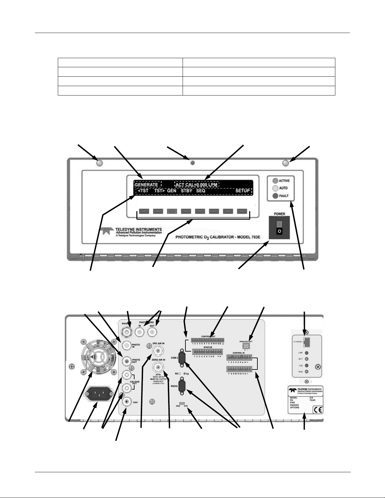
3.1.1. MODEL 703E CALIBRATOR
FASTENER
KEY DEFINITION FIELD
MODE FIELD
LOCKING SCREW
KEYBOARD
MESSAGE FIELD
ON / OFF SWITCH
FASTENER
STATUS LED’s
Figure 3-1: M703E Front Panel Layout
O3 Outlet to
Photometer
Photometer
Inlet
O
3
O3 Generator
Exhaust
PhotometerGas
Connectors
Status Outputs
Control Outputs
Analog Output
Optional Ethernet
Card
FAN
AC Pow er
Connector
Cal Gas
Outlets
Inlet for
Dry Air
Inlet for External
Zero Air Source
DCE-DTE
Switch
COMM Ports
Control Inputs
Serial No. Tag
Figure 3-2: M703E Rear Panel Layout
10 05744 Rev B
Page 27
TELEDYNE API
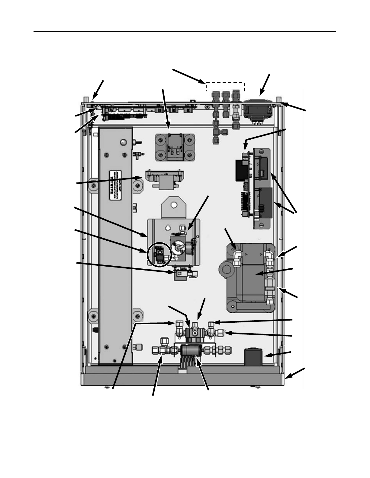
A
r
r
M703E Calibrator Operator’s Manual Getting Started
Motherboard
CPU PCA
O3 Generator &
Photometer,
Pressure/Flow
Sensor PC
O3 Generato
Assembly
Photometer
M/R Valve
O
Generator
3
Lamp Drive
Ethernet PCA
installed here
(Optional)
Gas Inlets & Outlets
Photometer
Pump
O3 Generator
Dry Air
Pump Inlet
AC Power
Connector
Back Panel
Relay PCA
DC Power
supplies
Dry Air
Pump
Outlet
Dry Air
Pump
PHOTOMETER
5 LPM
Flow Control
Assy.
Pressure
Regulator
Inlet
Pressure
Regulator
Inlet
Outlet to O
Generator
DFU Filters
Scrubber on
3
Charcoal
Top
Check
Valve
1 LPM Flow
Control Assy.
Inlet to
Regulator
ON / OFF
Switch
Front Panel
Figure 3-3: M703E Internal Layout – Top View
05744 Rev B 11
Page 28
TELEDYNE API
Getting Started M703E Calibrator Operator’s Manual
O
SENSOR
3
FLOW
CHARCOAL
SCRUBBER
GENERATOR
O
O
3
3
(1.0 to 2.0 LPM)
Flow Control
Flow Control
(5.0 lpm)
(100 cm
Flow Control
3
/min)
Generator Assembly
Figure 3-4: M703E Pneumatic Diagram
12 05744 Rev B
Page 29
TELEDYNE API
–
M703E Calibrator Operator’s Manual Getting Started
3.2. ELECTRICAL CONNECTIONS
3.2.1. POWER CONNECTION
Verify the correct line voltage and frequency configuration on the serial number tag on the rear panel of the
M703E.
Attach the power cord to the calibrator and plug it into a power outlet capable of carrying at least 10 A current at
your AC voltage and that it is equipped with a functioning earth ground.
CAUTION
HIGH VOLTAGES ARE PRESENT INSIDE THE CALIBRATORS CASE
POWER CONNECTION MUST HAVE FUNCTIONING GROUND CONNECTION.
DO NOT DEFEAT THE GROUND WIRE ON POWER PLUG.
TURN OFF CALIBRATOR POWER BEFORE DISCONNECTING OR
CONNECTING ELECTRICAL SUBASSEMBLIES.
CAUTION
DO NOT LOOK AT THE PHOTOMETER UV LAMP.
UV LIGHT CAN CAUSE EYE DAMAGE.
ALWAYS WEAR GLASSES MADE FROM SAFETY UV FILTERING GLASS
(PLASTIC GLASSES WILL NOT DO).
3.2.2. ANALOG OUTPUT TEST CHANNEL CONNECTIONS
The M703E is equipped with an analog output channel accessible through a connector on the back panel of the
instrument. The standard configuration for this output is 0-5 VDC. It can be set by the user to output one of a
variety of diagnostic test functions (see Section 6.9.)
To acce
connections on the rear panel of the calibrator.
ss these
signals attach a strip chart recorder and/or data-logger to the appropriate analog output
Pin-outs for the analog output connector at the rear panel of the instrument are:
ANALOG OUT
+
Figure 3-5: M703E the TEST CHANNEL Connector
05744 Rev B 13
Page 30
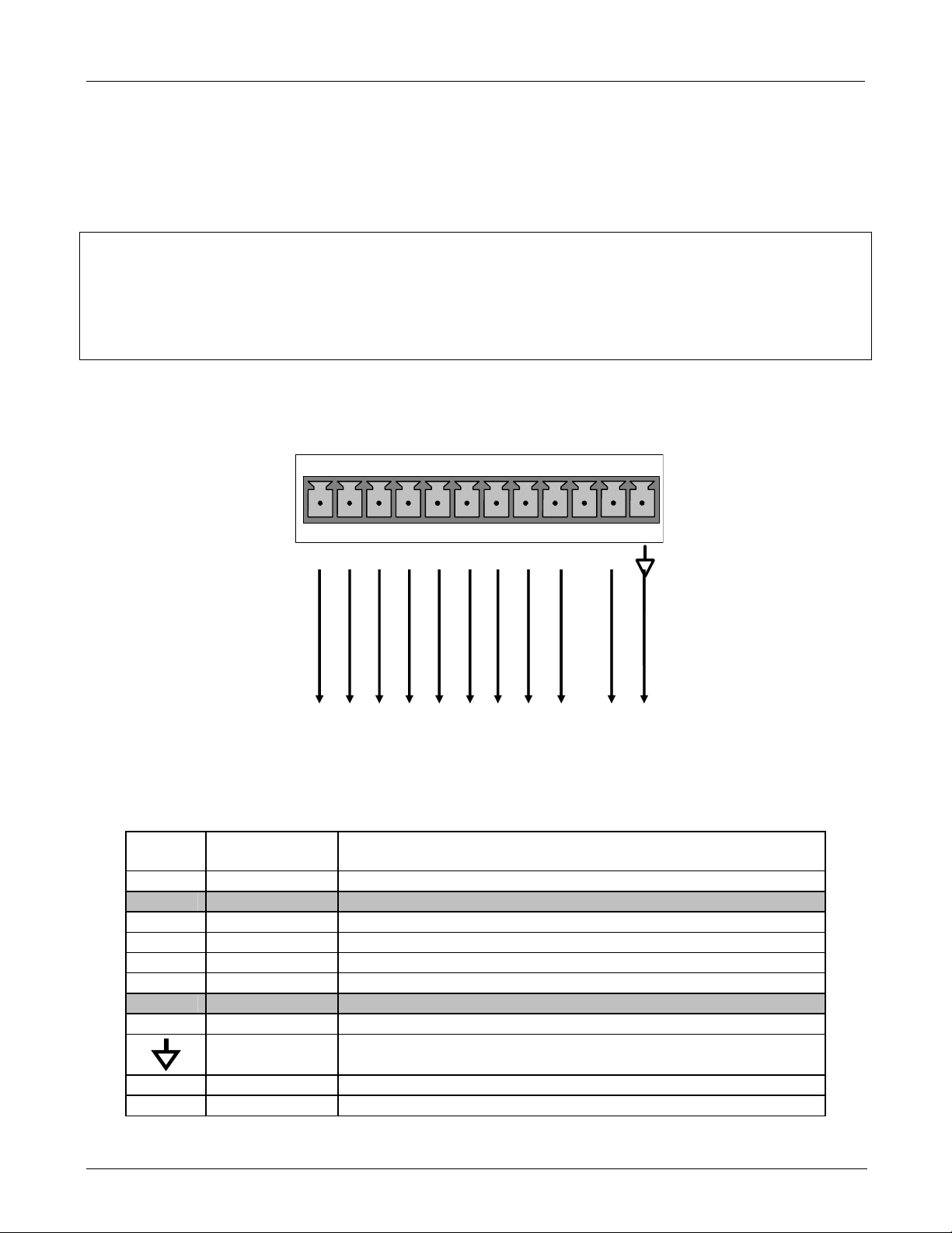
TELEDYNE API
Getting Started M703E Calibrator Operator’s Manual
3.2.3. CONNECTING THE STATUS OUTPUTS
The status outputs report calibrator conditions via optically isolated NPN transistors, which sink up to 50 mA of
DC current. These outputs can be used interface with devices that accept logic-level digital inputs, such as
programmable logic controllers (PLC’s). Each Status bit is an open collector output that can withstand up to 40
VDC. All of the emitters of these transistors are tied together and available at D.
NOTE
Most PLC’s have internal provisions for limiting the current that the input will draw from an external
device. When connecting to a unit that does not have this feature, an external dropping resistor must be
used to limit the current through the transistor output to less than 50 mA. At 50 mA, the transistor will
drop approximately 1.2V from its collector to emitter.
The status outputs are accessed via a 12-pin connector on the calibrator’s rear panel labeled STATUS. The
function of each pin is defined in Table 3-1.
1 2 3 4 5 6 7 8 D +
DIAG
POWER OK
SYSTEM OK
CAL ACTIVE
Figure 3-6: Status Output Connector
The pin assignments for the Status Outputs are:
Table 3-1: Status Output Pin Assignments
OUTPUT
#
1
2 Unassigned
3
4
5
6
7 & 8 Unassigned
D Emitter BUSS The emitters of the transistors on pins 1 to 8 are bussed together.
STATUS
DEFINITION
SYSTEM OK
CAL ACTIVE On if the calibrator is in GENERATE mode
DIAG On if the calibrator is in DIAGNOSTIC mode
TEMP ALARM
PRESS ALARM
On, if no faults are present.
On whenever a temperature alarm is active.
On whenever gas pressure alarm is active
STATUS
TEMP ALARM
PRESS ALARM
Unassigned
Unassigned
EMITTER BUSS
CONDITION
+ 5 VDC
CALIBRATOR
INRTERNAL GROUND
Digital Ground The ground level from the calibrator’s internal DC power supplies.
D Emitter BUSS The emitters of the transistors on pins 9 to 16 are bussed together.
+ DC POWER + 5 VDC
14 05744 Rev B
Page 31

TELEDYNE API
M703E Calibrator Operator’s Manual Getting Started
3.2.4. CONNECTING THE CONTROL INPUTS
The calibrator is equipped with 12 digital control inputs that can be used to Initiate various user programmable
calibration sequences (see Section 6.5.1.5 for instructions on assigning the control inputs to specific
sequences).
Access to these inputs is via 2 separate 10-pin connectors, labeled CONTROL IN, that are located on the
calibrator’s rear panel.
Table 3-2: M703E Control Input Pin Assignments
CONNECTOR INPUT DESCRIPTION
Top 1 to 6
Bottom 7 to 12
BOTH
Top U
Bottom U
BOTH
+
Can be used as either 6 separate on/off switches or as bits 1 through
6 of a 12 bit wide binary activation code (see Section 6.5.1.5)
Can be used as either 6 separate on/off switches or as bits 7 through
12 of a 12 bit wide binary activation code (see Section 6.5.1.5)
Chassis ground.
Input pin for +5 VDC required to activate pins A – F. This can be from
an external source or from the “+” pin of the instruments STATUS
connector.
Input pin for +5 VDC required to activate pins G – L. This can be from
an external source or from the “+” pin of the instruments STATUS
connector.
Internal source of +5V that can be used to actuate control inputs when
connected to the U pin.
calibration
05744 Rev B 15
Page 32

TELEDYNE API
Getting Started M703E Calibrator Operator’s Manual
There are two methods for energizing the control inputs. The internal +5V available from the pin labeled “+” is
the most convenient method. However, if full isolation is required, an external 5 VDC power supply should be
used.
Example of Local Power Connections Example of External Power Connections
CONTROL Bit-01
CONTROL Bit-02
CONTROL Bit-03
CONTROL Bit-04
CONTROL Bit-05
CONTROL Bit-06
CONTROL Bit-01
CONTROL Bit-02
CONTROL Bit-03
CONTROL Bit-04
CONTROL Bit-05
CONTROL Bit-06
1 2 3 4 5 6 U +
7 8 9 10 11 12 U +
CONTROL Bit-07
CONTROL Bit-08
CONTROL Bit-09
CONTROL Bit-10
CONTROL Bit-12
CONTROL Bit-11
Figure 3-7: M703E Digital Control Input Connectors
1 2 3 4 5 6 U +
7 8 9 10 11 12 U +
CONTROL Bit-07
CONTROL Bit-08
CONTROL Bit-09
CONTROL Bit-10
CONTROL Bit-11
CONTROL Bit-12
-
5 VDC Power
Supply
+
16 05744 Rev B
Page 33

TELEDYNE API
M703E Calibrator Operator’s Manual Getting Started
3.2.5. CONNECTING THE CONTROL OUTPUTS
The calibrator is equipped with 12 opto-isolated, digital control outputs. These outputs are activated by the
M703E’s user-programmable, calibration sequences (see Section 6.5.1.6 for instructions on assigning the
control outputs to spe
These outputs may be used to interface with devices that accept logic-level digital inputs, such as programmable
logic controllers (PLC’s), dataloggers, or digital relays/valve drivers.
They are accessed via a 14-pin connector on the calibrator’s rear panel (see Figure 3-2).
cific calibration sequences)
CONTROL OUTPUTS
1 2 3 4 5 6 7 8 9 10 11 12 E
Figure 3-8: M703E Digital Control Output Connector
NOTE
Most PLC’s have internal provisions for limiting the current the input will draw. When connecting to a
unit that does not have this feature, external resistors must be used to limit the current through the
individual transistor outputs to ≤50mA (120 Ω for 5V supply).
The pin assignments for the control outputs are:
Table 3-3: M703E Control Input Pin Assignments
PIN # STATUS DEFINITION CONDITION
1 - 12 Outputs 1 through 12 respectively Closed if the sequence or sequence step activating output is operating
E Emitter BUSS The emitters of the transistors on pins 1 to 8 are bussed together.
Digital Ground The ground level from the calibrator’s internal DC power supplies.
05744 Rev B 17
Page 34

TELEDYNE API
Getting Started M703E Calibrator Operator’s Manual
3.2.6. CONNECTING THE SERIAL PORTS
If you wish to utilize either of the calibrator’s two serial interface COMM ports, refer to Section 7.1 of this manual
for instructions on their configuration and usage.
3.2.7. CONNECTING TO A LAN OR THE INTERNET
If your unit has a Teledyne Instruments Ethernet card (Option 63 and 64), plug one end into the 7’ CAT5 cable
supplied with the option into the appropriate place on the back of the calibrator and the other end into any
nearby Ethernet access port.
NOTE:
The M703E firmware supports dynamic IP addressing or DHCP.
If your network also supports DHCP, the calibrator will automatically configure its LAN connection
appropriately,
If your network does not support DHCP, see Section 7.5.2.1 for instructions on manually configuring the
LAN connection.
3.2.8. CONNECTING TO A MULTIDROP NETWORK
If your unit has a Teledyne Instruments RS-232 multidrop card (Option 62), see Section 7.3 for instructions on
setting it up.
18 05744 Rev B
Page 35

TELEDYNE API
M703E Calibrator Operator’s Manual Getting Started
3.3. PNENUMATIC CONNECTIONS
Figure 3-9: Basic Pneumatic Setup of M703E
3.3.1. DRY AIR IN
When using the internal zero air pump, a source of dry air should be connected to the port labeled ‘Dry Air In’ on
the rear panel. This air should be supplied at atmospheric pressure. The supplied air should have a dew point
of –20 C or less.
Teledyne API can supply an optional desiccant cartridge that can be used to supply dry air to the M703E.
3.3.2. ZERO AIR IN
An external pressurized source of zero air can be supplied at the ‘Zero Air” port on the rear panel. This is the
standard configuration when the zero air pump is not installed. This zero air should be scrubbed of ozone and
have a dew point of -20 C or less. The pressure of the zero air should be regulated to 20-35 psig.
NOTE
When connecting an external source of zero air to an M703E with an internal zero air pump installed, the
zero air pump should be disabled.
The “ZA_PUMP_ENABLE” VAR (see Section 6.10) should be set to OFF.
05744 Rev B 19
Page 36

TELEDYNE API
Getting Started M703E Calibrator Operator’s Manual
3.3.3. OUTPUT MANIFOLD
A four-port output manifold is supplied on the rear panel of the M703E enabling simultaneous testing of up to two
external analyzers. Sample lines for ozone analyzers to be calibrated can be connected directly to this manifold.
To prevent ozone exposure, the bottom port of this manifold is used as a vent and should be connected to a
proper unpressurized vent manifold. It is important that the backpressure at this vent fitting be kept to a
minimum. If a vent line longer than 2 meters (~6 feet) is required, then 3/8” OD tubing should be used.
Any unused ports on this manifold must be capped.
3.3.4. EXHAUST
The port labeled ‘EXHAUST’ contains the exhaust gas from the internal photometer and may contain ozone.
This port should be connected to a proper unpressurized vent manifold to prevent ozone exposure.
3.3.5. MEASURING AN EXTERNAL OZONE SOURCE
The M703E can easily be configured to measure an external source of ozone.
See Section 6.11 for details on operating the M703E in this manner.
USER NOTES
20 05744 Rev B
Page 37

TELEDYNE API
M703E Calibrator Operator’s Manual Getting Started
3.4. INITIAL OPERATION
If you are unfamiliar with the M703E theory of operation, we recommend that you read Chapter 9.
For information on navigating the calibrator’s software menus, see the menu trees described in Appendix A.1.
3.4.1. START-UP
After all of the electrical and pneumatic connections are made, turn on the instrument. The exhaust fan and
should start immediately. If the instrument is equipped with an internal photometer installed, the associated
pump should also start up.
The display should immediately display a single, horizontal dash in the upper left corner of the display. This will
last approximately 30 seconds while the CPU loads the operating system.
Once the CPU has completed this activity, it will begin loading the calibrator firmware and configuration data.
During this process, string of messages will appear on the calibrator’s front panel display:
SELECT START OR REMO TE : 3
START .
CHECKING FLASH STATUS : 1
STARTING INSTRUMENT CODE : 1
STARTING INSTRUMENT W/FLASH : 1
M703E CALIBRATOR
BOOT PROGRESS [XXXXX 50%_ _ _ _ _]
SOFTWARE REVISION B.0
BOOT PROGRESS [XXXXXXXX 80% _ _]
System waits 3 seconds
then automatically begins its
initialization routine.
No action required.
System is checking the format of
the instrument’s flash memory
**FLASH FORMAT INVALID**
appears, contact T–API customer service
The instrument is loading
configuration and calibration
data from the flash chip
The instrument is loading
the calibrator firmware.
The revision level of the
firmware installed in your
analyzer is briefly displayed
chip.
If at this point,
STANDBY SYSTEM RESET
TEST GEN STBY SEQ MSG CLR SETUP
Press CLR to clear initial
warning messages.
Firmware fully
booted
The calibrator should automatically switch to STANDBY mode after completing the boot-up sequence.
05744 Rev B 21
Page 38

TELEDYNE API
Getting Started M703E Calibrator Operator’s Manual
3.4.2. WARM UP
The M703E Photometric calibrator requires a minimum of 30 minutes for all of its internal components to reach a
stable operating temperature. During that time, various portions of the instrument’s front panel will behave as
follows. See Figure 3-1 for locations.
Table 3-4: Front Panel Display during System Warm-Up
Name Color Behavior Significance
Main Message
Field
Mode Field N/A
N/A
Displays Warning
messages and Test
Function values
Displays
“STANDBY”
STATUS LEDs
Active Green OFF
Auto Yellow OFF
Fault Red BLINKING
At initial start up the various warning messages will appear
here (see Section 3.4.3 below).
Instrument is in STANDBY mode.
Unit is operating in STANDBY mode.
This LED glows green when the instrument is actively
producing calibration gas.
This LED only glows when the calibrator is performing an automatic
calibration sequence.
The calibrator is warming up and therefore many of its subsystems
are not yet operating within their optimum ranges. Various warning
messages will appear.
3.4.3. WARNING MESSAGES
Because internal temperatures and other conditions may be outside be specified limits during the calibrator’s
warm-up period, the software will suppress most warning conditions for 30 minutes after power up. If warning
messages persist after the 30 minutes warm up period is over, investigate their cause using the troubleshooting
guidelines in Chapter 11 of this manual.
To view and clear warning messages, press:
Suppresses the
warning messages
Once the last warning has
been cleared, the MESSAGE
FIELD will return to displaying
the currently selected TEST
FUNCTION and value.
STANDBY SYSTEM RESET
TEST GEN STBY SEQ MSG CLR SETUP
STANDBY SYSTEM RESET
TEST GEN STBY SEQ MSG CLR SETUP
STANDBY SYSTEM RESET
TEST GEN STBY SEQ MSG CLR SETUP
SYSTEM ANALOG CAL WARNING
TEST CLR SETUP
STANDBY ACT =STANDBY
<TST TST> GEN STBY SEQ SETUP
MSG returns the active
warnings to the message
Press CLR to clear the current
If more than one warning is
active, the next message will take
If a warning message persists after
several attempts to clear it, the message
may indicate a real problem and not an
field.
message.
its place.
NOTE:
artifact of the warm-up period
Table 3-5 lists brief descriptions of the warning me
ssages that may occur during start up.
22 05744 Rev B
Page 39

TELEDYNE API
M703E Calibrator Operator’s Manual Getting Started
Table 3-5: Possible Warning Messages at Start-Up
MESSAGE MEANING
ANALOG CAL WARNING
CONFIG INITIALIZED
DATA INITIALIZED
FRONT PANEL WARN
LAMP DRIVER WARN
O3 GEN LAMP TEMP WARNING
O3 GEN REFERENCE WARNING
O3 PUMP WARNING
PHOTO LAMP TEMP WARNING
PHOTO REFERENCE WARNING
REAR BOARD NOT DET
RELAY BOARD WARN
SYSTEM RESET
The calibrator’s A/D converter or at least one analog
input channel has not been calibrated.
Stored Configuration information has been reset to the
factory settings or has been erased.
The calibrator’s data storage was erased.
The firmware is unable to communicate with the front
panel.
The firmware is unable to communicate with either the
O
generator or photometer lamp I2C driver chips.
3
The O3 generator lamp temperature is outside of
allowable limits.
The O3 generator’s reference detector has dropped
below the minimum allowable limit.
The pump associated with the O3 photometer has failed
to turn on.
The photometer lamp temperature is outside of
allowable limits.
The photometer reference reading is outside of
allowable limits.
The calibrator’s motherboard was not detected during
power up.
The firmware is unable to communicate with the
calibrator’s relay board.
The calibrator has been turned off and on or the CPU
was reset.
05744 Rev B 23
Page 40

TELEDYNE API
Getting Started M703E Calibrator Operator’s Manual
3.4.4. FUNCTIONAL CHECK
7. After the calibrator’s components have warmed up for at least 30 minutes, verify that the software
properly supports any hardware options that are installed.
8. Check to make sure that the calibrator is functioning within allowable operating parameters. Appendix C
includes a list of test functions viewable from the calibrator’s front panel as well as their expected values.
These functions are also useful tools for diagnosing problems with your calibrator (see Section7.5.2).
The enclosed Final Test and Validation Data sheet (part number 05760) lists these values before the
instrument left the factory.
To view the current values of these parameters press the following key sequence on the calibrator’s front
panel. Remember until the unit has completed its warm up these parameters may not have stabilized.
STANDBY ACT =STANDBY
2
<TST TST> GEN STBY SEQ
Toggle <TST TST> keys
to scroll through list of
functions
1
Only appears when warning
messages are active.
2
Only appears when an one or
more calibration sequences are
programmed into the
calibrator’s memory.
MSG CLR1SETUP
ACT=GENERATE [Value] PPB O3
TARG=GENERATE [Value] PPB O3
OUTPUT FLOW=[Value] LPM
REG PRESSURE=[Value] PSIG
BOX TEMP=[Value]ºC
O3 GEN REF=[Value] MV
O3 GEN DRIVE=[Value] MV
O3 LAMP TEMP=[Value]ºC
PHOTO MEASURE[Value] MV
PHOTO FLOW=[Value] LPM
PHOTO LAMP TEMP=[Value]ºC
PHOTO SPRESS=[Value] IN-HG-A
PHOTO STEMP=[Value]ºC
PHOTO SLOPE=[Value]
PHOTO OFFSET=[Value] PPB
PHOTO STABIL=[Value] PPB
TEST=[Value]MV
TIME=[HH:MM:SS]
9. If your calibrator has an Ethernet card (Option 63) installed and your network is running a dynamic host
configuration protocol (DHCP) software package, the Ethernet option will automatically configure its
interface with your LAN. However, it is a good idea to check these settings to make sure that the DHCP
has successfully downloaded the appropriate network settings from your network server (See Section
7.5.2).
If your network is not running DHCP, you will have to configure the calibrator’s interface manually (See
Section 7.5.2.
24 05744 Rev B
Page 41

TELEDYNE API
M703E Calibrator Operator’s Manual Getting Started
3.4.5. OPERATING MODES FOR THE O3 GENERATOR
The O3 generator can be set to operate in three different modes:
3.4.5.1. CNST (CONSTANT)
In this mode, the O3 output of the generator is based on a single, constant, drive voltage. There is no Feedback
loop control by the M703E’s CPU in this mode.
3.4.5.2. REF (REFERENCE)
The O3 control loop will use the reference detector’s measurement of the O3 generator’s UV lamp as input. This
mode does not use the photometer to control the ozone generator.
3.4.5.3. BNCH (BENCH)
The O3 concentration control loop will use the photometer’s O3 measurement as input.
THIS IS THE DEFAULT AND MOST COMMON MODE OF OPERATION.
This setting will be the default mode of the M703E calibrator and will be mused whenever the calibrator is using
the GENERATE AUTO command or the GENERATE sequence step to create a calibration mixture. When
either the GENERATE MAN command or the MANUAL sequence step is active, the local O
(chosen during when the command/step is programmed) will take precedence.
generator mode
3
3.4.6. SETTING THE O3 GENERATOR MODE
To select a default O3 generator mode, press:
05744 Rev B 25
Page 42

TELEDYNE API
Getting Started M703E Calibrator Operator’s Manual
3.4.7. SETTING THE M703E’S OUTPUT FLOW RATE
The output flow rate of the M703E should be adjusted to match the gas flow requirements of the analyzers
connected to the output manifold.
NOTE
The minimum total flow should equal the sum of the flow requirements of all of the instruments to
which the M703E will be supplying calibration gas plus 1 LPM excess flow.
Example: If the M703E is will be expected to supply calibration gas mixtures simultaneously to two
analyzers each requiring 0.8 LPM , the proper Total Flow output should be set at a minimum of:
(0.8 + 0.8) + 1.0= 2.6 LPM
To set the output flow:
1. Open the front panel of the calibrator down by releasing the two snap-in fasteners at the top of the front
panel.
2. Pull out the regulator knob and adjust the regulator until the desired flow is achieved.
The front panel of the M703E displays the approximate output flow based on the measured regulator
pressure, but this flow should be verified with an independent calibrated flow meter attached to the
on of the CAL GAS outlets on the back of the instrument (see Figure 3-2).
3. Push the reg
ulator knob back in to lock.
4. Close the front panel.
Figure 3-10: Location of Pressure Regulator Adjustment Knob
Pressure
Regulator
Adjus tment
Knob
USER NOTES:
26 05744 Rev B
Page 43

TELEDYNE API
M703E Calibrator Operator’s Manual Frequently Asked Questions and Glossary
4. FREQUENTLY ASKED QUESTIONS AND
GLOSSARY
4.1. FAQ’S
The following list is a list from the T-API Customer Service Department of the 10 most commonly asked
questions relating to the Model 703E Photometric Calibrator.
Q: My ozone ACT =XXXX, why?
A: Look at the Photo Ref/Meas readings from the photometer UV lamp detector are most likely too low and need
to be adjusted. See Section 10.5
Q: When I generate o
finally stabilizing.
A: Perform an O3 Gen Calibration. See Section 8.2.
Q: Why does the
A: Sometimes the ENTR key will disappear if you select a setting that is invalid or out of the allowable range for
that parameter, such as trying to set the 24-hour clock to 25:00:00.
Once you adjust the setting to an allowable value, the ENTR key will re-appear.
Q: How do I make the RS-232 Interface Work?
A: See Chapter 7
Q: When sho
A: The sintered filters do not require regular replacement. Should one require replacement as part of a
troubleshooting or repair exercise, see Section 11.8.1.
Q: How often sho
A: The photometer pump has been designed for longer service life than standard diaphragm pumps. When the
pump wears out, the entire pump must be replaced.
Q: How long do the UV lamps of the O
A: The typical lifetime is about 2-3 years.
uld I change the sintered filter(s) in the calibrators flow control(s) and how do I change them?
zone, it takes a long time to settle out or it fluctuates around the target concentration until
ENTR key sometimes disappear on the front panel display?
uld I rebuild the photometer pump on my calibrator?
generator and photometer last?
3
4.2. GLOSSARY
Acronym – A short form or abbreviation for a longer term. Often artificially made up of the first letters of the
phrase’s words.
APICOM – Name of a remote control program offered by Teledyne-API to its customers
ASSY - Acronym for Assembly.
3 –
cm
metric abbreviation for cubic centimeter. Same as the obsolete abbreviation “cc”.
DIAG - Acronym for diagnostics, the diagnostic menu or settings of the system
DHCP: acronym for dynamic host configuration protocol. A protocol used by LAN or Internet servers that
automatically sets up the interface protocols between themselves and any other addressable device connected
to the network.
05744 Rev B 27
Page 44

TELEDYNE API
Frequently Asked Questions and Glossary M703E Calibrator Operator’s Manual
DOC – Acronym for Disk On Chip, the system’s central storage area for system operating system, firmware and
data. This is a solid-state device without mechanical, moving parts that acts as a computer hard disk drive
under DOS with disk drive label “C”. DOC chips come with 8 mb space in the E-series system standard
configuration but are available in larger sizes
DOS - Disk Operating System. The E-series systems use DR DOS
EEPROM - also referred to as a FLASH chip.
FEP - Acronym for Fluorinated Ethylene Propylene polymer, one of the polymers that du Pont markets as
®
Teflon
(along with PFA and PTFE).
FLASH - flash memory is non-volatile, solid-state memory.
2
I
C bus – read: I-square-C bus. A serial, clocked serial bus for communication between individual system
components
IC – Acronym for Integrated Circuit, a modern, semi-conductor circuit that can contain many basic components
such as resistors, transistors, capacitors etc in a miniaturized package used in electronic assemblies.
iDAS - Acronym for Internal Data Acquisition System, previously referred to as DAS.
LAN - Acronym for local area network.
LED - Acronym for Light Emitting Diode.
LPM – Acronym for liters per minute
MFC – Acronym for “mass flow controller”.
MOLAR MASS – The molar mass is the mass, expressed in grams, of one mole of a specific substance.
Conversely, one mole is the amount of the substance needed for the molar mass to be the same number in
grams as the atomic mass of that substance.
EXAMPLE: The atomic weight of Carbon is 12 therefore the molar mass of Carbon is 12 grams,
conversely, one mole of carbon equals the amount of carbon atoms that weighs 12 grams.
Atomic weights can be found on any Periodic Table of Elements
PCA - Acronym for Printed Circuit Assembly, this is the PCB with electronic components installed and ready
to use
PCB - Acronym for printed circuit board, the bare circuit board without components
PLC – Acronym for programmable logic controller, a device that is used to control instruments based on a logic
level signal coming from the system
PFA – Acronym for Per-Fluoro-Alkoxy, an inert polymer. One of the polymers that du Pont markets as Teflon
®
(along with FEP and PTFE).
m
PTFE – Acronym for Poly-Tetra-Fluoro-Ethylene, a very inert poly
react on other surfaces. One of the polymers that du Pont markets as Teflon
er material used to handle gases that may
®
(along with FEP and PFA).
PVC – Acronym for Poly Vinyl Chloride.
RS-232 - An electronic communication protocol of a serial communications port
RS-485 - An electronic communication protocol of a serial communications port
SLPM – Acronym for standard liters per minute; liters per minute of a gas at standard temperature and pressure
TCP/IP - Acronym for Transfer Control Protocol / Internet Protocol, the standard communications protocol for
Ethernet devices and the Internet
VARS - Acronym for variables, the variables menu or settings of the system
USER NOTES:
28 05744 Rev B
Page 45

TELEDYNE API
M703E Dynamic Dilution Calibrator Operator’s Manual Optional Hardware and Software
5. OPTIONAL HARDWARE AND SOFTWARE
This includes a brief description of the hardware and software options available for the M703E Photometric
Calibrator. For assistance with ordering these options, please contact the Sales department of Teledyne –
Advanced Pollution Instruments at:
TOLL-FREE: 800-324-5190
FAX: 858-657-9816
TEL: 858-657-9800
E-MAIL: api-sales@teledyne.com
WEB SITE: www.teledyne-api.com
5.1. CARRYING STRAP HANDLE (OPT 29)
The chassis of the M703E calibrator allows to attach a strap handle for carrying the instrument (Figure 5-). The
handle is located on the right side and pulls out to accommodate a hand for transport. When pushed in, the
handle is nearly flush with the chassis, only protruding out about 9 mm (3/8”).
Figure 5-1: M703E with Carrying Strap Handle and Rack Mount Brackets
Installing the strap handle prevents the use of the rack mount slides, although the rack mount brackets, Option
21, can still be used.
CAUTION
A FULLY LOADED M703E WITH BOTH THE O3 GENERATOR AND PHOTOMETER
OPTIONS INSTALLED WEIGHS ABOUT 16.3 KG (36 POUNDS).
TO AVOID PERSONAL INJURY WE RECOMMEND TWO PERSONS LIFT AND CARRY
MAKE SURE TO DISCONNECT ALL CABLES AND TUBING FROM THE CALIBRATOR
THE CALIBRATOR.
BEFORE CARRYING IT.
05744 Rev B 29
Page 46

TELEDYNE API
Optional Hardware and Software M703E Dynamic Dilution Calibrator Operator’s Manual
5.2. COMMUNICATION OPTIONS
5.2.1. RS232 MODEM CABLES (OPTS 60 AND 60A)
The analyzer can have come standard with a shielded, straight-through DB-9F to DB-9F cable of about 1.8 m
length, which should fit most computers of recent build. This cable can be ordered as Option 60.
Option 60A consists of a shielded, straight-through serial cable of about 1.8 m length to connect the calibrator’s
COM1 port to a computer, a code activated switch or any other communications device that is equipped with a
DB-25 female connector. The cable is terminated with one DB-9 female connector and one DB-25 male
connector. The DB-9 connector fits the calibrator’s RS-232 port.
5.2.2. ETHERNET CABLE (OPT 60B)
Option 60B consists of a 7-foot long, CAT-5 network cable, terminated at both ends with standard RJ-45
connectors. This cable is used to connect the M703E to any standard ETHERNET socket.
5.2.3. RS-232 MULTIDROP (OPT 62)
The multidrop option is used with any of the RS-232 serial ports to enable communications of up to eight
calibrators with the host computer over a chain of RS-232 cables via the instruments COM1 Port. It is subject to
the distance limitations of the RS 232 standard.
CPU Card
Multidrop
Card
Rear Panel
(as seen from inside)
Figure 5-1: M703E Multidrop Card
The option consists of a small printed circuit assembly, which plugs into to the calibrator’s CPU card (see Figure
5-6). It is connected to the RS-232 and COM2 DB9 connectors on the instrument’s back panel via a cable to the
motherboard. One option 62 is required for each calibrator along with one 6’ straight-through, DB9 male DB9
Female cable (P/N WR0000101).
30 05744 Rev B
Page 47

TELEDYNE API
R
M703E Dynamic Dilution Calibrator Operator’s Manual Optional Hardware and Software
5.2.4. ETHERNET (OPT 63)
The ETHERNET option allows the calibrator to be connected to any Ethernet local area network (LAN) running
TCP/IP. The local area network must have routers capable of operating at 10BaseT. If Internet access is
available through the LAN, this option also allows communication with the instrument over the public Internet.
Maximum communication speed is limited by the RS-232 port to 115.2 kBaud.
When installed, this option is electronically connected to the instrument’s COM2 serial port making that port no
longer available for RS-232/RS-485 communications.
The option consists of a Teledyne Instruments designed Ethernet card (see Figures 5-7 and 5-8), and a 7-foot
long CAT-5 network cable, terminated at both ends with standard RJ-45 connectors.
Figure 5-2: M703E Ethernet Card
CPU
Card
S-232
Connector To
Motherboard
Ethernet
Card
Female RJ-45
Connector
LNK LED
ACT LED
TxD LED
RxD LED
Rear Panel
(as seen from inside)
Interior View Exterior View
Figure 5-3: M703E Rear Panel with Ethernet Installed
For more information on setting up and using this option, see Section7.5
05744 Rev B 31
Page 48

TELEDYNE API
Optional Hardware and Software M703E Dynamic Dilution Calibrator Operator’s Manual
5.2.5. ETHERNET + MULTIDROP (OPT 64)
This option allows the instrument to communicate on both RS-232 and ETHERNET networks simultaneously. It
includes the following:
RS232 MODEM CABLES (OPT 60A)
ETHERNET CABLE (OPT 60B)
RS-232 MULTIDROP (OPT 62)
ETHERNET (OPT 63
5.3. ADDITIONAL MANUAL (OPT 70)
Additional copies of the printed user’s manual can be purchased from the factory. Please specify the serial
number of your calibrator so that we can match the manual version.
This operator’s manual is also available on CD. The electronic document is stored in Adobe Systems Inc.
Portable Document Format (PDF) and is viewable with Adobe Acrobat Reader
downloaded for free at http://www.adobe.com/
The elec
Note that the online version is optimized
on CD.
tronic version of this manual can also be downloaded free at http://www.teledyne-api.com/manuals/.
for fast download and may not print with the same quality as the manual
®
software, which can be
5.4. EXTENDED WARRANTY (OPT 92)
An extended, two-year warranty is available for the M703E calibrator. This option must be specified upon
ordering the calibrator.
5.5. NIST TRACEABLE, PRIMARY STANDARD CERTIFICATION
The Model 703E can be used as a Primary Ozone Standard. For this application the performance of the M703E
Photometric Calibrator calibrated to Standard Reference Photometer (SRP)
Calibrators ordered with this option are verified and validated in accordance with the procedures prescribed by
the U.S. Environmental Protection Agency (EPA) under Title 40 of the Code of Federal Regulations, Part 50,
Appendix D (40 CFR Part 50).
An NIST traceable Certificate of Calibration and accompanies the instrument.
USER NOTES:
32 05744 Rev B
Page 49

TELEDYNE API
M703E Dynamic Dilution Calibrator Operator’s Manual OPERATING INSTRUCTIONS
SECTION II
–
OPERATING INSTRUCTIONS
05744 Rev B 33
Page 50

TELEDYNE API
OPERATING INSTRUCTIONS M703E Dynamic Dilution Calibrator Operator’s Manual
USER NOTES:
34 05744 Rev B
Page 51

TELEDYNE API
M703E Calibrator Operator’s Manual Operating the M703E Calibrator
6. OPERATING THE M703E CALIBRATOR
The M703E calibrator is a computer-controlled calibrator with a dynamic menu interface for easy and yet
powerful and flexible operation. All major operations are controlled from the front panel display and keyboard
through these user-friendly menus.
To assist in navigating the system’s software, a series of menu trees can be found in Appendix A of this manual.
NOTE
The flowcharts in this chapter depict the manner in which the front panel display/keyboard interface is
used to operate the M703E Photometric Calibrator.
They depict typical representations of the display during the various operations being described.
They are not intended to be exact and may differ slightly from the actual display of your system.
NOTE
When editing values in the software, the ENTR key may disappear if you select a value that is invalid or
out of the allowable range for that parameter (e.g. such as trying to set the 24-hour clock to 25:00:00).
Once you adjust the setting to an allowable value, the ENTR key will re-appear.
05744 Rev B 35
Page 52

TELEDYNE API
Operating the M703E Calibrator M703E Calibrator Operator’s Manual
6.1. TEST FUNCTIONS
A variety of TEST FUNCTIONS are available for viewing at the front panel whenever the calibrator is at the
MAIN MENU. These measurements provide information about the present operating status of the calibrator and
are useful during troubleshooting (see Chapter 11). Table 6-1 lists the available TEST functions.
To view these TEST functions, press <TST or TST> from the main menu and the Test Functions will scroll at
the top center of the display.
Table 6-1: Test Functions Defined
TEST MEASUREMENT DESCRIPTION
ACT=GENERATE XX PPB O3 Actual concentration being generated, computed from
real-time inputs.
TARG=GENERATE XX PPB O3
OUTPUT FLOW=X.XXX LPM
REG PRESSURE=XX.X PSIG
BOX TEMP=XX.X ºC
O3 GEN REF=XXXX.X MV
O3 GEN DRIVE=XXXX.X MV
O3 LAMP TEMP=XX.X ºC
PHOTO MEASURE=XXXX.X MV
PHOTO REFERENCE=XXXX.X MV
PHOTO FLOW=X.XXX LPM
PHOTO LAMP TEMP=XX.X ºC
PHOTO SPRESS=XX.X IN-HG-A
PHOTO STEMP=XX.X ºC
PHOTO SLOPE=X.XXX Photometer slope computed during zero/span bench
PHOTO OFFSET=X.X PPB Photometer offset computed during zero/span bench
PHOTO STABIL=X.X PPB Photometer concentration stability (standard deviation of
TEST=XXXX.X MV Value output to TEST_OUTPUT analog output, selected
TIME=HH:MM:SS
Target concentration to generate.
Output flow rate (computed from regulator pressure).
Regulator pressure.
Internal chassis temperature.
generator reference detector reading.
O
3
generator lamp drive output.
O
3
generator lamp temperature.
O
3
Photometer detector measure reading.
Photometer detector reference reading.
Photometer sample flow rate.
Photometer lamp temperature.
Photometer sample pressure.
Photometer sample temperature.
calibration.
calibration.
25 bench concentration samples taken 10 seconds apart).
with TEST_CHAN_ID variable.
Current instrument time of day clock. (24 hour format)
36 05744 Rev B
Page 53

TELEDYNE API
M703E Calibrator Operator’s Manual Operating the M703E Calibrator
6.2. OVERVIEW OF OPERATING MODES
The M703E calibrator software has a variety of operating modes. Most commonly, the calibrator will be
operating in STANDBY mode. In this mode, the calibrator and all of its subsystems are inactive although TEST
functions and WARNING messages are still updated can be examined via the front panel.
The second most important operating mode is SETUP mode. This mode is used for performing certain
configuration operations, such as programming the concentration of source gases, setting up automatic
calibration sequences and configuring the analog / digital inputs and outputs. The SET UP mode is also used
for accessing various diagnostic tests and functions during troubleshooting.
Mode Field
STANDBY ACT =STANDBY
<TST TST> GEN STBY SEQ SETUP
STANDBY Key GENERATE Key
Figure 6-1: Front Panel Display
The mode field of the front panel display indicates to the user which operating mode the unit is currently running.
Besides
STANDBY and SETUP, other modes the calibrator can be operated in are:
Table 6-2: Calibrator Operating Modes
MODE MEANING
DIAG One of the calibrator’s diagnostic modes is being utilized. When
those diagnostic functions that have the greatest potential to
conflict with generating concentrations are active, the instrument
is automatically placed into standby mode.
GENERATE In this mode, the instrument is engaged in producing calibration
gas.
SETUP3 SETUP mode is being used to configure the calibrator.
STANDBY
3
The revision of the Teledyne Instruments software installed in this calibrator will be
displayed following the word SETUP. E.g. “SETUP B.4”
The calibrator is not actively generating gas.
05744 Rev B 37
Page 54

TELEDYNE API
Operating the M703E Calibrator M703E Calibrator Operator’s Manual
6.3. STANDBY MODE
When the M703E Photometric Calibrator is in standby mode, it is at rest.
Some functions under the
creation of calibration gas mixtures (e.g.
calibrator into
The M703E calibrator should always be placed in STANDBY mode when not needed to produce
This can be done manually by pressing the STBY button that appears when the calibrator’s display is
When programming a calibration sequences the STANDBY step should always be inserted at the end of
STANDBY mode when activated
SETUP MORE DIAG submenu, those which conflict with accurate
ANALOG OUTPUT STEP TEST) automatically place the
NOTE
calibration gas.
showing the top-level menu (see Figure 6-1).
the sequence.
38 05744 Rev B
Page 55

TELEDYNE API
M703E Calibrator Operator’s Manual Operating the M703E Calibrator
6.4. GENERAL INFORMATION ABOUT THE GENERATE MODE
The GENERATE mode is the mode of operation where the M703E is actively producing calibration gas, either
zero or some specified concentration of ozone. In the
Photometer Pump are turned on.
6.4.1. GENERATE AUTO: Basic Generation of Calibration Gas
This is the simplest procedure for generating calibration gas mixtures. To generate calibration gas, press
GENERATE mode the Zero Air Pump (if enabled) and
The M703E will now enter
05744 Rev B 39
GENERATE mode.
Page 56

TELEDYNE API
Operating the M703E Calibrator M703E Calibrator Operator’s Manual
6.5. AUTOMATIC CALIBRATION SEQUENCES
The M703E calibrator can be set up to perform automatic calibration sequences of multiple steps. These
sequences can perform all of the calibration operations available for manual operation and can be set up to be
triggered by using the front panel buttons, the M703E’s internal timer, the external digital control inputs, the RS232 interface, via the optional Ethernet interface or even as sub-processes in another sequence.
6.5.1. SETUP SEQ: PROGRAMMING CALIBRATION
SEQUENCES
A sequence is a database of single or multiple steps where each single step is an instruction that causes the
instrument to perform an operation. These steps are grouped under a user defined SEQUENCE
For each sequence, seven attributes must be programmed. They are:
Table 6-3: Automatic Calibration SEQUENCE Set Up Attributes
ATTRIBUTE NAME DESCRIPTION
NAME
REPEAT COUNT
CC INPUT
CC OUTPUT
TIMER ENABLE
STEPS
PROGRESS MODE
Allows the user to create a text string of up to 10 characters identifying the sequence.
Number of times, between 0 and 100, to execute the same sequence. A value of 0
(zero) causes the sequence to execute indefinitely.
Specifies which of the M703E’s Digital Control Inputs will initiate the sequence.
Specifies which of the M703E’s Digital Control Outputs will be set when the sequence
is active.
Enables or disables an internal automatic timer that can initiate sequences using the
M703E’s built in clock.
A series of submenus for programming the activities and instructions that make up
the calibration sequence.
Allows the user to select the reporting style the calibrator uses to report the progress
of the sequences , on the front panels display, as it runs
NAME.
The types of instruction steps available for creating calibration sequences are:
Table 6-4: Calibration SEQUENCE Step Instruction
INSTRUCTION NAME DESCRIPTION
GENERATE
DURATION
EXECSEQ
SETCCOUTPUT
It is generally a good idea to end each calibration sequence with an instruction to return the instrument
40 05744 Rev B
Puts the instrument into GENERATE mode. Similar in operation and effect to the
GENERATE AUTO function used at the front panel.
Adds a period of time between the previous instruction and the next
Calls another sequence to be executed at this time. The calling sequence will
resume running when the called sequence is completed. Up to 5 levels of nested
sequences can be programmed.
Allows the sequence to activate the M703E’s digital control outputs. Similar to the
CC OUPUT attribute, but can be set and reset by individual steps.
NOTE
to STANDBY mode.
Page 57

TELEDYNE API
M703E Calibrator Operator’s Manual Operating the M703E Calibrator
To create a sequence, use the instructions in the following sections to name the sequence, set it associated
parameters and define the steps to be included.
6.5.1.1. Activating a Sequence from the M703E Front Panel
To activate an already programmed sequence from the front panel, press:
05744 Rev B 41
Page 58

TELEDYNE API
Operating the M703E Calibrator M703E Calibrator Operator’s Manual
6.5.1.2. Naming a Sequence
The first step of creating a calibration sequence is to assign it a name. The name can be up to 10 characters
and can be comprised of any alpha character (A to Z), and numeral (0 to 9) or the underscore character (“_“).
To assign a name to a sequence, press,
Scrolls back and forth between
existing sequences
Make sure that the M703E
is in standby mode.
This display only appears if there are no sequences currently
SETUP X.X 1) SEQ [NAME], [X] STEPS
PREV NEXT INS DEL EDIT PRNT EXIT
programmed into the M703E.
OTHERWISE ...
Deletes the sequence shown
in the message field
Edits the sequence shown
in the message field
Moves the
cursor one
character left or
right.
STANDBY ACT CAL=0.000 LPM
<TST TST> GEN STBY SEQ SETUP
SETUP X.X PRIMARY SETUP MENU
GAS SEQ CFG CLK PASS MORE EXIT
SETUP X.X SEQUENCE CONFIGURATION
EDIT PRINT EXIT
SETUP X.X END OF SEQUENCES
INS PRNT EXIT
SETUP X.X NAME:0
SET> EDIT EXIT
SETUP X.X NAME:[0]
<CH CH> INS DEL [0] ENTER EXIT
Inserts a new a
character at the
cursor location.
Deletes a
character at the
cursor location.
Toggle this key to cycle
through the range of
numerals and available
(“A – Z”; “0 – 9” & “ _ ”)
characters:
EXIT discards the
new NAME
ENTR accepts the
new NAME
42 05744 Rev B
Page 59

TELEDYNE API
M703E Calibrator Operator’s Manual Operating the M703E Calibrator
6.5.1.3. Setting the Repeat Count for a Sequence
The sequence can be set to repeat a certain number of times, from 1 to 100. It can also be set to repeat
indefinitely by inputting a zero (0) into the
REPEAT COUNTER.
To set th
e REPEAT COUNTER, press:
Make sure that the M703E
is in standby mode.
This display only appears if there are no sequences currently
SETUP X.X 1) SEQ [NAME], [X] STEPS
PREV NEXT INS DEL EDIT PRNT EXIT
Scrolls back and forth between
existing sequences
programmed into the M703E.
OTHERWISE ...
Deletes the sequence shown
in the message field
Edits the sequence shown
STANDBY ACT =STANDBY
<TST TST> GEN STBY SEQ SETUP
SETUP X.X PRIMARY SETUP MENU
O3 SEQ CFG CLK PASS MORE EXIT
SETUP X.X SEQUENCE CONFIGURATION
EDIT PRINT EXIT
SETUP X.X END OF SEQUENCES
INS PRNT EXIT
SETUP X.X NAME:0
SET> EDIT EXIT
in the message field
Continue pressing SET> until ...
SETUP X.X REPEAT COUNT:1
<SET SET> EDIT EXIT
SETUP X.X NAME:[0]
0 0 1 ENTER EXIT
Toggle these keys to set the repeat count from 1 to 100.
Enter “0” to cause the sequence to loop indefinitely
EXIT discards the
new NAME
ENTR accepts the
new NAME
05744 Rev B 43
Page 60

TELEDYNE API
Operating the M703E Calibrator M703E Calibrator Operator’s Manual
6.5.1.4. Using the M703E’s Internal Clock to Trigger Sequences
Sequences can be set to trigger based on the M703E’s internal clock. The sequence can be set up to start at a
predetermined date and time. It can also be set to repeat after a predetermined delay time.
So activate and sequence timer, press:
44 05744 Rev B
Page 61

TELEDYNE API
M703E Calibrator Operator’s Manual Operating the M703E Calibrator
To specify a starting time for the sequence, press:
This display only appears if there are no sequences currently
SETUP X.X 1) SEQ [NAME], [X] STEPS
PREV NEXT INS DEL EDIT PRNT EXIT
Scrolls back and forth between
existing sequences
programmed into the M703E.
OTHERWISE ...
Deletes the sequence shown
in the message field
Make sure that the M703E
is in standby mode.
Edits the sequence shown
in the message field
STANDBY ACT =STANDBY
<TST TST> GEN STBY SEQ SETUP
SETUP X.X PRIMARY SETUP MENU
O3 SEQ CFG CLK PASS MORE EXIT
SETUP X.X SEQUENCE CONFIGURATION
EDIT PRINT EXIT
SETUP X.X END OF SEQUENCES
INS PRNT EXIT
SETUP X.X NAME:0
SET> EDIT EXIT
Continue pressing SET> until ...
SETUP X.X TIMER ENABLE:ENABLED
<SET SET> EDIT EXIT
SETUP X.X TIMER START: 01-JAN-06 00:00
<SET SET> EDIT EXIT
Toggle these keys
to enter starting
day, month and
year.
Toggle these keys
to enter the starting
time
SETUP X.X TIMER START: 01-JAN-06 00:00
0 1 JAN 0 6 ENTR EXIT
DAY MONTH YEAR
SYSTEM TIME: 12:00
1 2 :0 0 ENTR EXIT
HOUR MINUTE
EXIT discards the
new setting
ENTR accepts the
new setting
EXIT discards the
new setting
ENTR accepts the
new setting
05744 Rev B 45
Page 62

TELEDYNE API
Operating the M703E Calibrator M703E Calibrator Operator’s Manual
To set the delta timer, press:
This display only appears if there are no sequences currently
SETUP X.X 1) SEQ [NAME], [X] STEPS
PREV NEXT INS DEL EDIT PRNT EXIT
Scrolls back and forth between
existing sequences
programmed into the M703E.
OTHERWISE ...
Deletes the sequence shown
in the message field
Make sure that the M703E
is in standby mode.
Edits the sequence shown
in the message field
STANDBY ACT =STANDBY
<TST TST> GEN STBY SEQ SETUP
SETUP X.X PRIMARY SETUP MENU
O3 SEQ CFG CLK PASS MORE EXIT
SETUP X.X SEQUENCE CONFIGURATION
EDIT PRINT EXIT
SETUP X.X END OF SEQUENCES
INS PRNT EXIT
SETUP X.X NAME:0
SET> EDIT EXIT
Continue pressing SET> until ...
SETUP X.X TIMER DELTA: 001:00:00
<SET SET> EDIT EXIT
Toggle these keys to enter
number of days to wait
between before running
sequence again.
Toggle these keys
to enter the starting
time
SETUP X.X TIMER DELTA: 0 Days
0 0 0 ENTR EXIT
SYSTEM TIMER DELTA 00:00
1 2 :0 0 ENTR EXIT
HOUR MINUTE
EXIT discards the
new setting
ENTR accepts the
new setting
EXIT discards the
new setting
ENTR accepts the
new setting
46 05744 Rev B
Page 63

TELEDYNE API
M703E Calibrator Operator’s Manual Operating the M703E Calibrator
6.5.1.5. Setting Up Control Inputs for a Sequence
The M703E calibrator’ control inputs allow the entire sequence to be triggered from an external source. This
feature allows the calibrator to operate in a slave mode so that external control sources, such as a data logger
can initiate the calibration sequences.
Each of the M703E calibrator’s control outputs, located on the back of the instrument (see Figure 3-2)
12 separate ON/OFF switches assigned to separate calibration sequences or;
A 12-bit wide bus allowing the user to define activation codes for up to 4095 separate calibration
sequences.
To assign a
CC INPUT pattern / code to a particular sequence, press.
05744 Rev B 47
Page 64

TELEDYNE API
Operating the M703E Calibrator M703E Calibrator Operator’s Manual
6.5.1.6. Setting Up Control Outputs for a Sequence
The M703E calibrator’s control outputs allow the entire sequence to be triggered from an external source. This
feature allows the calibrator to control devices that accept logic-level digital inputs, such as programmable logic
controllers (PLC’s), dataloggers, or digital relays/valve drivers.
They can be used as:
12 separate ON/OFF switches assigned to separate calibration sequences, or;
A 12-bit wide bus allowing the user to define activation codes for up to 4095 separate calibration
sequences.
They can be set to:
Be active whenever a particular calibration sequence is operating, or;
Activate/deactivate as individual steps within a calibration sequence are run See Section 6.5.2.5).
To assign a
CC OUTPUT pattern / code to a particular sequence, press.
Make sure that the M703E
This display only appears if there are no sequences currently
SETUP X.X 1) SEQ [NAME], [X] STEPS
PREV NEXT INS DEL EDIT PRNT EXIT
Scrolls back and forth between
existing sequences
programmed into the M703E.
OTHERWISE ...
Deletes the sequence shown
in the message field
is in standby mode.
Edits the sequence shown
in the message field
Toggle this key
turn the CC input
ON/OFF
Moves the
cursor one
character left or
right.
STANDBY ACT =STANDBY
<TST TST> GEN STBY SEQ SETUP
SETUP X.X PRIMARY SETUP MENU
O3 SEQ CFG CLK PASS MORE EXIT
SETUP X.X SEQUENCE CONFIGURATION
EDIT PRINT EXIT
SETUP X.X END OF SEQUENCES
INS PRNT EXIT
SETUP X.X NAME:0
SET> EDIT EXIT
Continue pressing SET> until ...
SETUP X.X CC OUTPUT:DISABLED
<SET SET> EDIT EXIT
SETUP X.X CC OUTPUT ENABLE:OFF
OFF ENTER EXIT
SETUP X.X CC OUTPUT:[0]00000000000
<CH CH> [0] ENTER EXIT
Toggle this key to turn the selected bit ON/OFF (0 or 1).
Each bit shown on the display represents one of the control
output pins located on the back of the M703E (see Figure 3-2),
The left most bit is Bit 1, the next bit to the right, bit 2,
progressing rightward to bit 12 (see Figure 3-10 for connector
pin assignments)
EXIT discards the
new setting
ENTR accepts the
new setting
EXIT discards the
new setting
ENTR accepts the
new setting
48 05744 Rev B
Page 65

TELEDYNE API
M703E Calibrator Operator’s Manual Operating the M703E Calibrator
6.5.1.7. Setting the PROGRESS Reporting Mode for the Sequences
As sequences run, the M703E calibrator reports progress by displaying a message in the MODE field of the front
panel display (See Figure 3-1). There are several types of report modes available
Table 6-5: Sequence Progress Reporting Mode
MODE
STEP
PCT
ELAP
REM
To select a PROGRESS report mode, press:
SETUP X.X 1) SEQ [NAME], [X] STEPS
PREV NEXT INS DEL EDIT PRNT EXIT
Scrolls back and forth between
existing sequences
Shows the progress as the sequence name and step number. This is the traditional display.
Example: “SO2_Test-2”.
Shows the progress as a percent (0–100%) of the total sequence duration.
Example: “SEQ 48%”
Shows the progress as days, hours, minutes and seconds elapsed, counting up from 0.
Example (<1 day): “T+01:30:25” (i.e. 1 hour, 30 minutes, 25 seconds elapsed)
Example (>=1 day): “T+1d30:25” (i.e. 1 day, 30 hours, 25 minutes elapsed)
Shows the progress as days, hours, minutes, and seconds remaining, counting down to 0.
Example (<1 day): “T–01:30:25” (i.e. 1 hour, 30 minutes, 25 seconds remaining)
Example (>=1 day): “T–1d30:25” (i.e. 1 day, 30 hours, 25 minutes remaining)
Make sure that the M703E
is in standby mode.
This display only appears if there are no sequences currently
programmed into the M703E.
OTHERWISE ...
Deletes the sequence shown
in the message field
DESCRIPTION
Edits the sequence shown
in the message field
STANDBY ACT =STANDBY
<TST TST> GEN STBY SEQ SETUP
SETUP X.X PRIMARY SETUP MENU
O3 SEQ CFG CLK PASS MORE EXIT
SETUP X.X SEQUENCE CONFIGURATION
EDIT PRINT EXIT
SETUP X.X END OF SEQUENCES
INS PRNT EXIT
SETUP X.X NAME:0
SET> EDIT EXIT
Continue pressing SET> until ...
STEPS Submenu
SETUP X.X PROGRESS MODE:REM
<SET EDIT EXIT
SETUP X.X PROGRESS MODE:REM
STEP PCT ELAP REM ENTR EXIT
Use these keys to choose
a PROGRESS MODE
SETUP X.X PROGRESS MODE:ELAP
<SET EDIT EXIT
8
05744 Rev B 49
Page 66

TELEDYNE API
Operating the M703E Calibrator M703E Calibrator Operator’s Manual
6.5.2. ADDING SEQUENCE STEPS
To insert an instruction step into a sequence, navigate to the INSERT STEP submenu by pressing:
50 05744 Rev B
Page 67

TELEDYNE API
M703E Calibrator Operator’s Manual Operating the M703E Calibrator
6.5.2.1. The Generate Step
This step operates and is programmed similarly to the GENERATE AUTO.
At the end of the programming sequence, the M703E firmware will automatically insert a
needs to be defined.
To insert a
GENERATE step into a sequence, press:
Starting at the INSERT STEPS
Submenu
INSERT STEP Submenu
SETUP X.X INSERT STEP: GENERATE
PREV NEXT ENTR EXIT
SETUP X.X GENERATE:ZERO
ZERO ENTR EXIT
Toggle this key to
switch between
ZERO AIR and O
SETUP X.X GENERATE:0.0 PPB O3
0 0 0 .0 PPB O3 ENTR EXIT
Toggle this key to
to scroll through the
available units of
SETUP X.X GENERATE:0.0 PPB O3
0.000PCTO3ENTREXIT
Toggle these keys
to set the target
concentration.
SETUP X.X DURATION: 1.0 MIN
001.0 ENTREXIT
DURATION step that
3
modes.
measure
EXIT discards the new
target concentration
ENTR accepts the new
target concentration
Toggle these keys
to set DURATION
of this step
SETUP X.X 3) DURATION : 10.0 MIN
PREV NEXT INS DEL EDIT EXIT
05744 Rev B 51
Page 68

TELEDYNE API
Operating the M703E Calibrator M703E Calibrator Operator’s Manual
6.5.2.2. The STANDBY Step
The STANDBY step places the calibrator into STANDBY mode
To insert a
STANDBY step into a sequence, press:
6.5.2.3. The DURATION Step
The duration step causes the M703E to continue performing whatever action was called for by the preceding
step of the sequence.
If that step put the instrument into
period specified by the
If that step put the instrument into
calibration mixture was programmed into that step for the period specified by the
To insert a
DURATION step into a sequence, press:
DURATION step,
STANDBY mode, the calibrator stays in STANDBY mode for the
GENERATE mode, the will continue to GENERATE whatever
DURATION step,
52 05744 Rev B
Page 69

TELEDYNE API
M703E Calibrator Operator’s Manual Operating the M703E Calibrator
6.5.2.4. The EXECSEQ Step
The EXECSEQ step allows the sequence to call another, already programmed sequence. This is a very
powerful tool in that it allows the user to create a “toolbox” of often-used operations that can then be mixed and
matched by an overhead sequence:
To insert an
EXECSEQ step into a sequence, press:
05744 Rev B 53
Page 70

TELEDYNE API
Operating the M703E Calibrator M703E Calibrator Operator’s Manual
6.5.2.5. The CC OUTPUT Step
This instruction causes the sequence to set or reset the M703E’s digital control outputs. It is very useful in
situations where the control outputs are being used to trigger other devices that need to be turned off and on in
synch with the operation of the calibrator as it progress through the sequence.
To insert a
CC OUTPUT step into a sequence, press:
Starting at the STEPS Submenu
INSERT STEP Submenu
SETUP X.X INSERT STEP: GENERATE
PREV NEXT ENTR EXIT
Use the PREV and NEXT keys to scroll though the
list of available instructions
SETUP X.X INSERT STEP: PURGE
ENTR EXIT
SETUP X.X CC OUTPUT:DISABLED
<SET SET> EDIT EXIT
Toggle this key
turn the CC input
ON/OFF
Moves the
cursor one
character left or
right.
SETUP X.X CC OUTPUT ENABLE:OFF
OFF ENTER EXIT
SETUP X.X CC OUTPUT:[0]00000000000
<CH CH> [0] ENTER EXIT
Toggle this key to turn the
selected bit ON/OFF
(0 or 1)
SETUP X.X 2) SET CC OUTPUT 000100010110
PREV NEXT INS DEL EDIT EXIT
EXIT discards the
new setting
ENTR accepts the
new setting
54 05744 Rev B
Page 71

TELEDYNE API
M703E Calibrator Operator’s Manual Operating the M703E Calibrator
6.5.2.6. Deleting or Editing an Individual Step in a Sequence
To delete or edit an individual step in an existing Sequence, press:
05744 Rev B 55
Page 72

TELEDYNE API
Operating the M703E Calibrator M703E Calibrator Operator’s Manual
6.5.3. DELETING A SEQUENCE
To delete a sequence from the M703E calibrator’s memory, press:
STANDBY ACT =STANDBY
Make sure that the M703E
is in standby mode.
<TST TST> GEN STBY SEQ
SETUP X.X PRIMARY SETUP MENU
O3 SEQ CFG CLK PASS MORE EXIT
SETUP X.X SEQUENCE CONFIGURATION
SETUP
Scrolls back and forth between
existing sequences
EDIT
SETUP X.X 3) SEQ [NAME], [X] STEPS
PREV NEXT
SETUP X.X DELETE SEQUENCES
YES NO
SEQUENCE DELETED
SETUP X.X END OF SEQUENCES
PREV NEXT INS PRNT EXIT
PRINT EXIT
INS DEL EDIT PRNT EXIT
56 05744 Rev B
Page 73

TELEDYNE API
M703E Calibrator Operator’s Manual Operating the M703E Calibrator
6.6. SETUP CFG
Pressing the CFG key displays the instrument’s configuration information. This display lists the calibrator model,
serial number, firmware revision, software library revision, CPU type and other information.
Use this information to identify the software and hardware when contacting customer service.
Special instrument or software features or installed options may also be listed here.
STANDBY ACT =STANDBY
<TST TST> GEN STBY SEQ SETUP
SETUP X.X SETUP MENU
O3 SEQ CFG CLK PASS MORE EXIT
Press NEXT of PREV to move back and
forth through the following list of
Configuration information:
MODEL TYPE AND NUMBER
PART NUMBER
SERIAL NUMBER
SOFTWARE REVISION
LIBRARY REVISION
iCHIP SOFTWARE REVISION (Only
appears if INET option is installed)
CPU TYPE & OS REVISION
DATE FACTORY CONFIGURATION
SAVED
SETUP X.X M703E Cailbrator
PREV NEXT EXIT
Press exit at
any time to
return to the
SETUP menu
05744 Rev B 57
Page 74

TELEDYNE API
Operating the M703E Calibrator M703E Calibrator Operator’s Manual
6.7. SETUP CLK
6.7.1. SETTING THE INTERNAL CLOCK’S TIME AND DAY
The M703E has a time of day clock that supports the DURATION step of the calibration sequence feature, time
of day TEST function, and time stamps on most COM port messages. To set the clock’s time and day, press:
STANDBY ACT =STANDBY
<TST TST> GEN STBY SEQ SETUP
SETUP X.X PRIMARY SETUP MENU
O3 SEQ CFG CLK PASS MORE EXIT
SETUP X.X TIME-OF-DAY CLOCK
TIME DATE EXIT
SETUP X.X TIME: 12:00
1 2 :0 0 ENTREXIT
Toggle these
HOUR MINUTE DAY MONTH YEAR
SETUP X.X TIME: 22:30
2 2:3 0 ENTREXIT
keys to enter
current hour
SETUP X.X TIME-OF-DAY CLOCK
TIME DATE EXIT
SETUP X.X DATE: 01-JAN-05
0 1JAN0 5 ENTREXIT
SETUP X.X DATE: 18-JUN-05
1 8JUN0 5 ENTREXIT
Toggle these keys
to enter current day,
month and year.
EXIT returns to
SETUP X.X
display
58 05744 Rev B
Page 75

TELEDYNE API
M703E Calibrator Operator’s Manual Operating the M703E Calibrator
6.7.2. ADJUSTING THE INTERNAL CLOCK’S SPEED
In order to compensate for CPU clocks which run faster or slower, you can adjust a variable called CLOCK_ADJ
to speed up or slow down the clock by a fixed amount every day. To change this variable, press:
05744 Rev B 59
Page 76

TELEDYNE API
Operating the M703E Calibrator M703E Calibrator Operator’s Manual
6.8. SETUP PASS
The M703E provides password protection of the calibration and setup functions to prevent unauthorized
adjustments. When the passwords have been enabled in the
for a password anytime a password-protected function is requested.
There are three levels of password protection, which correspond to operator, maintenance and configuration
functions. Each level allows access to all of the functions in the previous level.
Table 6-6: Password Levels
PASSWORD LEVEL MENU ACCESS ALLOWED
No password Operator
101 Maintenance
818 Configuration
All functions of the MAIN menu: TEST, GEN, initiate SEQ , MSG, CLR
Access to Primary and Secondary Setup Menus except for VARS & DIAG
Secondary SETUP Submenus VARS and DIAG
To enable or disable passwords, press:
PASS menu item, the system will prompt the user
60 05744 Rev B
Page 77

TELEDYNE API
M703E Calibrator Operator’s Manual Operating the M703E Calibrator
Example: If all passwords are enabled, the following keypad sequence would be required to enter the VARS or
DIAG submenus:
STANDBY ACT =STANDBY
<TST TST> GEN STBY SEQ SETUP
SETUP X.X PRIMARY SETUP MENU
O3 SEQ CFG CLK PASS MORE EXIT
SETUP X.X SECONDARY SETUP MENU
COMM VARS DIAG EXIT
Press individual
keys to set
SYSTEM ENTER SETUP PASS:0
0 0 0 ENTR EXIT
number
EXAMPLE: This
password enables the
SYSTEM ENTER SETUP PASS:0
8 1 8 ENTREXIT
SETUP mode
M703E enters selected menu
NOTE
The instrument still prompts for a password when entering the VARS and DIAG menus, even if
passwords are disabled, but it displays the default password (818) upon entering these menus. The
user only has to press ENTR to access the password-protected menus but does not have to enter the
required number code.
05744 Rev B 61
Page 78

TELEDYNE API
–
Operating the M703E Calibrator M703E Calibrator Operator’s Manual
6.9. SETUP DIAG TEST CHAN OUTPUT: USING THE TEST
CHANNEL ANALOG OUTPUT
The M703E calibrator comes equipped with one analog output. It can be set by the user to carry the current
signal level of any one of the parameters listed in Table 6-8 and will output an analog VDC signal that rises and
falls in relations
Pin-outs for the analog output connector at the rear panel of the instrument are:
6.9.1. CONFIGURING THE TEST CHANNEL ANALOG OUTPUT
6.9.1.1. The Analog I/O Configuration Submenu.
hip with the value of the parameter.
Figure 6-2: M703E the TEST CHANNEL Connector
ANALO G OUT
+
Table 6-7 lists the analog I/O functions that are available in the M703E calibrator.
Table 6-7: DIAG - Analog I/O Functions
SUB MENU FUNCTION
AOUTS
CALIBRATED:
CAL_OUT_1:
CAL_OUT_2
TEST OUTPUT Configures the 11 analog output:
AIN CALIBRATED Shows the calibration status (YES/NO) and initiates a calibration of the analog to digital
1
Changes to RANGE or REC_OFS require recalibration of this output.
Shows the status of the analog output calibration (YES/NO) and initiates a calibration
of all analog output channels.
NOT USED ON THE M703E
RANGE1: Selects the DCV full-scale value of the output.
OVERRANGE: Turns the ± 5% over-range feature ON/OFF for this output channel.
REC_OFS
AUTO_CAL
CALIBRATED
one channel only.
converter circuit on the motherboard.
1
: Sets a voltage offset (not available when RANGE is set to CURRent loop.
1
: Sets the channel for automatic or manual calibration
1
: Performs the same calibration as AOUT CALIBRATED, but on this
To configure the analyzer’s TEST CHANNEL, set the electronic signal type of each channel and calibrate the
outputs. This consists of:
10. Choosing a
TEST CHANNEL function to be output on the channel.
11. Selecting a signal level that matches the input requirements of the recording device attached to the
channel.
12. Determining if the over-range feature is needed and turn it on or off accordingly.
13. Adding a bipolar recorder offset to the signal if required (Section6.9.1.5).
14.
Calib
rating the output channel. This can be done automatically or manually for each channel (see
Sections 6.9.2).
62 05744 Rev B
Page 79

TELEDYNE API
M703E Calibrator Operator’s Manual Operating the M703E Calibrator
To access the analog I/O configuration sub menu, press:
STANDBY ACT =STANDBY
Make sure that
the M703E is in
standby mode.
Toggle these
keys to enter the
correct
PASSWORD
<TST TST> GEN STBY SEQ SETUP
SETUP X.X PRIMARY SETUP MENU
O3 SEQ CFG CLK PASS MORE EXIT
SETUP X.X SECONDARY SETUP MENU
COMM VARS DIAG EXIT
SETUP X.X ENTER PASSWORD:818
8 1 8 ENTREXIT
DIAG SIGNAL I/O
NEXT ENTR EXIT
Continue pressing NEXT until ...
AIO Configuration Submenu
DIAG ANALOG I/O CONFIGURATION
PREV NEXT ENTR EXIT
DIAG AIO A OUTS CALIBRATED: NO
<SET SET> CAL EXIT
DIAG AIO CONC_OUT_1: 5V, OVR, NOCAL
<SET SET> EDIT EXIT
DIAG AIO CONC_OUT_2: 5V, OVR, NOCAL
<SET SET> EDIT EXIT
DIAG AIO TEST_OUTPUT: 5V,OVR, NOCAL
<SET SET> EDIT EXIT
DIAG AIO AIN CALIBRATED: NO
<SET SET> CAL EXIT
Not used in the
M703E
05744 Rev B 63
Page 80

TELEDYNE API
Operating the M703E Calibrator M703E Calibrator Operator’s Manual
6.9.1.2. Selecting a Test Channel Function to Output
The Test Functions available to be reported are:
Table 6-8: Test Channels Functions Available on the M703E’s Analog Output
TEST CHANNEL DESCRIPTION ZERO FULL SCALE
NONE TEST CHANNEL IS TURNED OFF
O3 PHOTO MEAS The raw output of the photometer during its
measure cycle
O3 PHOTO REF The raw output of the photometer during its
reference cycle
O3 GEN REF The raw output of the O3 generator’s
reference detector
OUTPUT FLOW The gas flow being output through the CAL
GAS outlets on the back of the instrument
REGULATOR PRESSURE The gas pressure measured by the O3
generator pressure sensor
SAMPLE PRESSURE The pressure of gas in the photometer
absorption tube
SAMPLE FLOW
SAMPLE TEMP The temperature of gas in the photometer
PHOTO LAMP TEMP
O3 LAMP TEMP The temperature of the O3 generator’s UV
CHASSIS TEMP The temperature inside the M703E’s chassis
O3 PHOTO CONC The current concentration of O3 being
The gas flow rate through the photometer 0 cm
absorption tube
The temperature of the photometer UV lamp
lamp
(same as BOX TEMP)
measured by the photometer.
0 mV 5000 mV*
0 mV 5000 mV*
0 mV 5000 mV*
3
0 cm
/min 5,000 cm3/min
0 PSIG 105 PSIG
0 "Hg 40 "Hg-In-A
3
/min 1000 cc3/min
0 C 70 C
0 C 70 C
0 mV 5000 mV
0 C 70 C
0 C
1 ppm
Once a function is selected, the instrument not only begins to output a signal on the
analog output, but also adds
TEST to the list of Test Functions viewable via the Front Panel Display.
64 05744 Rev B
Page 81

TELEDYNE API
M703E Calibrator Operator’s Manual Operating the M703E Calibrator
To activate the TEST Channel and select a function press:
STANDBY ACT =STANDBY
Make sure that
the M703E is in
standby mode.
Toggle these
keys to enter the
correct
PASSWORD
<TST TST> GEN STBY SEQ SETUP
SETUP X.X PRIMARY SETUP MENU
O3 SEQ CFG CLK PASS MORE EXIT
SETUP X.X SECONDARY SETUP MENU
COMM VAR DIAG EXIT
SETUP X.X ENTER PASSWORD
818 ENTREXIT
DIAG SIGNAL I/O
PREV NEXT ENTR EXIT
Toggle these keys to
choose a TEST
channel parameter
Continue pressing NEXT until ...
DIAG TEST CHANNEL OUTPUT
PREV NEXT ENTR EXIT
DIAG TEST CHANNEL:NONE
PREV NEXT ENTR EXIT
DIAG TEST CHANNEL:CHASSIS TEMP
PREV NEXT ENTR EXIT
EXIT discards the new
setting
ENTR accepts the
new setting
05744 Rev B 65
Page 82

TELEDYNE API
Operating the M703E Calibrator M703E Calibrator Operator’s Manual
6.9.1.3. TEST CHANNEL VOLTAGE RANGE Configuration
In its standard configuration the analog outputs is set to output a 0 – 5 VDC signals. Several other output
ranges are available (see Table 7-5). Each range has is usable from -5% to + 5% of the rated span.
Table 6-9: Analog Output Voltage Range Min/Max
RANGE SPAN MINIMUM OUTPUT MAXIMUM OUTPUT
0-100 mVDC -5 mVDC 105 mVDC
0-1 VDC -0.05 VDC 1.05 VDC
0-5 VDC -0.25 VDC 5.25 VDC
0-10 VDC -0.5 VDC 10.5 VDC
The default offset for all ranges is 0 VDC.
To change the output range, press,
From the
AIO CONFIGURATION SUBMENU
(See Section 6.9.1.1)
These keys set
the signal level
and type of the
selected
channel
DIAG ANALOG I/O CONFIGURATION
PREV NEXT ENTR EXIT
DIAG AIO AOUTS CALIBRATED: NO
SET> CAL EXIT
Continue pressing SET> until you reach the
output to be configured
DIAG AIO TEST_OUTPUT: 5V, OVR, NOCAL
<SET SET> EDIT EXIT
DIAG AIO TEST_OUTPUT: RANGE: 5V
0.1V 1V 5V 10V ENTR EXIT
Pressing ENTR records
the new setting and
returns to the previous
menu.
Pressing EXIT ignores the
new setting and returns to
the previous menu.
66 05744 Rev B
Page 83

TELEDYNE API
M703E Calibrator Operator’s Manual Operating the M703E Calibrator
6.9.1.4. Turning the TEST CHANNEL Over-Range Feature ON/OFF
In its default configuration a ± 5% over-range is available on each of the M703E’s TEST CHANNEL output. This
over-range can be disabled if your recording device is sensitive to excess voltage or current.
To turn the over-range feature on or off, press:
05744 Rev B 67
Page 84

TELEDYNE API
Operating the M703E Calibrator M703E Calibrator Operator’s Manual
6.9.1.5. Adding a Recorder Offset to the TEST CHANNEL
Some analog signal recorders require that the zero signal be significantly different from the baseline of the
recorder in order to record slightly negative readings from noise around the zero point. This can be achieved in
the M703E by defining a zero offset, a small voltage (e.g., 10% of span).
To add a zero offset to a specific analog output channel, press:
68 05744 Rev B
Page 85

TELEDYNE API
M703E Calibrator Operator’s Manual Operating the M703E Calibrator
6.9.2. TEST CHANNEL CALIBRATION
TEST CHANNEL calibration needs to be carried out on first startup of the analyzer (performed in the factory as
part of the configuration process) or whenever re-calibration is required. The analog outputs can be calibrated
automatically or adjusted manually.
During automatic calibration, the analyzer tells the output circuitry to generate a zero mV signal and high-scale
point signal (usually about 90% of chosen analog signal scale) then measures actual signal of the output. Any
error at zero or high-scale is corrected with a slope and offset.
Automatic calibration can be performed via the
located inside
CHANNEL
TEST_CHANNEL submenu. By default, the analyzer is configured so that calibration of TEST
can be initiated with the AOUTS CALIBRATION command.
AOUTS CALIBRATION command, or by using the CAL button
6.9.2.1. Enabling or disabling the TEST CHANNEL Auto-Cal Feature
To enable or disable the Auto-Cal feature for the TEST CHANNEL, press.
From the
(See Section 6.9.1.1.)
output to be configured
NOTE:
TEST CHANNELS
configured for 0.1V full
scale should always be
calibrated manually.
AIO CONFIGURATION SUBMENU
DIAG ANALOG I/O CONFIGURATION
PREV NEXT ENTR EXIT
DIAG AIO AOUTS CALIBRATED: NO
SET> CAL EXIT
Continue pressing SET> until you reach the
DIAG AIO TEST_OUTPUT: 5V, OVR, NOCAL
<SET SET> EDIT EXIT
DIAG AIO TEST_OUTPUT: RANGE: 5V
SET> EDIT EXIT
Continue pressing SET> until ...
DIAG AIO TEST_OUTPUT: AUTO CAL.:ON
<SET SET> EDIT EXIT
ENTR accepts
Toggle this key to
turn AUTO CAL
ON or OFF
(OFF = manual
calibration mode).
DIAG AIO TEST_OUTPUT: AUTO CAL.:ON
ON ENTR EXIT
DIAG AIO TEST_OUTPUT: AUTO CAL.:OFF
OFF ENTR EXIT
the new setting.
EXIT ignores the
new setting
05744 Rev B 69
Page 86

TELEDYNE API
Operating the M703E Calibrator M703E Calibrator Operator’s Manual
6.9.2.2. Automatic TEST CHANNEL Calibration
To calibrate the outputs as a group with the AOUTS CALIBRATION command, press:
NOTE
Before performing this procedure, make sure that the AUTO CAL feature is turned OFF for CONC_OUT_1
and CONC_OUT_2,
Make sure that the AUTO CAL feature is turned ON for the TEST CHANNEL (See Section 6.9.2.1)
Analyzer
automatically
calibrates all
channels for which
AUTO-CAL is turned
ON
If any of the channels have not
been calibrated ot if at least one
channel has AUTO-CAL turned
OFF, this message will read NO.
AIO CONFIGURATION SUBMENU
From the
(See Section 6.9.1.1.)
DIAG ANALOG I/O CONFIGURATION
PREV NEXT ENTR EXIT
DIAG AIO AOUTS CALIBRATED: NO
SET> CAL EXIT
DIAG AIO NOT AUTO CAL. CONC_OUT_1
DIAG AIO NOT AUTO CAL. CONC_OUT_2
DIAG AIO AUTO CALIBRATING TEST_OUTPUT
DIAG AIO AOUTS CALIBRATED: YES
SET> CAL EXIT
This message
appears when
AUTO-CAL is
Turned OFF for
a channel
NOTE:
Manual calibration sho tputs must be closely uld be used for the 0.1V range or in cases where the ou
matched to the characteristics of the recording device.
70 05744 Rev B
Page 87

TELEDYNE API
M703E Calibrator Operator’s Manual Operating the M703E Calibrator
To initiate an automatic calibration from inside the TEST CHANNEL submenu, press:
05744 Rev B 71
Page 88

TELEDYNE API
Operating the M703E Calibrator M703E Calibrator Operator’s Manual
6.9.2.3. Manual Calibration of the TEST CHANNEL configured for Voltage Ranges
For highest accuracy, the voltages of the analog outputs can be manually calibrated.
NOTE:
The menu for manually adjusting the analog output signal level will only appear if the AUTO-CAL feature
is turned off for the channel being adjusted (see Section6.9.2.1)
Calibration is performed with a voltmeter connected across the output terminals (See Figure 6-2) and by
changing the actual output signal level using the front panel keys in 100, 10 or 1 count increments.
V
+DC Gnd
Figure 6-3: Setup for Calibrating the TEST CHANNEL
Table 6-10: Voltage Tolerances for the TEST CHANNEL Calibration
FULL
SCALE
0.1 VDC ±0.0005V 90 mV ±0.001V 0.02 mV
1 VDC ±0.001V 900 mV ±0.001V 0.24 mV
5 VDC ±0.002V 4500 mV ±0.003V 1.22 mV
10 VDC ±0.004V 4500 mV ±0.006V 2.44 mV
ZERO
TOLERANCE
SPAN VOLTAGE
SPAN
TOLERANCE
MINIMUM
ADJUSTMENT
(1 count)
72 05744 Rev B
Page 89

TELEDYNE API
M703E Calibrator Operator’s Manual Operating the M703E Calibrator
To adjust the signal levels of an analog output channel manually, press:
From the
AIO CONFIGURATION SUBMENU
(See Section 6.9.1.1.)
DIAG ANALOG I/O CONFIGURATION
PREV NEXT ENTR EXIT
DIAG AIO AOUTS CALIBRATED: NO
SET> CAL EXIT
Continue pressing SET> until you reach the
output to be configured
DIAG AIO TEST_OUTPUT: 5V, OVR, NOCAL
These keys increase / decrease
the analog output signal level
(not the value on the display)
by 100, 10 or 1 counts.
Continue adjustments until the
voltage measured at the output
of the analyzer and/or the input
of the recording device matches
the value in the upper right hand
corner of the display (within the
tolerances
listed in Table 6-10
<SET SET> EDIT EXIT
DIAG AIO TEST_OUTPUT: RANGE: 5V
SET> EDIT EXIT
Continue pressing SET> until ...
DIAG AIO TEST_OUTPUT: CALIBRATED:NO
<SET SET> CAL EXIT
DIAG AIO TEST_OUTPUT: VOLT-Z: 0 mV
U100 UP10 UP DOWN DN10 D100 ENTR EXIT
DIAG AIO TEST_OUTPUT: VOLT-S: 4500 mV
U100 UP10 UP DOWN DN10 D100 ENTR EXIT
DIAG AIO TEST_OUTPUT: CALIBRATED: YES
<SET SET> CAL EXIT
These menu’s
only appear if
AUTO-CAL is
turned OFF
05744 Rev B 73
Page 90

TELEDYNE API
Operating the M703E Calibrator M703E Calibrator Operator’s Manual
6.9.3. AIN CALIBRATION
This is the sub-menu calibrates the analyzer’s A-to-D conversion circuitry. This calibration should only be
necessary after major repair such as a replacement of CPU, motherboard or power supplies.
To perform an
AIN CALIBRATION, press:
74 05744 Rev B
Page 91

TELEDYNE API
M703E Calibrator Operator’s Manual Operating the M703E Calibrator
6.10. SETUP MORE VARS: INTERNAL VARIABLES (VARS)
The M703E has several-user adjustable software variables, which define certain operational parameters.
Usually, these variables are automatically set by the instrument’s firmware, but can be manually re-defined using
the VARS menu.
The following table lists all variables that are available within the 818 password protected level. See Appendix
A2 for a detailed listing of all of the M703E variables that are accessible through the remote interface.
Table 6-11: Variable Names (VARS)
NO. VARIABLE DESCRIPTION
0
1
2
3
4
5
6
7
1
DO NOT ADJUST OR CHANGE these values unless instructed to by Teledyne Instruments’ customer service
personnel.
2
Only available in calibrators with O3 photometer and generator options installed.
PHOTO_LAMP
O3_GEN LAMP
O3_CONC_RANGE
O3_PHOTO_BENCH_ONLY
ZA_PUMP_ENAB
STD_TEMP1
STD PRESSURE1
CLOCK_ADJ
1,2
1,2
2
Sets the photometer lamp temperature set
point and warning limits.
Sets the O3 generator lamp temperature set
point and warning limits.
Set the upper span point of the O3
concentration range for TEST CHANNEL
analog signal O3_PHOTO_CONC.
O3 bench control flag.
ON turns on the photometer pump and
2
switches measure/reference valve only
when the O
Section 3.4.5).
Internal zero air pump control.
ON turns on internal zero air pump when
generating ozone.
Sets the standard Temperature used in
calculating O3 flow rates and concentrations.
Sets the standard pressure used in
calculating O3 flow rates and concentrations.
Adjusts the speed of the analyzer’s clock.
Choose the + sign if the clock is too slow,
choose the - sign if the clock is too fast (See
Section 6.7.2).
mode is set for BNCH (See
3
ALLOWED
VALUES
0ºC and 100ºC
0ºC and 100ºC
0.1–20000 ppb 500 ppb
ON/OFF
ON/OFF
0ºC and 100ºC 25ºC
29.92 in-Hg-A
-60 to +60 s/da
Default=0
15.00 – 50 .00
y
DEFAULT
VALUES
58ºC
Warning limits
56ºC - 61ºC
48ºC
Warning limits
43ºC - 53ºC
OFF
ON
in-Hg-A
0
NOTE:
There is a 2-second latency period between when a VARS value is changed and the new value is stored
into the analyzer’s memory.
DO NOT turn the analyzer off during this period or the new setting will be lost.
05744 Rev B 75
Page 92

TELEDYNE API
Operating the M703E Calibrator M703E Calibrator Operator’s Manual
To access and navigate the VARS menu, use the following key sequence:
Make sure that the M703E
is in standby mode.
Toggle these keys to enter
the correct PASSWORD
STANDBY ACT =STANDBY
<TST TST> GEN STBY SEQ SETUP
SETUP X.X PRIMARY SETUP MENU
O3 SEQ CFG CLK PASS MORE EXIT
SETUP X.X SECONDARY SETUP MENU
COMM VARS DIAG EXIT
SETUP X.X ENTER PASSWORD
818 ENTREXIT
DO NOT CHANGE
these settings unless
specifically instructed to by
Teledyne Instruments’
Customer Service
personnel
DO NOT CHANGE
these settings unless
specifically instructed to by
Teledyne Instruments’
Customer Service
personnel
SETUP X.X 0) O3_PHOTO_LAMP=58.0 DegC
NEXT JUMP EDIT PRNT EXIT
SETUP X.X 1) O3_PHOT_LAMP=58.0 DegC
PREV NEXT JUMP EDIT PRNT EXIT
SETUP X.X 2) O3_CONC_RANGE=500.0 PPB
PREV NEXT JUM P EDIT PRNT EXIT
SETUP X.X 3) O3_PHOTO_BENCH_ONLY=OFF
PREV NEXT JUM P EDIT PRNT EXIT
SETUP X.X 4) ZA_PUMP_ENAB=ON
PREV NEXT JUM P EDIT PRNT EXIT
SETUP X.X 5) STD_TEMP=25.0 DegC
PREV NEXT JUMP EDIT PRNT EXIT
SETUP X.X 6) STD PRESS=29.92 In-Hg
PREV NEXT JUMP EDIT PRNT EXIT
In all cases:
EXIT discards the new
setting
ENTR accepts the
new setting
SETUP X.X O3_CONC_RANGE=500.0 PPB
00500.0ENTREXIT
SETUP X.X O3_PHOTO_BENCH_ONLY=OFF
OFF 0 ENTR EXIT
SETUP X.X ZA_PUMP_ENAB=ON
ON ENTR EXIT
Toggle these keys to set
the upper span point of the
O3_PHOTO_CONC Test
Channel signal
Toggle this key turn this
mode ON / OFF
Toggle this key turn this
mode ON / OFF
SETUP X.X 7) CLOCK_ADJUST=0 Sec/Day
PREV JUMP EDIT ENTR EXIT
SETUP X.X CLOCK_ADJUST=0 Sec/Day
+0 0 ENTR EXIT
Enter sign and number of
seconds per day the clock
gains (-) or loses(+)
76 05744 Rev B
Page 93

TELEDYNE API
M703E Calibrator Operator’s Manual Operating the M703E Calibrator
6.11. OPERATING THE M703E CALIBRATOR AS AN O
3
PHOTOMETER
The M703E can easily be configured to measure an external source of ozone.
6.11.1. SET UP FOR OPERATING THE M703E AS AN O3
PHOTOMETER
To convert the M703E from an O3 calibrator to and O3 photometer:
1. Remove the two loop-back tubing assemblies on the rear panel connected to the ‘PHOTO IN’ and
‘PHOTO REF IN’ fittings.
2. Connect the ozone source to be measured to the ‘PHOTO IN’ fitting.
This gas must be supplied at atmospheric pressure.
3. Connect a reference gas (Zero Air) for the photometer to the ‘PHOTO REF IN.’
This gas must be supplied at atmospheric pressure. To avoid interference effects, the reference gas
should be from the same source than is being used to feed the ozone generator that is being
assayed.
REFERENCE GAS
SOURCE
O3SOURCE TO BE
MEASURED
PHOTOMETER OUTLET
PHOTOMETER ZERO IN
PHOTOMETER ZERO OUT
ZERO AIR IN
DRY AIR IN
PHOTOMETER INLET
EXHAUST
VENT
CAL GAS OUT
CAL GAS OUT
Capped
EXHAUST line: Max Length=3 meters ( or 10 feet)
Capped
1
M703E
Photometric
O3 Calibrator
Minimum input gas flow for
1
Photometer is 800 cc
Figure 6-4: Set up for Using the M703E to Measure an External O3 Source
3
/min
Enclosure Wall
05744 Rev B 77
Page 94

TELEDYNE API
Operating the M703E Calibrator M703E Calibrator Operator’s Manual
To use the M703E as a photometer, press:
78 05744 Rev B
Page 95

TELEDYNE API
M703E Calibrator Operator’s Manual Operating the M703E Calibrator
6.12. SETUP LVL: SETTING UP AND USING LEADS (DASIBI)
OPERATING LEVELS
6.12.1. GENERAL INFORMATION ABOUT LEADS LEVELS
The M703E calibrator can be equipped with a version of firmware that includes support for LEADS, a data
collection and analysis system LEADS specifically designed for handling meteorological and environmental data
particularly when there is a need to integrate data and control instrumentation from several different
manufacturers. When an M703E calibrator is equipped with the optional LEADS software is used in conjunction
with data loggers located central data analysis facility is possible to collect and buffer data between the various
calibrators, analyzers and metrological equipment remotely located at an air monitoring station.
Because LEADS was originally developed for use with TNRCC using Dasibi 5008 calibrators, the LEADS
version of the M703E includes support for Dasibi “Dot” serial data commands and operational “LEVEL’s”.
NOTE
For more information on the LEADS system, please go to http://www.meteostar.com/.
6.12.2. DOT COMMANDS
The Dasibi “Dot” commands form a text-based (ASCII) data protocol that is transmitted between a control
computer (XENO data logger in this case) and a calibrator or ambient gas analyzer over an RS-232 connection.
The details of the protocol are beyond the scope of this document, but in its simplest form the protocol is based
on a two or three digit integer preceded by a control-A and a period (.) and then followed by a “!” and a two digit
checksum.
EXAMPLE:
^A.xxx!nn
For further information on dot commands, please contact T-API customer service.
An M703E equipped with LEADS software can be simultaneously operated over the same COM port using
standard Teledyne Instruments’ serial data commands and is compatible with APIcom versions 3.7.3 and later
which include an added feature that allows a user to edit, upload and download level tables.
05744 Rev B 79
Page 96

TELEDYNE API
Operating the M703E Calibrator M703E Calibrator Operator’s Manual
6.12.3. LEVELS
A LEVEL is a combination of several parameters:
An ID number for the LEVEL
An action, (e.g. GENERATE, STANDBY)
A target concentration value
An output flow rate (if applicable)
Configuration for one or both of two status output blocks.
Up to twenty levels can be defined and used with the M703E using a range of ID numbers from 0-98. Level 99
is reserved for standby. Are not time based and do not include characteristics such as start time or duration,
therefore a single LEVEL can not switch between different concentration levels and flow rates. Separate flow
and concentration outputs must be programmed into separate LEVELs which are then individually started and
stopped either by an operator at the calibrator’s front panel or through a serial data operation over the RS-232 or
Ethernet ports.
6.12.4. ACTIVATING AN EXISTING LEVEL
To activate an existing defined LEVEL, press:
80 05744 Rev B
Page 97

TELEDYNE API
M703E Calibrator Operator’s Manual Operating the M703E Calibrator
6.12.5. PROGRAMMING NEW LEVELS
To begin programming a new LEVEL find the LVL submenu by pressing:
STANDBY ACT =STANDBY
Make sure that the M703E
is in standby mode.
This display only appears if there are no LEVELs currently
programmed into the M703E.
OTHERWISE ...
<TST TST> GEN STBY SEQ SETUP
SETUP X.X PRIMARY SETUP MENU
O3 LEVL SEQ CFG CLK PASS MORE EXIT
SETUP X.X END OF LEVELS
INS PRNT EXIT
SETUP X.X [LEVEL ID] ) [Gas/Conc.], [Status Block Set]
PREV NEXT INS DEL EDIT PRNT EXIT
Deletes the LEVEL shown
in the message field
Scrolls back and forth between
existing LEVELS
CHOOSE ACTION Submenu
SETUP X.X ACTION TO PERFORM:GENERATE
PREV NEXT ENTR EXIT
Edits the LEVEL shown in
the message field
Use these keys to scroll though the available
instructions: GENERATE & MANUAL
05744 Rev B 81
Page 98

TELEDYNE API
Operating the M703E Calibrator M703E Calibrator Operator’s Manual
6.12.5.1. Creating a GENERATE LEVEL
To create a LEVEL using the M703E’s AUTO generation function, press:
Starting at the CHOOSE ACTION Submenu
CHOOSE ACTION Submenu
SETUP X.X ACTION TO PERFORM:GENERATE
PREV NEXT ENTR EXIT
SETUP X.X GENERATE:ZERO
Toggle these keys
to set the target
concentration.
Toggle these keys until
the designation of the
existing defined level
program is reached.
ZERO ENTR EXIT
SETUP X.X GENERATE:0.0 PPB O3
0 0 0 .0 PPB O3 ENTR EXIT
SETUP X.X GENERATE:0.0 PPB O3
0.000PCTO3ENTR EXIT
STANDBY LEVEL:0
0 0 ENTR EXIT
Toggle this key to scroll
through the available
gas types (as
programmed during
initial setup.
Toggle this key to
to scroll through the
available units of
measure
EXIT discards the
new setting
EXIT discards the new
LEVEL number
ENTR accepts the new
LEVEL number
82 05744 Rev B
Page 99

TELEDYNE API
M703E Calibrator Operator’s Manual Operating the M703E Calibrator
6.12.5.2. Creating a MANUAL LEVEL
To create a level using the M703E’s MANUAL generation function, press:
Starting at the CHOOSE ACTION Submenu
CHOOSE ACTION Submenu
SETUP X.X ACTION TO PERFORM:GENERATE
NEXT ENTR EXIT
Use the NEXT until ...
SETUP X.X INSERT STEP: MANUAL
PREV ENTR EXIT
SETUP X.X O3 GEN MODE: OFF
This Key
OFF CNST REF BNCH ENTR EXIT
Turns the the
O
Generator
3
OFF/ON
This key sets a CONSTANT drive
voltage for the O
SETUP X.X O3 GEN SET POINT: 0.0 MV
0 0 0 0 .0 ENTR EXIT
Toggle these keys
to set the
CONSTANT drive
voltage of the O
generator
3
Toggle these keys until
the designation of the
existing defined level
program is reached.
Generator
3
STANDBY LEVEL:0
00 ENTREXIT
These keys set a target
concentration for the O
Toggle these keys
to set output
CONCENTRATION
of the O
generator
3
EXIT discards the new
LEVEL number
ENTR accepts the new
LEVEL number
REF: The concentration control
loop will use the generator’s
reference detector as input.
BNCH: The concentration
control loop will use the
photometer bench.
Generator
3
SETUP X.X O3 GEN SET POINT: 000.0 PPB
0 0 0 0 .0 ENTR EXIT
EXIT discards the new
setting
ENTR accepts the
new setting
05744 Rev B 83
Page 100

TELEDYNE API
Operating the M703E Calibrator M703E Calibrator Operator’s Manual
6.12.5.3. Editing or Deleting a LEVEL
To edit or delete an existing LEVEL, press:
Levels are displayed according to the following Format:
LEVEL ID: Any number between 0 and 99. This will be the number used to select the level when
activating / deactivating it, or when editing or deleting it.
Gas Conc: The concentration setting, in ppb, for the O3 generator to produce.
Status Block Setting: This will be displayed as two pairs of 1-digit numbers.
The First pair corresponds to Status Block 1.
The Second pair corresponds to Status Block 2.
n each case:
The left digit will be a number between 1 and 4 representing the binary setting of bits 1 through 4
and;
The right digit will be a number between 1 and 4 representing the binary setting of bits 5 through 8.
84 05744 Rev B
 Loading...