

Teledyne 6 RU Chassis Operation Manual
6 RU Chassis
Solid State Power Amplifier
Operations Manual
Teledyne Paradise Datacom Phone: (814) 238-3450
328 Innovation Blvd. Fax: (814) 238-3829
State College, PA 16803 USA Web: www.paradisedata.com
Email: sales@paradisedata.com
202058 REV AA ECO 17951 10/08/2015

Teledyne Paradise Datacom, a Teledyne Telecommunications company, is a single source for high
power solid state amplifiers (SSPAs), Low Noise Amplifiers (LNAs), Block Up Converters (BUCs), and
Modem products. Operating out of two primary locations, Witham, United Kingdom, and State College,
PA, USA, Paradise Datacom has a 20 year history of providing innovative solutions to enable satellite
uplinks, battlefield communications, and cellular backhaul.
Teledyne Paradise Datacom Teledyne Paradise Datacom
328 Innovation Blvd., Suite 100 2&3 The Matchyns, London Road, Rivenhall End
State College, PA 16803 USA Witham, Essex CM8 3HA United Kingdom
(814) 238-3450 (switchboard) +44 (0) 1376 515636
(814) 238-3829 (fax) +44 (0) 1376 533764 (fax)
Information in this document is subject to change without notice. The latest revision of this document
may be downloaded from the company web site: http://www.paradisedata.com.
Use and Disclosure of Data
The information contained herein is classified as EAR99 under the U.S. Export Administration
Regulations. Export, re-export or diversion contrary to U.S. law is prohibited.
No part of this document may be reproduced or transmitted in any form without the written permission of
Teledyne Paradise Datacom LLC.
All rights are reserved in this document, which is property of Teledyne Paradise Datacom LLC. This
document contains proprietary information and is supplied on the express condition that it may not be
disclosed, reproduced or transmitted in any form without the written permission of Teledyne Paradise
Datacom LLC.
All other company names and product names in this document are property of the respective
companies.
© 2014-2015 Teledyne Paradise Datacom
Printed in the USA
2 202058 REV AA 6 RU SSPA Chassis Operations Manual

Table of Contents
Section 1: General Information ............................................................................................................. 11
1.0 Introduction ............................................................................................................................ 11
1.1 Description ............................................................................................................................. 11
1.2 Specifications ........................................................................................................................ 12
1.3 Equipment Supplied .............................................................................................................. 12
1.4 Inspection .............................................................................................................................. 12
1.5 Rack Mounting....................................................................................................................... 12
1.6 Shipment ............................................................................................................................... 12
1.7 Safety Considerations ........................................................................................................... 13
1.7.1 High Voltage Hazards ........................................................................................... 13
1.7.2 High Current Hazards ............................................................................................ 13
1.7.3 RF Transmission Hazards ..................................................................................... 14
1.7.4 Electrical Discharge Hazards ................................................................................ 14
Section 2: Operation of Stand-Alone Unit............................................................................................ 15
2.0 Introduction ............................................................................................................................ 15
2.1 Description of SSPA Controls, Indicators and Connectors ................................................... 15
2.1.1 Front Panel Features ............................................................................................. 15
2.1.1.1 Vacuum Florescent Display (VFD) ....................................................... 16
2.1.1.2 Navigation Keys .................................................................................... 16
2.1.1.3 Standby Select Key ............................................................................... 16
2.1.1.4 Main Menu Key ..................................................................................... 16
2.1.1.5 Local / Remote Key ............................................................................... 16
2.1.1.6 Mute / Unmute Key ................................................................................ 16
2.1.1.7 Input Sample Port (Optional) ................................................................. 16
2.1.1.8 Output Sample Port ............................................................................... 16
2.1.2 Rear Panel Features ............................................................................................. 17
2.1.2.1 RF Input Port (J1) [Type N(F)] .............................................................. 17
2.1.2.2 RF Output Port (J2) ............................................................................... 17
2.1.2.3 Switch Port (J3) [Molex 43810-0002] .................................................... 17
2.1.2.4 Serial Main (J4) [DB9(F)] ...................................................................... 18
2.1.2.5 Serial Local (J5) [DB9(M)] ..................................................................... 18
2.1.2.6 Program Port (J6) [DB25(M)] ................................................................ 18
2.1.2.7 Parallel I/O Port (J7) [DB37(F)] ............................................................. 19
2.1.2.7.1 Hardware Mute (Tx Enable) .................................................. 20
2.1.2.8 Link Port (J8) [DB9(F)] .......................................................................... 20
2.1.2.9 Ethernet Port (J9) [RJ45] ...................................................................... 20
2.1.2.10 Power Supply M&C (J12) .................................................................... 21
2.1.2.11 Power Switch ....................................................................................... 21
2.2 Redundant Power Supply Chassis ........................................................................................ 21
2.2.1 AC Mains Connection ............................................................................................ 23
2.2.2 DC Output Connection .......................................................................................... 23
2.2.3 Power Supply Module Alarm Connection .............................................................. 24
2.2.4 Alarm Configuration at the SSPA Chassis ............................................................ 24
2.2.5 Power Supply Removal/Replacement ................................................................... 24
2.3 Menus .................................................................................................................................... 25
2.3.1 System Information Sub-Menu .............................................................................. 26
2.3.1.1 Sys Info Page 1 ..................................................................................... 27
2.3.1.1.1 Clear Faults Menu ................................................................. 27
2.3.1.2 Sys Info Page 2 ..................................................................................... 28
6 RU SSPA Chassis Operations Manual 202058 REV AA 3

2.3.1.3 Sys Info Page 3 ..................................................................................... 28
2.3.1.4 Sys Info Page 4 ..................................................................................... 28
2.3.1.5 Sys Info Page 5 ..................................................................................... 29
2.3.1.6 Sys Info Page 6 ..................................................................................... 29
2.3.1.7 Sys Info Page 7 ..................................................................................... 29
2.3.1.8 Sys Info Page 8 ..................................................................................... 30
2.3.1.9 Sys Info Page 9 (version 6.00) .............................................................. 30
2.3.1.10 Sys Info Page 10 (version 6.00) .......................................................... 31
2.3.1.11 IP Info Page 1 ...................................................................................... 32
2.3.1.12 IP Info Page 2 ...................................................................................... 32
2.3.1.13 IP Info Page 3 ...................................................................................... 32
2.3.1.14 IP Info Page 4 ...................................................................................... 33
2.3.1.15 Firmware Info Page 1 .......................................................................... 33
2.3.1.16 Firmware Info Page 2 (version 4.0) ..................................................... 33
2.3.1.17 Firmware Info Pages 3, 4, 5, 6 and 7 (version 4.0) ............................. 33
2.3.1.18 Hardware Info Page 8 (version 6.00) .................................................. 33
2.3.1.19 HPA Local Time Page 9 (version 6.00) ............................................... 33
2.3.1.20 HPA Run Time Page 10 (version 6.00) ............................................... 34
2.3.1.21 N+1 Master Info Page 1 ...................................................................... 34
2.3.1.21.1 Clear Faults Menu ............................................................... 35
2.3.1.22 N+1 Slave Info Page ........................................................................... 35
2.3.1.22.1 Clear Faults Menu ............................................................... 35
2.3.1.23 N+1 Master Info Page 2 ...................................................................... 36
2.3.1.24 N+1 Master Info Page 3 ...................................................................... 36
2.3.2 Communication Setup Sub-Menu ......................................................................... 37
2.3.2.1 Protocol .............................................................................................................. 37
2.3.2.2 Baud Rate ............................................................................................. 37
2.3.2.3 System Address .................................................................................... 38
2.3.2.4 Interface ................................................................................................ 38
2.3.2.5 IP Setup ................................................................................................. 38
2.3.2.5.1 More (SNMP, IP and Web Settings) .................................................. 39
2.3.2.5.2 More (Traps and Time Settings) ........................................................ 40
2.3.2.6 N+1 Control (Floating Master Mode) ..................................................... 41
2.3.3 Operation Setup Sub-Menu................................................................................... 43
2.3.3.1 Info......................................................................................................... 43
2.3.3.2 Buzzer ................................................................................................... 43
2.3.3.3 Mute....................................................................................................... 43
2.3.3.4 Sys. Mode ............................................................................................. 43
2.3.3.5 Attenuation ............................................................................................ 44
2.3.3.6 RF Units ................................................................................................ 44
2.3.4 Fault Monitoring Setup Sub-Menu ........................................................................ 45
2.3.4.1 BUC Fault .............................................................................................. 45
2.3.4.2 Auxiliary Faults ...................................................................................... 45
2.3.4.3 RF Switch Faults ................................................................................... 46
2.3.4.4 Fault Latch ............................................................................................. 46
2.3.4.5 Forward RF / Automatic Level Control .................................................. 46
2.3.4.5.1 Disable .................................................................................. 46
2.3.4.5.2 Low RF .................................................................................. 46
2.3.4.5.3 High RF ................................................................................. 47
2.3.4.5.4 ALC On (Automatic Level Control) ........................................ 47
2.3.4.5.5 Set Level ............................................................................... 48
2.3.4.5.6 Back ...................................................................................... 48
2.3.5 Options Sub-Menu ................................................................................................ 49
2.3.5.1 Backup User Settings ............................................................................ 49
2.3.5.2 Restore .................................................................................................. 49
4 202058 REV AA 6 RU SSPA Chassis Operations Manual

2.3.5.3 Lamp Test ............................................................................................. 50
2.3.5.4 Password ............................................................................................... 50
2.3.5.5 Fan Speed ............................................................................................. 50
2.3.5.6 Reset ..................................................................................................... 51
2.3.6 Redundancy Sub-Menu ......................................................................................... 53
2.3.6.1 Switching ............................................................................................... 53
2.3.6.2 Standby Select ...................................................................................... 53
2.3.6.3 Standby Mode ....................................................................................... 53
2.3.6.4 Status .................................................................................................... 54
2.3.6.5 Priority ................................................................................................... 54
2.3.6.6 N+1 System Operation Parameters ...................................................... 54
2.3.6.6.1 N+1 Array Size ...................................................................... 54
2.3.6.6.2 N+1 Address ......................................................................... 54
2.3.6.6.3 Auto Gain Control .................................................................. 54
2.2.6.6.4 N+1 Info ................................................................................. 55
2.2.6.6.5 Module Eject .......................................................................... 56
2.2.6.6.6 Back ...................................................................................... 56
2.4 N+1 Operational Basics (Single Unit) .................................................................................... 57
2.5 N+1 Operational Basics (Two or More Units)........................................................................ 57
2.5.1 Selecting the Master Unit ...................................................................................... 57
2.5.2 Controlling System Operation ............................................................................... 59
2.5.3 N+1 Addressing ..................................................................................................... 59
2.5.4 Adjust System Gain ............................................................................................... 60
2.5.5 N+1 Automatic Gain Control Option ...................................................................... 60
2.5.6 N+1 RF Power Measurements .............................................................................. 61
2.5.7 N+1 Fault Detection............................................................................................... 61
2.6 Reflected Power Monitor Option ........................................................................................... 62
2.6.1 Reflected Power Alarm .......................................................................................... 62
Section 3: Troubleshooting and Maintenance .................................................................................... 63
3.0 Troubleshooting Faults .......................................................................................................... 63
3.0.1 Summary Fault ...................................................................................................... 63
3.0.2 Voltage Fault ......................................................................................................... 63
3.0.3 Temperature Fault ................................................................................................. 63
3.0.4 Current Fault ......................................................................................................... 64
3.0.5 Power Supply Fault ............................................................................................... 64
3.0.6 Low RF Fault ......................................................................................................... 64
3.0.7 Fan Fault ............................................................................................................... 65
3.1 Modular SSPA Architecture ................................................................................................... 65
3.1.1 SSPA Module Removal ......................................................................................... 65
3.1.1.1 Set SSPA Spare Module Network Address .......................................... 66
3.1.1.2 Phase Adjustment ................................................................................. 67
3.1.2 Removable Controller Card (rear panel) ............................................................... 68
3.1.3 Firmware Upgrade Procedure ............................................................................... 69
3.1.3.1 Required Hardware ............................................................................... 69
3.1.3.2 Required Software ................................................................................. 69
3.1.3.3 Web Upgrade Procedure ...................................................................... 70
3.1.3.4 USB Port Upgrade Procedure ............................................................... 72
3.1.4 Removable Fans ................................................................................................... 73
3.1.5 Heatsink Cleaning ................................................................................................. 73
3.2 Changing N+1 Hierarchy ....................................................................................................... 74
3.2.1 Changing Hierarchical Order of Slave Units ......................................................... 74
3.2.2 Exchange N+1 Privileges Between Master and Slave Units ................................ 74
3.2.3 Add an SSPA Unit to the System .......................................................................... 75
3.3 System Gain and Power vs. Number of Modules in System ................................................ 76
6 RU SSPA Chassis Operations Manual 202058 REV AA 5

Section 4: RF Architecture ................................................................................................................... 77
4.0 Introduction ............................................................................................................................ 77
4.1 Intermodulation Distortion ..................................................................................................... 78
4.2 Multi-Carrier Intermod Performance ...................................................................................... 79
4.3 Mute/Un-mute Switch Time ................................................................................................... 80
Section 5: 1:1 Redundant System Operation ...................................................................................... 81
5.0 Introduction ............................................................................................................................ 81
5.1 Hardware ............................................................................................................................... 83
5.1.1 Power Supply ........................................................................................................ 83
5.1.2 RF Switch .............................................................................................................. 83
5.1.3 Switch Connector .................................................................................................. 83
5.1.4 Link Cable.............................................................................................................. 84
5.1.5 Fuses
5.2 Installation and SSPA Configuration .................................................................................... 85
5.2.1 Configuring Amplifiers to Work in 1:1 Redundant Mode ....................................... 85
5.2.1.1 Setting SSPA1 to Work in 1:1 Mode ..................................................... 85
5.2.1.2 Setting SSPA1 Switching Mode ............................................................ 85
5.2.1.3 Setting SSPA1 Unit Status .................................................................... 85
5.2.2 Online / Standby Amplifier Selection ..................................................................... 86
5.2.3 Auto Versus Manual Switching Mode ................................................................... 86
5.2.4 Physically Rotating Transfer Switch ...................................................................... 87
5.2.5 Switchover Muting ................................................................................................. 87
5.2.6 Parallel Port Special Functions ............................................................................. 88
Section 6: Internal 1:2 Redundant System Operation ........................................................................ 89
6.0 Introduction ............................................................................................................................ 89
6.1 Required hardware ................................................................................................................ 90
6.2 Power Supply ........................................................................................................................ 91
6.3 RF Switches .......................................................................................................................... 91
6.4 Switch Connector .................................................................................................................. 91
6.5 Link Cable .............................................................................................................................. 92
6.6 Fuses ..................................................................................................................................... 93
6.7 Installation and SSPA Configuration ..................................................................................... 94
6.7.1 Installation ............................................................................................................. 94
6.7.1.1 Configuring HPA1 to Work in 1:2 Redundant Mode ............................. 94
6.7.1.2 Setting HPA1 Switching Mode .............................................................. 94
6.7.1.3 Setting HPA1 Unit Status ...................................................................... 94
6.7.2 Setting SSPA’s Polarization Priority ...................................................................... 95
6.8 Online/Standby Amplifier Selection ....................................................................................... 95
6.9 Auto Versus Manual Switching Mode ................................................................................... 96
6.10 Physically Rotating Transfer Switch .................................................................................... 96
6.11 Parallel port special functions .............................................................................................. 96
Section 7: Internal 1:2 Phase Combined Mode Operation ................................................................. 97
7.0 General Information ............................................................................................................... 97
7.1 Theory of Operation .............................................................................................................. 97
7.1.1 Placing HPA1 in Standby Mode ............................................................................ 99
7.1.2 Placing HPA3 in Standby Mode .......................................................................... 100
7.2 Setting Internal 1:2 Phase Combined Mode ....................................................................... 101
7.2.1 Setting 1:2 Phase Combined Mode .................................................................... 101
7.2.2 Setting N+1 Mode................................................................................................ 101
7.2.2.1 Setting N+1 Array Size ....................................................................... 101
7.2.2.2 Setting N+1 Gain Control .................................................................... 102
7.2.2.3 Assigning HPA1 Settings .................................................................... 102
6 202058 REV AA 6 RU SSPA Chassis Operations Manual

7.2.2.3.1 Assign HPA1 Status.............................................................102
7.2.2.3.2 Assign HPA1 N+1 Address ..................................................102
7.2.2.4 Assigning HPA2 Settings .....................................................................102
7.2.2.4.1 Assign HPA2 Status.............................................................102
7.2.2.4.2 Assign HPA2 N+1 Address ..................................................103
7.2.3.5 Assigning HPA3 Settings .....................................................................103
7.2.3.5.1 Assign HPA3 Status.............................................................103
7.2.3.5.2 Assign HPA3 N+1 Address ..................................................103
7.2.4 Setting Hot/Cold Standby Mode ..........................................................................104
7.2.5 Setting Auto/Manual Switching Mode ..................................................................104
7.2.6 Setting Switch Mute .............................................................................................104
Section 8: L-Band Operation................................................................................................................105
8.0 Block Up Converter Overview ..............................................................................................105
8.1 ZBUC Converter Features ...................................................................................................107
8.2 zBUC Converter Theory of Operation ..................................................................................107
8.3 Smart Reference Technology ..............................................................................................108
8.4 Typical System Configuration ..............................................................................................109
8.5 IFL Cable Considerations ....................................................................................................109
Section 9: Remote Control Interface ...................................................................................................111
9.0 Overview ..............................................................................................................................111
9.1 Remote Control - Parallel ....................................................................................................113
9.1.1 Control Outputs ...................................................................................................113
9.1.2 Control Inputs ......................................................................................................113
9.2 Serial Communication Protocol ............................................................................................114
9.2.1 Header Sub-Packet ..............................................................................................114
9.2.1.1 Frame Sync Word ................................................................................114
9.2.1.2 Destination Address .............................................................................114
9.2.1.3 Source Address ...................................................................................114
9.2.2 Data Packet ..........................................................................................................115
9.2.2.1 Protocol ID ...........................................................................................115
9.2.2.2 Request ID ...........................................................................................115
9.2.2.3 Command ............................................................................................115
9.2.2.4 Data Tag ..............................................................................................116
9.2.2.5 Error Status / Data Address .................................................................116
9.2.2.6 Data Length .........................................................................................117
9.2.2.7 Data Field .............................................................................................117
9.2.3 Trailer Packet .......................................................................................................118
9.2.3.1 Frame Check .......................................................................................118
9.2.4 Timing Issues .......................................................................................................118
9.2.5 Serial Communications Protocol ..........................................................................119
9.3 Access SSPA Subsystem through Packet Wrapper Technique ..........................................125
9.4 Example 1 Check SSPA settings .........................................................................................126
9.5 Terminal Mode Serial Protocol for Paradise Datacom SSPA ..............................................128
9.6 Ethernet Interface .................................................................................................................130
9.6.1 IPNet Interface .....................................................................................................130
9.6.1.1 General Concept ..................................................................................130
9.6.1.2 Setting IPNet Interface .........................................................................132
9.6.1.3 Using the Rack Mount Web Interface ..................................................134
9.6.2 SNMP Interface ....................................................................................................136
9.6.2.1 Interface ...............................................................................................136
9.6.2.2 SNMP V3 Issues in Teledyne Paradise Datacom SSPAs ...................136
9.6.2.3 SNMP MIB Tree ...................................................................................139
9.6.2.4 Description of MIB Entities ...................................................................140
6 RU SSPA Chassis Operations Manual 202058 REV AA 7

9.6.2.5 Configuring RM SSPA Unit to Work with SNMP Protocol ................... 145
9.6.2.6 Connecting to a MIB Browser ............................................................. 146
9.6.3 Extended SNMP Operation ................................................................................. 148
9.6.3.1 Extended SNMP MIB Tree .................................................................. 149
9.6.3.2 Extended SNMP MIB Tree Elements in Detail .................................... 151
Appendix A: Ethernet Interface Quick Set-Up ................................................................................... 153
Appendix B: Proper 10/100 Base-T Ethernet Cable Wiring .............................................................. 157
Appendix C: RM SSPA Control with Paradise Datacom Universal M&C ........................................ 161
Appendix D: Automatic Level Control Operation ............................................................................. 169
Appendix E: Documentation ............................................................................................................... 171
Figures
Figure 1-1: Ku-Band Solid State Power Amplifier Chassis ......................................................... 11
Figure 2-1: Front Panel, 6RU SSPA Chassis .............................................................................. 15
Figure 2-2: 6 RU SSPA Chassis Rear Panel .............................................................................. 17
Figure 2-3: Removing Power Supply Module from Bay .............................................................. 21
Figure 2-4: 1RU Power Supply AC Line Inputs/Outputs ............................................................. 22
Figure 2-5: Connect Cables to DC Output Bus Bar .................................................................... 22
Figure 2-6: Power Supply AC Input Wiring.................................................................................. 23
Figure 2-7: DC Output Cabling .................................................................................................... 23
Figure 2-8: 1RU Power Supply Module Insertion/Extraction ....................................................... 24
Figure 2-9: Front Panel Menu Structure ...................................................................................... 25
Figure 2-10: System Information Menu Structure ....................................................................... 26
Figure 2-11: Slave Unit Display ................................................................................................... 35
Figure 2-12: Communication Setup Sub-Menu ........................................................................... 37
Figure 2-13: Operation Setup Sub-Menu .................................................................................... 43
Figure 2-14: Fault Monitoring Setup Sub-Menu .......................................................................... 45
Figure 2-15: Options Sub-Menu .................................................................................................. 49
Figure 2-16: Redundancy Sub-Menu .......................................................................................... 53
Figure 2-17: N+1 Info Menu ........................................................................................................ 55
Figure 2-18: Front Panel Display, Master Unit (Online indicator illuminated) ............................. 58
Figure 2-19: Front Panel Display, Slave Unit (Online indicator dark) ......................................... 58
Figure 3-1: Front Panel Fault Display .......................................................................................... 63
Figure 3-2: SSPA Module Arrangements .................................................................................... 65
Figure 3-3: Set Amplifier Network Address ................................................................................. 67
Figure 3-4: SSPA Module Phase Adjuster Knob Locations ........................................................ 68
Figure 3-5: Loosen Captive Thumbscrews from Controller Card Connector Plate ..................... 68
Figure 3-6: Remove Controller Card from Chassis .................................................................... 68
Figure 3-7: Web Upgrade Authentication Window ...................................................................... 70
Figure 3-8: Firmware Upload Form ............................................................................................. 70
Figure 3-9: Proceed With Upgrade Prompt ................................................................................. 71
Figure 3-10: Upload Process Message ....................................................................................... 71
Figure 3-11: Upload Completed Message .................................................................................. 71
Figure 3-12: Windows Device Manager > Ports .......................................................................... 72
Figure 3-13: Command Window Showing Program Prompts ..................................................... 72
Figure 3-14: Remove Fan Tray ................................................................................................... 73
Figure 3-15: Unplug Connectors ................................................................................................. 73
Figure 3-16: Loosen Thumbscrews ............................................................................................. 73
Figure 3-17: Disconnect Quick-connectors ................................................................................. 73
Figure 3-18: Gain Reduction Due to Failed SSPA Modules ....................................................... 76
Figure 4-1: Block Diagram, High Power SSPA Chassis ............................................................. 77
Figure 4-2: IMD vs. Backoff for a 50W Ku Band Compact Outdoor SSPA ................................. 78
Figure 4-3: Two-Tone Intermod vs. Output Backoff .................................................................... 79
Figure 4-4: Two-Tone Intermod vs. Number of Carriers ............................................................. 80
8 202058 REV AA 6 RU SSPA Chassis Operations Manual

Tables
Figure 5-1: Block Diagram, 1:1 Redundant System ................................................................... 81
Figure 5-2: Outline Drawing, 6RU SSPA 1:1 Redundant System .............................................. 82
Figure 5-3: Outline Drawing, Switch Connector Cable ............................................................... 83
Figure 5-4: Outline Drawing, Link Port Cable ............................................................................. 83
Figure 5-5: “Unit 1” Indicator from Front Panel ........................................................................... 86
Figure 6-1: Block Diagram, 1:2 Redundant System ................................................................... 89
Figure 6-2: Outline Drawing, Switch Connector Cable ............................................................... 91
Figure 6-3: Outline Drawing, Link Port Cable ............................................................................. 92
Figure 6-4: 1:2 System Wiring Diagram ...................................................................................... 93
Figure 6-5: “Unit 1” Indicator from Front Panel ........................................................................... 95
Figure 7-1: SSPA Front Panel “Unit 1” Key ................................................................................ 97
Figure 7-2: System Mimic Path Display, HPA1 & HPA3 Online; HPA2 in Standby .................... 98
Figure 7-3: System Mimic Path Display, HPA2 & HPA3 Online; HPA1 in Standby .................... 99
Figure 7-4: System Mimic Path Display, HPA1 & HPA2 Online; HPA3 in Standby .................. 100
Figure 8-1: Configurator, 6RU SSPA, BUC Options ................................................................. 105
Figure 8-2: Schematic, Optional Block Up Converter ............................................................... 106
Figure 8-3: Block Diagram of Block Up Converter/SSPA System ............................................ 106
Figure 8-4: SSPB Chassis with L-Band Modem ....................................................................... 109
Figure 9-1: SSPA Remote Control Interface Stack ................................................................... 111
Figure 9-2: Parallel I/O Form C Relay ...................................................................................... 113
Figure 9-3: Basic Communication Packet ................................................................................. 114
Figure 9-4: Header Sub-Packet ................................................................................................ 114
Figure 9-5: Data Sub-Packet..................................................................................................... 115
Figure 9-6: Trailer Sub-Packet .................................................................................................. 118
Figure 9-7: Packet Wrapper Technique .................................................................................... 125
Figure 9-8: Terminal Mode Session Example ........................................................................... 129
Figure 9-9: UDP Redirect Frame Example ............................................................................... 131
Figure 9-10: Web Interface Login Window ................................................................................ 134
Figure 9-11: RM SSPA Web Interface, Status Tab .................................................................. 135
Figure 9-12: GetIF Application Parameters Tab ....................................................................... 146
Figure 9-13: Getif MBrowser Window, with Update Data in Output Data Box .......................... 146
Figure 9-14: Getif MBrowser Window, Setting settingValue.5 to a Value of ‘1’ ........................ 147
Figure A-1: TCP/IP Properties Window .................................................................................... 153
Figure B-1: Modular Plug Crimping Tool ................................................................................... 157
Figure B-2: Transmission Line .................................................................................................. 157
Figure B-3: Ethernet Cable Pin-Outs ........................................................................................ 158
Figure B-4: Ethernet Wire Color Code Standards..................................................................... 159
Figure B-5: Wiring Using 568A Color Codes ............................................................................ 159
Figure B-6: Wiring Using 568A and 568B Color Codes ............................................................ 159
Figure C-1: Add Unit > Rackmount SSPA ................................................................................ 161
Figure C-2: Add Rackmount SSPA Dialog Window, Internet Connection ................................ 161
Figure C-3: Universal M&C Status Window, SSPA Unit 1 ........................................................ 163
Figure C-4: Universal M&C Settings Window, SSPA Unit 1 ..................................................... 164
Figure C-5: Universal M&C Fault Status Window, SSPA Unit 1 ............................................... 165
Figure C-6: Universal M&C IP Setup Window, SSPA Unit 1 .................................................... 166
Figure C-7: Universal M&C SSPA N+1 Window, Master Unit .................................................. 168
Figure C-8: Universal M&C SSPA N+1 Window, Slave Unit .................................................... 168
Table 2-1: Switch Port (J3) pin outs ............................................................................................ 18
Table 2-2: Serial Main (J4) pin outs ............................................................................................ 18
Table 2-3: Parallel Connector (37 socket D connector) .............................................................. 19
Table 2-4: Ethernet Port (J9) pin outs ......................................................................................... 20
Table 4-1: Reduction in Output Power vs. SSPA Module Failure ............................................... 77
Table 5-1: RF Switch Connector Wiring ...................................................................................... 84
6 RU SSPA Chassis Operations Manual 202058 REV AA 9

Table 5-2: Link Port J8 Pin Outs ................................................................................................. 84
Table 5-3: Parallel Connector, Highlighting 1:1 Functions .......................................................... 88
Table 6-1: RF Switch Connector Wiring ...................................................................................... 91
Table 6-2: Link Cable Wiring ....................................................................................................... 92
Table 8-1: zBUC Converter Frequency Specifications .............................................................. 107
Table 8-2: zBUC Converter RF Output Phase Noise Specification .......................................... 107
Table 8-3: Common Coaxial Cable Characteristics ................................................................. 109
Table 9-1: Interfaces Enabled Based on Chosen Interface Setting Selection .......................... 112
Table 9-2: Command Byte Values ............................................................................................ 115
Table 9-3: Data Tag Byte Values .............................................................................................. 116
Table 9-4: Error Status Byte Values .......................................................................................... 117
Table 9-5: Request Frame Structure ......................................................................................... 119
Table 9-6: Response Frame Structure ...................................................................................... 119
Table 9-7: System Setting Details ............................................................................................. 120
Table 9-8: System Threshold Addressing Details (Read Only) ................................................ 122
Table 9-9: System Conditions Addressing Details .................................................................... 123
Table 9-10: OSI Model for RM SSPA Ethernet IP Interface ..................................................... 131
Table 9-11: SNMP Detailed Settings ......................................................................................... 141
Table 9-12: SNMP Detailed Thresholds .................................................................................... 143
Table 9-13: SNMP Detailed Conditions..................................................................................... 144
10 202058 REV AA 6 RU SSPA Chassis Operations Manual

Section 1: General Information
1.0 Introduction
This section provides the general information for the Teledyne Paradise Datacom
6-Rack Unit Solid State Power Amplifier (SSPA) Chassis. This includes a description of
the unit and safety precautions.
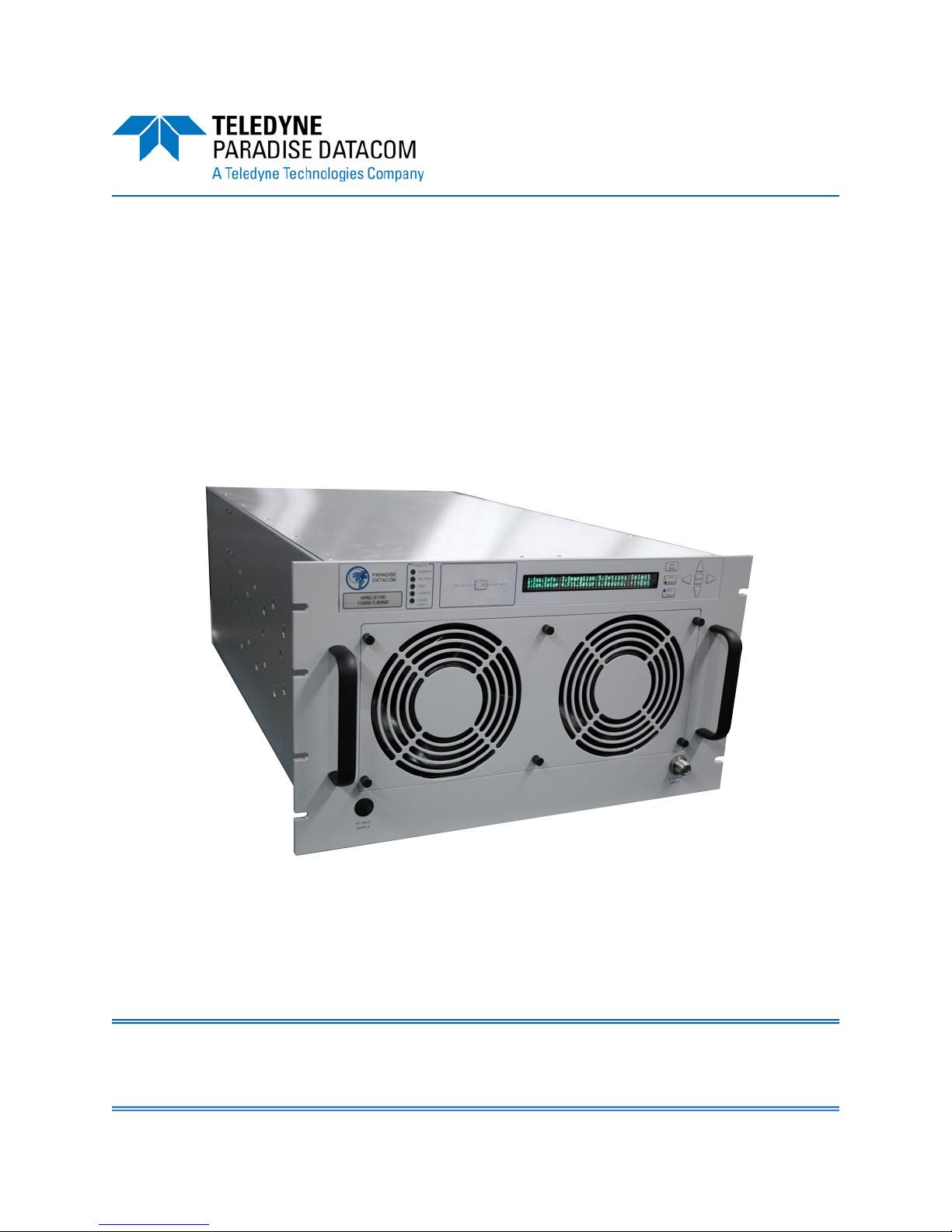
1.1 Description
The indoor rack mounted unit contains an internal microprocessor which allows for full
monitoring and control from the front panel’s 2x40 Vacuum Florescent Display and
pushbuttons, or via a remote serial (RS-232 or RS-485) or parallel connector. The
microprocessor monitors various voltages, currents and temperatures within the unit
for a full fault analysis. The user also has the ability to select additional faults related to
the RF output level, an optional reflected power level and operating temperature.
An internal attenuator allows up to 20.0 dB of attenuation to be applied to the RF
signal. Temperature compensation limits the amplifier’s output response from varying
significantly over the operating temperature. Also, the system contains input and
output sample ports.
Figure 1-1: Ku-Band Solid State Power Amplifier Chassis
6 RU SSPA Chassis Operations Manual 202058 REV AA 11

1.2 Specifications
Refer to the specification sheet in Appendix E for complete specifications.
1.3 Equipment Supplied
The following equipment is supplied with each unit:
• High Power SSPA Chassis RM (6 RU high)
• Power Supply Chassis (1 RU high) (standard)
• Rack Slides
• Interconnecting Cables between SSPA and Power Supply
• Operations Manual, High Power SSPA Chassis [202058]
1.4 Inspection
When the unit is received, an initial inspection should be completed. First ensure that
the shipping container is not damaged. If it is, have a representative from the shipping
company present when the container is opened. Perform a visual inspection of the
equipment to make sure that all items on the packing list are enclosed. If any damage
has occurred or if items are missing, contact:
Teledyne Paradise Datacom
328 Innovation Blvd., Suite 100
State College, PA 16803 USA
Phone: +1 (814) 238-3450
Fax: +1 (814) 238-3829
1.5 Rack Mounting
The SSPA Chassis is designed to fit in a standard 19” wide EIA rack. The unit is 6 rack
units or 10.47 inches (266 mm) high by 33.75 inches (857.3 mm) deep (including
connectors and bus bar). The power supply chassis is 1 rack units or 1.75 inches
(133.4 mm) high by 20.42 inches (518.7 mm) deep.
1.6 Shipment
To protect the SSPA Chassis during shipment, use high quality commercial packing
methods. When possible, use the original shipping container and its materials. Reliable
commercial packing and shipping companies have facilities and materials to adequately repack the instrument.
12 202058 REV AA 6 RU SSPA Chassis Operations Manual

1.7 Safety Considerations
Potential safety hazards exist unless proper precautions are observed when working
with this unit. To ensure safe operation, users must follow the information, cautions
and warnings provided in the manual, and the warning labels placed on the unit itself.
1.7.1 High Voltage Hazards
High Voltage for the purpose of this section is any voltage in excess of 30 volts. Voltages above this value can be hazardous and even lethal under certain circumstances.
Care should be taken when working with devices that operate at high voltage.
• All probes and tools that contact the equipment
should be properly insulated to prevent the operator from coming in contact with the voltage.
• The work area should be secure and free from nonessential items.
• Operators should never work alone on high voltage
devices. There should always be another person
present in the same work area to assist in the
event of an emergency.
• Operators should be familiar with procedures to employ in the event of an
emergency, i.e., remove all power, CPR, etc.
An AC powered unit will have 115 VAC or 230 VAC entering through the AC power
connector. Caution is required when working near this connector, the AC circuit breaker, or the internal power supply.
1.7.2 High Current Hazards
Many high power devices are capable of producing large
surges of current. This is true at all voltages, but needs to
be emphasized for low voltage devices. Low voltage
devices provide security from high voltage hazards, but
also require higher current to provide the same power.
High current can cause severe injury from burns and
explosion. The following precautions should be taken on
devices capable of discharging high current:
• Remove all conductive personal items (rings, watches, medals, etc.)
• The work area should be secure and free of non-essential items.
• Wear safety glasses and protective clothing.
• Operators should never work alone on high risk devices. There should
always be another person present in the same work area to assist in the
event of an emergency.
6 RU SSPA Chassis Operations Manual 202058 REV AA 13
• Operators should be familiar with procedures to employ in the event of an
emergency, i.e., remove all power, CPR, etc.
Large DC currents are generated to operate the RF Module inside of the enclosure.
EXTREME CAUTION IS REQUIRED WHEN THE ENCLOSURE IS OPEN AND THE
AMPLIFIER IS OPERATING. DO NOT TOUCH ANY OF THE CONNECTIONS ON
THE RF MODULES WHEN THE AMPLIFIER IS OPERATING. CURRENTS IN EXCESS OF 60 AMPERES MAY EXIST ON ANY ONE CONNECTOR.
1.7.3 RF Transmission Hazards
RF transmissions at high power levels may cause eyesight damage and skin burns.
Prolonged exposure to high levels of RF energy has been linked to a variety of health
issues. Please use the following precautions with high levels of RF power.
• Always terminate the RF input and output connector prior to applying prime AC input power.
• Never look directly into the RF output waveguide
• Maintain a suitable distance from the source of the
transmission such that the power density is below
recommended guidelines in ANSI/IEEE C95.1. The
power density specified in ANSI/IEEE C95.1-1992
is 10 mW/cm2. These requirements adhere to
OSHA Standard 1910.97.
When a safe distance is not practical, RF shielding should be used to achieve the recommended power density levels.
1.7.4 Electrical Discharge Hazards
An electric spark can not only create ESD reliability problems, it can also cause serious safety hazards. The following precautions should be followed when there is a risk
of electrical discharge:
• Follow all ESD guidelines
• Remove all flammable material from the area.
• All probes and tools that contact the equipment
should be properly insulated to prevent electrical discharge.
• The work area should be secure and free from non-essential items.
• Operators should never work alone on hazardous equipment. There
should always be another person present in the same work area to assist
in the event of an emergency.
• Operators should be familiar with procedures to employ in the event of an
emergency, i.e., remove all power, CPR, etc.
14 202058 REV AA 6 RU SSPA Chassis Operations Manual
Section 2: Operation of Stand-Alone Unit
2.0 Introduction
This section contains operating information including a description of the front panel
indicators and controls, and I/O connectors and their functions.
2.1 Description of SSPA Controls, Indicators and Connectors
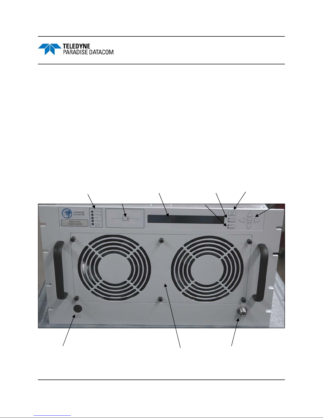
2.1.1 Front Panel Features
The 6RU RM SSPA has 10 LEDs to indicate the internal state of the amplifier. Five
fault condition LEDs on the left side of the front panel reflect some of the HPA major
faults plus the summary fault state. The SSPA online LED will turn green when the
amplifier is in Online mode (1:1 Mode) or serves as an AC power indicator in
standalone mode. Local/Remote and Mute/Unmute LEDs show the current control
mode and mute state of the HPA. Figure 2-1 illustrates the front panel.
Fault Condition LEDs
Standby Select key
40x2 VFD Local/Remote key
Mute/Unmute key
Main Menu key
Navigation keys
RF Input Sample Port (optional)
Figure 2-1: Front Panel, 6RU SSPA Chassis
6 RU SSPA Chassis Operations Manual 202058 REV AA 15
Removable Fan Tray
RF Output Sample Port

2.1.1.1 Vacuum Florescent Display (VFD)
The front panel 40x2 character VFD allows the user to get detailed information about
the state of the HPA and provides easy customization of operation through an
interactive menu structure. The menu structure is shown in Figure 2-11.
2.1.1.2 Navigation Keys
Up, Down, Left, Right and Enter keys on the right side of the front panel allow menu
navigation.
2.1.1.3 Standby Select Key
Function only in 1:1 Redundancy mode. Pressing this key will put the designated HPA
on standby. The LED beside this key will turn on when the HPA is online. This key has
no effect in either Standalone mode or the standby HPA in 1:1 Mode.
2.1.1.4 Main Menu Key
Provides a shortcut to the SSPA Main Menu.
2.1.1.5 Local / Remote Key
Allows the user to disable or enable the local control keypad console. If the SSPA is in
“Remote Only” mode, the unit will not react on any keystrokes except the “Local /
Remote” key.
2.1.1.6 Mute / Unmute Key
Provides an easy way to change the Mute status of the SSPA. Muting the amplifier via
the front panel requires 100 msec maximum (50 msec typical).
2.1.1.7 Input Sample Port (Optional)
An optional RF input sample port is located on the lower left corner of the SSPA front
panel. This provides a -10 dBc coupled sample of the RF input signal. It is a type N
female connector.
2.1.1.8 Output Sample Port
The Output RF Sample Port connector is located on the right lower corner of the HPA
front panel. This port provides a coupled sample of the RF output signal. A label listing
the calibration offset values is located below the type N female connector.
16 202058 REV AA 6 RU SSPA Chassis Operations Manual
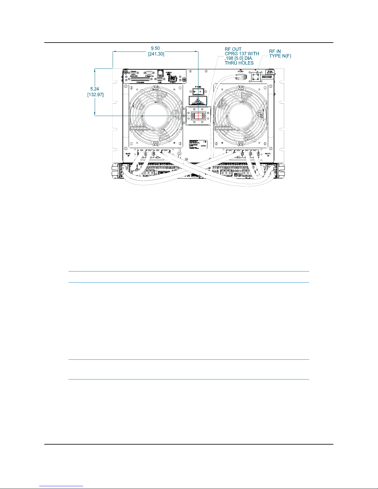
Figure 2-2: 6 RU SSPA Chassis Rear Panel
2.1.2 Rear Panel Features
Figure 2-2 shows a typical outline drawing of the rear panel view.
2.1.2.1 RF Input Port (J1) [Type N(F)]
The type N female connector on the right side of the rear panel is used for RF input.
Note: Maximum RF Input Power of +15 dBm.
2.1.2.2 RF Output Port (J2)
The waveguide in the middle of the rear panel is the conduit for the RF Output. C-Band
amplifiers use WR137 waveguide with CPRG137 flange, while Ku-Band amplifiers use
WR75 waveguide with grooved (PBR-120) flange. X-Band units employ WR112 rigid
waveguide with CPRG112 flange.
Warning! Do not operate the amplifier without having a termination
or mating connection at the RF Output. RF Hazard warnings apply.
2.1.2.3 Switch Port (J3) [Molex 43810-0002]
A 6-pin Molex connector header with blind insertion system guides (mates with Molex
P/N 39-01-2060) is used in a 1:1 Redundancy System to provide switching for the
waveguide transfer switch (RF Switch). Table 2-1 shows the pin-outs for the Switch
Port (J3).
6 RU SSPA Chassis Operations Manual 202058 REV AA 17
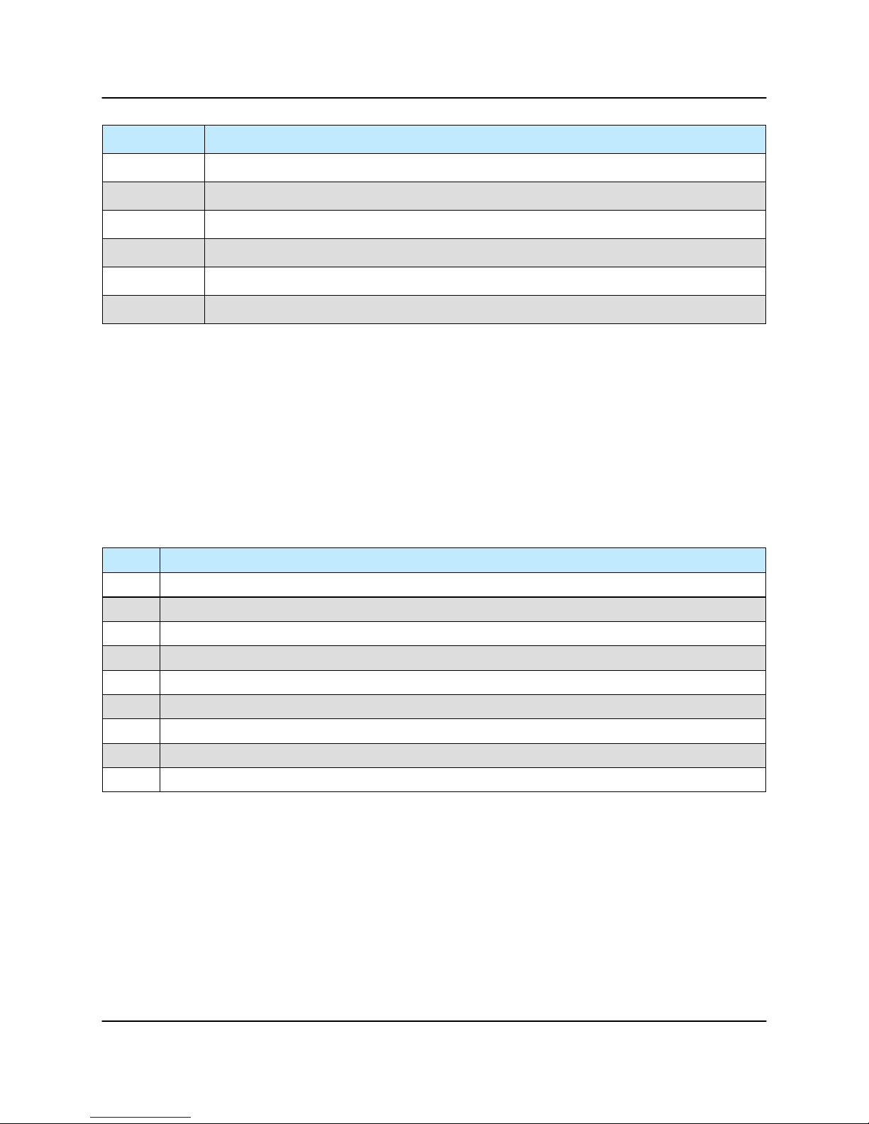
Table 2-1: Switch Port (J3) pin outs
Pin # Function / Description
1 +28V Switch Drive Output. 3 Amp over current protection.
2 Switch 1 Position 2 drive
3 Switch 1 Position 1 drive
4 +28V Switch Drive Output. 3 Amp over current protection.
5 Switch 2 Position 2 drive
6 Switch 2 Position 1 drive
2.1.2.4 Serial Main (J4) [DB9(F)]
A DB9 female connector serves as primary control interface connector. The interface is
re-configurable through the front panel or can be used as a RS-232 or R-485 interface
(2 or 4 wires). The RS-485 TX and RX pairs must be twisted for maximum transmission distance. A user-configurable 120-ohm termination resistor is provided on the
same connector. Table 2-2 shows the pin outs for the Serial Main (J4) connector. A
form C summary alarm is also present on J4. It is noted as a service request and
occupies pins 6, 7 and 8.
Table 2-2: Serial Main (J4) pin outs
Pin # Function / Description
1 RS485 TX+ (HPA Transmit +)
2 RS485 TX- (HPA Transmit -)/RS232 TX
3 RS485 RX- (HPA Receive -)/RS 232 RX
4 RS485 RX+ (HPA Receive +)
5 GND
6 Service Request 1 Form C relay NC contact (Closed on HPA Summary Fault)
7 Service Request Common Form C relay common contact
8 Service Request 2 Form C relay NO contact (Opened on HPA Summary Fault)
9 120 ohm termination (must be connected to pin 4 to enable termination)
2.1.2.5 Serial Local (J5) [DB9(M)]
This DB9 male connector is used in advanced system integration and for system
debugging purposes. Leave unconnected unless specified otherwise.
2.1.2.6 Service Port (J6) [Mini USB]
A 5-contact Mini USB male connector is used to provide field flash re-programmability
for the HPA controller card. In order to reload controller board firmware, connect this
port to a PC Parallel port using a straight through cable. See Section 3.1.3.
18 202058 REV AA 6 RU SSPA Chassis Operations Manual

2.1.2.7 Parallel I/O Port (J7) [DB37(F)]
A DB37 female type connector, the Parallel I/O Port contains a series of contact
closures for monitoring HPA faults as well as opto-isolated inputs for controlling some
HPA functions. Inputs react on the closure to ground. The minimal closure time is 50
mS. See Table 2-3 for a description of the pin outs for this connector.
Table 2-3: Parallel Connector (37 socket D connector)
Pin # Function / Description
1 Closed on Power Supply Fault Form C relay NC
2 Open on Power Supply Fault Form C relay NO
20 Power Supply Fault Common
21
22
3 Auxiliary Fault\Auto-Manual Common
4 Open on Mute. Form C Relay NC
5 Closed on Mute. Form C Relay NO
23 Mute Status Common
24 Closed on BUC Fault. Form C Relay NC
25 Open on BUC Fault. Form C Relay NO
6 BUC Fault Common
7 Closed on High Temperature Fault. Form C Relay NC
8 Open on High Temperature Fault. Form C Relay NO
26 High Temperature Fault Common
27
28
9 Regulator Low Voltage Fault\Standby-Online Common
10 Closed on DC Current Low Fault. Form C Relay NC
11 Open on DC Current Low Fault. Form C Relay NO
29 DC Current Low Fault Common
30 Closed on Low Forward RF Fault. Form C Relay NC
31 Open on Low Forward RF Form C Relay NO
12 Low Forward RF Fault Common
16 Auto/Manual toggle input. 50mS Closure to isolated ground to activate
17 Mute/Unmute toggle input. 50mS Closure to isolated ground to activate
18
35 HPA Standby input. 50mS Closure to isolated ground to activate
36 Local/Remote toggle. 50mS Closure to isolated ground to activate
37 Fault clear. 50mS Closure to isolated ground to activate
19 Isolated Signal Ground
15 +5V Isolated Power 20 mA
13, 32 +28V Auxiliary Power 1A
14, 33 Chassis Ground
1. Standalone mode. Closed on Auxiliary Fault;
2. 1:1 Redundancy Mode. Closed on Automatic switchover mode. Form C relay NC
1. Standalone Mode. Open on Auxiliary Fault;
2. 1:1 Redundancy Mode. Closed on Manual switchover mode. Form C relay NO
1. Standalone mode. Closed on Regulator Low Voltage Fault;
2. 1:1 Redundancy Mode. Closed on HPA Standby. Form C relay NC
1. Standalone Mode. Open on Regulator Low Voltage Fault.;
2. 1:1 Redundancy Mode. Closed on HPA Online Mode. Form C relay NO
Auxiliary Fault & Auxiliary Mute Input (See Section 2.1.2.7.1). 50 ms min.
6 RU SSPA Chassis Operations Manual 202058 REV AA 19
2.1.2.7.1 Hardware Mute (Tx Enable)
There are three ways to mute the amplifier via hardware input:
1. A 50 ms closure to ground on Port J7, Pin 17 toggles between Mute/Unmute
states;
2. Press the Main Menu key; select 4.Fault Setup and press the Enter key;
select 2.Auxiliary Faults and press the Enter key; select 1.Action and
press the Enter key; select 4.Alert+Mute and press the Enter key. Select
4.Fault Setup and press the Enter key; select 2.Auxiliary Faults and press
the Enter key; select 2.Fault Logic and press the Enter key; select 2.Fault
on Low and press the Enter key. A continuous closure to ground on Port J7,
Pin 18 will then mute the amplifier. See Section 2.3.4.2;
3. Press the Main Menu key; select 4.Fault Setup and press the Enter key;
select 2.Auxiliary Faults and press the Enter key; select 1.Action and
press the Enter key; select 4.Alert+Mute and press the Enter key. Select
4.Fault Setup and press the Enter key; select 2.Auxiliary Faults and press
the Enter key; select 2.Fault Logic and press the Enter key; select 2.Fault
on High. A continuous open to ground on Port J7, Pin 18 will mute the amplifier. See Section 2.3.4.2.
2.1.2.8 Link Port (J8) [DB9(F)]
The 9-pin male connector J8 Link Port is used to link a SSPA with other units in a
redundant system in order to pass online/standby status information between them.
Leave unconnected unless specified otherwise. This connector is discussed further in
Section 5.1.4 and Section 6.5.
2.1.2.9 Ethernet Port (J9) [RJ45]
This is a RJ45 connector with integrated magnetics and LEDs. This port becomes the
primary remote control interface when the Interface option is selected to “IPNet” as
described in Section 9.8. This feature allows the user to connect the SSPA to a
10/100 Base-T Local Area Network and have full-featured Monitor & Control functions
through a web interface. See Table 2-4 for Ethernet pin outs.
Table 2-4: Ethernet Port (J9) pin outs
20 202058 REV AA 6 RU SSPA Chassis Operations Manual
Pin # Function / Description
1 TX+
2 TX-
3 RX+
6 RX-
4,5,7,8 GND

Note: IP address, Gateway address, Subnet mask, IP port and IP Lock
address needs to be properly selected prior to first use (see Appendix C
for details).
LED lamps on the connector indicate network status. A steady Green light indicates a
valid Ethernet link; a Yellow LED flashes during any data transfer activity (on both
Transmit and Receive paths).
2.1.2.10 Power Supply M&C (J12)
The DB9 connector is connected to the 1RU power supply chassis. The SSPA
monitors the status of the power supply chassis and alarms in the event of a power
supply module failure. Due to the nature of the N+1 redundant power supply, a failure
will not take the amplifier off the air.
2.1.2.11 Power Switch
The power switch is located near the top center of the rear panel, above the RF Output
port (J2).
2.2 Redundant Power Supply Chassis
Prime power is provided to the 6RU RM SSPA via a 1RU power supply chassis, which
is configured with a parallel set of four (4) 2,500 W modules. All of the modules are
active and share the load current supplied to the amplifier. The power supply module
current capacity is chosen such that at least one extra module is included over the
amplifier’s current requirement. This is to say that the power supply is n+1 redundant.
The amplifier will continue to operate normally in the presence of one power supply
module failure.
The power supply modules are all hot swappable from the front panel. Therefore, if
there ever is a power supply module failure, there is no need to remove the entire
power supply chassis. The failed module is simply removed via the front panel as
shown in Figure 2-3.
Figure 2-3: Removing Power Supply Module from Bay
6 RU SSPA Chassis Operations Manual 202058 REV AA 21
The power supply module removal can be performed with the system powered. This is
to say that the modules are “hot swappable”.
In keeping with the redundant architecture of the power supply, there are individual AC
inputs for each power supply module. DC Outputs are in a bus bar configuration. See
Figure 2-4.
+ -
DC Outputs
+ -
DC Outputs
Figure 2-4: 1RU Power Supply AC Line Inputs/Outputs
The standard 24V AC input configuration for the 2.5 kW power supply is 100-240 VAC
single phase, 47-63 Hz, 0.99 power factor per module. A separate AC input transformer could feed each AC input.
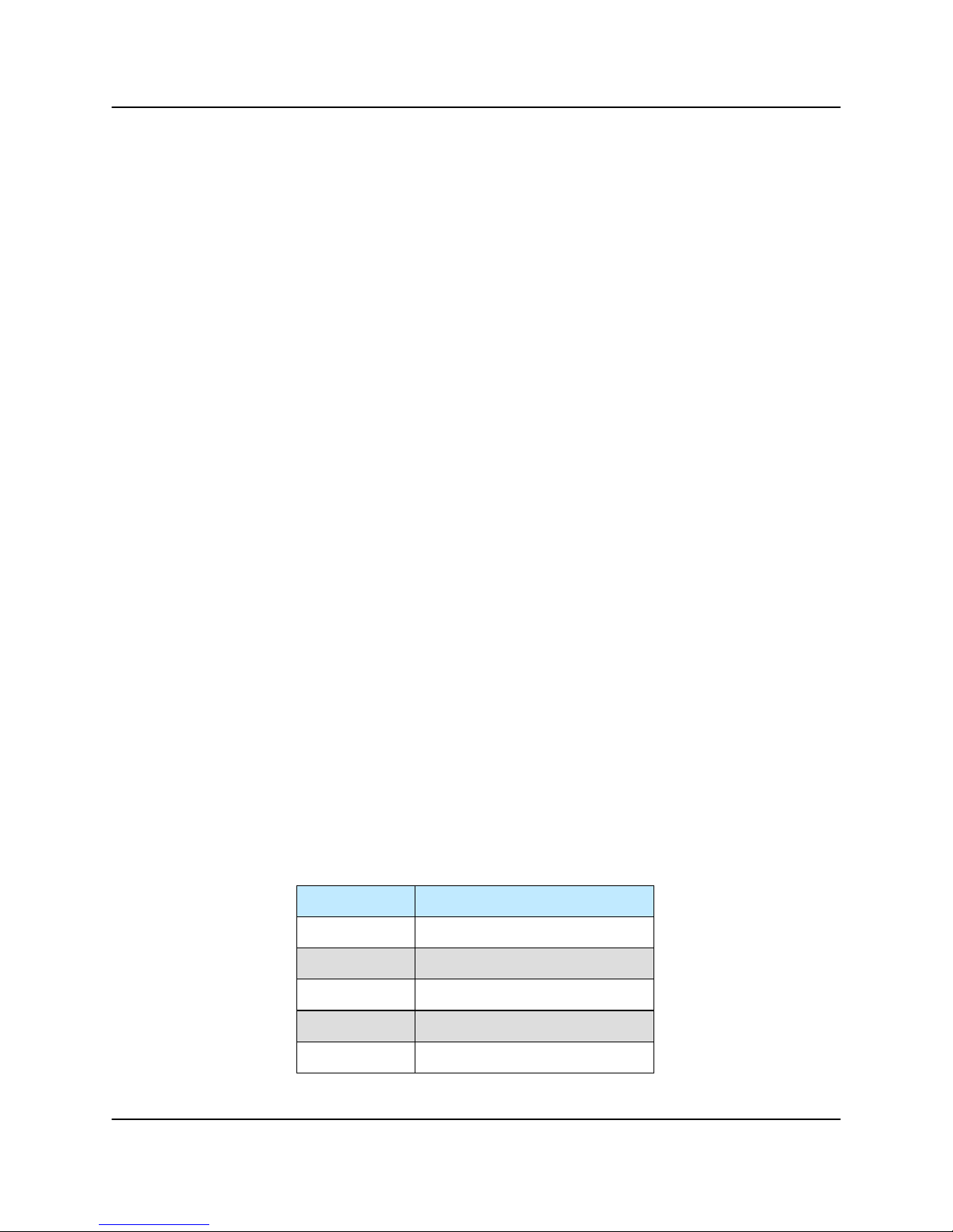
The DC output from each power supply is connected to the SSPA via four (4) sets of
2AWG cables. These cables are bolted to the bus bars of the power supply, as shown
in Figure 2-5.
Figure 2-5: Connect Cables to DC Output Bus Bar
Connect the mating DC output cable quick-disconnect connectors to the positive and
negative power connecters at the rear of the SSPA chassis. See Figure 2-6.
22 202058 REV AA 6 RU SSPA Chassis Operations Manual
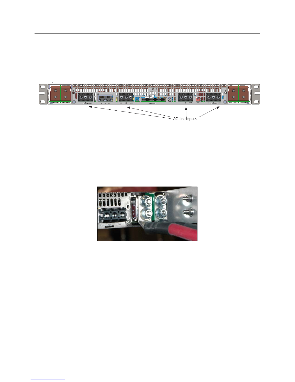
2.2.1 AC Mains Connection
The AC mains connection to the power supply chassis is provided by a terminal block
connection for each power supply module in the chassis. See Figure 2-6.
Figure 2-6: Power Supply AC Input Wiring
Connect your first line/hot to L1, your second line or neutral to L2/N, and finally your
AC ground to GRD. Tighten screws to 6 in-lbs. The connection identification is given
below:
• Chassis Earth - Green/Yellow
• Line - Brown
• Neutral - Blue
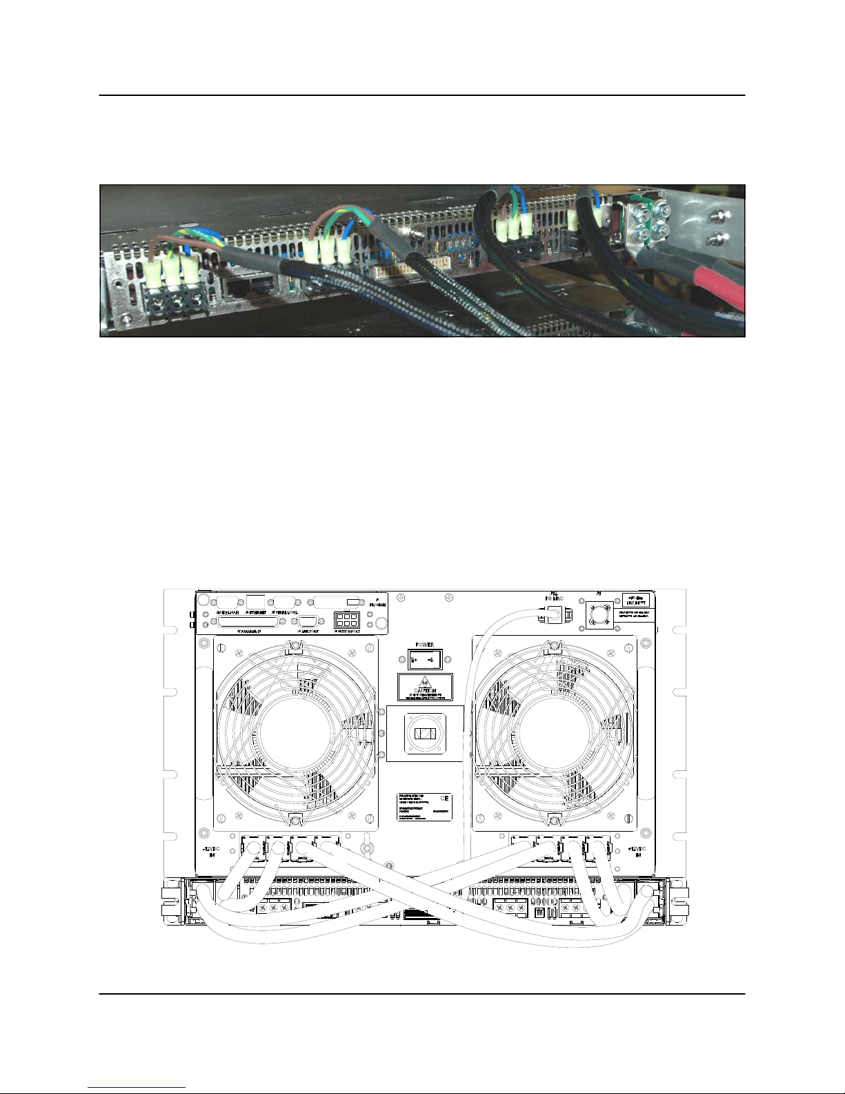
2.2.2 DC Output Connection
The power supply has two sets of DC output cabling. The lug connections should be
connected as shown in Figure 2-7.
6 RU SSPA Chassis Operations Manual 202058 REV AA 23
Figure 2-7: DC Output Cabling
The DC connections from the power supply are made by an in-line threaded terminal
connection. Verify the polarity of connections before powering units on. Outputs are
labeled "+" for positive and "-" for negative. A DC reference ground should be connected to the appropriate output for desired polarity of the system. It is important to make
sure that these connections are kept very tight (65 in/lbs recommended torque) for
minimum contact resistance.
2.2.3 Power Supply Module Alarm Connection
The power supply module has an alarm output. The power supply alarms are monitored by the SSPA Chassis monitor and control system. This system provides local
and remote alarm reporting in the event of a power supply module failure.
The module alarms are open-collector signals with a high impedance state = fault logic
level. Under normal operation, the alarm outputs are in an open collector logic low
state.
2.2.4 Alarm Configuration at the SSPA Chassis
The power supply alarms may be monitored via the SSPA Chassis front panel menu.
See Section 2.3.1.2. In the event that one or more power supply modules enter a fault
condition, the SSPA Chassis will report a major (Summary) fault and will mute until the
fault conditions are cleared.
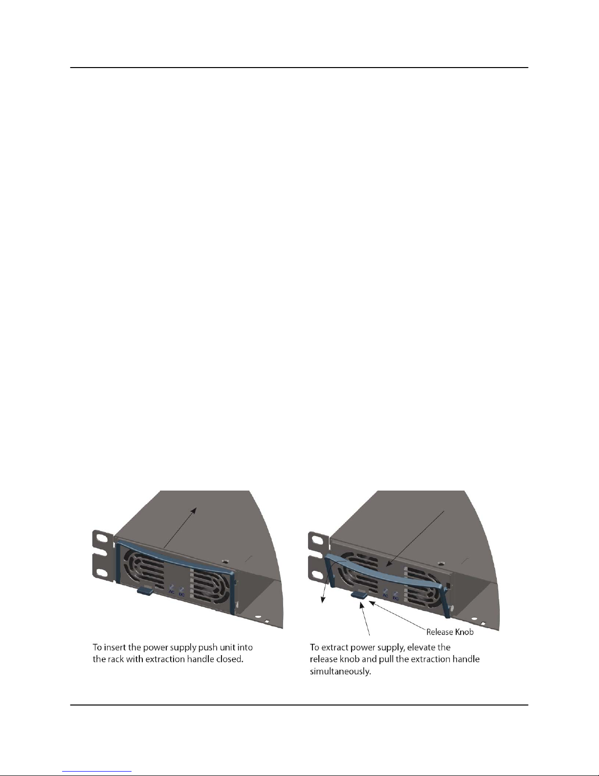
2.2.5 Power Supply Removal/Replacement
To remove a failed module, simply lift the release knob and pull the extraction handle
until the module slides from the shelf. Slide the replacement module into the empty slot
until the module is flush with the front of the shelf. See Figure 2-8.
Figure 2-8: 1RU Power Supply Module Insertion/Extraction
24 202058 REV AA 6 RU SSPA Chassis Operations Manual
2.3 Menus
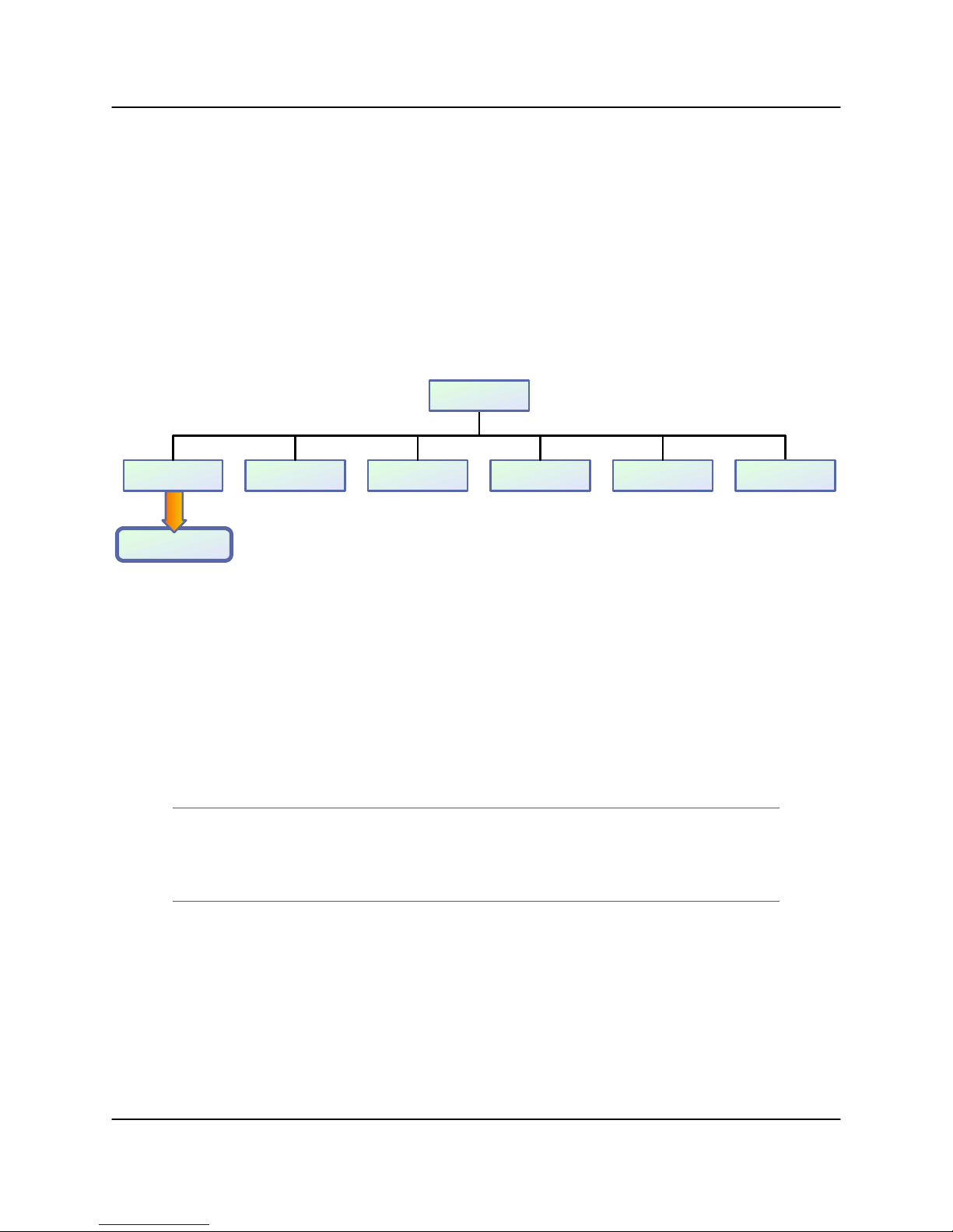
Figure 2-9 shows the Front Panel Display Menu Structure hierarchy. There are six
main levels of menu selections.
• Sys.Info - System Information menu sublevel (See Section 2.3.1)
• Com.Setup - Serial Communication related settings (See Section 2.3.2)
• Operation Setup - System operation related settings (See Section 2.3.3)
• Fault Monitoring Setup - Fault handling settings (See Section 2.3.4)
• Options - Backup/restore and password settings (See Section 2.3.5)
• Redundancy - Switching and standby settings (See Section 2.3.6)
Main Menu
2.Com Setup1.Sys Info 3.Operation 4.F l t. Se tu p 5.Options
To Sys Info Page 1
6.Redundancy
Figure 2-9: Front Panel Menu Structure
The menu tree is accessed by pressing the Main Menu key on the front panel of the
SSPA. Navigation through the menu structure is handled by using the Up Arrow [▲],
Down Arrow [▼], Left Arrow [◄], and Right Arrow [►] keys and the Enter key to
select from the items shown in the front panel display.
For menus where an actual numerical value must be entered, the Up Arrow [▲] and
Down Arrow [▼] keys change the number by factors of 10; the Left Arrow [◄] and
Right Arrow [►] keys change the number in increments of 1.
Note: If the Local/Remote key is toggled so that the Remote LED is illu-
minated, the Main Menu key, Arrow keys and Enter key are disabled. To
regain local control, press the Local/Remote key so that the Local LED is
illuminated.
6 RU SSPA Chassis Operations Manual 202058 REV AA 25
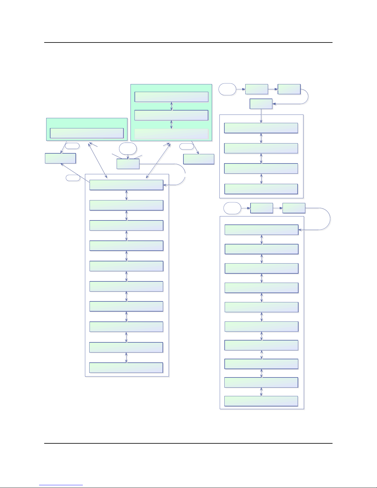
2.3.1 System Information Sub-Menu
The informative sub-level menu structure contains several pages, as shown in Figure
2-10.
Main
Menu
IPAddr:XXX.XXX.XXX.XXX M AC:XXXXXXXXXX
Web Pas s word :XXXXXXXXXXXXXXXXXXXXX
TrapNMSIP: XXX.XXX.XXX.XXX
2.Com Setup 5.IPSetup
1.IPInfo
IP Setup Menus
Subn et:XXX.XXX.XXX.XXX Port:XXXXX
Gateway :XXX.XXX.XXX.XXX
LockIP:XXX.XXX.XXX.XXX
Community Get:XXXXXXXXXXXXXXXXXXXXX
Community Set:XXXXXXXXXXXXXXXXXXXXX
Unit operation under system control
Enter
1.Clear Faults
2.Back
Enter
N+1 Slave unit system info
N+1 Slave Unit
S
l
a
Atten.(dB):XX.X FrwrdRF(dBm):XX.X
Alarms:XXXXXX Ref.RF(dBm):XX.X
v
e
U
System Info Menus
Main
Menu
n
i
t
s
1.Sys.Info
N+1 Master unit system info
Cabinet Temp(C):XXX N+1Stbys::XXXXXX
Cabinet Fan:XXXXXX
N+1 Arr.Size:XXX N+1 Alarms:XXXXXX
N+1 Address :XXX N+1 State:XXXXXX
Atten.(dB):XX.X SysRFOut(dBm):XX.X
AutoGain(dB):XX.X Ref.RF(dBm):XX.X
y
l
n
o
t
i
n
U
r
e
t
s
a
M
Enter
1.Clear Faults
2.Back
Non N+1 Un its
PS:XXXXXX Low RF:XXXXXX Fan:XXXXXX
AU X:XXXXXX VSWR:XXXXXX BU C :XXXXXX
RFSW1:XXXXXX State:XXXXXX Prior:XXXX
RFSW2:XXXXXX Mute:XXXXXX P olSel:XXXX
Prtc l:XXXXXX Intrf c:XXXXX Buzzer:XXX
Baud:XXXXX Addrs. :XXX Latch:XXX
Mode:XXXXXXX Ctrl:XXXXXX Unit:XXXX
Stby:XXXX Switch:XXXXX FSpeed:XXX
PS1(V):XX.X Boost1(V):XX.X DC(A):XX.X
PS2(V):XX.X Boost2(V):XX.X
Regulator:XXXXXX Temperatu r e:XXXXXX
DCCurrent:XXXXXX Temp. ( C):XXX
Mod1:XXXXX Mod3:XXXXX PreAmp:XXXXX
Mod2:XXXXX Mod4:XXXXX PSModFl ts:XXX
Chssy Temp(C):XXX BUC PS1(V):XX.X
RecordHigh(C):XXX BUC PS2(V): XX.X
MuteFault:XXXXX LastFault:XXXXX
MFaultCause:XXXXX MasterN1IP:XXX
Main
Menu
Digic o r e X Ve rsio n X. X X ( XX ) Bui l t YYYY.MM. D D
SSPAID:XXXXXXXXXXXXXXXXXXXX
UserInfo:XXXXXXXXXXXXXXXXXXXX
Firmware:XXXXXXXXXX Module1
ID:XXXXXXXXXXXXXXXXXXXXXX
Firmware:XXXXXXXXXX Module2
ID:XXXXXXXXXXXXXXXXXXXXXX
Firmware:XXXXXXXXXX Module3
ID:XXXXXXXXXXXXXXXXXXXXXX
Firmware:XXXXXXXXXX Module4
ID:XXXXXXXXXXXXXXXXXXXXXX
Firmware:XXXXXXXXXX PreAmp
ID:XXXXXXXXXXXXXXXXXXXXXX
PSType:XXX DigicoreID:XXX
I/OBoardID:XXX
Current Date/Time:
YY/MM/DD HH:MM:SS
3.Operation
SSPA Firmware Info
Teledyne ParadiseDatacom LLC
1.Info
Figure 2-10: System Information Menu Structure
26 202058 REV AA 6 RU SSPA Chassis Operations Manual
HPA R u n T im e:
Days :DDDD Hrs :HH Min :M M Sec :SS

The user can also browse among these pages by navigating the cursor around the
menu fields and pressing the Enter button on the keypad. Note that this function will
not work if the “Fault Latch” option is selected.
In a N+1 configuration, the Master unit default System Information page is as
described in Section 2.3.1.16; the default page for Slave units is as described in
Section 2.3.1.17. In non-N+1 configurations, the default page is as described in Section 2.3.1.1.
2.3.1.1 Sys Info Page 1
This is the HPA main status information page. The page shows:
• Atten.(dB) — HPA attenuation measured in dB, with accuracy of 0.1 dB;
• FrwrdRF(###) — Forward RF Power, measured in either dBm with reso-
lution of 0.1 dBm, or Watts with a resolution of 0.1 Watts, with a 20 dBm
dynamic range from the maximum rated output power;
• Alarms — Will display “FAULT!” if a fault is present on the HPA, or
“None” if no fault is present.
• Ref.RF(###) — Reflected RF Power, measured in either dB with resolu-
tion of 0.1 dBm, or Watts with a resolution of 0.1 Watts. Displays “N/A” if
unavailable. See Section 2.6 for further discussion.
When on this page, pressing the Enter key will open the Clear Faults Menu. The Clear
Faults Menu is also available from the N+1 Master Page 1 and N+1 Slave Info Page.
2.3.1.1.1 Clear Faults Menu
This page allows user to clear latched faults conditions, if the Fault Latch option is enabled.
• 1.Clear Faults — When selected, all latched fault conditions are cleared.
Also Master N+1 unit fault history and SNMP trap history will be cleared
when “Clear Faults” function is selected.
• 2.Back — When selected, navigates back to System Info page without
clearing fault state holders.
6 RU SSPA Chassis Operations Manual 202058 REV AA 27

2.3.1.2 Sys Info Page 2
This page shows a variety of alarm states which may be present within the HPA. Fault
values could be “FAULT!”, “Normal” and “N/A”. If the fault condition doesn't apply to the
HPA it will display “N/A” for “Not Available”.
• PS — Power supply alarm, displays “Normal” if HPA power supplies are
normally operational and “FAULT!” if one or more power supplies failed.
• FwdRF — Depending on setting, either Low RF fault, High RF fault or
ALC fault. See Section 2.3.4.5;
• Fan — Cooling system failures;
• Aux. — Auxiliary fault condition;
• VSWR — High Reflected power fault;
• BUC — Block Up converter fault.
2.3.1.3 Sys Info Page 3
This page displays miscellaneous information related to the redundancy operation and
the HPA mute status.
• RFSW1 — Displays the state of RF switch 1, possible values - “Pos1”,
“Pos2”, “N/A”, “FAULT!”;
• RFSW2 — Displays the state of RF switch 2, possible values - “Pos1”,
“Pos2”, “N/A”, “FAULT!”;
• State — HPA online state, possible values “Online”, “Standby”;
• Mute — HPA mute state, possible values “Clear”, “Set”;
• Prior — Priority polarization select (1:2 Mode Only);
• PolSel — Current Polarization output (1:2 Mode Only)
2.3.1.4 Sys Info Page 4
This page displays various HPA settings:
• Prtcl. — Current HPA remote control protocol. Will display “Terminal”, if
terminal mode protocol is currently active and “Normal” if string I/O type
protocol is used.
• Baud — Selected baud rate for remote control serial port. Selection:
“2400”, “4800”, “9600”, “19200”, “38400”;
• Intrfc. — Selected serial port interface. Selection: “RS232”, “RS485”.
• Addrs. — HPA remote control network address. Value could be in range
from 0 to 254. Note: address 255 is reserved for global calls and should
not be used for an individual unit’s addressing.
• Buzzer — Audible alarm availability. “Dis” for disabled; “Enb” for enabled.
• Latch — Fault latch option selection. “Dis” for disabled; “Enb” for ena-
bled.
28 202058 REV AA 6 RU SSPA Chassis Operations Manual

2.3.1.5 Sys Info Page 5
Page 5 shows settings related to the HPA 1:1 Redundant System operation.
• Mode — Indicates HPA operational mode. See Section 2.3.3.4.
• Stby. — Shows the HPA standby state selection. “Hot” - Hot standby op-
eration (HPA retains unmuted state during standby); “Cold” - Cold
standby (HPA always mutes itself in standby mode and unmutes when
switched online).
• Ctrl. — Shows HPA control style. “Local” - Both local and remote control
are supported; “Remote” - When only remote control provided (keypad
locked);
• Switch — Indicates switching style. “Auto” - Automatic fault tracking/
switching; “Manual” - If redundancy switching is provided by the operator.
• Unit — Redundancy topological factor. “HPA1” - HPA connected to RF
switch port 1 or 4 (Online Position 1 of the RF switch); “HPA2” - HPA
connected to RF switch port 2 or 3 (Online Position 2 of the RF switch).
• FSpeed — Displays the current fan speed setting of “Hi”, “Low” or “Auto”.
2.3.1.6 Sys Info Page 6
This page shows the status of the HPA’s internal power supplies.
• PS1(V) — Main power supply 1 output voltage with resolution of 0.1V.
Normal output voltage for GaAs amplifiers is in the range of 11 to 13 V;
Normal output voltage for GaN amplifiers is in the range of 25 to 28 V.
• PS2(V) — Main power supply 2 output voltage.
• Boost1(V) — Booster power supply 1 output voltage with resolution of
0.1V. Normal range 24 to 30 V (typical 28V);
• Boost2(V) — Booster power supply 2 output voltage.
• DC (A) — Total DC current draw by RF modules from main power sup-
ply. Value varies depending on the power level of the HPA. If the HPA is
muted, current normally drops to within the 0 to 5 A range.
2.3.1.7 Sys Info Page 7
This page shows RF module related faults and conditions.
• Regulator — RF module regulator low voltage fault. Values: “FAULT!” or
“Normal”;
• DC Current — Low DC current fault. Values: “FAULT!” or “Normal”;
• Temperature — High temperature fault. Values: “FAULT!” or “Normal”.
• Temp.(C) — Internal RF module plate temperature in Celsius. In multi-
module units, only the hottest module baseplate temperature is displayed.
6 RU SSPA Chassis Operations Manual 202058 REV AA 29

2.3.1.8 Sys Info Page 8
This page shows individual RF module states in multi-module HPAs.
• Mod# & PreAmp — Mod1 to Mod4 represent the overall state of the rel-
evant RF Power modules. If the amplifier is equipped with a separate
-amplifier module, the “PreAmp” value will represent the overall state of
the pre-amplifier. Under normal operation, the value will read “Normal”.
If a unique module does not exist in the HPA configuration, the value
shows “N/A” (not available). Each value represents the summary fault
state of an individual RF module, which includes the Voltage, Current and
Temperature state as well as the quality of data connection with module.
For a module or pre-amp exhibiting a fault, the value will read “FAULT!”.
If the HPA controller card cannot reliably communicate with an SSPA
module, that module will be declared faulted. This type of fault will not affect the overall summary fault state, because the controller card has the
ability to track RF module faults independently. When an existing module
or pre-amp is present in the current HPA configuration, but fails to respond to control board status queries, “ComErr” (Communication Error)
will be displayed.
• PSModFlts — For amplifiers utilizing an external N+1 power supply, this
value indicates the number of detected N+1 PS module faults. For units
with an internal power supply, this value reads “000” and should be ignored. Check PS1 and PS2 Voltage readings to assess the state of an
internal power supply.
2.3.1.9 Sys Info Page 9 (version 6.00)
This page shows various miscellaneous operation parameters.
• Chssy Temp — Chassis temperature reading measured by the control
board. Since the control board is typically located at rear of the chassis,
this reading correlates with the exhaust air temperature;
• RecordHigh — The highest temperature detected over unit lifetime. This
value is updated each time a temperature higher than the current record
is detected. Value could be used for SSPAs problem troubleshooting.
Record data is factory reset only.
• BUC PS1(V) — This value represents the power supply voltage used for
biasing an optional BUC unit. Voltage could be used for detecting problems related to BUC operation. The SSPA does not have a specific alarm
threshold for this voltage. Normal reading for this parameter should be in
range of 15V– 16V.
• BUC PS2(V) — This value represents secondary BUC power supply volt-
ages. For a unit equipped with a single power supply this value shows “N/
A” (not available).
30 202058 REV AA 6 RU SSPA Chassis Operations Manual
 Loading...