

Page 1
Teledyne Analytical Instruments
OPERATING INSTRUCTIONS FOR
Model 6750
Total Organic Carbon Analyzer
DANGER
Toxic gases and or flammable liquids may be present in this monitoring system.
Personal protective equipment may be required when servicing this instrument.
Hazardous voltages exist on certain components internally which may persist
for a time even after the power is turned off and disconnected.
Only authorized personnel should conduct maintenance and/or servicing.
Before conducting any maintenance or servicing, consult with authorized
supervisor/manager.
P/N M
ECO:
Page 2

Model 6750
Teledyne Analytical Instruments ii
Copyright © 2005 Teledyne Instruments/ Analytical Instruments
All Rights Reserved. No part of this manual may be reproduced, transmitted, transcribed,
stored in a retrieval system, or translated into any other language or computer language in
whole or in part, in any form or by any means, whether it be electronic, mechanical,
magnetic, optical, manual, or otherwise, without the prior written consent of Teledyne
Instruments/ Analytical Instruments, 16830 Chestnut Street, City of Industry, CA 91749-
1580.
Warranty
This equipment is sold subject to the mutual agreement that it is warranted by us free from
defects of material and of construction, and that our liability shall be limited to replacing or
repairing at our factory (without charge, except for transportation), or at customer plant at
our option, any material or construction in which defects become apparent within one year
from the date of shipment, except in cases where quotations or acknowledgements provide
for a shorter period. Components manufactured by others bear the warranty of their
manufacturer. This warranty does not cover defects caused by wear, accident, misuse,
neglect or repairs other than those performed by TI/AI or an authorized service center. We
assume no liability for direct or indirect damages of any kind and the purchaser by the
acceptance of the equipment will assume all liability for any damage which may result from
its use or misuse.
We reserve the right to employ any suitable material in the manufacture of our apparatus,
and to make any alterations in the dimensions, shape or weight of any parts, in so far as
such alterations do not adversely affect our warranty.
Important Notice
This instrument provides measurement readings to its user, and serves as a tool by which
valuable data can be gathered. The information provided by the instrument may assist the user
in eliminating potential hazards caused by his process; however, it is essential that all
personnel involved in the use of the instrument or its interface, with the process being
measured, be properly trained in the process itself, as well as all instrumentation related to it.
The safety of personnel is ultimately the responsibility of those who control process
conditions. While this instrument may be able to provide early warning of imminent
danger, it has no control over process conditions, and it can be misused. In particular, any
alarm or control systems installed must be tested and understood, both as to how they
operate and as to how they can be defeated. Any safeguards required such as locks, labels,
or redundancy, must be provided by the user or specifically requested of TI/AI at the time
the order is placed.
Therefore, the purchaser must be aware of the hazardous process conditions. The purchaser
is responsible for the training of personnel, for providing hazard warning methods and
instrumentation per the appropriate standards, and for ensuring that hazard warning devices
and instrumentation are maintained and operated properly.
Teledyne Instruments/ Analytical Instruments, the manufacturer of this instrument, cannot
accept responsibility for conditions beyond its knowledge and control. No statement
expressed or implied by this document or any information disseminated by the
manufacturer or its agents, is to be construed as a warranty of adequate safety control under
the user’s process conditions.
Page 3

Total Organic Carbon Analyzer
Teledyne Analytical Instruments iii
Specific Model Information
Instrument Serial Number: _______________________
Instrument Range: _______________
Calibrated for: _______________
Background Gas: _______________
Zero Gas: _______________
Span Gas: _______________
Page 4
Model 6750
Teledyne Analytical Instruments iv
Safety Messages
Your safety and the safety of others is very important. We have
provided many important safety messages in this manual. Please read
these messages carefully.
A safety message alerts you to potential hazards that could hurt you
or others. Each safety message is associated with a safety alert symbol.
These symbols are found in the manual and inside the instrument. The
definition of these symbols is described below:
GENERAL WARNING/CAUTION: Refer to the
instructions for details on the specific danger. These cautions
warn of specific procedures which if not followed could cause
bodily Injury and/or damage the instrument.
CAUTION: HOT SURFACE WARNING: This warning is
specific to heated components within the instrument. Failure
to heed the warning could result in serious burns to skin and
underlying tissue.
WARNING: ELECTRICAL SHOCK HAZARD: Dangerous
voltages appear within this instrument. This warning is
specific to an electrical hazard existing at or nearby the
component or procedure under discussion. Failure to heed this
warning could result in injury and/or death from
electrocution.
Technician Symbol: All operations marked with this symbol
are to be performed by qualified maintenance personnel only.
NOTE: Additional information and comments regarding a
specific component or procedure are highlighted in the form
of a note.
CAUTION: THE ANALYZER SHOULD ONLY BE USED FOR THE
PURPOSE AND IN THE MANNER DESCRIBED IN
THIS MANUAL.
No
Symbol
Page 5

Total Organic Carbon Analyzer
Teledyne Analytical Instruments v
IF YOU USE THE ANALYZER IN A MANNER OTHER
THAN THAT FOR WHICH IT WAS INTENDED,
UNPREDICTABLE BEHAVIOR COULD RESULT
POSSIBLY ACCOMPANIED WITH HAZARDOUS
CONSEQUENCES.
This manual provides information designed to guide you through
the installation, calibration operation and maintenance of your new
analyzer. Please read this manual and keep it available.
Occasionally, some instruments are customized for a particular
application or features and/or options added per customer requests.
Please check the front of this manual for any additional information in
the form of an Addendum which discusses specific information,
procedures, cautions and warnings that may be peculiar to your
instrument.
Manuals do get lost. Additional manuals can be obtained from
TI/AI at the address given in the Appendix. Some of our manuals are
available in electronic form via the internet. Please visit our website at:
www.teledyne-ai.com.
Page 6

Model 6750
Teledyne Analytical Instruments vi
Table of Contents
List of Figures.............................................................................. ix
List of Tables ............................................................................... xi
Introduction .................................................................................. 1
1.1 Main Features of the Analyzer 1
1.2 Options 2
1.3 Typical Applications 2
1.4 Intended Use of the Analyzer 2
1.5 Operator Interface 3
Theory of Operation ..................................................................... 5
2.1 Overview 5
2.2 Background 5
2.3 The UV/Heated Persulfate Method of Analysis 9
2.4 Subsystems Principles of Operation 11
2.4.1 Sample Handling 11
2.4.1.1 Liquid Phase Sample Handling 11
2.4.2.2 Gas Phase Sample Handling 13
2.4.2 Inorganic Carbon Removal/Analysis 14
2.4.3 Oxidation 15
2.4.4 NDIR CO2 Gas Detection 17
2.4.5 Electronic Signal Processing, Display and Control 18
2.4.5.1 Benchmark/Auto-Validation 19
2.4.5.2 Auto-Calibration 19
2.4.5.3 Auto-Cleaning 19
Installation .................................................................................. 21
3.1 Unpacking the Analyzer 21
3.2 Mounting the Analyzer 21
Page 7

Total Organic Carbon Analyzer
Teledyne Analytical Instruments vii
3.3 Electrical Connections 23
3.3.1 Power Connection 23
3.3.2 Analog Outputs 24
3.3.3 Alarm Connections 25
3.3.4 RS-232 Serial Connection 25
3.4 Gas/liquid Connections 25
3.4.1 Liquid Connections 25
3.4.2 Gas Connections 26
3.5 Checking the System 27
Setup and Operation...................................................................29
4.1 Analyzer Startup 29
4.2 Menus 31
4.2.1 Run Mode 31
4.2.2 Parameter Menu 32
4.2.3 Alarm Settings 33
4.2.4 Stream Sequencer 34
4.2.5 D/DBPR 35
4.3 Detailed Calibration Procedures 36
4.4 Operation 40
4.5 Shutdown 41
4.6 Historical Data 41
Maintenance ................................................................................43
5.1 Compupter-aided Testing 43
5.2 Troubleshooting 44
5.3 Module Service 45
5.3.1 NDIR (Gas Calibration) 45
5.3.2 NDIR Service 47
5.3.3 Master Interface Board (P/N ST13042-1). 53
5.3.4 D. C. Power Supply 54
5.3.5 CE Computer (P/N 13039) 55
5.3.6 UV Lamp (P/N ST20009) 56
5.3.7 UV Reactor Assembly (P/N ST20003-1) 57
Page 8

Model 6750
Teledyne Analytical Instruments viii
5.3.8 UV Power Supply 58
5.3.9 Mass Flow Controller (P/N ST18001A) 59
5.3.10 Metering Valve (P/N ST16050) 60
5.3.11 Sparger (P/N ST20025) 61
5.3.12 Pumps 63
5.3.12.1 Pump Motor Replacement 63
5.3.12.2 Pump Head Tubing Replacement 65
5.3.13 4-20 mA Adjustment Procedure 67
5.3.13.1 Setting 100 mV Control Voltage 68
5.3.13.2 Setting of 4-20 mA output 68
Appendix..................................................................................... 69
A.1Specifications 69
A.2 Parts Listing 71
A.3 Options 76
A.3.1 Option 200008 76
A.3.2 Option 200009 76
A.3.3 Option 200010 76
A.3.4 Option 200016 77
A.3.5 Option 200017 77
A.3.6 Option 200009 77
A.3.7 Option 400008 77
A.3.8 Option 200026 77
A.4 AS-BUILT Drawings 79
Index............................................................................................ 81
Page 9

Total Organic Carbon Analyzer
Teledyne Analytical Instruments ix
List of Figures
Figure 1-1: The Model 6750 TOC Analyzer (Front door removed) . 3
Figure 2-1: NPOC or TOC – Direct Method.................................... 6
Figure 2-2: TOC – True Method ..................................................... 6
Figure: 2-3: TOC Measurement Basics .......................................... 8
Figure 2-4: UV/Persulfate Method .................................................. 8
Figure 2-5: Comparison of TOC Measurement Technologies........10
Figure 2-6: Sample Handling for TOC -Direct................................12
Figure 2-7: Sample Handling TOC-True........................................13
Figure 2-8: Relationship Between TIC and pH ..............................15
Figure 2-9: Oxidation Reactions....................................................16
Figure 2-10: Model 6750 NDIR Unit ..............................................17
Figure 3-1: Analyzer Dimensions ..................................................22
Figure 3-2: Required Door Clearance ...........................................22
Figure 3-3: Internal Components of the Model 6750 Analyzer.......23
Figure 3-4: Electrical Connections to the Model 6750 ...................24
Figure 3-5: Gas and Liquid Connections to the Analyzer...............26
Figure4-1: Drain Connections ......................................................30
Figure 4-2: Gas Liquid Separator D. I. Filling ................................31
Figure 4-3: The RUN Screen.........................................................40
Figure 5-1: Disconnecting Tubing from Reactor ............................46
Figure 5-2: IR Calibration Adapter P/N ST20026...........................46
Figure 5-3: Installing Calibration Adapter ......................................47
Figure 5-4: Removing the NDIR Unit P/N ST 36000......................48
Figure 5-5: Removing the Master Interface Board.........................53
Page 10

Model 6750
Teledyne Analytical Instruments x
Figure 5-6: DC Power Supply Module........................................... 54
Figure 5-7: Replacing CE Computer............................................. 55
Figure 5-8: UV Lamp Replacement .............................................. 56
Figure 5-9: Removing the UV Reactor Assembly.......................... 57
Figure 5-10: Removing the UV Power Supply............................... 59
Figure 5-11: Mass Flow Controller................................................ 60
Figure 5-12: Metering Valve ......................................................... 61
Figure 5-13: Sparger .................................................................... 62
Figure 5-14: Removing the Pump ................................................ 65
Figure 5-15: Pump Head Tubing Replacement............................. 67
Page 11

Total Organic Carbon Analyzer
Teledyne Analytical Instruments xi
List of Tables
Table 4-1: Preparation of Standards (TOC/TIC) ............................37
Table 5-1: Troubleshooting ...........................................................44
Page 12
Model 6750
Teledyne Analytical Instruments xii
DANGER
COMBUSTIBLE GAS USAGE
WARNING
This is a general purpose instrument designed for use in a
non-hazardous area. It is the customer's responsibility to
ensure safety especially when combustible gases are being
analyzed since the potential of gas leaks always exist.
The customer should ensure that the principles of operating
this equipment are well understood by the user. Misuse of
this product in any manner, tampering with its components,
or unauthorized substitution of any component may
adversely affect the safety of this instrument.
Since the use of this instrument is beyond the control of
Teledyne Instruments/ Analytical Instruments, referred as
TI/AI, no responsibility by TI/AI, its affiliates, and agents for
damage or injury from misuse or neglect of this equipment is
implied or assumed.
Page 13

Total Organic Carbon Analyzer Introduction
Teledyne Analytical Instruments 1
Introduction
Teledyne Model 6750 Total Organic Carbon Analyzer provides
accurate and reliable on-line TOC analysis with Windows™ CE
Operation, using the UV/Heated Persulfate Oxidation Method.
This manual includes all necessary information to help you install,
operate and service your Analyzer.
The Model 6750 TOC Analyzers have been designed for easy
operation and maintenance. Particular attention has been devoted to the
design, whereby any module can be replaced by the operator within 15
minutes. Components such as the NDIR unit have been specifically
designed with no moving parts and use a corrosion resistant design to
further reduce maintenance tasks.
Operating the analyzer is easy. It uses a standard, industrial
Windows CE computer programmed for complete automatic control
(there are no operator manual adjustments). Operators are advised to
study pertinent chapters in this manual to fully utilize the capabilities of
the analyzer and avoid problems that could be associated with any
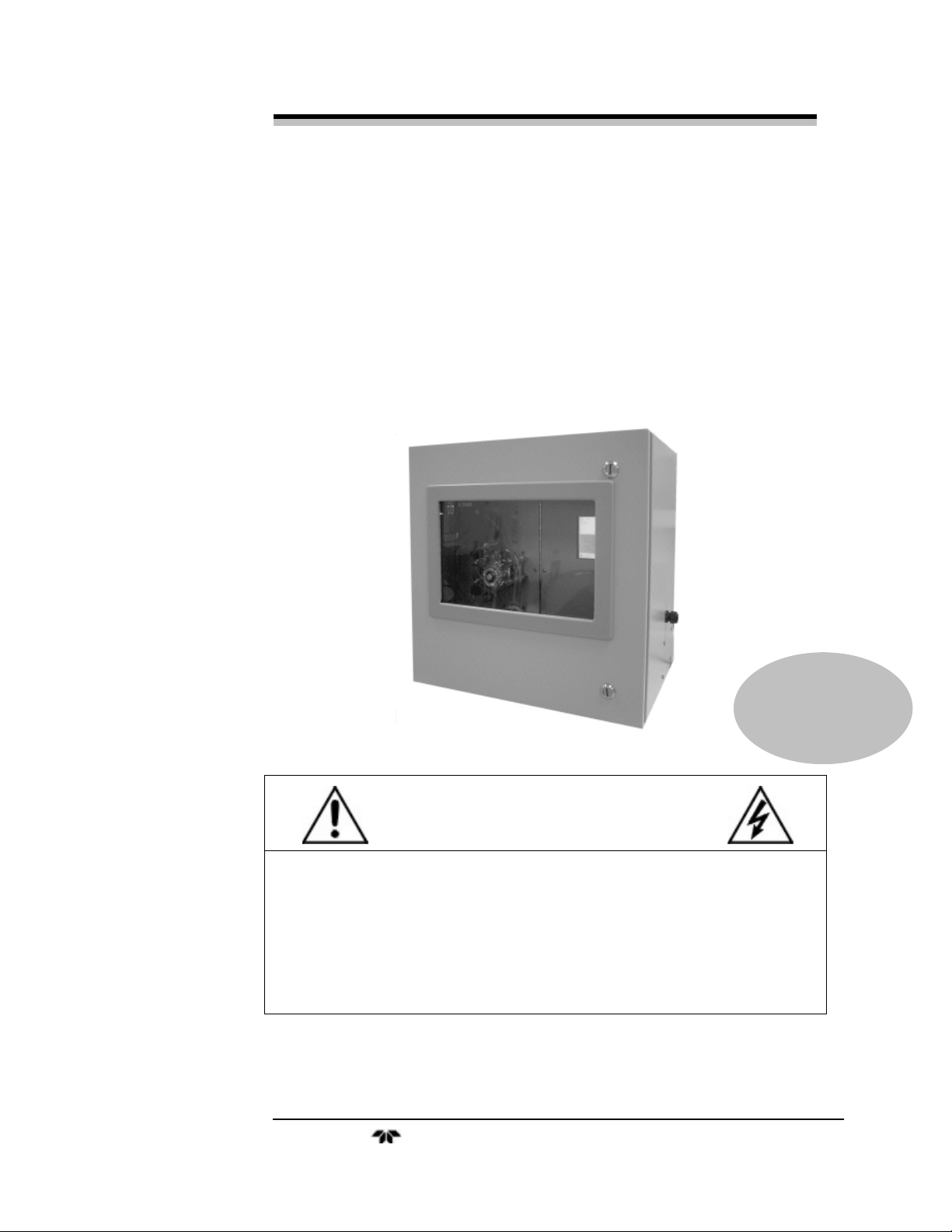
instrument. The Model 6750 TOC is shown in Figure 1-1.
1.1 Main Features of the Analyzer
The Model 6750 TOC Analyzer is sophisticated, yet simple to use.
The main features of the analyzer include:
• TC (Total Carbon) analysis
• NPOC (Non-purgeable organic carbon) analysis
• TOC-True Analysis (including volatile organics)
• Microsoft Windows Touch Screen Computer with Paperless
Chart Recorder
• Two alarm levels
• One Master Fault Alarm
• 3 analog 4-20 mA outputs
Page 14

Introduction Model 6750
Teledyne Analytical Instruments 2
• RS-232C and RS-485 outputs
• Separate electronics and liquid compartments
1.2 Options
The following options are available for the Model 6750 TOC
Analyzer and are described in Appendix A.3:
• Correlated BOD/COD
• Dual NDIR Analyzers
• Benchmark/Auto Validation
• Auto-Cal/Auto-Clean
• Automatic Multi-Range
• Multi-Stream Analysis
• DBPR Drinking Water
1.3 Typical Applications
With excellent TOC accuracy from low parts-per-million to high
concentration levels of salt-free samples, the Model 6750 is used in a
variety of applications including:
Boiler Feedwater
Standard Method 5310 C/D Cooling Water
EPA 415.1 Drinking Water
EPA 9060 Wastewater (limited)
ASTM D 4839-88 River Water
ASTM D 4779-88 Oil in Water
1.4 Intended Use of the Analyzer
The Analyzer is exclusively designed for monitoring of Total
Organic Carbon (TOC) in water. This intended use involves carefully
following the instructions provided in this manual and observing all
indicated warnings, hints and instructions.
Page 15
Total Organic Carbon Analyzer Introduction
Teledyne Analytical Instruments 3
All other types of usage beyond the intended use stated above, are
considered as misuse of the analyzer. The supplier assumes no
responsibility for damage incurred as the result of misuse of the product.
1.5 Operator Interface
The Model 6750 Analyzer is housed in a rugged metal case and
may be wall or rack mounted for operator convenience.
The enclosure is equipped with a viewing window on the front
panel and all operator serviceable components may be viewed through
the cabinet window, including the display.
Figure 1-1: The Model 6750 TOC Analyzer (Front door removed)
All operations are automatic and are performed using the Windows
Touch Screen Computer.
Page 16

Introduction Model 6750
Teledyne Analytical Instruments 4
Page 17

Total Organic Carbon Analyzer Theory of Operation
Teledyne Analytical Instruments 5
Theory of Operation
2.1 Overview
The Model 6750 Analyzer uses the UV/Heated Persulfate method
of analysis and is well-suited for many applications involving accurate
TOC analysis. The basic analyzer is configured for maximum utility
using an advanced Microsoft™ Windows-based CE computer with touch
screen. The analyzer is suitable for both general purpose and/or
hazardous area classifications, if properly configured with required
safety equipment.
2.2 Background
TOC analysis is the primary screening tool and control parameter
for all water based applications but there are some discrepancies or
misunderstanding in just what TOC is comprised of.
Many manufacturers claim TOC analysis capability without
disclosing the limitations of their methods. Some treat all “TOC
analyzers” as a commodity, with no distinguishing characteristics among
them. Analytical results reported by the user can therefore be
questionable, unless the TOC method is matched to the analytical
requirement.
The following discussion is intended to provide the user adequate
information in order to allow intelligent cost/performance trade-offs and
select the appropriate TOC method for each application. The Model 6750
TOC Analyzer performs the following analyses on the SAME sample:
• TC: Total Carbon
• NPOC: Non-Purgeable Organic Carbon
• TIC: Total Inorganic Carbon
• POC (VOC): Purgeable Organic Carbon or Volatile Organic
Carbon
• TOC-True : Total Organic Carbon
Page 18
Theory of Operation Model 6750
Teledyne Analytical Instruments 6
To perform correct TOC analysis, the analysis system must be
capable of measuring all constituents of organic carbon present in the
sample: Non-Purgeable Organic Carbon (NPOC) and Purgeable
Organic Carbon (POC). Correct TOC analysis must also exclude the
Total Inorganic Carbon (TIC) interference.
Figure 2-1 is a basic, commonly used technique to measure the
NPOC, sometimes referred to as “TOC-Direct”.
Figure 2-1: NPOC or TOC – Direct Method
In this method, acid is added to the sample, lowering its pH to
approximately 2.0, at which point the carbonates present in the sample are
converted to dissolved CO2. In the sparger, the carrier gas strips (sparges)
the CO2 converted from the TIC and vents it, along with any purgeable
(volatile) organics, leaving only NPOC in the sample. The resultant NPOC
is then oxidized to CO2 in the reactor and measured by the CO2 detector as
NPOC in the sample, often referred to and reported erroneously as “TOC”.
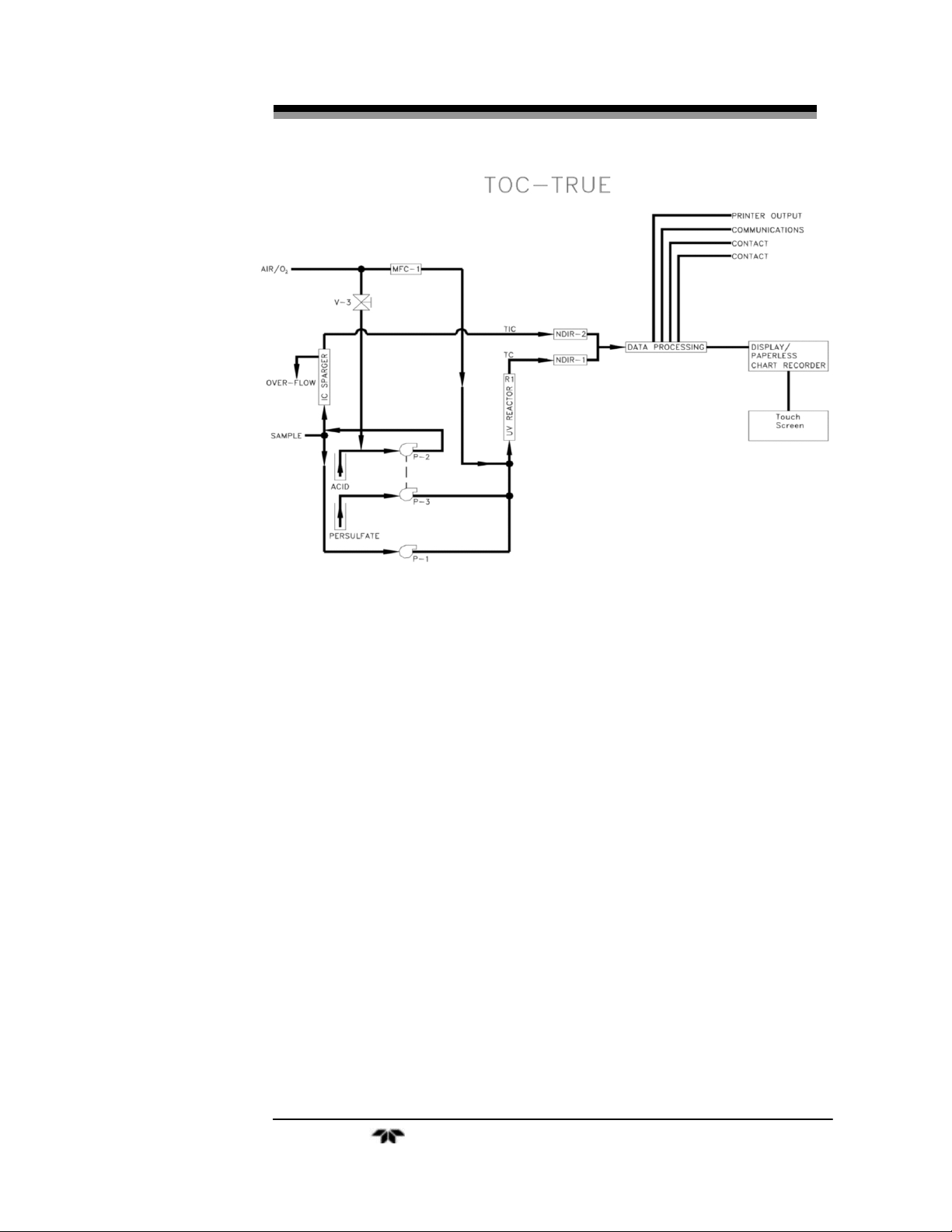
In Figure 2-2 a preferred method of performing a “TOC- True”
analysis is shown.
Figure 2-2: TOC – True Method
In this case, acid is added to the sample, lowering its pH to
approximately 2.0, at which point the carbonates present in the sample
are converted to dissolved CO2. In the sparger, the carrier gas strips
Page 19

Total Organic Carbon Analyzer Theory of Operation
Teledyne Analytical Instruments 7
(sparges) the CO2 converted from the TIC and it is measured by an
independent CO2 detector as “TIC”. POC is also stripped from the
sample in the sparger as HC, but the HC is undetected by the CO2
detector and does not interfere with the TIC measurement.
A portion of the same sample is also directed to the oxidation
reactor, where inorganic and all organic carbon is converted to CO2 and
detected by a second CO2 detector as “Total Carbon”.
A mathematical subtraction of the TIC from the TC measurement
yields a complete, Total Organic Carbon analysis performed as a “TOCTrue” method.
TOC - True = TC - TIC
The difference between the Model 6750’s TOC-True Method
and other simple (TC-TIC) subtraction methods is that most other
simple TC-TIC subtraction methods only deal with a TC measurement,
then a separate TIC measurement and a simple mathematical difference
to derive a “TOC” analysis.
In the TOC-True method used by the Model 6750, the analyzer
actually performs both TC and TIC measurements simultaneously and
continuously on the same sample. The TOC Measurement Basics and
Methods are illustrated in Figures 2-3 and 2-4.
In conclusion:
1. NPOC is the preferred method if no POC/VOC is present
in the sample.
2. TOC-True is the preferred method if POC/VOC exists in
the sample and a TOC analysis is desired which includes
all organic carbon species, for a TOTAL Organic Carbon
measurement.
Page 20
Theory of Operation Model 6750
Teledyne Analytical Instruments 8
Figure: 2-3: TOC Measurement Basics
Figure 2-4: UV/Persulfate Method
Page 21

Total Organic Carbon Analyzer Theory of Operation
Teledyne Analytical Instruments 9
2.3 The UV/Heated Persulfate Method of Analysis
In the UV/Heated Persulfate Method as used by the Model 6750,
the sample is initially mixed with acid and directed to the sparger. For
TOC-Direct (NPOC) analysis, the CO2 converted from the inorganic
carbon is sparged out of solution by the carrier gas and vented to
atmosphere. Any volatile organic loss would occur at this point, exiting
the sparger as HC gas. For TOC-True, the TIC-related CO2 is measured
by the NDIR CO2 detector, which is blind to the HC. For NPOC
analysis, the liquid, carbonate-free sample is then directed to the UV
reactor, where the remaining organic carbon is oxidized to CO2 and
measured by the NDIR as a "TOC-Direct" (or NPOC) analysis.
NDIR analysis of CO2 is specific and interference-free and is used
in all critical and regulatory applications. The TOC-Direct method is the
most accurate TOC analytical method, as determined by the EPA and
other governmental agencies. Teledyne also offers conductivity
detection but it is of limited use in these applications and is not proposed
as a primary detection method for TOC analysis, especially in critical
industrial applications where multiple or unknown analytes are present.
Figure 2-5 compares both CO2 detection methods.
For the TC analysis, the combined liquid/gas sample is sent directly
to the reactor, where all carbon (including the volatile HC) is converted
to CO2. The NDIR thus measures the TOTAL CO2 (including that
generated from the TIC, volatile HC and NPOC) and reports it as "TC."
The important thing is that all measurements are made on the same
sample, eliminating potential sample introduction errors and multiple
sampling inaccuracies.
Page 22
Theory of Operation Model 6750
Teledyne Analytical Instruments 10
Figure 2-5: Comparison of TOC Measurement Technologies
Page 23

Total Organic Carbon Analyzer Theory of Operation
Teledyne Analytical Instruments 11
2.4 Subsystems Principles of Operation
The Model 6750 TOC Analyzer is comprised of five subsystems:
1. Sample Handling
2. Inorganic Carbon Removal
– OR –
Inorganic Carbon Analysis/TOC-True Method
3. Oxidation
4. NDIR CO2 Gas Detection
5. Electronic Signal Processing, Display and Control
The sample system is designed to accept the liquid sample and any
required reagents, transporting them through the analyzer to the
appropriate components. For TOC (actually, NPOC) analysis, the
sample is pumped initially to the sparger, where it is mixed with acid to
lower the pH between 2.0 and 3.0. At that pH, all inorganic
carbon/carbonates are converted to dissolved CO2 gas, which is sparged
out of the liquid solution by the air/O2 carrier gas. At this point, any
volatile organic carbon is also sparged out and lost for inclusion in the
“TOC” analysis, unless a TOC-True analysis is performed, as described
below.
2.4.1 Sample Handling
The sample is processed through the analyzer in two phases: liquid
and gaseous
2.4.1.1 LIQUID PHASE SAMPLE HANDLING
Referencing Figures 2-6 and 2-7, the sample is introduced to the
analyzer with a self-priming peristaltic pump (P-4). It is then initially
directed to the Inorganic Carbon (IC) Sparger, where it is mixed with
acid delivered by pump (P-2). The pH of the solution is lowered to
approximately 2, converting the inorganic carbon to CO2, which is
sparged out by the carrier gas and measured as Total Inorganic Carbon
(TIC) by an infrared analyzer (NDIR-2) in the “TOC-True” mode.
The “TOC-True” mode is the preferred method of use if volatile
hydrocarbons are present, which would otherwise be lost in the sparging
process. Thus, through subsequent analysis of Total Carbon (TC) and
Page 24
Theory of Operation Model 6750
Teledyne Analytical Instruments 12
actual measurement of the TIC, a more accurate TOC is achieved since
(TOC = TC - TIC).
“TOC-Direct” mode is preferred for accuracy when no or little
volatiles are present. In this mode, the carbonate-free sample is
extracted from the organic carbon reactor and measured directly as
TOC. Pump (P –1) continuously introduces the carbonate-free sample
to the reactor. No valves or complicated injection mechanisms are
required. The remaining organic carbon is oxidized to CO2 in the
reactor. The resultant gaseous stream is directed to a gas/liquid
separator and then to the NDIR. The CO2 gas is analyzed by the
infrared analyzer (NDIR) as a direct correlation of Total Organic Carbon
(TOC).
A computer controls all functions and outputs. A “Touch Screen”
provides operator interface and a paperless chart recorder utility.
Figure 2-6: Sample Handling for TOC -Direct
Page 25
Total Organic Carbon Analyzer Theory of Operation
Teledyne Analytical Instruments 13
Figure 2-7: Sample Handling TOC-True
2.4.2.2 GAS PHASE SAMPLE HANDLING
Referencing Figure 3-5 and “As Built” drawings in the Appendix, a
carrier gas of (99.8%) pure oxygen or CO2 and hydrocarbon-free air is
required. Erroneous TOC analysis will occur if the carrier gas has these
impurities, since both CO2 and Hydrocarbon gases will contribute a
higher TOC value to the analysis than is actually present in the sample.
An Oxygen Generator (P/N ST200025) is available from Teledyne
that separates oxygen from the ambient air. It is a pressure swing
absorption PSA device requiring only electricity only to operate. Also
available from Teledyne is an Instrument Air Purifier (P/N ST200019).
This device can supply the oxygen demands of the instrument using
facility instrument air.
Facility carrier gas is introduced to the analyzer, regulated at 15± 2
psi, and then controlled by an internal mass flow controller (MFC-1) to
precisely control the flow rate of the carrier.
Note: Precise carrier gas flow control is mandatory for accurate
Page 26

Theory of Operation Model 6750
Teledyne Analytical Instruments 14
TOC analysis in a continuous, on-line TOC analyzer.
The CO2 generated by the oxidation of carbon in the reactor is read
by the NDIR as a percentage concentration of the CO2 in the carrier gas.
CO2 (TOC)
CO2 (TOC) + Carrier
Any increase or decrease of the carrier flow rate will have a
corresponding inverse effect on TOC reported value, (eg. double the
carrier flow rate, reported TOC will approximate ½ of actual sample
TOC concentration).
The Model 6750 uses a computer-controlled mass flow controller
rather than a less accurate system consisting of pressure regulation with
a flow meter in a capillary system.
The inorganic carbon removal system (sparger) flow rate is
controlled by needle valves (V1 & V2) set at the factory. The operator
will note bubbles through the liquids in the sparger, which is stripping
the CO2 converted from the carbonates to eliminate the potential
interference from inorganic carbon in TOC analysis.
The carrier gas directs the CO2 and other products of oxidation
from the reactor to the Gas/Liquid Separator (GLS), where liquid waste
is directed to drain and gases containing CO2 and other gaseous products
of oxidation are directed to the CO2 specific NDIR. The CO2
concentration is directly related to sample TOC concentration and is
reported accordingly.
2.4.2 Inorganic Carbon Removal/Analysis
The choice of either TOC –Direct (NPOC) or TOC-True analysis
involves a method of either measuring the TIC (for a TOC-True
analysis) or not (for a Non-Purgeable TOC analysis only). The Model
6750 Analyzer can perform either method. The TOC-True method
measures the inorganic carbon and is able to detect volatile organic loss
in the sparger. The NPOC analysis ignores the volatile organics for a
less precise NPOC analysis if organic volatiles are present.
The sparger used in the Model 6750 is a gas/liquid counter-flow
stripper. Actual acid addition depends on the amount of sample
buffering and pH. Factory set-up is for a nominal sample pH of 7.0, to
Page 27
Total Organic Carbon Analyzer Theory of Operation
Teledyne Analytical Instruments 15
be reduced to approximately 2.0 to 3.0. If the sample pH is not properly
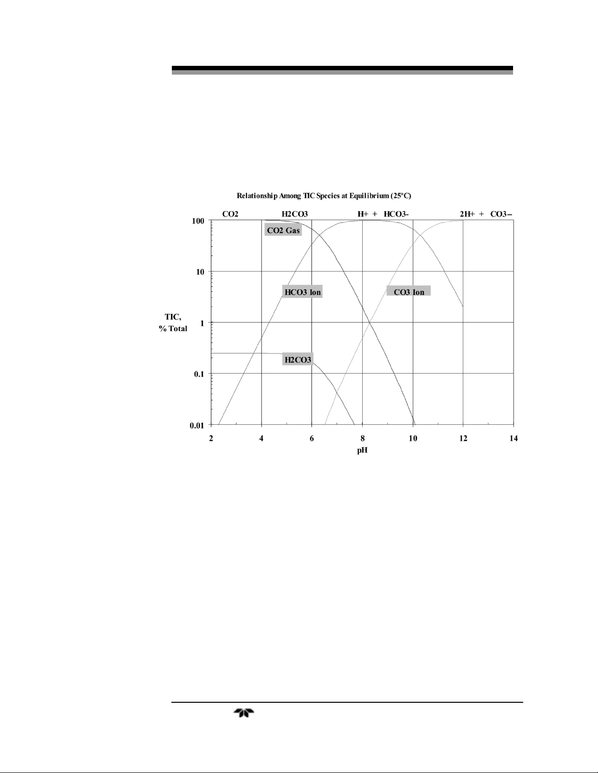
reduced as described in Figure 2-8, increase the normalcy of the acid
reagent until the water exiting the sparger drain is between 2.0 and 3.0.
Figure 2-8: Relationship Between TIC and pH
2.4.3 Oxidation
The UV reactor and persulfate reagent provide oxidation of the
carbon to CO2. The UV reactor consists of the following:
• Mounting enclosure with viewing window
• Borosilicate reactor body
• Heater/Temperature sensor
• UV Lamp
• Miscellaneous fittings and clamps
Page 28
Theory of Operation Model 6750
Teledyne Analytical Instruments 16
The construction of the patented UV reactor in the Model 6750
affords superior oxidation by precisely controlling the sample
temperature, adding a precise amount of ultra-pure persulfate reagent
(P/N ST40000) and precisely controlling the carrier gas flow rate.
Pump (P-1) continuously meters a precise amount of carbonate-free
sample from the sparger to the UV reactor. Pump (P-3) continuously
meters a precise amount of persulfate reagent to the reactor. Mass Flow
Controller (MFC-1) precisely controls the carrier flow rate. Refer to
Figures 2-6 and 2-7.
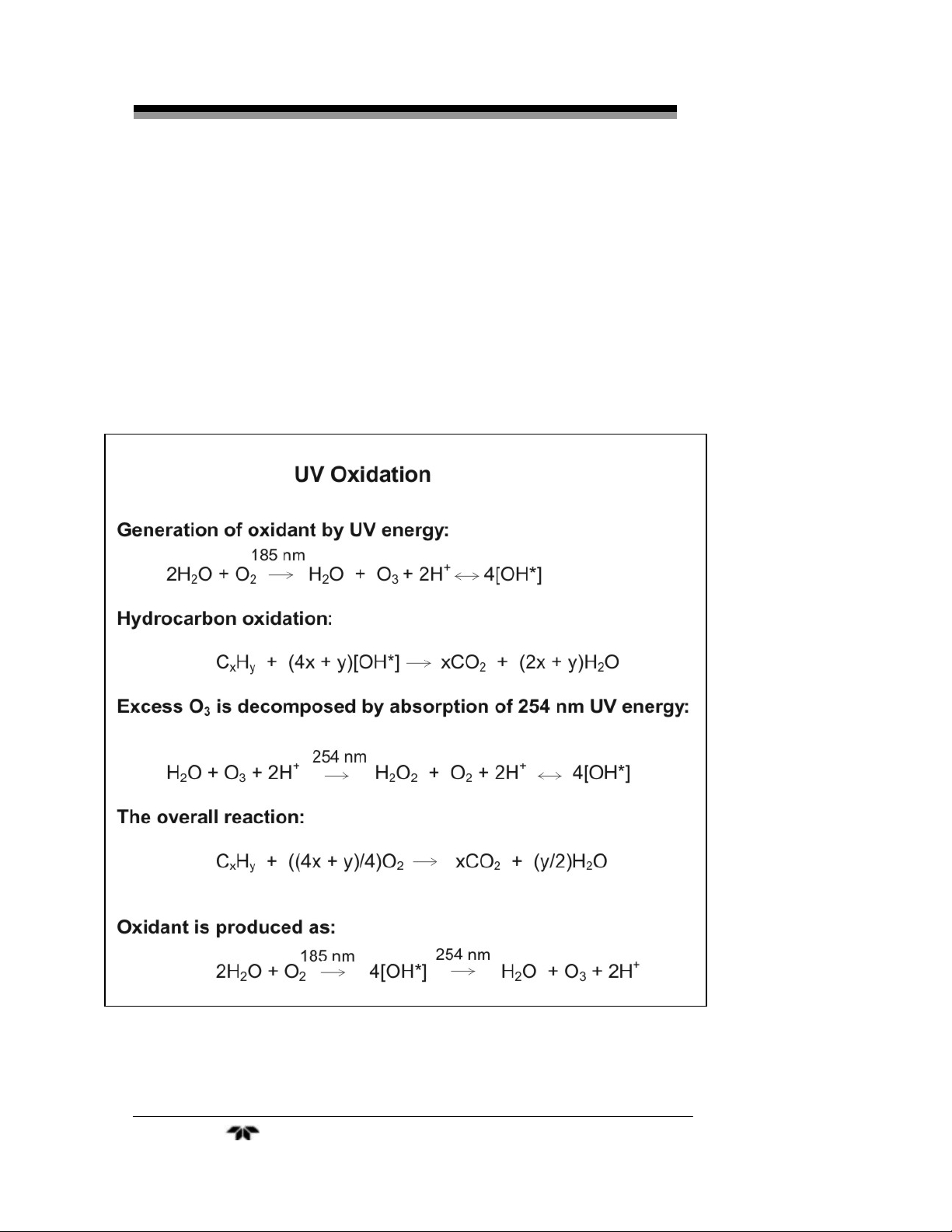
Figure 5-10 shows UV oxidation methodology.
Figure 2-9: Oxidation Reactions
Page 29
Total Organic Carbon Analyzer Theory of Operation
Teledyne Analytical Instruments 17
2.4.4 NDIR CO2 Gas Detection
The key component for reliable TOC analysis is the precise and
interference-free detection of CO2. The Model 6750 NDIR unit requires
very little maintenance because of its ability to handle the corrosive
gases generated in TOC analysis. This is due in part to its non-reflective
borosilicate sample cell. It has no moving parts which further reduces
the maintenance load and it uses an internal self-calibrating technique.
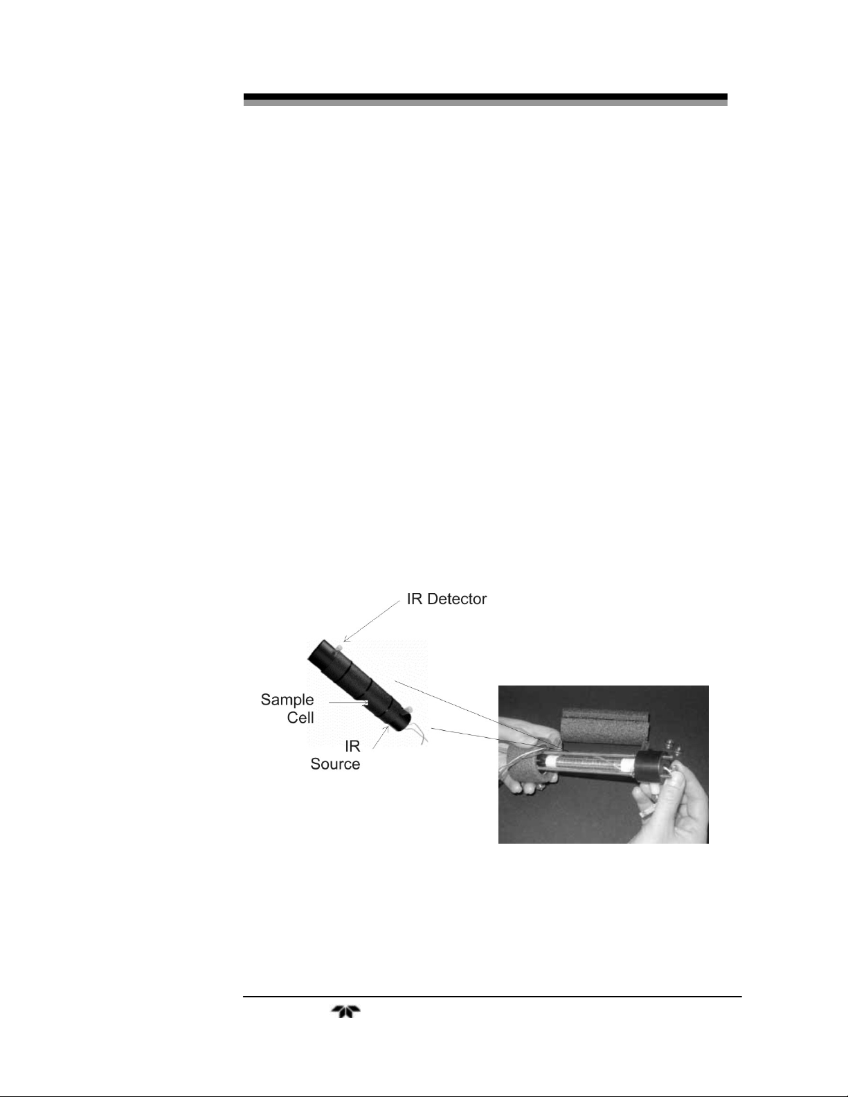
The NDIR unit is shown in Figure 2-10. Some of the features of the
NDIR unit are as follows:
• Specific, interference-free CO2 detection
• Dual-wavelength rationing compensates for drift
• Computer-controlled for accuracy
• Sapphire protected optics
• Non-corrosive, non-reflective sample cell (borosilicate)
• No moving parts or tools required for easy maintenance and
service
• No critical realignment required
Figure 2-10: Model 6750 NDIR Unit
The NDIR CO2 detector uses a completely solid state, dual
wavelength ratioing technique with a single borosilicate sample cell that
Page 30

Theory of Operation Model 6750
Teledyne Analytical Instruments 18
requires no wall reflectivity and is completely resistant to corrosive
gases. The NDIR unit requires no optical chopper motor or mechanical
devices but utilizes a single flashing infrared source to optically “chop”
the infrared (IR) beam, which equally irradiates CO2/reference detectors.
Using a reference eliminates water vapor interference. The nonreflective, corrosive resistant sample cell removes the requirement for
chemically removing acid gases prior to detection.
Automatic gain control (AGC) is employed during the
reference/sample cycle to compensate for such factors as IR source
deterioration, dirty optical windows, etc. When the AGC level reaches a
predetermined threshold, an optics alarm is activated. Malfunctions of
major NDIR components are detected and indicated as an alarm,
providing “fail-safe” operation. Signal detection is completely
synchronous and because of the differential ratioing technique, drift is
virtually eliminated.
All critical optics are protected by sapphire windows. The NDIR
optical bench can be easily disassembled and windows cleaned (rarely
ever required) and reassembled within fifteen (15) minutes, without
realignment or the use of any tools.
The benefit of this absolute measuring, dual line spectral
differential analytical technique, is that it provides simple, direct
measurement of all CO2 contributing factors (including background) for
a true and accurate calibration, and precisely offsets these effects for
very accurate TOC determinations.
2.4.5 Electronic Signal Processing, Display and Control
A true, industrialized Microsoft Windows™-CE Computer offers
complete automatic control of the analyzer, including the following:
• Benchmark/Auto-Validation
• Auto-Calibration
• Auto-Cleaning
• On-Board Historical Data for up to one (1) year
• Paperless Chart Recorder
• Diagnostics
• Networking (RS-232C/485)
Page 31

Total Organic Carbon Analyzer Theory of Operation
Teledyne Analytical Instruments 19
2.4.5.1 BENCHMARK/AUTO-VALIDATION
Benchmark is the European NAMUR* specified validation
technique, whereby on command a chemical calibration standard is
automatically introduced to the analyzer and the response is compared to
the previous analyzer calibration. If the response falls within a certain
specified limit, the computer/output indicates “Benchmark Passed”. If
the response falls outside specified performance limits, either a
“Maintenance Request” or a “Fault” alarm is activated, depending on
preset tolerances.
Thus, in cases of process spills, when the analyzer performance is
questioned, Benchmark can rapidly and automatically validate analyzer
performance. It eliminates time consuming and unnecessary
recalibration cycles, which take the analyzer out of service just when it
is most critically needed. Benchmark may be on-demand, or operator
programmed for designated day and time activation on a repetitive basis.
On command (manual or automatic by selection of day/time), the
combination of valves V3 and V4 divert the sample and introduce a
liquid calibration solution to the analyzer. This is the same calibration
solution used to previously calibrate the analyzer, “end-to-end”. If the
TOC value from the calibration solution falls within a limit (generally
set at 5% of the previous calibration), then “Benchmark Passed” will be
displayed and remotely reported. If the TOC “Benchmark” solution
falls outside the set tolerance, then a “Benchmark Failed” message and a
“Maintenance Request” are reported.
2.4.5.2 AUTO-CALIBRATION
On command (manual or automatic by selection of day/time), the
combination of valves V3 and V4 alternately introduce D. I. water for a
“Zero” calibration and the “Span” solution. The computer then resets
the analyzer to the new calibration values.
2.4.5.3 AUTO-CLEANING
On command (manual or automatic by selection of day/time), the
combination of valves V3 and V4 operate to introduce a “cleaning”
solution, depending on the chemical constituents of the sample. Acid or
persulfate is generally used.
Page 32

Theory of Operation Model 6750
Teledyne Analytical Instruments 20
Page 33

Total Organic Carbon Analyzer Installation
Teledyne Analytical Instruments 21
Installation
This manual contains “AS BUILT” drawings and a parts list to aid
in the installation and operation of the analyzer. These drawings should
be referred to when ordering spare parts, operating or servicing the
equipment. See the Appendix for the AS BUILT drawing package.
Installation of the Model 6750 On-line UV/Heated Persulfate TOC
Analyzer includes:
1. Unpacking
2. Mounting
3. Electrical Connections
4. Gas Connections
5. Testing the System
3.1 Unpacking the Analyzer
The analyzer is shipped with all the materials you need to install
and prepare the system for operation. Carefully unpack the analyzer and
inspect it for damage. Immediately report any damage to the shipping
agent.
3.2 Mounting the Analyzer
The analyzer is for indoor use in a general purpose area. The
Hazardous Area Option should be used for applications involving
hazardous areas.
The standard model is designed for wall or rack mounting. Figure
3-1 is an illustration of the mounting and Figure 3-2 shows the required
front door clearance. There are four mounting holes – one in each corner
of the enclosure. Refer to “As Built” drawings in the Appendix.
Page 34

Installation Model 6750
Teledyne Analytical Instruments 22
Figure 3-1: Analyzer Dimensions
Figure 3-2: Required Door Clearance
Page 35

Total Organic Carbon Analyzer Installation
Teledyne Analytical Instruments 23
All operator controls and serviceable components are mounted on
the control panel, which is hinged and doubles as the door that provides
access to those components not normally requiring maintenance.
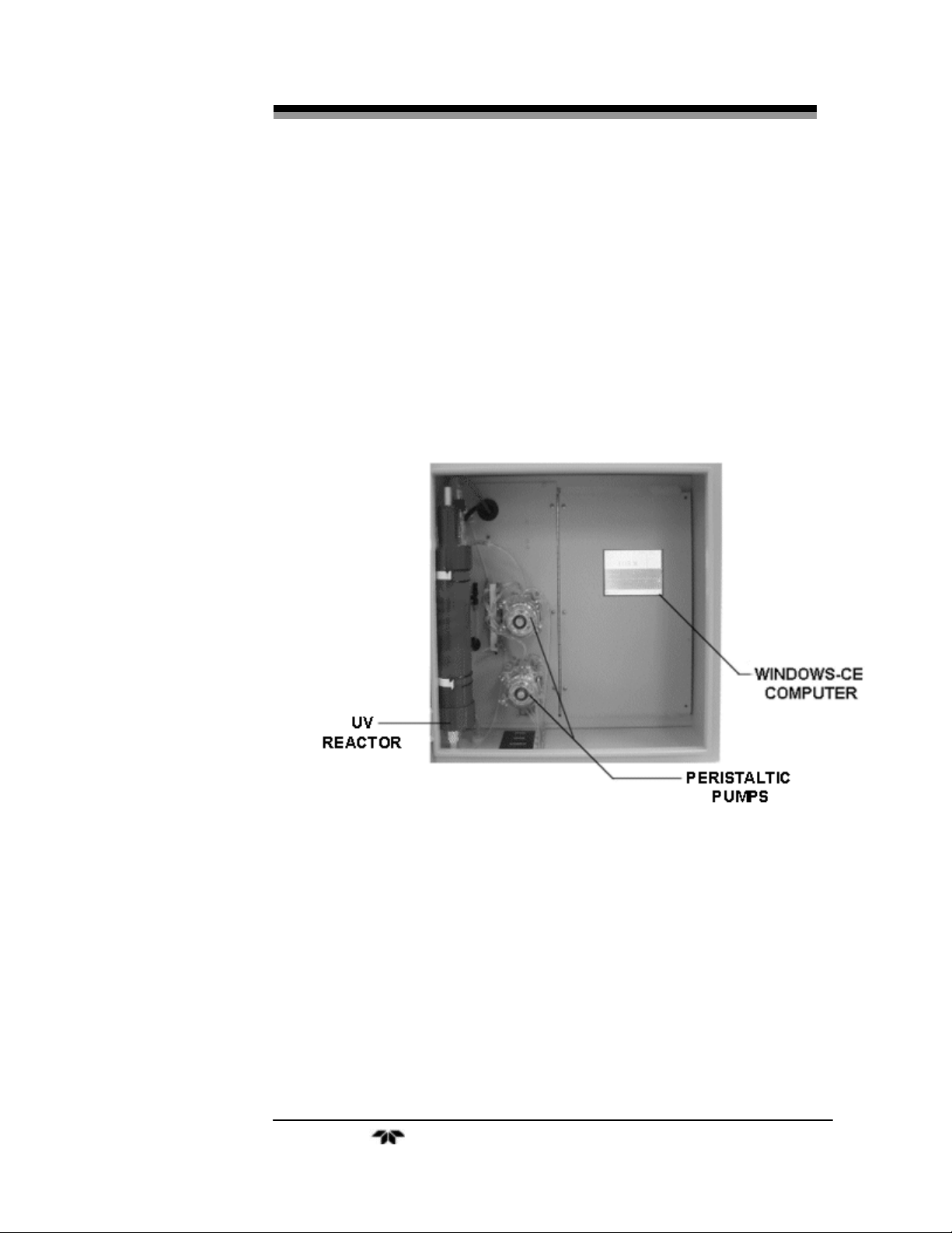
Internal components of the Model 6750 TOC Analyzer are shown
in Figure 3-3.
Figure 3-3: Internal Components of the Model 6750 Analyzer
3.3 Electrical Connections
Figure 3-4 shows the analyzer electrical/electronics connections for
power, communication, and both digital and analog concentration
outputs. See also the AS-BUILT drawing package included in the
Appendix.
3.3.1 Power Connection
The universal power supply requires an 85-250 VAC, 47-63 Hz
power source.
For safe connections, ensure that no uninsulated wire extends
outside the connectors they are attached to. Stripped wire ends must
insert completely into terminal blocks. No uninsulated wiring should be
able to come in contact with fingers, tools or clothing during normal
operation. Electrical/Electronics hookups include the following:
Page 36

Installation Model 6750
Teledyne Analytical Instruments 24
• Power Connection Universal AC Power Source
• Primary Input Power
CAUTION: POWER IS APPLIED TO THE INSTRUMENT’S
CIRCUITRY AS LONG AS THE INSTRUMENT IS
CONNECTED TO THE FACILITY POWER SOURCE.
THE FACILITY MUST HAVE AN EXTERNAL POWER
SWITCH TO REMOVE PRIMARY POWER FROM THE
ANALYZER.
• Analog Output Connections
• Alarm Connections
Figure 3-4 shows where the electrical connections are made to the
instrument.
3.3.2 Analog Outputs
There are two analog output signal connections. There are two
wires per output with the polarity noted. See “As Built Drawings” in the
Appendix. The outputs are non isolated 4-20 mA.
Figure 3-4: Electrical Connections to the Model 6750
Page 37

Total Organic Carbon Analyzer Installation
Teledyne Analytical Instruments 25
3.3.3 Alarm Connections
The Model 6750 is equipped with two concentration alarms and
one analyzer malfunction alarm. The three alarm-circuit connectors use
spring terminals for making connections to internal alarm relay
connects. Each alarm provides a set of Form C contact with both
normally open and normally closed contact connections. The contact
connections are indicated by diagrams on the rear panel. They are
capable of switching up to 3 amperes at 250 VAC into a resistive load.
See “As Built Drawings” in the Appendix. The connections are:
• Threshold Alarms:
• Can be configured as high (actuates when concentration
is above setpoint), or low (actuates when concentration is
below threshold).
• Can be configured as failsafe or non-failsafe.
• Can be configured as latching or non-latching
• Malfunction Alarm
3.3.4 RS-232 Serial Connection
An RS-232 port is provided for serial communication (MODBUS).
Connect a standard RS-232 cable from the computer to the RS-232 port
on the main board.
3.4 Gas/liquid Connections
Refer to the “As Built Drawings” in the Appendix for details and
Figure 3-5.
The Model 6750 Analyzer provides easy access for liquid, gas, vent
and drain connections.
3.4.1 Liquid Connections
Liquid phase sample connections include the following: (See
Figure 3-5):
• Sample (On-Line)
• D. I./Dilution Water
• Calibration Standard
Page 38

Installation Model 6750
Teledyne Analytical Instruments 26
• Reagents
• Drain (s)
Connect these lines as per Figure 3-4 and the AS-BUILT drawings
in the Appendix. Make sure there are no restrictions or kinks in the
sample lines.
Figure 3-5: Gas and Liquid Connections to the Analyzer
3.4.2 Gas Connections
The gas connections include:
• Sample Gas
• Carrier Gas
• Vent
• Calibration Gases (zero and span)
Page 39

Total Organic Carbon Analyzer Installation
Teledyne Analytical Instruments 27
With the exception of the vent and carrier gas inlet, all other gas
connections are made on the same bottom panel as the liquid connections
and are shown in Figure 3-5. The NDIR vent and carrier gas connections
are made on the left side of the unit.
Gas Carrier Connections:
The facility carrier gas must be free of CO2 and hydrocarbons and
be regulated to 15±2 psi and connected as shown in “As Built”
Drawings in the Appendix).
NDIR Vent (gas exhaust):
Exhaust connections must be consistent with the hazard level of the
constituent gases. Check Local, State, and Federal laws, and ensure that
the exhaust stream vents to an appropriately controlled area if required.
CAUTION: OPERATING THE UNIT WITHOUT CARRIER GAS
CAN DAMAGE THE ANALYZER.
3.5 Checking the System
Before applying power to the instrument, check:
• All gas and liquid lines as well as vent and drains are
properly connected and there are no leaks in the lines or at
fittings.
• Power and signal wiring are correct and that there are no
frayed or loose wires that could cause a short.
Prior to powering up the system and using the instrument for
analysis, the system must be configured for your application and
calibrated. This is described in Section 4.
Page 40

Installation Model 6750
Teledyne Analytical Instruments 28
Page 41

Total Organic Carbon Analyzer Setup and Operation
Teledyne Analytical Instruments 29
Setup and Operation
Once the analyzer has been installed, it can be configured to your
application. To do this you will:
• Set system parameters
• Calibrate the instrument
• Define the analysis range. Then choose auto-ranging or
select a fixed range of analysis, as required.
• Set alarm setpoints, and modes of alarm operation (latching,
failsafe, etc.)
4.1 Analyzer Startup
Referring to the Installation section and “AS-BUILT” Drawings in
the Appendix, check the following:
1. Air/oxygen supply – This must provide a constant
pressure of 15 +/- 2.0 psi, ultra-pure oxygen or CO2–free
air at a flow rate up to 500 cc/minute. (Pre-purified air
may be used with optional Air Purifier P/N ST910003).
2. Drain Line – Check to see if the drain line is free of kinks
and loops and allows normal vented gravity flow to an
open receptacle (jar, pipe, etc.). AN AIR GAP AS
DEFINED IS MANDATORY.
CAUTION: FAILURE TO OBSERVE THIS WILL RESULT IN
IMPROPER OPERATION.
3. ELECTRICAL – Assure proper electrical installation.
Refer to facility requirements.
4. SAFETY – All customer and Teledyne specified safety
measures are followed.
Page 42

Setup and Operation Model 6750
Teledyne Analytical Instruments 30
Figure4-1: Drain Connections
5. On initial start–up or after UV Reactor or Glass Liquid
Separator (GLS) servicing, fill the U-Tube with D. I.
water as indicated in Figure 4-2.
6. After all of the above checks, turn analyzer ON by
activating the facility power switch. The system starts up
in Run Mode.
7. Immerse line from “sample” port of the analyzer into D.
I. water container.
8. Immerse persulfate line from the “persulfate” port of the
analyzer into persulfate container.
9. Immerse acid line from the “ACID IN” port of the
analyzer into ACID container.
Page 43

Total Organic Carbon Analyzer Setup and Operation
Teledyne Analytical Instruments 31
Figure 4-2: Gas Liquid Separator D. I. Filling
After reagents and DI have filled all tubing lines, it is
recommended to proceed with IR Calibration followed by cal (liquid
calibration) of the system. Then the analyzer may be placed in service.
4.2 Menus
The advanced design of the Model 6750 TOC Analyzer eliminates
complicated, routine, and sometimes confusing menus. The
operator/software interface is simple and easy to use. Menus prompt the
user for required actions or input.
The analyzer has no manual adjustments. All calibrations and
operations are computer controlled by the operator following menu
prompting and selection of the operation of choice.
The following menu and operation descriptions are intended to
guide the operator through all the functions of the analyzer.
After primary power (110/220VAC) has been applied to the
analyzer and self-diagnostic procedure has been completed, the system
automatically boots up to the following RUN Screen. If not, turn main
power OFF, then ON to reboot.
4.2.1 Run Mode
RUN – This is the normal analysis mode. In this mode, the display
indicates:
Page 44

Setup and Operation Model 6750
Teledyne Analytical Instruments 32
• The current TOC value,
• [IR] IR response
• [Flow] Carrier Gas Flow rate
• [m] Available Memory (kb).
4.2.2 Parameter Menu
Although your analyzer has been optimally configured for your
application, on initial startup the setup parameters should be verified
Consult Factory Settings for Your Application – “As Built Drawings” in
the Appendix.
To get to the Parameters menu:
1. From the Run Screen, select [EDIT]. The following
menu will appear.
Note: Options not included in your analyzer will have no
response, if selected.
Page 45

Total Organic Carbon Analyzer Setup and Operation
Teledyne Analytical Instruments 33
2. From this menu, select:[Parameters]
The following screen appears:
This is the Parameters menu from which the analyzer may be
configured to suit the requirements of the operator
Verify the following settings are correct or select the desired
settings: (Consult “As Built Drawings’ in the Appendix and Factory
Settings Chart – Page V”)
• Carrier Flow Rate
• Liquid Range
Note: The “Liquid Range” setting is that value to which the full-
scale output range is to be set (not the value of the Liquid
Span).
4.2.3 Alarm Settings
The next settings to verify or set are the Alarm Settings.
To adjust the alarm settings:
From the [Edit] Menu, select [Alarms].
The following Menu appears:
Page 46

Setup and Operation Model 6750
Teledyne Analytical Instruments 34
From this menu verify or change the concentration alarm setpoints
using the onscreen scroll arrows.
4.2.4 Stream Sequencer
If your analyzer has been configured for a multi-stream sequencer
(P/N ST200009), from the [Edit] Menu, select [Sequencer]. The
following menu appears:
From this menu, you can:
• Configure the duration of analysis for each stream (how long
it will analyze that stream before selecting the next stream)
• Configure the changeover time (to allow the prior stream to
pass through sampling systems and clear the analyzer before
analysis of the next steam begins),
• Enable and disable each stream analysis (for example, to
concentrate on only one stream).
The following window is illustrative of a dual stream [Run] screen.
Page 47

Total Organic Carbon Analyzer Setup and Operation
Teledyne Analytical Instruments 35
4.2.5 D/DBPR
This optional utility allows convenient external pH calibration and
input of alkalinity data consistent with the D/DBPR requirements
If your analyzer has been configured for the D/DBPR option, from
the following [Edit] Menu, select [D/DBPR].
The following screen appears:
Page 48

Setup and Operation Model 6750
Teledyne Analytical Instruments 36
The following window is illustrative of the D/DBPR [Run] screen.
4.3 Detailed Calibration Procedures
1. Although the instrument has been calibrated to your
specifications at the factory, it should be rechecked after
satisfactory installation and periodically calibrated as
suggested for your application.
2. Instrument calibration is performed by an “end-to-end”
method, whereby a known organic carbon chemical
standard solution is introduced to the analyzer and the
analyzer is “spanned” to that value.
3. Organic and Inorganic Carbon Standards:
a. (Potassium Hydrogen Phthalate) is recommended for
the organic carbon standard solution.
b. Sodium Carbonate is recommended for the inorganic
carbon standard.
c. Table 4-1 provides the concentration to be used for
two ranges of different chemical compounds (organic
& inorganic carbon).
d. Ratioing of these concentrations will provide other
ranges for the span solution.
Page 49

Total Organic Carbon Analyzer Setup and Operation
Teledyne Analytical Instruments 37
Table 4-1: Preparation of Standards (TOC/TIC)
ORGANIC COMPOUNDS
100 mg/Liter
TOC (AS CARBON)
1000 mg/Liter
TOC (AS CARBON)
Ethylene Glycol
.233 ml/L H20
2.33 ml/L H20
Methanol
.337 ml/L H20
3.37 ml/L H20
Ethanol
.242 ml/L H20
2.42 ml/L H20
Acetone
.204 ml/L H20
2.04 ml/L H20
Carbon Tetrachloride
.807 ml/L H20
8.07 ml/L H20
Sucrose
.238 gm/L H20
2.38 gm/L H20
Urea
.500 gm/L H20
5.00 gm/L H20
Acetic Acid
.250 gm/L H20
2.50 gm/L H20
KHP (Potassium acid
phthalate)
.212 gm/L H20
2.12 gm/L H20
Glycine
.313 gm/L H20
3.13 gm/L H20
Sodium Stearate
.141 gm/L H20
1.41 gm/L H20
Succinic Acid
.246 gm/L H20
2.46 gm/L H20
Sodium Oxalate
.555 gm/L H20
5.55 gm/L H20
INORGANIC COMPOUNDS
50 mg/Liter
TIC (AS CARBON)
Sodium Carbonate
.442 gm/L H20
Potassium Carbonate
.575 gm/L H20
Ammonium Carbonate
.475 gm/L H20
Add amounts shown (in milliliters or grams) to clean dry, one liter
volumetric flask and dilute to one (1) liter with distilled, deionized
water.
4. Reagent Preparation:
PREPARATION OF ONE MOLAR SODIUM
PERSULFATE SOLUTION (OXIDIZING REAGENT)
Page 50

Setup and Operation Model 6750
Teledyne Analytical Instruments 38
CAUTION: SODIUM PERSULFATE IS A STRONG OXIDIZING
AGENT. TAKE ALL NECESSARY PRECAUTIONS AS
WITH HANDLING ANY CORROSIVE MATERIAL.
ALL CHEMICALS, INCLUDING WATER, SHOULD BE
REAGENT GRADE OR BETTER AND FREE OF
CARBON-CONTAINING COMPOUNDS.
THE CONTAINER USED SHOULD BE FLUSHED WITH
DISTILLED OR DEIONIZED (DI) WATER.
a. Dissolve 238 grams of ultra-pure reagent grade
sodium persulfate (P/N ST40000) into one (1) liter of
distilled water.
b. Do not heat reagent to dissolve, as this is not
necessary and can reduce the effectiveness of the
solution. It should be noted that some reagent grade
sodium persulfate is not really “pure”. All persulfate
supplied by Teledyne is guaranteed to have sufficient
purity for proper operation.
5. Acid Preparation:
Phosphoric Acid is the acid of choice.
PREPARATION OF PHOSPHORIC ACID SOLUTION
a. The container used should be flushed with distilled or
deionized (DI) water.
b. Add 117ml of 85% phosphoric acid to one (1) liter of
DI Water.
CAUTION: CONTACT WITH PHOSPHORIC ACID LIQUID OR
VAPOR CAN DAMAGE TISSUE, CAUSE EYE
DAMAGE, RESULT IN SEVERE BURNS AND CAUSE
LUNG AND RESPIRATORY DAMAGE. WEAR
PROPER PROTECTIVE CLOTHING AND SAFETY
GLASSES WITH SPLASH SHIELDS. TREAT ALL
ACIDS WITH CAUTION AND HANDLE WITH CARE.
ALWAYS WORK IN AN APPROVED FUME HOOD
WHEN HANDLING OPEN CONTAINERS OF ACIDS.
6. “End-to End” Calibration:
Page 51

Total Organic Carbon Analyzer Setup and Operation
Teledyne Analytical Instruments 39
Note: On the initial Startup, IR gas calibration should be
performed prior to liquid calibration
a. Select [CALIBRATE] from the main menu. The
following screen will appear:
b. Select [TOC].
The following screen appears:
c. Flow “ZERO” (D. I. Water) and allow NDIR reading
to stabilize. For maximum accuracy, especially at
lower ranges, this process may take 20 minutes.
When reading is stable, select [ZERO].
d. Flow Liquid Span Standard Solution. Allow NDIR
reading to stabilize, (approximately 15 minutes).
e. Select [SPAN]. It is recommended that the operator
continue to observe the reading and if not stabilized at
the desired span setting ± 2%, repeat the span
selection until stable.
Page 52

Setup and Operation Model 6750
Teledyne Analytical Instruments 40
f. If the calibration is acceptable, select [OK] or
[CANCEL] if not acceptable.
The analyzer is now calibrated and ready for analysis.
4.4 Operation
After proper installation and calibration, the instrument is ready to
be placed “ON-LINE” for continuous operation.
Note: For any non–standard or specific operational procedures,
please refer to the “INSTALLATION” and “AS–BUILT”
drawings in the Appendix or any Addenda that
accompanies this manual. If applicable, the Appendix or
Addenda will include details on your specific application,
which may involve valving, stream sequencing, automatic
calibration, etc.
The RUN screen will automatically appear on the screen. It will
also appear whenever the computer is rebooted or the power is turned
off and back on again. Figure 4-3 shows the RUN screen and identifies
the data fields.
Figure 4-3: The RUN Screen
Page 53

Total Organic Carbon Analyzer Setup and Operation
Teledyne Analytical Instruments 41
4.5 Shutdown
Prior to shutdown of the analyzer or performing service on the
reactor, flush D. I. water through all sample and reagent lines for at least
30 minutes to clean all tubing.
CAUTION: FAILURE TO OBSERVE ADEQUATE FLUSHING
COULD RESULT IN HARMFUL ACID BURNS AND/OR
A REACTOR CLOG.
4.6 Historical Data
Previous data may be obtained by selecting [CHART] from the
screen. The following menu will appear.
The display scale can be adjusted using the Select [TOC SCALE]
item from the [CHART] menu. The following screen will appear.
Edit Scale as desired.
Page 54

Setup and Operation Model 6750
Teledyne Analytical Instruments 42
To view the data produced in the last 24 hours, select [LAST 24
HOURS]. The following screen will appear:
Using the Scroll Bar, select the data to be viewed.
Selecting [HISTORICAL DATA] allows you to view any archived
data within the memory limits of the computer. A screen appears
which will allow you to select the archived time period desired. How
far back you can go depends on the available memory.
Page 55

Total Organic Carbon Analyzer Maintenance
Teledyne Analytical Instruments 43
Maintenance
5.1 Compupter-aided Testing
Prior to performing detailed troubleshooting procedures listed
below, first perform computer-aided testing of the analyzer, as follows:
1. From the screen, select [TEST]. The following menu
appears:
2. Select [SYSTEM DIAGNOSTICS]. The following
menu appears:
Page 56

Maintenance Model 6750
Teledyne Analytical Instruments 44
From this screen the operator may perform individual
testing of components related to functionality and
settings.
5.2 Troubleshooting
If you are experiencing trouble with your instrument, refer to Table
5-1: Troubleshooting.
Table 5-1: Troubleshooting
PROBLEMS
SOLUTION
Analyzer will not turn on
• Check fuse & power connections.
• Look for loose or damaged wiring.
• Check for 12V DC from power supply.
• Check power supply fuse.
Analyzer does not Calibrate, is
sluggish
• Look for & correct any liquid or gas line
leaks.
Analyzer is excessively noisy
• Check for leaks at tubing connections
Display not functioning
• Check cable connections
• Check power supply voltage
• Suspect:
• Malfunctioning Computer (P/N ST13039).
• Master Control Panel Assembly (P/N
ST13042-1)
Pump head not rotating
• Refer to section “Pumps” 12.3.12
• Verify that carrier loss did not cause the
pumps to be turned off.
• Check for AC voltage at terminal strip on
inside of application panel.
•
Pump head rotating but not
pumping fluid
• Refer to section “PUMPS”
• Change tubing
• Verify sample line is in liquid.
Page 57

Total Organic Carbon Analyzer Maintenance
Teledyne Analytical Instruments 45
5.3 Module Service
5.3.1 NDIR (Gas Calibration)
1. From the Menu, select [CALIBRATE].
The following screen will appear:
2. Select [INFRARED ANALYZER]. The following
Screen will appear:
3. Disconnect tubing from reactor output and connect IR
calibration adapter (P/N ST20026) as shown in Figures 51, 5-2, and 5-3.
4. Connect facility tubing to “Zero” and “Span” Gas Bottles
Page 58

Maintenance Model 6750
Teledyne Analytical Instruments 46
Figure 5-1: Disconnecting Tubing from Reactor
Figure 5-2: IR Calibration Adapter P/N ST20026
Page 59

Total Organic Carbon Analyzer Maintenance
Teledyne Analytical Instruments 47
Figure 5-3: Installing Calibration Adapter
5. To set IR “Zero”, flow 200cc/minute oxygen (or CO2-
free air) for 5 minutes. Allow NDIR reading to stabilize.
Select [ZERO]. NDIR reading is reset to 0.
6. To set IR “Span” for the 6 inch (shorter) IR bench, use a
gas calibration standard mixture of 1% CO2 in pure
nitrogen. For the longer (15 inch) bench, a gas mixture
of 0.1% CO2 in pure nitrogen is required for. Flow 200
cc/minute of this cal gas for at least three minutes. Allow
NDIR reading to stabilize and then select [SPAN]. NDIR
reading is set to 10,000. Select [OK] to save or
[CANCEL] to reject the calibration setting.
The NDIR unit has now been properly calibrated. Reconnect the
fitting to reactor output tube.
5.3.2 NDIR Service
To remove and service the NDIR, simply follow the illustrated
sequence as described in this section following Figure 5-4.
Page 60

Maintenance Model 6750
Teledyne Analytical Instruments 48
Figure 5-4: Removing the NDIR Unit P/N ST36000
To Replace the NDIR Unit:
1. Turn off power.
2. Remove inlet tube from NDIR Assembly.
3. Remove vent tube from NDIR Assembly.
4. Unplug interface cable from NDIR Assembly.
5. Remove NDIR Assembly from cabinet.
Page 61

Total Organic Carbon Analyzer Maintenance
Teledyne Analytical Instruments 49
• Remove insulation from IR
Cell.
• Remove lock-tight from three
thumbnuts and remove.
• Slide out and remove Source
Assembly.
Page 62

Maintenance Model 6750
Teledyne Analytical Instruments 50
• Remove IR Cell Assembly
Note:
a. ‘O’-Rings in each of Detector
Assembly (left) and Source
Assembly (right).
b. Sapphire windows located under
‘O’-Rings
Page 63

Total Organic Carbon Analyzer Maintenance
Teledyne Analytical Instruments 51
• *Remove ‘O’-Ring and Sapphire
window taking care to avoid
scratching Sapphire window.
*Recommend using toothpick.
• Clean sapphire windows with a
soft, lintless tissue (use DI water,
if necessary).
To Reassemble
• Install IR Cell.
• Install Source Assembly end
piece.
Note: Large outlet port goes into
Detector Assembly (left)
Page 64

Maintenance Model 6750
Teledyne Analytical Instruments 52
• Tighten three thumbnuts until
Source Assembly bottoms out on
squeeze nuts.
•
Recommend:
Use alternate tightening sequence
• Insert lock-tight on three thumbnuts to prevent backoff.
• Install insulation. Replace assembly as before.
• Recalibrate NDIR (Section 4.3).
Note: IR Cell installed
incorrectly. Large outlet
port MUST go into
Detector Assembly (left)
Page 65

Total Organic Carbon Analyzer Maintenance
Teledyne Analytical Instruments 53
5.3.3 Master Interface Board (P/N ST13042-1).
The Master Interface Board has no field adjustment. If
malfunctioning, replace the module P/N ST13042-1 using the
instructions below. See Figure 5-5.
Figure 5-5: Removing the Master Interface Board
To Remove the PC Board:
1. Turn off power.
2. Remove plastic cover.
3. Disconnect connectors.
4. Remove panel.
Note: Depending on the configuration, there may be one or two
master interface boards.
Page 66

Maintenance Model 6750
Teledyne Analytical Instruments 54
5.3.4 D. C. Power Supply
The power supply has no field adjustment. If malfunctioning,
replace the module (P/N ST15083) using the directions below. See
Figure 5-6.
Figure 5-6: DC Power Supply Module
To replace the module:
1. Turn off power.
2. Remove plastic cover.
3. Disconnect connectors.
4. Remove nuts holding Power Supply.
5. Remove Power Supply Module.
6. Replace Power Supply Module.
7. Reverse steps for installation.
8. (Refer to Installation Drawings for proper connector
assembly.)
9. Recalibrate liquid and span values.
Page 67

Total Organic Carbon Analyzer Maintenance
Teledyne Analytical Instruments 55
5.3.5 CE Computer (P/N 13039)
If malfunctioning, replace the Computer Module using the
directions below. See Figure 5-7.
Figure 5-7: Replacing CE Computer
To Replace the CE Computer:
1. Turn off power
2. Disconnect electrical connectors.
3. Remove screws holding Module in place.
4. Remove module.
5. Install new CE Computer in reverse disassembly
instruction procedure steps. (Install electrical connectors
per supplied drawing).
6. Verify proper software install per directions shipped with
new CE Computer.
7. Recalibrate liquid zero and span values.
Page 68

Maintenance Model 6750
Teledyne Analytical Instruments 56
5.3.6 UV Lamp (P/N ST20009)
Normal lamp replacement frequency is suggested at least every 12
months, however, if a lamp is “burned-out” (weak or no blue glow),
replace with UV Lamp (P/N ST20009), per directions in Figure 8.
Figure 5-8: UV Lamp Replacement
To replace the UV lamp:
1. Turn off the UV lamp at the UV power supply. Remove
persulfate and acid reagent lines from containers, as well
as the sample inlet line and submerse all three (3) lines
into D. I. water to completely flush system.
CAUTION: FAILURE TO DO SO MAY RESULT IN ACID BURNS,
CLOGGED REACTOR. FLUSH FOR 30 MINUTES.
CAUTION: USE ONLY P/N ST20009 UV LAMP TO ASSURE
PROPER 185 MM AND 254 MM POWER SPECTRAL
DENSITY AND PROPER OXIDATION EFFICIENCY.
Page 69

Total Organic Carbon Analyzer Maintenance
Teledyne Analytical Instruments 57
CAUTION: THE UV LIGHTED LENGTH MUST BE AT LEAST 12 ½
INCHES FOR PROPER OPERATION. DO NOT USE
STANDARD 12 INCH LIGHTED LENGTH UV LAMPS.
2. Turn off power allow 10 minutes for cool down.
3. Disconnect electrical connectors.
4. Loosen fittings as illustrated.
5. Remove UV Lamp.
6. Recalibrate analyzer.
5.3.7 UV Reactor Assembly (P/N ST20003-1)
If malfunctioning, clean the assembly. If still malfunctioning,
replace the assembly (P/N ST20003-1). See Figure 5-9.
Figure 5-9: Removing the UV Reactor Assembly
To Replace the UV Reactor Assembly:
1. Turn off UV Lamp at the UV Power Supply. Remove
Persulfate and Acid Reagent lines from containers, as
Page 70

Maintenance Model 6750
Teledyne Analytical Instruments 58
well as the sample inlet line and submerse all three (3)
lines into D. I. water to completely flush system.
CAUTION: FAILURE TO DO SO MAY RESULT IN ACID BURNS,
CLOGGED REACTOR, ETC. FLUSH FOR 30
MINUTES.
2. Turn off power.
3. Disconnect electrical connectors.
4. Disconnect tubing.
5. Remove thumbnuts holding UV Reactor in—place.
6. Remove UV Lamp (See Figure 5-9).
To clean the UV Reactor Assembly:
1. Run warm water through all tubing until clean.
2. Replace assembly as before.
3. Charge reactor with D. I. water.
4. Recalibrate analyzer.
5.3.8 UV Power Supply
The UV Power Supply (P/N ST15002 for 110 VAC or P/N
ST15000 for 220VAC) is normally checked with another good UV
lamp. If it activates the UV lamp, the UV Power Supply is good. If the
Power Supply is not good, replace the Module (P/N ST15002 for 110
VAC or P/N ST15000 for 220 VAC). See Figure 5-10.
To replace the UV Power Supply:
1. Turn power off.
2. Disconnect UV and main power connectors.
3. Remove power supply mounting screws.
4. Replace power supply.
5. Reverse steps for installation.
6. Recalibrate liquid and span value.
Page 71

Total Organic Carbon Analyzer Maintenance
Teledyne Analytical Instruments 59
Figure 5-10: Removing the UV Power Supply
5.3.9 Mass Flow Controller (P/N ST18001A)
If proper flow is not detected by the computer, an alarm will be
activated and displayed. The fault may be in the O2/Air supply (check
for 20 psi and flow of the supply by disconnecting the input). If supply
flow exists, fault may be in the tubing. Disconnect output side of mass
flow controller and check for flow. If no flow exists, exchange mass
flow controller as described below. See Figure 5-11. If flow still does
not exist, check rest of tubing for restrictions, leaks, etc.
To remove the mass flow controller:
1. Shut off Power to Instruments.
2. Shut off all gas to analyzer and bleed system for “O”
pressure.
3. Disconnect fittings/tubing.
4. Loosen screws holding Module in-place.
5. Remove Module
6. Recalibrate analyzer after re-installation of exchange
Module.
Page 72

Maintenance Model 6750
Teledyne Analytical Instruments 60
Figure 5-11: Mass Flow Controller
5.3.10 Metering Valve (P/N ST16050)
If no O2/air flow to the sparger (P/N ST20025) is observed (no
bubbles), check for tubing and fitting leaks, restrictions and adjust
metering valve (be careful to return to previous indicated bubble rate).
If flow cannot be restored, replace the metering valve (P/N ST16050)
according to the directions below. See Figure 5-12.
To replace the metering valve:
1. Turn carrier gas (Air/O2) OFF.
2. Turn pumps OFF.
3. Remove fittings and tubing.
4. Remove metering valve.
5. Recalibrate TIC if TIC and/or TOC–TRUE analysis is
required. NPOC analysis only does not require
recalibration.
6. Reinstall metering valve in reverse order.
Page 73

Total Organic Carbon Analyzer Maintenance
Teledyne Analytical Instruments 61
Figure 5-12: Metering Valve
5.3.11 Sparger (P/N ST20025)
The sparger may be removed for cleaning with detergent and
subsequent flushing with DI water. If the sparger inner glass body is
observed to be leaking (cracked glass, etc.), or is clogged beyond
cleaning, replace sparger (P/N ST20025) according to the directions
below. See Figure5-13.
To replace the sparger:
CAUTION: CONTACT WITH ACID LIQUID OR VAPOR CAN
DAMAGE TISSUE, CAUSE EYE DAMAGE, RESULT IN
SEVERE BURNS AND CAUSE LUNG AND
RESPIRATORY DAMAGE. WEAR PROPER
PROTECTIVE CLOTHING AND SAFETY GLASSES
WITH SPLASH SHIELDS. TREAT ALL ACIDS WITH
CAUTION AND HANDLE WITH CARE. ALWAYS
WORK IN AN APPROVED FUME HOOD WHEN
HANDLING OPEN CONTAINERS OF ACIDS.
Page 74

Maintenance Model 6750
Teledyne Analytical Instruments 62
1. Turn machine OFF.
2. Turn carrier gas (Air/O2) OFF.
3. Remove and drain tubing and sparger.
4. Remove sparger from spring clips.
To clean the sparger:
1. Run warm water through tubing to flush out any solid
contamination.
2. Reinstall sparger in reverse order.
Figure 5-13: Sparger
Page 75

Total Organic Carbon Analyzer Maintenance
Teledyne Analytical Instruments 63
5.3.12 Pumps
If any of the pumps are not pumping (liquid flow is not observed
moving up the tubing), check to see if the motor is turning the pump
heads and the motor is not binding. Check for proper power and
connections to the pump motor. If the motor has failed (e.g., open
windings, etc.), replace motor. For 110 V 2 RPM motor , use P/N
ST18002; for 220 V 2 RPM motor use P/N ST18003. For pump motor
replacement, refer to Section 5.3.12.1 and Figure 5-14.
If the motor is operating properly, worn tubing is the probable
cause for poor or non–existent pumping. Retube pump heads as
described in Section 5.3.12.2 and Figure 5-15.
5.3.12.1 PUMP MOTOR REPLACEMENT
Note: Masterflex pump heads must be removed for access to
Pump Motor Mounting Screws.
1. Turn main power OFF.
2. Remove 4 wing nuts from pump
head mounting hardware.
Page 76

Maintenance Model 6750
Teledyne Analytical Instruments 64
3. Remove pump as illustrated to
gain access to pump mounting
screws.
4. Remove two thumbscrews for
pump panel removal.
5. Disconnect Pump Motor
Connector.
Page 77

Total Organic Carbon Analyzer Maintenance
Teledyne Analytical Instruments 65
6. Remove 4 pump mounting screws
for pump removal.
7. Replace motor and reassemble in
reverse step sequence.
Figure 5-14: Removing the Pump
Note: Actual mounting panel may appear somewhat different but
mounting hardware is the same.
5.3.12.2 PUMP HEAD TUBING REPLACEMENT
1. Separate the end bells (the pump head
halves).
2. Hold the end bell containing the rotor as
shown with the tubing retainer grooves
pointing down.
Page 78

Maintenance Model 6750
Teledyne Analytical Instruments 66
3. Place tubing in the right groove and against
the first two rollers.
4. Hold tubing with thumb.
5. Near groove, insert smaller prong of
loading key between the top of the rotor
and tubing.
6. Push key in as far as possible.
7. Push down and turn key counterclockwise
(ccw) completely around the rotor.
8. The key will push the tubing uniformly into
the end bell assembly.
9. Hold the second end of tubing.
10. Remove the key.
Page 79

Total Organic Carbon Analyzer Maintenance
Teledyne Analytical Instruments 67
11. Position the other end bell on top and press
the end bells together.
12. Be careful not to pinch the tubing.
13. If end bells do not snap tightly together,
reload tubing.
14. If necessary, turn key in slot on rotor shaft to
adjust tubing (as in next step - E).
15. With key in slot on rotor shaft, turn key to
align tang on rotor shaft with slot in motor
drive shaft.
16. Point tubing retainer grooves up.
17. Shift the pump head slightly until it snaps on
the alignment pins (if present).
18. Secure with four provided screws.
19. Tighten with fingers only.
Figure 5-15: Pump Head Tubing Replacement
5.3.13 4-20 mA Adjustment Procedure
1. Select [TEST] from the Run Screen task bar, then, select
[SYSTEM DIAGNOSTICS].
2. Locate Analog A cursor and position the cursor to MAX
for a moment, then, return the cursor to MIN.
Page 80

Maintenance Model 6750
Teledyne Analytical Instruments 68
5.3.13.1 SETTING 100 MV CONTROL VOLTAGE
1. Using a DC voltmeter, connected to measure DC voltage,
connect the black lead to the (-) side of capacitor C1.
Located near the lower left corner of the circuit board.
Connect the (+) lead to the top of resistor R19, located
slightly to the left of the center of the circuit board. Note
the mV reading (typically no greater than 3 mV).
2. Next, position the Analog A cursor to Max position.
Note the mV reading from the top of R19. Use pot R21
located slightly to the right of the center of the circuit
board to adjust the mV reading 100 mV higher than
minimum reading. Reposition Analog A to Min and recheck Min and Max mV readings.
5.3.13.2 SETTING OF 4-20 MA OUTPUT
1. Using a digital voltmeter connected to read mA, connect
the black lead to #1 4-20mA out (-) and the red lead to #1
4-20 mA out (+).
2. Adjust R41 for 4mA when Analog A is at minimum.
Adjust R42 for 20mA when Analog A is at Maximum.
Repeat Analog Min/Max until 4-20 mA is achieved.
Page 81

Total Organic Carbon Analyzer Appendix
Teledyne Analytical Instruments 69
Appendix
A.1Specifications
Measurement Methods: TC (Total Carbon) – UV/Persulfate
Oxidation
TOC (Total Organic Carbon) acidification
and sparging to eliminate inorganic carbon
interference.
Temperature: 25o C ± 5o
Measurement Ranges: 0-10 through 0-10,000 ppm, full scale
(std.)
Note: Range changes often require carrier gas adjustments. The
Model 6750 uses the precision of computer controlled
mass flow controllers to eliminate operator error and the
use of inaccurate mechanical flow meters.
Display: Windows with Paperless Chart Recorder
2 Line LCD
Data Handling: RS-232C, RS-485
Analog Output: 4-20mA
Alarms: Two concentration alarms
One master fault alarm
Performance:
Response Time: Dependant upon application
Repeatability: +2% FS (std. Dev. 1 sigma)
Zero/span stability: +2% FS (at 25o C)
Linearity: +2% FS
Page 82

Appendix Model 6750
Teledyne Analytical Instruments 70
Sample requirements:
Inlet Pressure: Atmospheric to 3 psig
Flow Rate: 20cc/min. (nom)
Drain: Gravity drain vented to atmosphere
Suspended Solids: 1,000 microns (max.)
Reagents (TOC Mode): Sodium Persulfate: 4.0 gal/month
Phosphoric Acid, 10% v/v: 4.0 gal/month
(nom.).
Calibration: One point span, Chemical standard,
computer-stored multiple calibration
curves.
Facility requirements:
Power: 115 + 10% VAC, 50/60 Hz 7A Service
Recommended.
220 + 10% VAC, 50/60 Hz (optional) 4 A
Service Recommended
Air: Clean, dry, oil free, CO2 free instrument
air at 15 psi +/- 2 psi, consumption < 500
cc/minute.
Page 83

Total Organic Carbon Analyzer Appendix
Teledyne Analytical Instruments 71
A.2 Parts Listing
Part #
Description
Image
ST16002
ST16003
ST16004
ST16004
ST16005
ST16006
#7013 Pump Head
#7014 Pump Head
#7015 Pump Head
#7016 Pump Head
#7017 Pump Head
#7018 Pump Head
ST18002-1
2 RPM 110V
ST18003-1
2 RPM 220V
Pump Motor Assembly
ST16007
ST16008
ST16009
ST16010
ST16011
ST16012
#13 Tygon Tubing
#14 Tygon Tubing
#15 Tygon Tubing
#16 Tygon Tubing
#17 Tygon Tubing
#18 Tygon Tubing
ST18001A
Mass Flow Controller
Page 84

Appendix Model 6750
Teledyne Analytical Instruments 72
Part #
Description
Image
ST15083
12V DC Power Supply
ST13069-1
Distribution Board
ST13070-1
Interface Board
ST13039
CE Computer
ST100001-6
6” NDIR Assembly
ST100001-15
15” NDIR Assembly
Page 85

Total Organic Carbon Analyzer Appendix
Teledyne Analytical Instruments 73
Part #
Description
Image
ST100006-1
NDIR Detector Assembly
ST100009-6
6” NDIR Cell Assembly
ST100009-15
15” NDIR Cell Assembly
ST100008-1
NDIR Source Assembly
ST17007
ST20001
NDIR O-Ring
NDIR Sapphire Window
ST20025
Sparger
Page 86

Appendix Model 6750
Teledyne Analytical Instruments 74
Part #
Description
Image
ST16050
Metering Value
ST200026
IR Calibration Adapter
ST20009
UV Process Lamp
ST13066-1
AC Board Assembly
Page 87

Total Organic Carbon Analyzer Appendix
Teledyne Analytical Instruments 75
Part #
Description
Image
ST200003-1
UV Reactor Assembly
ST15000110V
ST15002220V
UV Power Supply
ST18050
Flow Switch
ST20024T
Gas Liquid Separator
Page 88

Appendix Model 6750
Teledyne Analytical Instruments 76
A.3 Options
A.3.1 Option 200008
BENCHMARK (with single point autocal)
This option automatically determines analyzer performance to
specified limits. It is accomplished by introducing a known chemical
standard solution to the analyzer and performing a computation and
analysis to verify its operation. If “Benchmark” tests fall outside
specified limits, the operator may either manually perform an analyzer
calibration or pre-program the analyzer to perform a single point
“AUTO CAL” with appropriate outputs (relay or serial communication)
to alert control rooms of analyzer status. The analyzer would then be
automatically reset to fully calibrated operation. Because the analyzer is
equipped with “BENCHMARK”, the time for the subsequent auto cal (if
required) is significantly reduced, as the “BENCHMARK” standard
would become the “SPAN” solution and the computer controlled
analyzer “reset” to a fully calibrated condition.
This feature may be scheduled to be performed automatically by
the operator.
All valving is included.
A.3.2 Option 200009
AUTO CAL
AUTO CAL is a feature to automatically 2-point calibrate the
analyzer with known chemical standards. The operator may program its
schedule and during its operation, appropriate outputs (relay or serial
communications) are available to alert control rooms of analyzer status.
All valving is included.
A.3.3 Option 200010
AUTO CAL/AUTO CLEAN
AUTO CAL/AUTO CLEAN is a feature to automatically 2-point
calibrate the analyzer with known chemical standards and/or introduce a
cleaning agent (generally acid or persulfate) to clean analyzer internal
fluid lines. All valving is included.
Page 89

Total Organic Carbon Analyzer Appendix
Teledyne Analytical Instruments 77
A.3.4 Option 200016
EXTERNAL RANGE CHANGE
This option provides for local or remote analyzer range change by
contact closure.
A.3.5 Option 200017
TRUE DUAL RANGE OPTION (not an electronic scaling)
A.3.6 Option 200009
MULTI-STREAM SEQUENCER
This option allows time sequencing of analysis of up to Four (4)
different streams.
A.3.7 Option 400008
DBPR OPTION
This option is configured to fully comply with the Disinfection
Byproducts Rule as defined by the USEPA. The analyzer is configured
for a two stream sequencer and displays source TOC, distribution TOC,
out-of-tolerance alarms, alkalinity input and pH input.
A.3.8 Option 200026
COD/BOD CORRELATIONS
Both COD and BOD readouts are correlated to “instantaneous”
TOC analyses. Thus, the operator is provided with useful, predictive,
real-time analogs derived from the actual organics in the sample. While
TOC provides the most specific measurement for process control for
organic loading/treatment, spill detection, etc., COD and BOD continue
to provide useful data, which is often required for permits. Regulatory
agencies will often allow substitution of TOC analysis for COD and
BOD if proper correlation is performed. The correlation requires
multiple testing for COD and/or BOD on the same sample taken at the
same time of TOC analysis and recording those results when available
later. This may take one sample per day for 30 days. After sample
characterization, COD and BOD readouts may then be used as
“instantaneous” control parameters.
Page 90

Appendix Model 6750
Teledyne Analytical Instruments 78
Since COD & BOD analysis may vary with seasonal influences or
other particular conditions, correlations for those conditions would be
used at those times.
After obtaining a representative amount of TOC/COD/BOD data,
the operator enters those factors into the analyzer computer. Thereafter,
all three parameters (TOC,COD,BOD) are continuously displayed.
Updates to these correlations may be made at any time. Consult the
factory for particular user applications.
Page 91

Total Organic Carbon Analyzer Appendix
Teledyne Analytical Instruments 79
A.4 AS-BUILT Drawings
Page 92

Appendix Model 6750
Teledyne Analytical Instruments 80
Page 93

Total Organic Carbon Analyzer Index
Teledyne Analytical Instruments 81
Index
accuracy, 12, 39
acid, 6, 9, 11, 14, 19
ACID IN port, 30
acid preparation, 38
air, 70
air gap, 29
air purifier, 13
air supply pressure, 29
alarm, 1, 18, 19
concentration, 25, 69
failsafe, 25
high, 25
latching, 25
low, 25
master fault, 1, 25, 69
setpoint, 34
settings, 33
analog output. See output/analog
analysis method limitations, 5
analysis mode, 31
applications, 2
archive time period, 42
auto cal/auto clean option, 76
auto-cal option, 76
auto-cal/auto-clean, 2
auto-calibration, 18, 19
auto-cleaning, 18, 19
automatic control, 1
automatic gain control, 18
automatic multi-range, 2
Benchmark, 76
Benchmark Passed, 19
Benchmark/auto validation, 2
Benchmark/auto-validation, 18, 19
BOD/COD, 2
CALIBRATE, 39, 45
calibration, 36, 70
calibration solution, 19
calibration standard, 19
carbonate, 6
carrier gas, 6, 9, 11, 13, 27
carrier gas connection, 27
carrier gas flow rate, 14, 16, 32, 33
caution sign, iv
CE computer, 55
changeover time, 34
CHART, 41
chart recorder, 1, 12, 18
CO2 detection, 17
CO2 detector, 6, 7, 9
COD/BOD, 77
combustible gas warning, xii
communication, 23
computer, 1, 3, 12, 18
computer control, 17, 31
computer module, 55
computer-aided testing, 43
conductivity detection, 9
control panel, 23
copyright, ii
corrosion resistance, 1, 17
D. I. water, 30
D. I. water flush, 41
D/DBPR option, 35
D/DBPR screen, 36
data handling, 69
DBPR drinking water, 2
DBPR option, 77
DC power supply, 54
detector assembly, 50
diagnostics, 18
dimensions, 22
display, 69
dissolved CO2, 6, 11
dissolved CO2., 6
door clearance, 22
drain, 14, 70
drain connection, 30
drain line, 29
drift, 18
dual NDIR analyzer, 2
dual-wavelength rationing, 17
duration of analysis, 34
electrical connection, 23
Page 94

Index Model 6750
Teledyne Analytical Instruments 82
enclosure, 3
end bell, 65
end-to-end method, 36
EPA, 9
exhaust connection, 27
external pH calibration, 35
fail-safe, 18
features, 1, 17
figures listing, ix
flow rate, 13, 29, 70
Form C contact, 25
fuse, 44
gain. See automatic gain control
gas connection, 26
gas/liquid separator, 12, 14
general purpose area, 5, 21
hazardous aea option, 21
hazardous area, 5
HC, 7, 9
heater, 15
historical data, 18, 41
INFRARED ANALYZER, 45
infrared source, 18
inlet pressure, 70
inorganic carbon, 14
inorganic carbon analysis, 11
inorganic carbon remova, 11
inorganic carbon standard, 36
instrument air, 13
intended use, 3
interference, 14
interference-free, 9
internal components, 23
IR calibration adapter, 45
IR cell assembly, 50
IR response, 32
IR source deterioration, 18
IR span, 47
IR zero, 47
lamp, 56
LAST 24 HOURS, 42
LCD, 69
linearity, 69
liquid connections, 25
liquid range, 33
liquid sample, 11
liquid waste, 14
maintenance, 43
Maintenance Request, 19
manuals, additional, v
mass flow controller, 13, 14, 59
master control panel assembly, 44
master fault alarm. See alarm/master
fault
master interface board, 53
MAX, 67
memory, 32
metering valve, 60
Microsoft Windows, 18
MIN, 67
MODBUS, 25
mounting hole, 21
multi-stream analysis, 2
multi-stream sequencer, 34, 77
mV control voltage, 68
NDIR, 11, 12, 14
NDIR analysis, 9
NDIR calibration, 45
NDIR service, 47
NDIR unit, 17, 48
NDIR vent, 27
needle valve, 14
noise, 44
non-purgeable organic carbon. See
NPOC
normally closed, 25
normally open, 25
NPOC, 1, 5, 7, 9, 14
operator controls, 23
operator interface, 12
optical bench, 18
optical chopping, 18
optics alarm, 18
options, 76
organic carbon standard, 36
O-ring, 50
output
adjustment, 68
analog, 1, 69
connection, 23, 24
digital/RS-232, 2
oxidation, 11, 14, 15
oxidation reaction, 16
oxidation reactor, 7
oxygen demand, 13
oxygen generator, 13
oxygen separation, 13
oxygen supply pressure, 29
paperless chart recorder. See chart
recorder
Page 95

Total Organic Carbon Analyzer Index
Teledyne Analytical Instruments 83
parameters menu, 32
parts listing, 71
persulfate, 15, 16, 19
persulfate line, 30
pH, 6, 11, 14
phosphoric acid, 38
POC, 5, 7
potassium hydrogen phthalate, 36
power connection, 23
power requirement, 70
power supply, 23
preferred method of analysis, 6
pressure swing absorption, 13
pump, 11, 63
pump head, 44, 63
pump mounting screw, 65
pump tubing, 66
purgeable organic carbon. See POC
range, 69
range change, 77
reactor body, 15
reagent, 11, 70
reagent preparation, 37
reference detector, 18
relay, 25
repeatability, 69
response time, 69
rotor, 65
RS-232, 2, 18, 25, 69
run mode, 30
RUN screen, 40
RUN Screen, 31
safety information, iv
sample cell, 17
sample connection, 26
sample system, 11, 12
sample temperature, 16
sapphire, 18
sapphire optics, 17
sapphire window, 51
scale, 41
serial communication, 25
serial number, iii
setup, 29
shutdown, 41
signal detection, 18
signal processing, 11
sodium carbonate, 36
sodium persulfate, 37
SPAN, 39, 47
span fluid, 39
span solution, 19
sparger, 6, 9, 11, 14, 16, 61
sparger cleaning, 62
sparger flow rate, 14
sparger replacement, 62
specifications, 69
stability, 69
standard solution, 36
subsystem, 11
suspended solids, 70
synchronous, 18
system checklist, 27
SYSTEM DIAGNOSTICS, 43, 67
tables listing, xi
TC, 1, 5, 69
TC-TIC subtraction methods, 7
technician symbol, iv
temperature, 69
temperature sensor, 15
TEST, 43, 67
TIC, 5, 7, 9, 11
TIC-pH relationship, 15
TOC, 12, 69
TOC analysis, 5
TOC Analyzer, 3
TOC measurememt basics, 7
TOC measurement comparison, 10
TOC SCALE, 41
TOC- True, 6
TOC value, 32
TOC-Direct, 6, 9, 12
TOC-True, 1, 7, 9, 11, 14
total carbon. See TC
total inorganic carbon. See TIC
touch screen, 12
troubleshooting, 44
tubing leak, 44
tubing leaks, 60
universal power supply. See power
supply
U-tube, 30
UV lamp, 15
UV lamp replacement, 56
UV power supply, 58
UV reactor, 9, 15, 16
UV reactor assembly, 57
UV reactor cleaning, 58
Page 96

Index Model 6750
Teledyne Analytical Instruments 84
UV/Heated Persulfate Oxidation
Method, 1, 5. See
valve, 19
view window, 3
VOC, 5, 7
volatile hydrocarbon, 11
volatile organic carbon. See VOC
volatile organic loss, 9, 14
volatile organics, 1
voltmeter, 68
wall mounting, 21
warning sign, iv
warranty, ii
water vapor interference, 18
website address, v
Windows CE computer, 1
worn tubing, 63
ZERO, 39, 47
zero fluid, 19, 39
 Loading...