

Page 1
6712FR
Refrigerated Sampler
Installation and Operation Guide
Part #69-9003-590 of Assembly #60-9004-335
Copyright © 2001. All rights reserved, Teledyne Isco, Inc.
Revision
CC, September 1, 2009.
Page 2

Page 3

Foreword
This instruction manual is designed to help you gain a thorough understanding of the
operation of the equipment. Teledyne Isco recommends that you read this manual
completely before placing the equipment in service.
Although Teledyne Isco designs reliability into all equipment, there is always the possibility of a malfunction. This manual may help in diagnosing and repairing the malfunction.
If the problem persists, call or e-mail the Teledyne Isco Technical Service Department
for assistance. Simple difficulties can often be diagnosed over the phone.
If it is necessary to return the equipment to the factory for service, please follow the
shipping instructions provided by the Customer Service Department, including the
use of the Return Authorization Number specified. Be sure to include a note
describing the malfunction. This will aid in the prompt repair and return of the
equipment.
Teledyne Isco welcomes suggestions that would improve the information presented in
this manual or enhance the operation of the equipment itself.
Teledyne Isco is continually improving its products and reserves the right to
change product specifications, replacement parts, schematics, and instructions without notice.
Customer Service
Phone: (800) 228-4373 (USA, Canada, Mexico)
Fax: (402) 465-3022
Email: IscoCSR@teledyne.com
Technical Support
Phone: (800) 775-2965 (Analytical)
Email: IscoService@teledyne.com
Return equipment to: 4700 Superior Street, Lincoln, NE 68504-1398
Other Correspondence
Mail to: P.O. Box 82531, Lincoln, NE 68501-2531
Email: IscoInfo@teledyne.com
Web site: www.isco.com
Contact Information
(402) 464-0231 (Outside North America)
(866) 298-6174 (Samplers and Flow Meters)
Revised March 17, 2009
Page 4

Page 5
6712FR Refrigerated Sampler
Safety
6712FR Refrigerated Sampler
Safety
The 6712FR Refrigerated Sampler is a “definite purpose” device,
intended for use only with compatible Isco equipment. Do not
use this product with any other manufacturers’ equipment, or for
any other purpose. Use for any purpose not described in this
manual could cause personal injury or property damage.
Electrical Requirements The refrigerator is available in both 120 V and 230 V config-
urations. The required operating voltage for the refrigerator is
listed on the Identification and Serial Number label, placed on
the inside of the sample compartment door.
Refrigerators configured for 120 V operation are equipped with
a North American NEMA 5-15P plug and is intended for use
only with 120 V , 60 Hz. The power source should be rated for
20 ampere service.
Refrigerators configured for 230 V operation are equipped with
a Continental European CEE 7/7 plug and is intended for use only
with 230 V , 50/60 Hz. The power source should be rated for 16
ampere service.
Refrigerators in either configuration provide 12.5 V at 5
amperes for the sampler controller. This output is from the
two-pin military-type connector on the cord on top of the refrigerator. This output is intended for 6700 Series Sampler controllers
only.
The refrigerator must be installed near a suitable
power outlet. Never use an extension cord.
The power outlet must be visible and easily accessible.
Unplugging the refrigerator is the only means of disconnecting power.
To minimize the risk of electrical shock, the refrigerator must be connected to an outlet with an electrical
ground contact.
The power source must be a dedicated circuit. The line
must not power any other devices.
Never operate the refrigerator with the lower front or
rear panels removed.
Never operate the refrigerator in an explosive atmosphere.
Do not locate the refrigerator where the lower compartment could become submerged.
Do not lift or carry the refrigerator. Use an appliance
carrying device.
Fuses must be replaced with the required size, current,
voltage, and blow-time specifications. Refer to the
Replacement Parts List for the correct part number.
iii
Page 6
6712FR Refrigerated Sampler
Safety
Hazard Severity Levels This manual applies Hazard Severity Levels to the safety alerts,
These three levels are described in the sample alerts below.
CAUTION
Cautions identify a potential hazard, which if not avoided, may
result in minor or moderate injury. This category can also warn
you of unsafe practices, or conditions that may cause property
damage.
WARNING
Warnings identify a potentially hazardous condition, which
if not avoided, could result in death or serious injury.
DANGER
DANGER – limited to the most extreme situations
to identify an imminent hazard, which if not
avoided, will result in death or serious injury.
General Warnings Before installing, operating, or maintaining this equipment, it is
imperative that all hazards and preventive measures are fully
understood. While specific hazards may vary according to
location and application, take heed in the following general
warnings:
WARNING
This instrument has not been certified for use in
“hazardous locations” as defined by the National Electrical
Code.
WARNING
Avoid hazardous practices! If you use this instrument in
any way not specified in this manual, the protection
provided by the instrument may be impaired; this will
increase your risk of injury.
AVERTISSEMENT
Éviter les usages périlleux! Si vous utilisez cet instrument
d’une manière autre que celles qui sont specifiées dans ce
manuel, la protection fournie de l’instrument peut être
affaiblie; cela augmentera votre risque de blessure.
iv
Page 7
6712FR Refrigerated Sampler
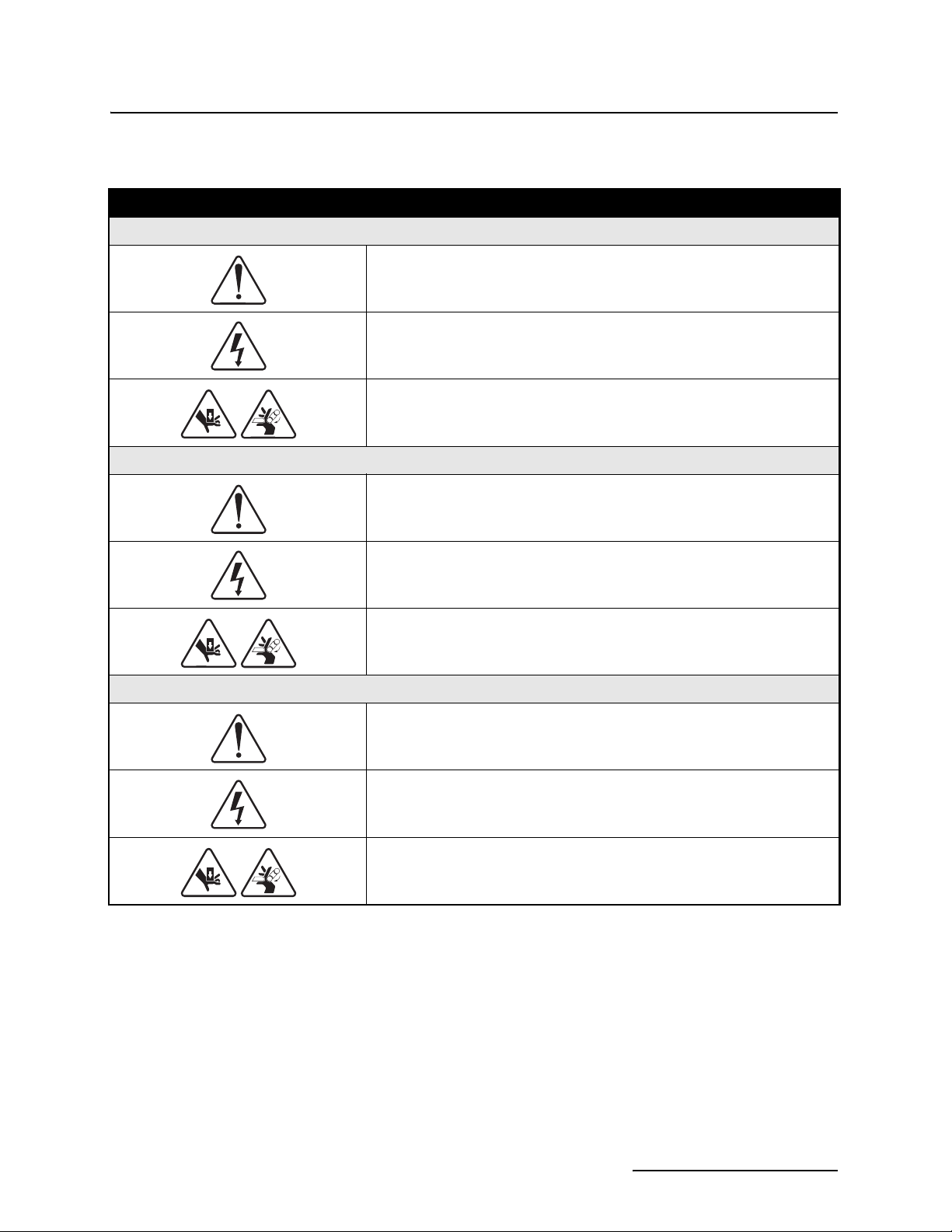
Hazard Symbols The equipment and this manual use symbols used to warn of
hazards. The symbols are explained below.
Hazard Symbols
Warnings and Cautions
The exclamation point within the triangle is a warning sign alerting you of
important instructions in the instrument’s technical reference manual.
The lightning flash and arrowhead within the triangle is a warning sign alerting you of “dangerous voltage” inside the product.
Pinch point. These symbols warn you that your fingers or hands will be seriously injured if you place them between the moving parts of the mechanism
near these symbols.
Symboles de sécurité
Ce symbole signale l’existence d’instructions importantes relatives au produit dans ce manuel.
Safety
Warnungen und Vorsichtshinweise
Ce symbole signale la présence d’un danger d’électocution.
Risque de pincement. Ces symboles vous avertit que les mains ou les
doigts seront blessés sérieusement si vous les mettez entre les éléments
en mouvement du mécanisme près de ces symboles
Das Ausrufezeichen in Dreieck ist ein Warnzeichen, das Sie darauf
aufmerksam macht, daß wichtige Anleitungen zu diesem Handbuch
gehören.
Der gepfeilte Blitz im Dreieck ist ein Warnzeichen, das Sei vor “gefährlichen
Spannungen” im Inneren des Produkts warnt.
Vorsicht Quetschgefahr! Dieses Symbol warnt vor einer unmittelbar drohenden Verletzungsgefahr für Finger und Hände, wenn diese zwischen die
beweglichen Teile des gekennzeichneten Gerätes geraten.
v
Page 8

6712FR Refrigerated Sampler
Safety
vi
Page 9

6712FR Refrigerated Sampler
Table of Contents
Section 1 Introduction
1.1 About This Manual . . . . . . . . . . . . . . . . . . . . . . . . . . . . . . . . . . . . . . . . . . . . . . . . . . 1-1
1.2 About 700 Series Modules. . . . . . . . . . . . . . . . . . . . . . . . . . . . . . . . . . . . . . . . . . . . . 1-2
1.3 SDI-12 Sondes . . . . . . . . . . . . . . . . . . . . . . . . . . . . . . . . . . . . . . . . . . . . . . . . . . . . . . 1-2
1.4 Memory to Store Monitoring Data . . . . . . . . . . . . . . . . . . . . . . . . . . . . . . . . . . . . . . 1-2
1.5 Pump Requirements . . . . . . . . . . . . . . . . . . . . . . . . . . . . . . . . . . . . . . . . . . . . . . . . . 1-3
Section 2 Installation/Preparation
2.1 Preparing the Sampler . . . . . . . . . . . . . . . . . . . . . . . . . . . . . . . . . . . . . . . . . . . . . . . 2-1
2.1.1 Installing the Distributor Shaft Extension . . . . . . . . . . . . . . . . . . . . . . . . . 2-1
2.1.2 Mounting the Controller . . . . . . . . . . . . . . . . . . . . . . . . . . . . . . . . . . . . . . . . 2-1
2.1.3 Installing the Distributor Arm and Discharge Tube . . . . . . . . . . . . . . . . . . 2-2
2.2 Installing Bottle Kits . . . . . . . . . . . . . . . . . . . . . . . . . . . . . . . . . . . . . . . . . . . . . . . . 2-4
2.2.1 Installing Racks . . . . . . . . . . . . . . . . . . . . . . . . . . . . . . . . . . . . . . . . . . . . . . . 2-4
2.2.2 Removing Racks . . . . . . . . . . . . . . . . . . . . . . . . . . . . . . . . . . . . . . . . . . . . . . . 2-6
2.2.3 Installing Composite Bottles . . . . . . . . . . . . . . . . . . . . . . . . . . . . . . . . . . . . . 2-6
2.3 Suction Line. . . . . . . . . . . . . . . . . . . . . . . . . . . . . . . . . . . . . . . . . . . . . . . . . . . . . . . . 2-6
2.3.1 Guidelines for Measuring and Cutting the Suction Line . . . . . . . . . . . . . . 2-7
2.3.2 Attaching Suction Line to Pump Tube . . . . . . . . . . . . . . . . . . . . . . . . . . . . . 2-7
2.4 Strainers . . . . . . . . . . . . . . . . . . . . . . . . . . . . . . . . . . . . . . . . . . . . . . . . . . . . . . . . . . 2-8
2.4.1 Alternative to Strainers . . . . . . . . . . . . . . . . . . . . . . . . . . . . . . . . . . . . . . . . . 2-8
2.5 How Does the Sampler Work? . . . . . . . . . . . . . . . . . . . . . . . . . . . . . . . . . . . . . . . . . 2-9
2.5.1 Measuring Sample Volume . . . . . . . . . . . . . . . . . . . . . . . . . . . . . . . . . . . . . 2-10
2.6 Installing the Sampler . . . . . . . . . . . . . . . . . . . . . . . . . . . . . . . . . . . . . . . . . . . . . . 2-10
2.6.1 Tips for Routing Suction Line . . . . . . . . . . . . . . . . . . . . . . . . . . . . . . . . . . . 2-10
2.6.2 Intake Placement . . . . . . . . . . . . . . . . . . . . . . . . . . . . . . . . . . . . . . . . . . . . . 2-11
2.6.3 Positioning a Sampler . . . . . . . . . . . . . . . . . . . . . . . . . . . . . . . . . . . . . . . . . 2-11
2.7 Connecting External Instruments . . . . . . . . . . . . . . . . . . . . . . . . . . . . . . . . . . . . . 2-11
2.7.1 Flow Meter . . . . . . . . . . . . . . . . . . . . . . . . . . . . . . . . . . . . . . . . . . . . . . . . . . 2-11
2.7.2 Rain Gauge Connector . . . . . . . . . . . . . . . . . . . . . . . . . . . . . . . . . . . . . . . . . 2-11
2.8 Locking the Sampler . . . . . . . . . . . . . . . . . . . . . . . . . . . . . . . . . . . . . . . . . . . . . . . . 2-14
2.9 Servicing the Sampler. . . . . . . . . . . . . . . . . . . . . . . . . . . . . . . . . . . . . . . . . . . . . . . 2-14
Section 3 Programming Introduction
3.1 Initial Operation . . . . . . . . . . . . . . . . . . . . . . . . . . . . . . . . . . . . . . . . . . . . . . . . . . . . 3-1
3.1.1 Selecting a Language . . . . . . . . . . . . . . . . . . . . . . . . . . . . . . . . . . . . . . . . . . . 3-3
3.2 Using Menus and Entering Numbers . . . . . . . . . . . . . . . . . . . . . . . . . . . . . . . . . . . 3-3
3.2.1 Selecting Menu Options . . . . . . . . . . . . . . . . . . . . . . . . . . . . . . . . . . . . . . . . 3-3
3.2.2 Entering Numbers . . . . . . . . . . . . . . . . . . . . . . . . . . . . . . . . . . . . . . . . . . . . . 3-3
3.3 Quick View Screens. . . . . . . . . . . . . . . . . . . . . . . . . . . . . . . . . . . . . . . . . . . . . . . . . . 3-4
3.3.1 Paging Through Quick View Screens . . . . . . . . . . . . . . . . . . . . . . . . . . . . . . 3-4
3.3.2 Changing Settings in a Quick View Screen . . . . . . . . . . . . . . . . . . . . . . . . . 3-4
3.4 Clock and Calendar. . . . . . . . . . . . . . . . . . . . . . . . . . . . . . . . . . . . . . . . . . . . . . . . . . 3-5
3.4.1 Setting the Clock and Calendar . . . . . . . . . . . . . . . . . . . . . . . . . . . . . . . . . . 3-6
3.4.2 Menu Screens: Clock Start Times . . . . . . . . . . . . . . . . . . . . . . . . . . . . . . . . . 3-6
3.5 Menu Screens: Site Descriptions and Program Names . . . . . . . . . . . . . . . . . . . . . 3-7
3.6 Messages . . . . . . . . . . . . . . . . . . . . . . . . . . . . . . . . . . . . . . . . . . . . . . . . . . . . . . . . . . 3-8
3.6.1 Information Messages . . . . . . . . . . . . . . . . . . . . . . . . . . . . . . . . . . . . . . . . . . 3-9
i
Page 10

6712FR Refrigerated Sampler
Table of Contents
3.6.2 Help Notes . . . . . . . . . . . . . . . . . . . . . . . . . . . . . . . . . . . . . . . . . . . . . . . . . . . 3-9
3.6.3 Warning Messages . . . . . . . . . . . . . . . . . . . . . . . . . . . . . . . . . . . . . . . . . . . . 3-10
3.6.4 Operation Messages . . . . . . . . . . . . . . . . . . . . . . . . . . . . . . . . . . . . . . . . . . . 3-10
3.7 Menu Trees . . . . . . . . . . . . . . . . . . . . . . . . . . . . . . . . . . . . . . . . . . . . . . . . . . . . . . . 3-10
Section 4 Standard Programming
4.1 Switching Between Standard and Extended Modes . . . . . . . . . . . . . . . . . . . . . . . . 4-1
4.2 Language Selection, Units of Length . . . . . . . . . . . . . . . . . . . . . . . . . . . . . . . . . . . . 4-1
4.3 Programming Examples . . . . . . . . . . . . . . . . . . . . . . . . . . . . . . . . . . . . . . . . . . . . . . 4-2
4.4 Pacing. . . . . . . . . . . . . . . . . . . . . . . . . . . . . . . . . . . . . . . . . . . . . . . . . . . . . . . . . . . . . 4-5
4.4.1 Trigger Pacing . . . . . . . . . . . . . . . . . . . . . . . . . . . . . . . . . . . . . . . . . . . . . . . . 4-5
4.5 Distribution . . . . . . . . . . . . . . . . . . . . . . . . . . . . . . . . . . . . . . . . . . . . . . . . . . . . . . . . 4-6
4.5.1 Sequential . . . . . . . . . . . . . . . . . . . . . . . . . . . . . . . . . . . . . . . . . . . . . . . . . . . 4-6
4.5.2 Bottles Per Sample . . . . . . . . . . . . . . . . . . . . . . . . . . . . . . . . . . . . . . . . . . . . 4-6
4.5.3 Samples Per Bottle . . . . . . . . . . . . . . . . . . . . . . . . . . . . . . . . . . . . . . . . . . . . 4-6
4.5.4 Composite . . . . . . . . . . . . . . . . . . . . . . . . . . . . . . . . . . . . . . . . . . . . . . . . . . . . 4-6
4.5.5 Continuous Sampling . . . . . . . . . . . . . . . . . . . . . . . . . . . . . . . . . . . . . . . . . . 4-6
4.6 Start Times . . . . . . . . . . . . . . . . . . . . . . . . . . . . . . . . . . . . . . . . . . . . . . . . . . . . . . . . 4-8
4.6.1 How Do Start Times Work? . . . . . . . . . . . . . . . . . . . . . . . . . . . . . . . . . . . . . . 4-8
4.6.2 Sampler Enable/Disable . . . . . . . . . . . . . . . . . . . . . . . . . . . . . . . . . . . . . . . . 4-9
4.7 Running Programs . . . . . . . . . . . . . . . . . . . . . . . . . . . . . . . . . . . . . . . . . . . . . . . . . 4-10
4.7.1 Run Time Screens . . . . . . . . . . . . . . . . . . . . . . . . . . . . . . . . . . . . . . . . . . . . 4-10
4.7.2 Module Readings . . . . . . . . . . . . . . . . . . . . . . . . . . . . . . . . . . . . . . . . . . . . . 4-11
4.8 Interrupting a Running Program. . . . . . . . . . . . . . . . . . . . . . . . . . . . . . . . . . . . . . 4-12
4.8.1 Stop Program . . . . . . . . . . . . . . . . . . . . . . . . . . . . . . . . . . . . . . . . . . . . . . . . 4-12
4.8.2 Resume Program . . . . . . . . . . . . . . . . . . . . . . . . . . . . . . . . . . . . . . . . . . . . . 4-12
4.8.3 View Data . . . . . . . . . . . . . . . . . . . . . . . . . . . . . . . . . . . . . . . . . . . . . . . . . . . 4-13
4.8.4 Grab Sample . . . . . . . . . . . . . . . . . . . . . . . . . . . . . . . . . . . . . . . . . . . . . . . . 4-13
4.8.5 Pump Tube Alarm . . . . . . . . . . . . . . . . . . . . . . . . . . . . . . . . . . . . . . . . . . . . 4-13
4.8.6 Calibrate Volume . . . . . . . . . . . . . . . . . . . . . . . . . . . . . . . . . . . . . . . . . . . . . 4-13
4.8.7 Cal/Adj Parameters . . . . . . . . . . . . . . . . . . . . . . . . . . . . . . . . . . . . . . . . . . . 4-13
4.8.8 Adjust Pacing . . . . . . . . . . . . . . . . . . . . . . . . . . . . . . . . . . . . . . . . . . . . . . . . 4-13
4.8.9 Adjust Volume . . . . . . . . . . . . . . . . . . . . . . . . . . . . . . . . . . . . . . . . . . . . . . . 4-14
4.8.10 Power Used . . . . . . . . . . . . . . . . . . . . . . . . . . . . . . . . . . . . . . . . . . . . . . . . 4-14
4.9 Other Functions . . . . . . . . . . . . . . . . . . . . . . . . . . . . . . . . . . . . . . . . . . . . . . . . . . . 4-14
4.10 Manual Functions . . . . . . . . . . . . . . . . . . . . . . . . . . . . . . . . . . . . . . . . . . . . . . . . . 4-14
4.11 Grab Samples . . . . . . . . . . . . . . . . . . . . . . . . . . . . . . . . . . . . . . . . . . . . . . . . . . . . 4-14
4.12 Calibrate Volume . . . . . . . . . . . . . . . . . . . . . . . . . . . . . . . . . . . . . . . . . . . . . . . . . 4-15
4.12.1 Calibration Tips . . . . . . . . . . . . . . . . . . . . . . . . . . . . . . . . . . . . . . . . . . . . . 4-16
4.13 Operating the Pump . . . . . . . . . . . . . . . . . . . . . . . . . . . . . . . . . . . . . . . . . . . . . . . 4-17
4.14 Moving the Distributor Arm. . . . . . . . . . . . . . . . . . . . . . . . . . . . . . . . . . . . . . . . . 4-17
4.15 Reports. . . . . . . . . . . . . . . . . . . . . . . . . . . . . . . . . . . . . . . . . . . . . . . . . . . . . . . . . . 4-18
4.15.1 Collecting Reports . . . . . . . . . . . . . . . . . . . . . . . . . . . . . . . . . . . . . . . . . . . 4-18
4.15.2 Viewing the Data . . . . . . . . . . . . . . . . . . . . . . . . . . . . . . . . . . . . . . . . . . . . 4-18
4.15.3 Configuring Reports . . . . . . . . . . . . . . . . . . . . . . . . . . . . . . . . . . . . . . . . . . 4-19
4.15.4 Sampling Results Report . . . . . . . . . . . . . . . . . . . . . . . . . . . . . . . . . . . . . . 4-20
4.15.5 Combined Results Report . . . . . . . . . . . . . . . . . . . . . . . . . . . . . . . . . . . . . 4-20
4.15.6 Summary Report . . . . . . . . . . . . . . . . . . . . . . . . . . . . . . . . . . . . . . . . . . . . 4-20
4.16 System IDs. . . . . . . . . . . . . . . . . . . . . . . . . . . . . . . . . . . . . . . . . . . . . . . . . . . . . . . 4-28
4.17 Programming for 700 Series Modules . . . . . . . . . . . . . . . . . . . . . . . . . . . . . . . . . 4-28
Section 5 Extended Programming
5.1 Extended and Standard Mode . . . . . . . . . . . . . . . . . . . . . . . . . . . . . . . . . . . . . . . . . 5-1
5.2 One-Part and Two-Part Programs . . . . . . . . . . . . . . . . . . . . . . . . . . . . . . . . . . . . . . 5-1
5.3 Storage for Extended Programs . . . . . . . . . . . . . . . . . . . . . . . . . . . . . . . . . . . . . . . . 5-2
5.3.1 Selecting a Stored Program . . . . . . . . . . . . . . . . . . . . . . . . . . . . . . . . . . . . . . 5-2
ii
Page 11

6712FR Refrigerated Sampler
Table of Contents
5.4 Programming for 700 Series Modules . . . . . . . . . . . . . . . . . . . . . . . . . . . . . . . . . . . 5-4
5.5 Programming SDI-12 Sondes . . . . . . . . . . . . . . . . . . . . . . . . . . . . . . . . . . . . . . . . . . 5-4
5.6 Programming Examples . . . . . . . . . . . . . . . . . . . . . . . . . . . . . . . . . . . . . . . . . . . . . . 5-4
5.6.1 Storm Water Runoff Sampling . . . . . . . . . . . . . . . . . . . . . . . . . . . . . . . . . . . 5-5
5.7 Suction Head . . . . . . . . . . . . . . . . . . . . . . . . . . . . . . . . . . . . . . . . . . . . . . . . . . . . . . 5-12
5.8 Rinses and Retries. . . . . . . . . . . . . . . . . . . . . . . . . . . . . . . . . . . . . . . . . . . . . . . . . . 5-12
5.9 Pacing. . . . . . . . . . . . . . . . . . . . . . . . . . . . . . . . . . . . . . . . . . . . . . . . . . . . . . . . . . . . 5-12
5.9.1 Event Pacing . . . . . . . . . . . . . . . . . . . . . . . . . . . . . . . . . . . . . . . . . . . . . . . . 5-12
5.9.2 Event Paced Sampling . . . . . . . . . . . . . . . . . . . . . . . . . . . . . . . . . . . . . . . . . 5-13
5.9.3 Nonuniform Time Pacing . . . . . . . . . . . . . . . . . . . . . . . . . . . . . . . . . . . . . . 5-15
5.9.4 Nonuniform Clock Time Pacing . . . . . . . . . . . . . . . . . . . . . . . . . . . . . . . . . 5-15
5.9.5 Nonuniform Interval Pacing . . . . . . . . . . . . . . . . . . . . . . . . . . . . . . . . . . . . 5-15
5.9.6 Random Interval Pacing . . . . . . . . . . . . . . . . . . . . . . . . . . . . . . . . . . . . . . . 5-15
5.10 Distribution . . . . . . . . . . . . . . . . . . . . . . . . . . . . . . . . . . . . . . . . . . . . . . . . . . . . . . 5-16
5.10.1 Sequential . . . . . . . . . . . . . . . . . . . . . . . . . . . . . . . . . . . . . . . . . . . . . . . . . 5-16
5.10.2 Bottles Per Sample . . . . . . . . . . . . . . . . . . . . . . . . . . . . . . . . . . . . . . . . . . 5-16
5.10.3 Samples Per Bottle . . . . . . . . . . . . . . . . . . . . . . . . . . . . . . . . . . . . . . . . . . 5-16
5.10.4 Composite . . . . . . . . . . . . . . . . . . . . . . . . . . . . . . . . . . . . . . . . . . . . . . . . . . 5-16
5.10.5 Multiple Bottle Compositing . . . . . . . . . . . . . . . . . . . . . . . . . . . . . . . . . . . 5-16
5.10.6 Time Switching . . . . . . . . . . . . . . . . . . . . . . . . . . . . . . . . . . . . . . . . . . . . . 5-16
5.10.7 Continuous Sampling . . . . . . . . . . . . . . . . . . . . . . . . . . . . . . . . . . . . . . . . 5-17
5.11 Flow Proportional Sample Volumes. . . . . . . . . . . . . . . . . . . . . . . . . . . . . . . . . . . 5-19
5.11.1 Calculating Variable Sample Volume Settings . . . . . . . . . . . . . . . . . . . . 5-20
5.11.2 Calculations when Using an External Flow Meter . . . . . . . . . . . . . . . . . 5-21
5.11.3 Calculations when Using a 700 Series Flow Module . . . . . . . . . . . . . . . . 5-22
5.12 Sampler Enable. . . . . . . . . . . . . . . . . . . . . . . . . . . . . . . . . . . . . . . . . . . . . . . . . . . 5-22
5.12.1 Sampler Enable . . . . . . . . . . . . . . . . . . . . . . . . . . . . . . . . . . . . . . . . . . . . . 5-24
5.13 Sampler Enable Responses. . . . . . . . . . . . . . . . . . . . . . . . . . . . . . . . . . . . . . . . . . 5-25
5.13.1 Once Enabled Stay Enabled . . . . . . . . . . . . . . . . . . . . . . . . . . . . . . . . . . . 5-25
5.13.2 Repeatable Enable . . . . . . . . . . . . . . . . . . . . . . . . . . . . . . . . . . . . . . . . . . . 5-25
5.13.3 Sample at Enable or Disable . . . . . . . . . . . . . . . . . . . . . . . . . . . . . . . . . . . 5-25
5.13.4 Delay To Start Of Sampling . . . . . . . . . . . . . . . . . . . . . . . . . . . . . . . . . . . 5-26
5.13.5 “Dry Period” Option . . . . . . . . . . . . . . . . . . . . . . . . . . . . . . . . . . . . . . . . . . 5-26
5.13.6 Resetting the Sample Interval at Enable . . . . . . . . . . . . . . . . . . . . . . . . . 5-26
5.14 Pauses/Resumes . . . . . . . . . . . . . . . . . . . . . . . . . . . . . . . . . . . . . . . . . . . . . . . . . . 5-27
5.15 Running Programs . . . . . . . . . . . . . . . . . . . . . . . . . . . . . . . . . . . . . . . . . . . . . . . . 5-27
5.15.1 Run Time Screens . . . . . . . . . . . . . . . . . . . . . . . . . . . . . . . . . . . . . . . . . . . 5-27
5.15.2 Interrupting a Running Program . . . . . . . . . . . . . . . . . . . . . . . . . . . . . . . 5-27
5.16 Sampling Reports . . . . . . . . . . . . . . . . . . . . . . . . . . . . . . . . . . . . . . . . . . . . . . . . . 5-28
5.17 Other Functions . . . . . . . . . . . . . . . . . . . . . . . . . . . . . . . . . . . . . . . . . . . . . . . . . . 5-28
5.18 Software Options. . . . . . . . . . . . . . . . . . . . . . . . . . . . . . . . . . . . . . . . . . . . . . . . . . 5-28
5.18.1 Liquid Detector Enable/Disable . . . . . . . . . . . . . . . . . . . . . . . . . . . . . . . . 5-28
5.18.2 Programming Style . . . . . . . . . . . . . . . . . . . . . . . . . . . . . . . . . . . . . . . . . . 5-29
5.18.3 Measurement Interval . . . . . . . . . . . . . . . . . . . . . . . . . . . . . . . . . . . . . . . . 5-29
5.18.4 Dual Sampler Mode . . . . . . . . . . . . . . . . . . . . . . . . . . . . . . . . . . . . . . . . . . 5-29
5.18.5 Pre-sample and Post-sample Purge Counts . . . . . . . . . . . . . . . . . . . . . . . 5-31
5.18.6 Serial Output . . . . . . . . . . . . . . . . . . . . . . . . . . . . . . . . . . . . . . . . . . . . . . . 5-32
5.18.7 Program Lock . . . . . . . . . . . . . . . . . . . . . . . . . . . . . . . . . . . . . . . . . . . . . . . 5-34
5.19 Hardware Setup . . . . . . . . . . . . . . . . . . . . . . . . . . . . . . . . . . . . . . . . . . . . . . . . . . 5-36
5.19.1 SDI-12 Sonde Setup . . . . . . . . . . . . . . . . . . . . . . . . . . . . . . . . . . . . . . . . . . 5-36
5.19.2 Rain Gauge Setup . . . . . . . . . . . . . . . . . . . . . . . . . . . . . . . . . . . . . . . . . . . 5-36
5.19.3 I/O Pin Programming . . . . . . . . . . . . . . . . . . . . . . . . . . . . . . . . . . . . . . . . 5-37
5.19.4 Dialout Alarms . . . . . . . . . . . . . . . . . . . . . . . . . . . . . . . . . . . . . . . . . . . . . . 5-39
5.19.5 Pager Numbers . . . . . . . . . . . . . . . . . . . . . . . . . . . . . . . . . . . . . . . . . . . . . 5-40
5.19.6 Digital Modem Text Messaging . . . . . . . . . . . . . . . . . . . . . . . . . . . . . . . . 5-40
5.19.7 Refrigerator Temperature . . . . . . . . . . . . . . . . . . . . . . . . . . . . . . . . . . . . . 5-41
5.19.8 Analog Output . . . . . . . . . . . . . . . . . . . . . . . . . . . . . . . . . . . . . . . . . . . . . . 5-41
5.20 Memory . . . . . . . . . . . . . . . . . . . . . . . . . . . . . . . . . . . . . . . . . . . . . . . . . . . . . . . . . 5-42
5.21 Pressurized Lines . . . . . . . . . . . . . . . . . . . . . . . . . . . . . . . . . . . . . . . . . . . . . . . . . 5-44
iii
Page 12

6712FR Refrigerated Sampler
Table of Contents
5.22 Command Driven Operation. . . . . . . . . . . . . . . . . . . . . . . . . . . . . . . . . . . . . . . . . 5-44
5.23 Command Driven Sampler Responses. . . . . . . . . . . . . . . . . . . . . . . . . . . . . . . . . 5-45
Section 6 SDI-12 Sondes
6.1 SDI-12 Data Parameters . . . . . . . . . . . . . . . . . . . . . . . . . . . . . . . . . . . . . . . . . . . . . 6-1
6.2 Scanning For Sondes. . . . . . . . . . . . . . . . . . . . . . . . . . . . . . . . . . . . . . . . . . . . . . . . . 6-2
6.3 Isco Ready Sondes . . . . . . . . . . . . . . . . . . . . . . . . . . . . . . . . . . . . . . . . . . . . . . . . . . . 6-3
6.4 Other SDI-12 Sondes. . . . . . . . . . . . . . . . . . . . . . . . . . . . . . . . . . . . . . . . . . . . . . . . . 6-3
6.5 Sonde Setup - Storing Parameter Data . . . . . . . . . . . . . . . . . . . . . . . . . . . . . . . . . . 6-4
6.6 Sonde Calibration and Validation . . . . . . . . . . . . . . . . . . . . . . . . . . . . . . . . . . . . . . 6-5
6.6.1 The Calibration Screens . . . . . . . . . . . . . . . . . . . . . . . . . . . . . . . . . . . . . . . . 6-6
6.6.2 The Validation Screen . . . . . . . . . . . . . . . . . . . . . . . . . . . . . . . . . . . . . . . . . . 6-6
6.7 Disconnecting Sondes . . . . . . . . . . . . . . . . . . . . . . . . . . . . . . . . . . . . . . . . . . . . . . . . 6-7
Section 7 Remote Operation
7.1 Computer Operation . . . . . . . . . . . . . . . . . . . . . . . . . . . . . . . . . . . . . . . . . . . . . . . . . 7-1
7.1.1 Menu Control . . . . . . . . . . . . . . . . . . . . . . . . . . . . . . . . . . . . . . . . . . . . . . . . . 7-2
7.1.2 External Program Control . . . . . . . . . . . . . . . . . . . . . . . . . . . . . . . . . . . . . . . 7-4
7.1.3 Remote Control of Sampler Keypad . . . . . . . . . . . . . . . . . . . . . . . . . . . . . . . 7-8
7.2 Telephone Commands . . . . . . . . . . . . . . . . . . . . . . . . . . . . . . . . . . . . . . . . . . . . . . . 7-9
Section 8 Maintenance
8.1 Maintenance Checklist . . . . . . . . . . . . . . . . . . . . . . . . . . . . . . . . . . . . . . . . . . . . . . . 8-1
8.2 Cleaning Guidelines . . . . . . . . . . . . . . . . . . . . . . . . . . . . . . . . . . . . . . . . . . . . . . . . . 8-1
8.2.1 Refrigerator . . . . . . . . . . . . . . . . . . . . . . . . . . . . . . . . . . . . . . . . . . . . . . . . . . 8-1
8.2.2 Controller . . . . . . . . . . . . . . . . . . . . . . . . . . . . . . . . . . . . . . . . . . . . . . . . . . . . 8-2
8.2.3 Sample Bottles . . . . . . . . . . . . . . . . . . . . . . . . . . . . . . . . . . . . . . . . . . . . . . . . 8-2
8.2.4 Suction Line, Pump Tube, and Discharge Tube . . . . . . . . . . . . . . . . . . . . . . 8-2
8.2.5 Strainer . . . . . . . . . . . . . . . . . . . . . . . . . . . . . . . . . . . . . . . . . . . . . . . . . . . . . 8-2
8.2.6 Air Filter . . . . . . . . . . . . . . . . . . . . . . . . . . . . . . . . . . . . . . . . . . . . . . . . . . . . . 8-2
8.2.7 Condenser . . . . . . . . . . . . . . . . . . . . . . . . . . . . . . . . . . . . . . . . . . . . . . . . . . . . 8-2
8.3 Cleaning Protocols for Priority Pollutants. . . . . . . . . . . . . . . . . . . . . . . . . . . . . . . . 8-3
8.3.1 Isco Glass Sample Bottles . . . . . . . . . . . . . . . . . . . . . . . . . . . . . . . . . . . . . . . 8-3
8.3.2 Vinyl Suction Line . . . . . . . . . . . . . . . . . . . . . . . . . . . . . . . . . . . . . . . . . . . . . 8-3
8.3.3 PTFE Suction Line . . . . . . . . . . . . . . . . . . . . . . . . . . . . . . . . . . . . . . . . . . . . 8-3
8.3.4 Isco Pump Tube . . . . . . . . . . . . . . . . . . . . . . . . . . . . . . . . . . . . . . . . . . . . . . . 8-3
8.4 Maintenance Screens . . . . . . . . . . . . . . . . . . . . . . . . . . . . . . . . . . . . . . . . . . . . . . . . 8-4
8.4.1 Set Clock . . . . . . . . . . . . . . . . . . . . . . . . . . . . . . . . . . . . . . . . . . . . . . . . . . . . . 8-4
8.4.2 Pump Tube Alarm . . . . . . . . . . . . . . . . . . . . . . . . . . . . . . . . . . . . . . . . . . . . . 8-5
8.4.3 Internal Battery Warning . . . . . . . . . . . . . . . . . . . . . . . . . . . . . . . . . . . . . . . 8-6
8.4.4 Diagnostics . . . . . . . . . . . . . . . . . . . . . . . . . . . . . . . . . . . . . . . . . . . . . . . . . . . 8-7
8.5 Replacing the Pump Tube. . . . . . . . . . . . . . . . . . . . . . . . . . . . . . . . . . . . . . . . . . . . . 8-9
8.5.1 Checklist For Replacing Pump Tube . . . . . . . . . . . . . . . . . . . . . . . . . . . . . 8-10
8.6 Opening the Controller Case . . . . . . . . . . . . . . . . . . . . . . . . . . . . . . . . . . . . . . . . . 8-12
8.7 Replacing the Desiccant . . . . . . . . . . . . . . . . . . . . . . . . . . . . . . . . . . . . . . . . . . . . . 8-12
8.8 Replacing the Internal Battery . . . . . . . . . . . . . . . . . . . . . . . . . . . . . . . . . . . . . . . 8-14
8.9 Error Messages . . . . . . . . . . . . . . . . . . . . . . . . . . . . . . . . . . . . . . . . . . . . . . . . . . . . 8-16
8.10 Pump Tube Warning. . . . . . . . . . . . . . . . . . . . . . . . . . . . . . . . . . . . . . . . . . . . . . . 8-16
8.11 Servicing the Refrigerator . . . . . . . . . . . . . . . . . . . . . . . . . . . . . . . . . . . . . . . . . . 8-17
8.11.1 Electrical System . . . . . . . . . . . . . . . . . . . . . . . . . . . . . . . . . . . . . . . . . . . . 8-17
8.11.2 Refrigeration System . . . . . . . . . . . . . . . . . . . . . . . . . . . . . . . . . . . . . . . . . 8-20
Appendix A Menu Flowcharts
iv
Page 13

6712FR Refrigerated Sampler
Table of Contents
Appendix B Material Safety Data Sheets
Appendix C General Safety Procedures
C.1 Practical Safety Precautions . . . . . . . . . . . . . . . . . . . . . . . . . . . . . . . . . . . . . . . . . . C-1
C.1.1 Hazards . . . . . . . . . . . . . . . . . . . . . . . . . . . . . . . . . . . . . . . . . . . . . . . . . . . . . C-1
C.1.2 Planning . . . . . . . . . . . . . . . . . . . . . . . . . . . . . . . . . . . . . . . . . . . . . . . . . . . . . C-2
C.1.3 Adverse Atmospheres . . . . . . . . . . . . . . . . . . . . . . . . . . . . . . . . . . . . . . . . . . C-2
C.1.4 Entering Manholes . . . . . . . . . . . . . . . . . . . . . . . . . . . . . . . . . . . . . . . . . . . . C-2
C.1.5 Traffic Protection . . . . . . . . . . . . . . . . . . . . . . . . . . . . . . . . . . . . . . . . . . . . . . C-3
C.1.6 Falling Objects . . . . . . . . . . . . . . . . . . . . . . . . . . . . . . . . . . . . . . . . . . . . . . . C-3
C.1.7 Removing the Covers . . . . . . . . . . . . . . . . . . . . . . . . . . . . . . . . . . . . . . . . . . C-3
C.1.8 Other Precautions . . . . . . . . . . . . . . . . . . . . . . . . . . . . . . . . . . . . . . . . . . . . . C-3
C.1.9 Emergencies . . . . . . . . . . . . . . . . . . . . . . . . . . . . . . . . . . . . . . . . . . . . . . . . . C-4
C.1.10 Field Equipment . . . . . . . . . . . . . . . . . . . . . . . . . . . . . . . . . . . . . . . . . . . . . C-4
C.2 Lethal Atmospheres in Sewers . . . . . . . . . . . . . . . . . . . . . . . . . . . . . . . . . . . . . . . . C-4
C.3 Hazardous Gases . . . . . . . . . . . . . . . . . . . . . . . . . . . . . . . . . . . . . . . . . . . . . . . . . . . C-6
Appendix D Replacement Parts List
D.1 Replacement Parts Diagrams and Listings . . . . . . . . . . . . . . . . . . . . . . . . . . . . . . D-1
Appendix E Accessories List
E.1 Order Information . . . . . . . . . . . . . . . . . . . . . . . . . . . . . . . . . . . . . . . . . . . . . . . . . . E-1
E.2 Samplers . . . . . . . . . . . . . . . . . . . . . . . . . . . . . . . . . . . . . . . . . . . . . . . . . . . . . . . . . . E-1
E.3 Bottle Kits . . . . . . . . . . . . . . . . . . . . . . . . . . . . . . . . . . . . . . . . . . . . . . . . . . . . . . . . . E-1
E.4 Bottle Racks, Retaining Rings, Discharge Tubes, Distributor Arm . . . . . . . . . . . E-2
E.5 Bulk Sets of Bottles with Lids . . . . . . . . . . . . . . . . . . . . . . . . . . . . . . . . . . . . . . . . . E-2
E.6 Pump Tubes, Suction Line, Strainers . . . . . . . . . . . . . . . . . . . . . . . . . . . . . . . . . . . E-3
E.7 Data Collection Devices and Cables . . . . . . . . . . . . . . . . . . . . . . . . . . . . . . . . . . . . E-3
E.8 12-Volt Power Sources . . . . . . . . . . . . . . . . . . . . . . . . . . . . . . . . . . . . . . . . . . . . . . . E-4
E.9 Modules, Rain Gauges, & Interfacing Instruments . . . . . . . . . . . . . . . . . . . . . . . . E-4
E.10 SDI-12 Data Acquisition Connect Cables . . . . . . . . . . . . . . . . . . . . . . . . . . . . . . . E-4
List of Illustrations
2-1 Mounting the Controller . . . . . . . . . . . . . . . . . . . . . . . . . . . . . . . . . . . . . . . . . . . . . 2-2
2-2 Installing the Bottle Racks . . . . . . . . . . . . . . . . . . . . . . . . . . . . . . . . . . . . . . . . . . . 2-5
2-3 Installing the 24-bottle, 12-bottle, and 8-bottle Kits . . . . . . . . . . . . . . . . . . . . . . . 2-5
2-4 Installing the 2-bottle Kit . . . . . . . . . . . . . . . . . . . . . . . . . . . . . . . . . . . . . . . . . . . . 2-6
2-5 Attaching the suction line to the pump tubing . . . . . . . . . . . . . . . . . . . . . . . . . . . . 2-7
2-6 Identifying the Sampler Components . . . . . . . . . . . . . . . . . . . . . . . . . . . . . . . . . . . 2-9
3-1 Menu Tree for Standard Programming . . . . . . . . . . . . . . . . . . . . . . . . . . . . . . . . . 3-11
4-1 Sample Distribution . . . . . . . . . . . . . . . . . . . . . . . . . . . . . . . . . . . . . . . . . . . . . . . . . 4-7
4-2 Start Time Diagram . . . . . . . . . . . . . . . . . . . . . . . . . . . . . . . . . . . . . . . . . . . . . . . . 4-10
4-3 Running a Program . . . . . . . . . . . . . . . . . . . . . . . . . . . . . . . . . . . . . . . . . . . . . . . . 4-11
4-4 Taking a Grab Sample . . . . . . . . . . . . . . . . . . . . . . . . . . . . . . . . . . . . . . . . . . . . . 4-15
4-5 Report: Program Settings . . . . . . . . . . . . . . . . . . . . . . . . . . . . . . . . . . . . . . . . . . . 4-23
4-6 Report: Sampling Results . . . . . . . . . . . . . . . . . . . . . . . . . . . . . . . . . . . . . . . . . . . 4-24
4-7 Report: Combined Results . . . . . . . . . . . . . . . . . . . . . . . . . . . . . . . . . . . . . . . . . . . 4-25
4-8 Report: Combined Results (continued) . . . . . . . . . . . . . . . . . . . . . . . . . . . . . . . . . 4-26
4-9 Report: Summary . . . . . . . . . . . . . . . . . . . . . . . . . . . . . . . . . . . . . . . . . . . . . . . . . . 4-27
5-1 Sample Distribution . . . . . . . . . . . . . . . . . . . . . . . . . . . . . . . . . . . . . . . . . . . . . . . . 5-18
5-2 Factors Affecting Flow-Weighted Variable-Volume Samples . . . . . . . . . . . . . . . 5-20
5-3 Variable-Volume Scenario . . . . . . . . . . . . . . . . . . . . . . . . . . . . . . . . . . . . . . . . . . . 5-21
v
Page 14

6712FR Refrigerated Sampler
Table of Contents
5-4 Start Time Diagram for Sampler Enable Settings . . . . . . . . . . . . . . . . . . . . . . . . 5-23
5-5 Event Mark Timing Diagram . . . . . . . . . . . . . . . . . . . . . . . . . . . . . . . . . . . . . . . . 5-31
5-6 Password Protected Functions . . . . . . . . . . . . . . . . . . . . . . . . . . . . . . . . . . . . . . . 5-35
6-1 SDI-12 Sonde Parameters . . . . . . . . . . . . . . . . . . . . . . . . . . . . . . . . . . . . . . . . . . . . 6-2
7-1 Press and hold ?? to connect to the sampler . . . . . . . . . . . . . . . . . . . . . . . . . . . . . . 7-2
7-2 Example list of remote menu commands . . . . . . . . . . . . . . . . . . . . . . . . . . . . . . . . 7-2
8-1 Removing and Replacing the Pump Tube . . . . . . . . . . . . . . . . . . . . . . . . . . . . . . . 8-11
8-2 Placing the Pump Tube in the Liquid Detector . . . . . . . . . . . . . . . . . . . . . . . . . . 8-11
8-3 Opening the Controller . . . . . . . . . . . . . . . . . . . . . . . . . . . . . . . . . . . . . . . . . . . . . 8-13
8-4 Main Circuit Board Connections . . . . . . . . . . . . . . . . . . . . . . . . . . . . . . . . . . . . . . 8-14
8-5 Rear View of the 6712FR . . . . . . . . . . . . . . . . . . . . . . . . . . . . . . . . . . . . . . . . . . . . 8-17
8-6 Thermostat Logic Circuit Board . . . . . . . . . . . . . . . . . . . . . . . . . . . . . . . . . . . . . . 8-18
8-7 Control Box Wiring . . . . . . . . . . . . . . . . . . . . . . . . . . . . . . . . . . . . . . . . . . . . . . . . 8-18
8-8 Control Box Connections . . . . . . . . . . . . . . . . . . . . . . . . . . . . . . . . . . . . . . . . . . . 8-18
8-9 Refrigeration System Schematic . . . . . . . . . . . . . . . . . . . . . . . . . . . . . . . . . . . . . . 8-21
A-1 6712 Menu Tree for Standard Programming . . . . . . . . . . . . . . . . . . . . . . . . . . . . . A-1
A-2 Standard Programming: Programming Screens . . . . . . . . . . . . . . . . . . . . . . . . . . A-2
A-3 Standard and Extended Programming: Start Times . . . . . . . . . . . . . . . . . . . . . . . A-3
A-4 Standard Programming: Quick View; Programming Screens . . . . . . . . . . . . . . . . A-4
A-5 Standard Programming: Quick View; Start Times . . . . . . . . . . . . . . . . . . . . . . . . A-5
A-6 View Report . . . . . . . . . . . . . . . . . . . . . . . . . . . . . . . . . . . . . . . . . . . . . . . . . . . . . . . A-6
A-7 Maintenance Screens . . . . . . . . . . . . . . . . . . . . . . . . . . . . . . . . . . . . . . . . . . . . . . . . A-7
A-8 Manual Functions Screens . . . . . . . . . . . . . . . . . . . . . . . . . . . . . . . . . . . . . . . . . . . A-8
A-9 Extended Programming: Programming Screens . . . . . . . . . . . . . . . . . . . . . . . . . . A-9
A-10 Extended Programming: Equipment Setup . . . . . . . . . . . . . . . . . . . . . . . . . . . A-10
A-11 Extended Programming: Pacing and Distribution . . . . . . . . . . . . . . . . . . . . . . A-11
A-12 Extended Programming: Event Conditions . . . . . . . . . . . . . . . . . . . . . . . . . . . . A-12
A-13 Extended Programming: Programmed Sampler Enable . . . . . . . . . . . . . . . . . A-13
A-14 Extended Programming: Quick View; Programming Screens . . . . . . . . . . . . . A-14
A-15 Extended Programming: Quick View; Equipment Set-Up . . . . . . . . . . . . . . . . A-15
A-16 Extended Programming: Quick View; Pacing and Distribution . . . . . . . . . . . A-16
A-17 Extended Programming: Quick View; Programmed Sampler Enable . . . . . . . A-17
A-18 Extended Programming: Normal View; Software Options . . . . . . . . . . . . . . . . A-18
A-19 Extended Programming: Quick View; Software Options . . . . . . . . . . . . . . . . . A-19
A-20 Extended Programming: Normal View; Hardware . . . . . . . . . . . . . . . . . . . . . . A-20
A-21 Extended Programming: Quick View; Hardware . . . . . . . . . . . . . . . . . . . . . . . A-21
A-22 Analog and Dialout Screens . . . . . . . . . . . . . . . . . . . . . . . . . . . . . . . . . . . . . . . . A-22
A-23 Analog Output and Dialout Quick View Screens . . . . . . . . . . . . . . . . . . . . . . . A-22
A-24 SDI-12 Sonde Screens . . . . . . . . . . . . . . . . . . . . . . . . . . . . . . . . . . . . . . . . . . . . . A-23
List of Tables
1-1 6712FR Sampler Features . . . . . . . . . . . . . . . . . . . . . . . . . . . . . . . . . . . . . . . . . . . . 1-3
1-2 6712FR Sampler Construction Materials . . . . . . . . . . . . . . . . . . . . . . . . . . . . . . . . 1-7
1-3 Technical Specifications for the 6712FR Refrigerated Sampler . . . . . . . . . . . . . . 1-7
1-4 Connector Specifications . . . . . . . . . . . . . . . . . . . . . . . . . . . . . . . . . . . . . . . . . . . . 1-14
2-1 Distributor Arm Positions and Discharge Tube Lengths for Bottle Kits . . . . . . . 2-3
2-2 Selecting the Right Strainer . . . . . . . . . . . . . . . . . . . . . . . . . . . . . . . . . . . . . . . . . . 2-8
2-3 Connecting Isco Instruments to the Sampler . . . . . . . . . . . . . . . . . . . . . . . . . . . . 2-13
3-1 About the Keypad . . . . . . . . . . . . . . . . . . . . . . . . . . . . . . . . . . . . . . . . . . . . . . . . . . . 3-2
4-1 Standard Program: Sample Every 15 Minutes, One Sample Per Bottle . . . . . . . 4-2
4-2 Standard Program: Flow-Paced Sampling, Two Bottles Per Sample . . . . . . . . . . 4-3
4-3 Reports: Program Events, Source Codes, and Error Codes . . . . . . . . . . . . . . . . . 4-21
4-4 Programming Example With 730 Module Installed . . . . . . . . . . . . . . . . . . . . . . . 4-29
4-5 Programming Example With 750 Module Installed . . . . . . . . . . . . . . . . . . . . . . . 4-31
5-1 Selecting a Stored Extended Program . . . . . . . . . . . . . . . . . . . . . . . . . . . . . . . . . . 5-3
5-2 Storm Water Runoff Sampling . . . . . . . . . . . . . . . . . . . . . . . . . . . . . . . . . . . . . . . . 5-6
vi
Page 15

6712FR Refrigerated Sampler
Table of Contents
5-3 Event Paced Sampling . . . . . . . . . . . . . . . . . . . . . . . . . . . . . . . . . . . . . . . . . . . . . . 5-13
5-4 Sampler Enable . . . . . . . . . . . . . . . . . . . . . . . . . . . . . . . . . . . . . . . . . . . . . . . . . . . 5-24
5-5 Serial Data Codes . . . . . . . . . . . . . . . . . . . . . . . . . . . . . . . . . . . . . . . . . . . . . . . . . . 5-33
7-1 6712 Remote Menu Commands . . . . . . . . . . . . . . . . . . . . . . . . . . . . . . . . . . . . . . . . 7-3
7-2 Serial Data Codes . . . . . . . . . . . . . . . . . . . . . . . . . . . . . . . . . . . . . . . . . . . . . . . . . . . 7-6
7-3 Remote Control of Sampler Keypad . . . . . . . . . . . . . . . . . . . . . . . . . . . . . . . . . . . . 7-8
7-4 6712 Remote Phone Commands . . . . . . . . . . . . . . . . . . . . . . . . . . . . . . . . . . . . . . . 7-9
8-1 Setting the Clock and Calendar . . . . . . . . . . . . . . . . . . . . . . . . . . . . . . . . . . . . . . . 8-5
8-2 Resetting the Pump Counter . . . . . . . . . . . . . . . . . . . . . . . . . . . . . . . . . . . . . . . . . . 8-6
8-3 Checking and Replacing the Internal Battery . . . . . . . . . . . . . . . . . . . . . . . . . . . . 8-6
C-1 Hazardous Gases . . . . . . . . . . . . . . . . . . . . . . . . . . . . . . . . . . . . . . . . . . . . . . . . . . . C-6
vii
Page 16

6712FR Refrigerated Sampler
Table of Contents
viii
Page 17
6712FR Refrigerated Sampler
Section 1 Introduction
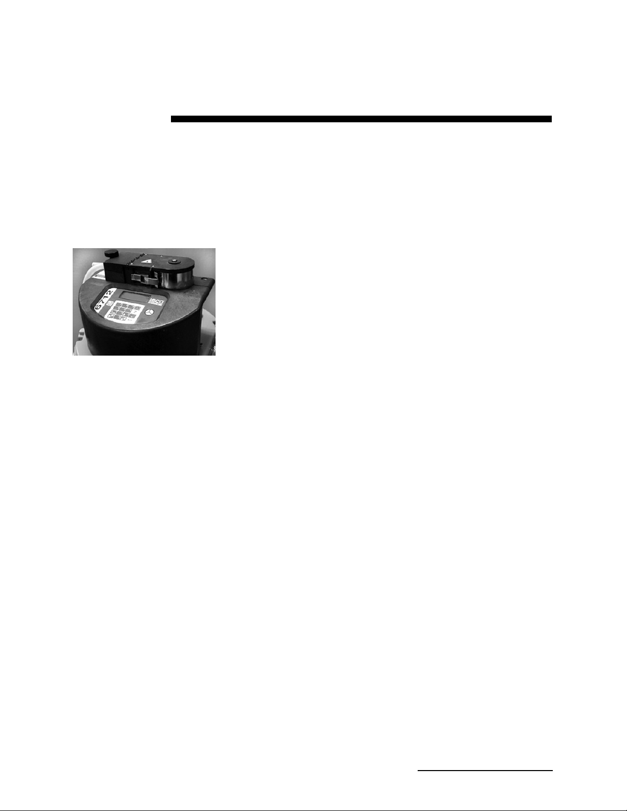
The 6712FR Refrigerated Sampler is an integral part of Teledyne
Isco’s comprehensive sampling system. The system includes the
6712FR and 6712SR Refrigerated Samplers, the 6712 Compact
Sampler, and the 6712 Standard Sampler.
The 6712FR is ideally suited for permanent installation in a wide
variety of indoor and outdoor environments. Constructed from
durable, corrosion resistant materials, the 6712FR withstands
the hostile environments of industrial and municipal monitoring
sites. However, do not install in locations where the refrigerator’s
lower compartment could become submerged.
The 6712FR accepts a variety of sequential and composite bottle
kits. Like all samplers in the 6712 series, it is compatible with a
variety of Isco instruments.
6712 Controller
1.1 About This Manual This manual contains the information you will need to install,
program, operate, and maintain a 6712FR refrigerated sampler.
There are eight sections and five appendices:
• Section 1, Introduction lists the features and specifica-
tions of the 6712FR refrigerated sampler.
• Section 2, Installation/Preparation steps you through
installing the sampler and preparing it for use.
• Section 3, Getting Started describes features that are
common to both standard and extended programming
modes.
• Section 4, Standard Programming shows how to
program your sampler using standard programming
mode.
• Section 5, Extended Programming shows how to
program your sampler using extended programming
mode.
• Section 6, SDI-12 Sondes provides information on
setting up sondes to work with the 6712FR.
• Section 7, Remote Operation explains how the 6712
controller can be operated remotely from external
devices.
• Section 8, Maintenance covers the basic maintenance
required to keep your sampler in top operating
condition.
1-1
Page 18

6712FR Refrigerated Sampler
Section 1 Introduction
The appendices are:
• Appendix A, Menu Flowcharts
• Appendix B, Material Safety Data Sheets
• Appendix C, General Safety Procedures
• Appendix D, Replacement Parts
• Appendix E, Accessories List
1.2 About 700 Series Modules
The bay on the controller’s side accepts any of Teledyne Isco’s 700
Series Modules. The 700 Series includes:
• 701 pH Parameter Module for monitoring pH and
temperature.
• 710 Ultrasonic Module for monitoring a flow stream’s
level and flow rate with an ultrasonic level sensor.
• 720 Submerged Probe Module for monitoring a flow
stream’s level and flow rate with a submerged probe.
• 730 Bubbler Flow Module for monitoring a flow stream’s
level and flow rate with a bubbler system.
• 750 Area Velocity Module for monitoring a flow stream’s
level, velocity, and flow rate.
• 780 4-20mA Input Module for interfacing to non-Isco
devices with 4 to 20 milliampere output signals.
The modules are optional accessories, and are not required for
operation. However, the modules offer a number of advantages:
they are an economical way to combine flow rate or parameter
monitoring with sampling, and you can program the samplers
and modules as a single unit. Finally, the samplers store the
readings in memory.
1.3 SDI-12 Sondes As an option, the sampler accepts up to 16 parameters from up to
ten sensors with SDI-12 addresses from 0 - 9 (refer to SDI-12
Sonde Readings, page 1-10, for specific parameters).
The data parameters used by the sensing device (sonde) and
recording device (sampler) must match. Certain vendors’ sondes
have enhanced commands that facilitate “plug and play” setup.
These Isco Ready sondes can tell the 6712FR what values they
have, their order, and units of measure. Other sondes can be
used, but require manual setup to identify proper data types for
each data value reported.
1.4 Memory to Store Monitoring Data
1-2
The samplers contain enough memory to store five sampling programs, sampling data, Isco 700 Series Module readings, and
SDI-12 parameter readings. You can view the readings on your
sampler’s display.
You can also retrieve the readings and reports so the information
can be processed on a personal computer. Readings and reports
may be collected with a computer running Teledyne Isco’s
Flowlink™ software. Flowlink can download the information
through a direct connection, a modem connection (when the
sampler is equipped with the optional dial-out modem or con-
Page 19
6712FR Refrigerated Sampler
Section 1 Introduction
nected to the optional digital cellular modem), or from a 581
Rapid Transfer Device (RTD). The RTD is a quick and simple
way to transfer the data from the field to your computer. Reports
are easily collected with Teledyne Isco’s Samplink software.
1.5 Pump Requirements The pump also requires a pump tube made specifically for the
6712 and 6700 Series samplers. These pump tubes are easily recognized by their blue alignment collars. The 6712 pump tubing is
the same as that for Teledyne Isco’s 6700 Series samplers, but
different from Teledyne Isco’s earlier model samplers, such as the
3700 Series. Other types of pump tubing will not work in
the 6712FR. Refer to Replacing the Pump Tube on page 8-9.
CAUTION
This sampler has a high performance pump. As with all such
pumps, it relies upon liquid to cool working components. If the
sampler is programmed to pump in the absence of liquid in
excess of 5 minutes, excessive heat buildup may damage the
paddles, rollers, and housing. Ensure that the liquid inlet is
completely immersed.
Top Cover
Controller Only
(does not include refrigerator)
Refrigerator
Table 1-1 6712FR Sampler Features
General Features
• Protects pump, power source, and controller.
• Lockable latches.
• Contains a rechargeable desiccant to prevent moisture damage to the
electronics, pump, and distributor systems.
• Control panel sloped 15 degrees for easy reading.
• Keys labeled with large, vivid icons.
• 80-character display (4 lines by 20 columns).
• Display has selectable backlight:
Always on or always off.
Timed, switching off when keypad is inactive for 60 seconds.
• Memory for program and data storage.
• Flash memory for easy software upgrades.
• NEMA 4X and 6 (IP67) ratings.
• The 6712FR requires 120 volts AC, 60 Hz, or optional 230 volts Ac, 50 Hz. A
built-in 12 volt DC power converter powers the controller.
• The power supply and solid state thermostat are sealed inside the refrigerator’s
base. However, electrical connections for the fan and compressor are not
sealed.
• A forced air condensing coil and front ventilation let you place the unit close to a
wall or in a corner.
• The oversized wrap-around evaporator plate cools the sampling compartment
quickly and efficiently. Heaters on the plate let the sampler continue to operate
in cold temperatures. The evaporator plate is self-defrosting.
• Food-grade ABS plastic interior will not support bacterial growth or leach
plasticizers into the sample.
1-3
Page 20
6712FR Refrigerated Sampler
Section 1 Introduction
Table 1-1 6712FR Sampler Features (Continued)
Adjustable
Distributor Arm
Discharge Tube and Support
Spring
Composite Tube Guide for Composite Sampling
Compatible
Isco Products
Real-Time Displays As the sampler runs a sampling program, it displays the program’s status. The
Programming for Modules Program the modules from the sampler’s control panel. The module’s program
• A single distributor arm adjusts quickly to fit all bottle kits. Easily removed for
composite sampling.
• Routes sample liquid from pump tube, through distributor arm to sample bottle.
• Keeps discharge tube in place over composite bottles.
• 581 Rapid Transfer Device
• 1640 Liquid Level Actuator
• 2100 Series Flow Modules
• 674 Rain Gauge
• 700 Series Modules
• 4100 Series Flow Loggers
• SDI-12 Sondes
• 4200 Series Flow Meters
• Refrigerator Temperature Sensor
• Flowlink, Samplink
status display may include such information as the time of the next sample, the
number of the next bottle, or whether the sampler is disabled or stopped. If the
sampler encounters an error while running the program, it displays a message
alerting you to the problem.
settings become part of the sampling program.
Setup for SDI-12 Sondes Calibrate and program SDI-12 sondes from the sampler’s control panel. The pro-
Memory for Stored Programs
and Readings
Five Reports Available
Serial Data Output
Units of Measure A variety of metric and English units of measure for length, flow rate, flow vol-
External Sampler Enable Isco flow meters and flow loggers have a programmable sampler enable feature
gram settings become part of the sampling program. See Section 6.
512 kilobytes of battery-backed RAM (Random Access Memory), to store:
• Five sampling programs.
• A sampling report from the most recently run program. It records as many as
1000 sampling events; events can be the program start time, enable time,
sample event information, etc.
• 700 Series module readings. The readings can be: level, flow rate, velocity, pH,
temperature, or the data collected by the 4-20 mA module.
• Rain gauge and refrigerator temperature readings.
• SDI-12 sonde readings.
• The Program Settings report, listing current program settings.
• The Sampling Results report, listing the events occurring during the program.
• The Combined Results report, combining sampling events with readings from a
rain gauge, module, or SDI -12 sonde.
• The Module Summary report, summarizing flow rate or parameter readings.
• The Rainfall Summary report, listing a summary of rainfall readings.
• ASCII data output from the interrogator port.
ume, and temperature.
that lets them send an electronic signal to a 6712FR that enables (starts) or disables (stops) a running sampling program.
Dual Sampler Mode Dual Sampler Mode operates two samplers.
1-4
Page 21
6712FR Refrigerated Sampler
Table 1-1 6712FR Sampler Features (Continued)
Section 1 Introduction
Command Driven Operation
Warning Messages
Optional Dialout Modem The 6712 controller can be ordered with a factory-installed 2400 baud dialout
On-Line Help Notes When programming the sampler, press the [?] (Help) key for a brief help note. All
Two Programming Levels Standard programming lets you set up typical sampling programs quickly.
• Operate sampler functions using RS-232 communications.
• Pump Tube Warning. The 6712FR displays a warning to inspect the tube.
• Internal Battery Warning. From the Maintenance screen, the 6712FR displays a
warning when it is time to replace the internal battery. The internal battery
preserves stored data when the 6712FR is without external power.
modem. With the modem you can:
• connect to the sampler and download data using Flowlink software.
• program the sampler to call a contact list when an “alarm” condition exists.
• use the Remote Commands to control the sampler’s operation from a remote
location.
help topics appear in the index.
Extended programming includes all features available in standard programming
plus additional features.
Sample Delivery System Features
Peristaltic Pump
• Benefits: Liquid moves continuously under pumped flow. The pump has no
metering chambers or gravity fed internal tubing to trap sediment or residual
liquid. Sample liquid contacts only the strainer, suction line, tube coupling,
pump tube, bulkhead fitting, and sample bottles.
LD90 Liquid Detector
Two Line Purges in Sampling
Cycle
Easy Grab Samples Simply disconnect the pump tube from the bulkhead fitting on the center section,
Vinyl and PTFE
Suction Lines
• Non wetted Detection: Sample liquid never touches the detector.
The sampling cycle always includes a pre-sample purge and post-sample purge
that clears the suction line of residual liquid.
and place the pump tube over your sample container.
3
•
/8-inch ID (Inside Diameter) vinyl line.
3
•
/8-inch ID PTFE lined with polyethylene jacket.
Standard Programming Features
Pacing
Distribution Methods
Three Flexible
Start-Time Settings
• Uniform Time Pacing: Sampling at regular time intervals.
• Flow Pacing: Sampling at regular flow-volume intervals.
• Composite: Samples deposited in a single large bottle.
• Sequential: Only one sample placed in each bottle.
• Samples Per Bottle: Multiple samples placed in each bottle.
• Bottles Per Sample: One sample deposited in multiple bottles.
• Start Immediately: Starts the sampling program immediately.
• Delayed Start: Starts the sampling program after a user-definable delay of 1 to
999 minutes.
• Clock Time: Starts the sampling program at a user-definable time on one or
more days of the week.
1-5
Page 22
6712FR Refrigerated Sampler
Section 1 Introduction
Table 1-1 6712FR Sampler Features (Continued)
Option for a Continuous Running Program
• Continuous Sampling: When sample bottles are regularly replaced, the
sample distribution can restart with the first bottle set after the last bottle set is
filled, without interrupting the running program.
Extended Programming Features
Pacing
Flow Proportional
Sample Volumes
Distribution Methods
Programmable Sampler Enable A 6712FR sampler can be programmed to enable or disable a running sampling
Pauses and Resumes Create intermittent sampling schedules.
Two-Part Programming Two-part programming lets you set up a sampling program that divides the bot-
• Uniform Time Pacing: Sampling at regular time intervals.
• Nonuniform Time Pacing: Sampling at irregular time intervals.
• Random Interval Pacing: Sampling at unique random time intervals generated
by the controller.
• Flow Pacing: Sampling at regular flow-volume intervals.
• Event Pacing: Sampling each time a user-definable event occurs.
Allows for sample sizes to be based on flow. (This option is available only with
uniform time pacing.)
• Composite: Samples deposited in a single large bottle.
• Sequential: Only one sample placed in each bottle.
• Samples Per Bottle: Multiple samples placed in each bottle
• Bottles Per Sample: One sample deposited in multiple bottles
• Multiple Bottle Compositing: A combination of samples per bottle and bottles
per sample distribution methods.
• Time Switched Bottles or Bottle sets: Control the sample distribution using
clock times.
program when readings received from a connected rain gauge, module, or
SDI-12 Sonde meet certain conditions.
tles into two groups, filling each group according to separate pacing, distribution,
sampler enable, and pause and resume settings. This is ideal for storm-water
run-off sampling.
Auto Suction Head or Fixed Suction Head
Suction Line Rinses Program setting for the number of times (0 to 3) that the 6712 rinses the suction
Sampling Retries Program setting for the number of times (0 to 3) that the 6712 attempts to sample
Three Flexible
Start Time Settings
Option for a Continuous Running Program
The suction head, is the vertical distance from the flow stream to the liquid detector. Extended programming has two settings.
• Auto-Suction Head: The head is automatically determined.
• Fixed Suction Head: A user-definable measurement for the head.
line before drawing a sample.
if it fails to deliver the entire sample volume.
• Run Immediately: Starts the sampling program immediately.
• Delayed Start: Starts the sampling program after a user-definable delay of 1 to
999 minutes.
• Clock Time: Starts the sampling program at a user-definable time on one or
more days of the week.
Continuous Sampling: When sample bottles are regularly replaced, the sample
distribution can restart with the first bottle set after the last bottle set is filled,
without interrupting the running program.
1-6
Page 23
Table 1-2 6712FR Sampler Construction Materials
Item Material
6712FR Refrigerated Sampler
Section 1 Introduction
Top Cover and
Refrigerator Body
Plastic Retaining Rings ABS (Acrylonitrile Butadiene Styrene) plastic
Controller Case
Distributor Arm
Distributor Arm Nut
Pump Rollers
Control Panel
Connector Labels
Distributor Shaft
Pump Shaft
Pump Paddles
Pump Band
Bulkhead Fitting
Latches
Metal Retaining Rings
Refrigeration Tubing
Protection
Condenser Protection Powder coated with polyester.
Evaporator Protection Powder coated with food-grade epoxy.
Fiberglass reinforced plastic with ultraviolet-resistant gel coat.
®
Noryl
®
Delrin
Polyester
Stainless steel
Protected with polyester tubing or phenolic resin.
Refrigerant R134a (1,1,1,2-tetrafluoroethane CH
Insulation Polyurethane
Amphenol Connectors Cadmium Plated Aluminum
FCF3)
2
Table 1-3 Technical Specifications for the 6712FR Refrigerated Sampler
General Notes:
1
1. All weights may vary ±1 lb (±
2. All dimensions may vary ±
3. Sample delivery specifications valid for the following conditions and ranges, unless otherwise stated: 75°F (24°C)
ambient, sample liquid–tap water at 50 to 80°F (10 to 27°C), sample volumes from 50 ml to 1000 ml, suction line
lengths of 25 ft (7.6 m) or less, suction heads from 1 to 20 ft (0.3 to 6.1 m), atmospheric pressure between 29.92 and
31.89 inHg (760 and 810 mmHg), and a power source of an Isco High Capacity Power Pack at 12.5 volts DC no load
output.
6712 Controller, Pump, and Tubing: Mechanical Specifications
Weight of Controller: Controller only: 13.0 lbs (5.9 kg)
Weight of Nickel Cadmium Battery:
Weight of Lead Acid Battery: 5.7 lbs (2.6 kg)
/2 kg).
1
/4 inch (±0.64 cm).
With pump tube: 13.2 lbs (6.0 kg)
4.3 lbs (2.0 kg)
1-7
Page 24
6712FR Refrigerated Sampler
Section 1 Introduction
Table 1-3 Technical Specifications for the 6712FR Refrigerated Sampler (Continued)
Weight of Power Pack: 6.0 lbs (2.7 kg)
Weight of Battery Backed Power
Pack:
Controller Dimensions: Length: 10.3 in (26.0 cm)
Temperature Ranges: Operational: 32 to 120 °F (0 to 49 °C)
Maximum Altitude: 2,000 Meters
Installation Category: II
Pollution Degree: 2
Humidity: 95% RH Maximum
Enclosure: NEMA 4X and 6 Pump: IP17 Enclosure: IP67
Typical Delivered
Volume Accuracy:
Typical Repeatability: (The ability to repeat the delivered volume for a set of samples collected under
Typical Pump Flow Rate and
Line Transport Velocity:
6.6 lbs (3.0 kg)
Width: 12.5 in (31.7 cm)
Height: 10 in (25.4 cm)
Storage: 0 to 140 °F (–18 to 60 °C)
(The ability to deliver the programmed sample volume.)
±10 ml or ±10% of programmed value, whichever is greater.
the same conditions.)
±5 ml or ±5% of the average of the maximum and minimum sample volume in a
sample set, whichever is greater, at lifts up to 25 feet.
Suction Head Flow Rate Line Transport Velocity
3 feet 3.9 liters per minute 3.0 ft/s (0.91 m/s)
5 feet 3.9 liters per minute 3.0 ft/s (0.90 m/s)
10 feet 3.7 liters per minute 2.9 ft/s (0.87 m/s)
15 feet 3.6 liters per minute 2.7 ft/s (0.83 m/s)
20 feet 3.3 liters per minute 2.5 ft/s (0.77 m/s)
23 feet 3.1 liters per minute 2.3 ft/s (0.71 m/s)
25 feet 2.8 liters per minute 2.2 ft/s (0.66 m/s)
Maximum Suction Head: (The maximum suction head is the vertical height at which a sample can be
taken.)
28 ft (8.5 m) at 30 inHg (762 mmHg)
Pump Tube Life: Tube life may vary depending on the abrasiveness of the sample liquid.
Recommended maximum 1,000,000 pump counts. This equates to 912 standard samples. A standard sample is 200 ml at 5 ft (1.5 m) suction head using a
10 ft (3 m) vinyl suction line.
6712 Controller: Electrical Specifications
Controller Internal Battery: 5 years minimum (maintains internal logic, program settings & stored data)
Real Time Clock Accuracy: 1 minute per month
Program Memory: Nonvolatile programmable Flash.
Can be field updated via interrogator connector.
Sampler Power Requirements: Nominal: 12 volts DC supplied by the refrigerator
Operational: 11 to 13 Volts DC
Absolute Maximum: 14.4 Volts DC
Power Pack Requirements:
Use only Isco-made power
packs certified by UL.
(P/N 60-1684-088)
120VAC ±12VAC, 60 Hz., 1.0 Amp.
Note: This is the only version certified by UL. The line cord (mains
connect cable) is the “Disconnect Device.”
1-8
Page 25
6712FR Refrigerated Sampler
Section 1 Introduction
Table 1-3 Technical Specifications for the 6712FR Refrigerated Sampler (Continued)
Power Consumption
a
6712 Controller in Standby 10 mA
Average Current of Accessories
Controller Display Backlight 228 mA
701 pH Module
710 Ultrasonic Module
b
b
720 Submerged Probe Module
730 Bubbler Module
b
b
11 mA
11 mA
11 mA
— at 2 ft of liquid level 24 mA
— at 10 ft of liquid level 31 mA
750 Area Velocity Module
780 4-20 mA Module
YSI 600 with pH, DO, Conductivity, and Temperature
Programmable Analog 4-20 mA Output Option
b
b
b
c
12 mA
10 mA
11 mA
124 mA
CDMA cellular telephone modem
— standby current 35 mA
— current while communicating 150 mA
GSM cellular telephone modem
— standby current 62 mA
— current while communicating 230 mA
a. Current ratings when input power is 12.5 VDC and ambient temperature is 77 °F (25 °C)
b. Average current when programmed to take readings at 15 minute intervals.
c. Rating for three outputs.
Sampler Only
Operating Current:
Approximately 30 mA based on 200 ml sample every hour, 10 ft (3 m) suction
line, and 5 ft (1.5 m) suction head.
Isco External Battery Capacity: Number of Complete Standard Sampling Routines
Nickel-Cadmium Battery Lead-Acid Battery
Sampler Only: 6 9
Sampler with pH Module: 6 9
Sampler with Ultrasonic Module: 6 9
Sampler with Submerged Probe Module: 6 9
Sampler with Bubbler Module (1-2 ft head): 3 5
Sampler with Area Velocity Module: 4 6
Sampler with 4-20 mA Module: 6 9
A Standard Sampling Routine is a 200 ml sample taken every hour in 24 bottle mode, with a 10 foot (3 m) vinyl suction line at 5 feet (1.5 m) of head. The module is set to take a reading every 15 minutes.
1-9
Page 26
6712FR Refrigerated Sampler
Section 1 Introduction
Table 1-3 Technical Specifications for the 6712FR Refrigerated Sampler (Continued)
6712 Controller: Software Specifications
Suction Line: Programmable 3 to 99 ft (1 to 30 m) lengths of:
Sample Frequency:
Rainfall Reading Units: Inches or millimeters
Module Readings: pH 8 bits representing pH 0.1 pH storage resolution
Ultrasonic 16 bits representing level 0.0001 m storage resolution
Submerged Probe 16 bits representing level 0.0001 m storage resolution
Bubbler 16 bits representing level 0.0001 m storage resolution
Area Velocity 16 bits representing level 0.0001 m storage resolution
4–20 mA 16 bits representing percent 0.1% storage resolution
SDI-12 Sonde Readings: Parameter Range Resolution Storage Bytes
3
•
/8" (0.95 cm) I.D. Vinyl
3
•
/8" (0.95 cm) I.D. PTFE-lined with polyethylene jacket
• From 1 minute to 99 hours and 59 minutes in 1 minute increments between
consecutive samples.
• Nonuniform times in minute intervals or clock time
• Random time intervals between consecutive samples
• From 1 to 9,999 flow pulses in single-pulse intervals
• Flow paced in volume with attachable flow module
16 bits representing temp. 0.1 °C storage resolution
16 bits representing velocity 0.001 ft/s storage resolution
16 bits representing level
32 bits representing flow
Temperature -40 - 100 °C 0.1 °C 2
Conductivity 0 - 100 mS/cm 0.01 mS/cm 2
Specific Conductance 0 - 100 mS/cm 0.01 mS/cm 2
Total Dissolved Solids 0 - 90 g/l 0.01 g/l 2
Salinity 0 - 70 ppt 0.1 ppt 2
Dissolved Oxygen 0 - 20 mg/l 0.1 mg/l 1
pH 0 - 14 0.1 1
ORP -999 - 999 mv 0.1 mv 2
Level 0 - 6.5279 m 0.0001 m 2
Ammonium-Nitrogen 0 - 200 mgN/l 0.1 mgN/l 2
Ammonia-Nitrogen 0 - 200 mgN/l 0.1 mgN/l 2
Nitrate-Nitrogen 0 - 200mgN/l 0.1 mgN/l 2
Turbidity 0 - 5000 NTU 0.1 NTU 2
Chloride 0 - 1000 mg/l 0.1 mg/l 2
Chlorophyll 0-400 ug/l 0.1 ug/l 2
Other -99999.0-99999.0 0.0001 4
1-10
Page 27
6712FR Refrigerated Sampler
Section 1 Introduction
Table 1-3 Technical Specifications for the 6712FR Refrigerated Sampler (Continued)
Module Reading Conversions: • Level and 4–20 mA readings converted to flow rate units:
• Velocity units:
• Totalized flow units:
• Devices supported in flow conversion:
Weirs: V-notch; 22.5, 30, 45, 60, 90, and 120 degrees
Flumes:Parshall; 1", 2", 3", 6", 9", 1.5', 2', 3', 4', 5', 6', 8', 10', 12'
Equation: Q = a x H
where:
Q = flow
H = head
a,b,c, and d = entered values
Manning Formula: Round, U-channel, Rectangular, Trapezoidal
Area Velocity: Round, U-channel, Rectangular, Trapezoidal
Data Points: 50 level-flow rate points, 50 level-area points
gallons per second gallons per minute
million gallons per day cubic feet per second
cubic meters per second cubic meters per hour
cubic meters per day liters per second
feet per second meters per second
gallons million gallons
cubic feet cubic meters
liters
Rectangular; with and without end contractions
Cipoletti.
Palmer-Bowlus; 4", 6", 8", 12", 15", 18", 21", 24", 27", 30", 48"
Trapezoidal; LG 60 V, 2" 45 WSC, 12" 45 SRCRC
H; 0.5', 0.75', 1', 1.5', 2', 2.5', 3', 4.5'
b+c
x H
d
Refrigerator Temperature Sensor
6712FR Refrigerated Sampler: Physical Specifications
Dimensions:
Bottle Configurations:
Optional sensor and 5 ft (1.55 m) cable to record temperature readings.
Intended for use with fiberglass refrigerated (FR) samplers.
Range: -40.0 °C to 100 °C
Accuracy specification: ±0.3 °C over a range of 0.0 to 10.0 °C.
Reading data is 2 bytes, with a storage resolution of 0.1 °C.
Height: Top cover closed: 49.25 in (125 cm)
Top cover open: 59.25 in (150.5 cm)
Width: 26 in (66 cm)
Depth: 26 in (66 cm)
• 24 wedge polypropylene bottles, 1,000 ml
• 24 round glass bottles, 350 ml
• 12 wedge polyethylene bottles, 2.5 liters
• 8 round polyethylene bottles, 2.0 liters
• 8 round glass bottles, 1.8 liters
• 2 rectangular polyethylene bottles, 7.5 liters (2 gal)
• 2 round glass bottles, 9.4 liters (2.5 gal)
• 1 round polyethylene bottle, 9.4 liters (2.5 gal)
• 1 round glass bottle, 9.4 liters (2.5 gal)
• 1 round polyethylene bottle, 15 liters (4 gal)
• 1 round polyethylene bottle, 20.5 liters (5.5 gal)
• 1 round glass bottle, 18.5 liters (5.0 gal)
1-11
Page 28
6712FR Refrigerated Sampler
Section 1 Introduction
Table 1-3 Technical Specifications for the 6712FR Refrigerated Sampler (Continued)
Dry Weight: 145 lbs (66 kg) Refrigerator only, no controller or bottle configuration
160 lbs (73 kg) Includes refrigerator, controller, top cover, center section, tub,
pump tube, distributor shaft extension, distributor arm and nut, and discharge
tube for the 24 plastic bottle configuration.
Dry Weight With:
24 plastic bottles, rack, hold down, no caps 175 lbs(79 kg)
24 glass bottles, rack, expander ring, no caps 195 lbs(88 kg)
12 plastic bottles, rack, hold down, no caps 175 lbs(79 kg)
8 plastic bottles, rack, adaptor, no caps 170 lbs(77 kg)
8 glass bottles, rack, adaptor, no caps 180 lbs(82 kg)
2 plastic bottles, rack, no caps 175 lbs(79 kg)
2 glass bottles, rack, no caps 165 lbs(75 kg)
1-9.4 l plastic bottle and cap, no distributor arm or nut165 lbs(75 kg)
1-9.4 l glass bottle and cap, no distributor arm or nut 170 lbs(77 kg)
1-15.0 l plastic bottle and cap, no distributor arm or nut165 lbs(75
kg)
1-20.5 l plastic bottle and cap, no distributor arm or nut165 lbs(75
kg)
1-18.5 l glass bottle and cap, no distributor arm or nut170 lbs(77 kg)
Filled Bottle Weight: 24 plastic bottles 101 lbs(46 kg)
24 glass bottles 104 lbs(48 kg)
12 plastic bottles 89 lbs (41 kg)
12 glass bottles 95 lbs (43 kg)
8 plastic bottles 84 lbs (38 kg)
8 glass bottles 90 lbs (41 kg)
4 plastic bottles 98 lbs (45 kg)
4 glass bottles 104 lbs(48 kg)
1 plastic bottle 90 lbs (41 kg)
1 glass bottle 94 lbs (43 kg)
Average Thermal
Resistance Factor:
Recovery time 5 minutes
Recovery time is the time for the internal air temperature to return to 39°F (4°C) after the door has been opened for
one minute. The empty refrigerator is running and set at 39°F (4°C). The door is opened at least 4 minutes after the
compressor has turned on. Ambient air temperature is 75°F (24°C).
Thermostat Set point range: 32° to 46°F (0° to 8°C)
Temperature Ranges Operational: -20° to 120°F (-29° to 49°C)
Environment Rain and spray resistant, but not watertight. Do not install in locations where the
Electrical
R-16
The average R-value for a complete FR refrigerator not running
Set point accuracy: ±1.8°F (±1°C) at 39°F (4°C)
[With an ambient air temperature of 75°F (24°C)]
Storage: 0° to 140°F (-18° to 60°C)
refrigerator’s lower compartment could become submerged.
Power Requirements: 120 Volts, 60 Hz 230 Volts, 50 Hz
(optional)
Running current: 3.5 amp 1.75 amp
Starting current: 17 amp 8.5 amp
Stalled Compressor current:21 amp 10.5 amp
(maximum)
1-12
Page 29
6712FR Refrigerated Sampler
Section 1 Introduction
Table 1-3 Technical Specifications for the 6712FR Refrigerated Sampler (Continued)
Heater Capacity 60 watts
Compressor 1/5 HP (150W) Tecumseh compressor
Compressor Protection
Temperature safety cutout that will disengage the compressor if the
compressor reaches 221°F (105°C)
Refrigerant R134a, 8 ounce (0.21 kg) charge
Pressure High side: 165 to 215 psig (1.14 to 1.48 MPa)
Low side: 2 to 10 psig (13.8 to 69 kPa)
1-13
Page 30
6712FR Refrigerated Sampler
Section 1 Introduction
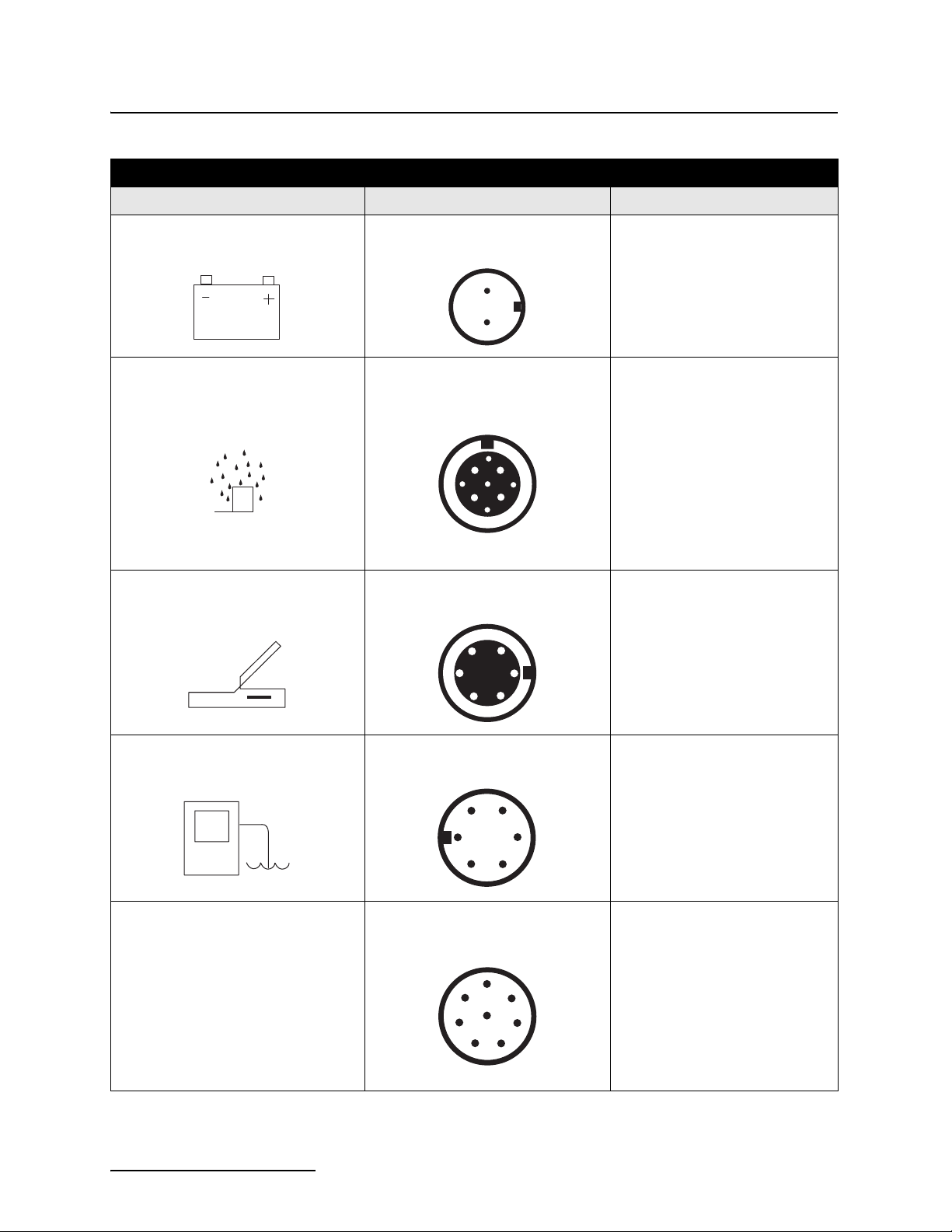
Connector Icon Pin Location Diagram Pin Function
Table 1-4 Connector Specifications
POWER SOURCE
2-PIN MALE, SEALED
A
B
RAIN GAUGE 9-PIN FEMALE, SEALED
E
A
D
F
I
H
B
C
G
INTERROGATOR 6-PIN FEMALE, SEALED
B
C
D
E
A
F
A Ground
B +12 volts DC
A +12 volts DC
B Ground
C Programmable I/O1 pin
D Rain gauge input
E Not Connected
F SDI-12 Data
G Not Connected
H Programmable I/O2 pin
I Programmable I/O3 pin
A Switched +12 volts DC
B Ground
C Connection Sense
D Transmit
E Receive
F NC
1-14
FLOW METER 6-PIN MALE, SEALED
C
B
MODULE
(
IN MODULE BAY)
A
IN MALE, SEALED
8-P
2
3
4
D
F
E
8
7
1
6
5
A +12 volts DC
B Ground
C Flow Pulses In
D Bottle Number Out
Dual Sampler Out
E Event Mark Out
F Inhibit In
1 NC
2 +12 volts DC
3 Ground
4 Module Sense
5 Receive
6 Transmit
7 Clock
8 Control
Page 31

6712FR Refrigerated Sampler
Section 2 Installation/Preparation
2.1 Preparing the Sampler The 6712FR is shipped to you with the controller mounted on the
refrigerator and a distributor shaft extension installed. Use
Figure 2-1 for reference when removing the controller. You must
remove the controller when:
• The internal desiccant needs recharging, the internal
battery needs to be replaced or when the controller
needs repair.
• You install a different bottle kit.
Each bottle kit has its own extension so that the distributor arm
is positioned at the right distance above the bottles. You must
remove the controller to replace the extension.
2.1.1 Installing the Distributor Shaft Extension
2.1.2 Mounting the Controller
1. Install the extension before mounting the controller on the
refrigerator.
2. Select the extension of the correct length for the bottle kit,
and screw it on the distributor shaft. Secure it with the set
screw. See Figure 2-1.
BE SURE THE SET SCREW IS TIGHTENED INTO THE
DISTRIBUTOR SHAFT’S KEY. YOU MAY HAVE TO
LOOSEN THE EXTENSION SLIGHTLY AND ADJUST ITS
POSITION.
1. Install the four mounting rods into the bosses on the bottom of the case.
2. Fit the mounting rods through the four holes drilled in the
top of the refrigerator.
3. Slip a washer on each rod and secure the controller by
tightening the wing nuts.
4. Install the distributor arm and discharge tube.
5. Thread the stop arm into the hole in the side of the extension. Be sure the stop arm is directly above the distributor
arm.
6. Connect the power cable to the controller.
2-1
Page 32

6712FR Refrigerated Sampler
Section 2 Installation/Preparation
Multiple-Bottle Sampling
1/4-20 Set Screw
Flat Washer
Distributor arm
Nut
Mounting Rod
Distributor Shaft
Extension
Wing Nut
Stop Arm
Distributor arm
Assembly
Composite Sampling
Mounting Rod
Flat Washer
Wing Nut
End of discharge tube
below neck of bottle.
Figure 2-1 Mounting the Controller
2.1.3 Installing the Distributor Arm and Discharge Tube
Distributor Arm
The distributor arm is adjustable so that you can position the
discharge tube over the bottles of each kit. Each bottle kit also
uses a discharge tube of a specific length. Table 2-1 lists the
correct discharge tube lengths for each bottle kit. If you are using
bulk tubing to cut your own tubes, cut the ends of the tube
square, not at an angle, and cut the length accurately.
The two-piece distributor arm has four positions, marked on the
underside with the letters A, B, C, and D. Adjust the arm to the
correct position for the bottle kit being used. Table 2-1 shows the
correct position for each kit. Thread the discharge tube through
the spring and arm so that the tube protrudes from the arm
1
/16
to 1/8 inch. If too much tube protrudes from the arm it can catch
on bottles and jam the distributor arm.
Attach the arm to the distributor shaft extension. Secure the arm
to the extension with the black plastic nut. Slide the free end of
the discharge tube onto the bulkhead fitting. After installing the
distributor arm and discharge tube, run the distributor to each
bottle position to ensure proper installation.
2-2
Page 33

6712FR Refrigerated Sampler
Section 2 Installation/Preparation
Table 2-1 Distributor Arm Positions and Discharge Tube Lengths for Bottle Kits
24-Bottle Kits
1000-milliliter polypropylene bottles
350-milliliter glass bottles
Distributor Arm Position: D
Discharge Tube: 60-9003-279
Discharge Tube Length: 20 inches (50.8 cm)
Distributor Shaft: 60-9003-273
11
Distributor Shaft Extension: 8
12-Bottle Kits
2.5 liter polyethylene bottles
Distributor Arm Position: D
Discharge Tube: 60-9003-279
Discharge Tube Length: 20 inches (50.8 cm)
Distributor Shaft: 60-9003-273
Distributor Shaft Extension: 8
8-Bottle Kits
1.8 liter glass bottles
2.0 liter polyethylene bottles
Distributor Arm Position: B
Discharge Tube: 60-9003-279
Discharge Tube Length: 20 inches (50.8 cm)
Distributor Shaft: 60-9003-274
Distributor Shaft Extension: 10
/16 inches (22.0 cm)
11
/16 inches (22.0 cm)
1
/2 inches (26.7 cm)
2-Bottle Kits
1
9.4 liter (2
/2 gallon) glass bottles
7.5 liter (2 gallon) polyethylene bottles
Distributor Arm Position: A
Discharge Tube: 60-9003-283
Discharge Tube Length: 16 inches (40.6 cm)
Distributor Shaft: 60-9003-275
Distributor Shaft Extension: 6 inches (15.2 cm)
Composite BottlesDischarge TubeDischarge Tube Length
1
9.4 liter (2
9.4 liter (2
15.0 liter (4 gallon) polyethylene bottle60-9003-26416
18.5 liter (5 gallon) glass bottle60-9003-26615
20.0 liter (5
/2 gallon) glass bottle60-9003-262171/4 in (43.8 cm)
1
/2 gallon) polyethylene bottle60-9003-262171/4 in (43.8 cm)
1
/2 in (41.9 cm)
3
/4 in (40 cm)
1
/2 gallon) polyethylene bottle60-9003-266153/4 in (40 cm)
2-3
Page 34

6712FR Refrigerated Sampler
Section 2 Installation/Preparation
2.2 Installing Bottle Kits Teledyne Isco ships the refrigerator from the factory with the
sample bottles in place. When using the sampler for the first
time, you will only need to remove the bottle lids. When
installing cleaned bottles or a new kit, keep these guidelines in
mind:
• Do not mix glass and plastic bottles together.
• Install all bottles to insure that they remain in place.
• Align the racks correctly. If the racks are misaligned, the
sampler may miss the bottle mouth, or the sampler will
deposit samples in the “wrong” bottle.
Each time you change from one size bottle to another, you must
adjust the length of the distributor arm, install a discharge tube
of the correct length, and possibly install a different distributor
shaft extension.
Each time you install a bottle kit, check the program settings for
the number of bottles and bottle volumes. Also rotate the distributor arm to each bottle position to ensure the arm is correctly
positioned over each bottle. Use the controller to move the arm.
2.2.1 Installing Racks Install the bottle rack with bottles by sliding it into the cooling compartment until the rack drops over the two semicircular ramps which hold it in place (Figure 2-2).
The five posts and two ramps which position the rack under the
distributor arm are adjusted at the factory. When you change
bottle kits, you may need to readjust the stops and ramps and
install a different distributor arm extension. Figures 2-3 and 2-4
show you how to install the bottle kits.
Check the kit’s alignment by rotating the distributor arm. Do
not rotate the distributor manually. Moving the arm manually damages the distributor drive. If you see any mis-
alignment, adjust the posts and ramps until the discharge tube
at the end of the arm stops over each bottle.
2-4
Page 35

6712FR Refrigerated Sampler
Section 2 Installation/Preparation
24-Bottle Kit
1000-milliliter polypropylene bottles.
Figure 2-2 Installing the Bottle Racks
Install the distributor shaft extension.
Use the 8
and 24-bottle kits. Use the 101/2-inch extension for the 8-bottle kit. The instructions on page 2-1 show you how to remove
the controller and replace the extensions
for each bottle kit.
Next, adjust the distributor arm to position
D for the 12-bottle and 24-bottle kits, or to
position B for the 8-bottle kit. Install the
arm and stop. See Installing the Distributor Arm and Discharge Tube on page 2-2.
Slide the rack, with bottles installed onto
the mounting plate. Adjust the stops and
ramps on the plate so that the rack is centered and held firmly on the plate.
Finally, position the arm over each bottle.
If the arm does not stop over each bottle,
readjust the rack.
11
/16-inch extension for the 12-
NEVER MANUALLY ROTATE
THE DISTRIBUTOR ARM.
Figure 2-3 Installing the 24-bottle, 12-bottle, and 8-bottle Kits
2-Bottle Kit
(Requires a locating base.)
Stop
(1 of 5)
Ramps
2-5
Page 36

6712FR Refrigerated Sampler
Section 2 Installation/Preparation
Install the distributor-shaft extension.
Use the 5
kit. Th e ins truct ions on pag e 2-1 show y ou
how to remove the controller and replace
the extensions for each bottle kit.
Next, replace the controller, and adjust the
distributor arm to position A. Install the
arm and stop. See Installing the Distributor Arm and Discharge Tube on page 2-2.
Install over the mounting plate at the bottom of the refrigerator, the locating base
which holds the 2
lon polyethylene bottles.
Begin by loosening the ramps. Move them
toward the front of the compartment so
that they will fit under the ridge of the locating base. (You can also remove them
completely.)
Remove the two front stops, and align the
holes on the sides of the locating base
with the holes for the stops in the mounting plate. Secure the base by replacing
the stops.
Install the bottles, and position the arm
over each bottle.
1
/4-inch extension for the 2-bottle
1
/2-gallon glass or 2 gal-
NEVER MANUALLY ROTATE
THE DISTRIBUTOR ARM.
Figure 2-4 Installing the 2-bottle Kit
Secure the base
with these stops.
Ramps located under locating base.
Pull them to the front or remove them.
2.2.2 Removing Racks Before removing the rack, place the lids on the bottles so the samples do not spill. Remove the bottle rack by lifting the front edge of the rack slightly to disengage it from the two ramps. Then, pull it straight out of the refrigerator. Be careful not to catch the distributor arm against the bottles.
2.2.3 Installing Composite
Bottles
Remove the distributor arm and discharge tube. Remove the distributor arm stop. If using the two bottle locating base, remove it.
Slide the composite bottle discharge tube on the bulkhead fitting.
Composite bottle kits have two lids, one with a hole drilled in the
center. Screw the lid with the hole in it on the bottle, and place
the bottle in the center of the mounting plate.
Thread the discharge tube through the hole in the lid. Always
use the lid to retain the discharge tube. It prevents the sampler
from spraying liquid inside the sample compartment instead of
the bottle.
2.3 Suction Line The suction line is the tubing from the sampling point to the
pump intake. The 6712FR uses a
3
/8-inch ID suction line of
lengths 3 to 99 feet. Teledyne Isco offers vinyl or PTFE suction
lines. The PTFE tubing has a polyethylene jacket to protect it
from kinks and abrasions.
2-6
Page 37

6712FR Refrigerated Sampler
Section 2 Installation/Preparation
The vinyl line contains a very low parts-per-million level of
phenols. If phenol content affects your sample analysis, use the
PTFE suction line.
When installing the sampler, be sure the vertical distance
between the liquid level and the pump is as small as possible.
2.3.1 Guidelines for
Measuring and Cutting
the Suction Line
2.3.2 Attaching Suction Line
to Pump Tube
• Cut the line to the desired length but use the shortest
length feasible for the installation.
• Cut the line in 1 foot increments. For instance, 4 feet,
1
/2. If using metric units of measure, cut the line in
not 3
increments of 0.1 meter. Do not include the length of the
strainer in the measurement.
3
Attach the vinyl suction line to the pump tube with the
/8-inch
tubing coupler. First, screw the threaded end into the suction line
until the flat surface is flush against the suction line
(Figure 2-5). Then, push the other end of the coupler into the end
of the pump tube until the other flat surface is flush against the
tubing.
1.
2.
Figure 2-5 Attaching the suction line to the pump tubing
Once the coupler is attached to the pump tube, removal is difficult, and may require cutting the tube.
2-7
Page 38

6712FR Refrigerated Sampler
7
diameter
Section 2 Installation/Preparation
2.4 Strainers Teledyne Isco offers three styles of strainer that help prevent
solids from clogging the suction line:
3
•
/8-inch standard weighted polypropylene strainer for
routine and priority pollutant sampling
3
•
/8-inch stainless steel low flow strainer
• Weighted CPVC-coated strainer for acidic liquid sources
To select the right strainer for your application, see Table 2-2.
To install the optional low flow strainer in PTFE suction line,
heat the end of the suction line to make it more pliable, then
carefully screw the strainer’s threaded connector into the suction
line.
2.4.1 Alternative to Strainers When sampling from high velocity streams with heavy suspended solids, some field investigations suggest that more representative samples are obtained without the strainer. Consider attaching a short piece of thin walled aluminum tubing to the end of the suction line; anchor the tubing so that the inlet opens upstream. The aluminum tubing’s thin wall will not disturb the flow stream, and most sample analyses disregard aluminum ions. Under most conditions, the pre-sample purge removes any debris over the tubing entrance.
Table 2-2 Selecting the Right Strainer
Strainer Dimensions Application Maximum Depth
3/8 Stainless
Steel Ends,
Polypropylene
Center
3/8
Stainless Steel
Low Flow
3/8
CPVC
1
.400
Diameter
1
.400
diameter
1
.400
diameter
10.5
11.5
.562
1- 5/16
Diameter
1-1/4
Diameter
Routine
applications.
Low flow
applications
Highly
acidic
liquids.
Vinyl Line:
22 feet (6.7m).
PTFE Line:
15 feet (4.5m).
Vinyl Line:
22 feet (6.7m).
PTFE Line:
15 feet
Vinyl Line:
4 feet (1.2m).
(4.5m).
Note
• The suction lines will float when filled with air during the purge cycles and when depths exceed the
listed ratings. Secure the suction lines when sampling at depths exceeding the maximum ratings.
• All strainer dimensions are in inches.
• PTFE suction line is compatible only with the
3
/8 stainless steel strainer.
2-8
Page 39

6712FR Refrigerated Sampler
Section 2 Installation/Preparation
2.5 How Does the Sampler Work?
When the sampler takes a sample, it draws liquid through the
strainer and suction line to the pump tube. The liquid flows
through the pump tube and past the liquid detector, which senses
the liquid. From the detector, the liquid follows the pump tube
through the pump to the bulkhead fitting and then through the
discharge tube to the sample bottle.
A typical sampling cycle consists of:
1. The sampler moves the distributor arm over the bottle that
is to receive the sample.
2. The pump reverses for the pre-sample purge.
3. The pump direction changes, filling the suction line.
4. When the detector senses liquid, the sampler begins measuring the sample.
5. After depositing the sample, the pump again reverses for
the post-sample purge.
Sampling cycles vary somewhat according to program settings
for distribution. The sampler can move the distributor arm
clockwise and counterclockwise, making a number of distribution
methods possible. (In this manual, the words “sample event”
refer to a full sampling cycle for any distribution.)
a. Controller.
b. Peristaltic pump.
c. Liquid Detector.
d. Strainer
e. Suction line
f. Stainless Steel Coupling
g. A pump tube routed from the liq-
uid detector’s intake port
through the pump, out the detector’s discharge port, and over the
side of the controller to a bulkhead fitting.
h. Bulkhead fitting.
i. Discharge tube running from the
bulkhead through the spring and
distributor arm.
j. Distributor arm and spring.
Figure 2-6 Identifying the Sampler Components
Other variations include extended-program settings for
suction-line rinses and sampling retries. A sampler running a
program with line rinses completes the pre-sample purge and
e
f
g
c
b
h
a
i
j
d
2-9
Page 40

6712FR Refrigerated Sampler
Section 2 Installation/Preparation
then rinses the line. The suction line is purged after each rinse.
When programmed for sampling retries, the sampler will
attempt to pump a sample again if it fails on previous attempts.
2.5.1 Measuring Sample Volume
“Sample volume” refers to the amount of liquid delivered into a
bottle. The volume is determined by the programmed value. The
volume is dependent on the volume per revolution of the pump,
which is dependent on the suction head. The 6712FR delivers the
sample by counting the pump revolutions and automatically
compensating for the suction head.
2.6 Installing the Sampler The following segment briefly describes initial sampler instal-
lation.
CAUTION
Tests indicate that the pump produces sound levels in excess
of 85db at one meter. Prolonged exposure to this sound could
result in hearing loss and requires the use of protective ear
plugs.
CAUTION
When using the 6712FR sampler with a 750 or 710 module,
transmitters such as cell phones or walkie talkies must not be
operated within 3 meters of the sampler. If water level readings
are fluctuating due to TV/radio station transmitter towers in the
area, the sampler must be relocated.
2.6.1 Tips for Routing Suction Line
WARNING
The 6712FR samplers have not been approved for use in
hazardous locations as defined by the National Electrical
Code.
WARNING
If you must enter a manhole or other dangerous location to
install the sampler, observe standard safety precautions.
Refer to Appendix C for a discussion of safety
considerations.
Route the line so that it runs continuously downhill from the
sampler to the liquid source. This helps drain the line during
pre-sample and post-sample purges. When the sampler is used in
below freezing temperatures, there is a risk of the suction line
being frozen. A suitably warm sampling source can usually
prevent this, provided there are no loops in the suction line.
Some situations may require more protective measures, such as
insulation of the suction line, or heat tape. Thoroughly draining
the suction line minimizes the possibility of frozen liquid
clogging the line.
2-10
Page 41

6712FR Refrigerated Sampler
Section 2 Installation/Preparation
2.6.2 Intake Placement For representative samples, place the intake in the main current
of the flow stream, not in an eddy or at the edge of flow. Placing
an intake at the bottom may produce samples with excess heavy
solids and no floating materials, while placement at the top may
produce the opposite conditions.
2.6.3 Positioning a Sampler Place the refrigerator on a relatively flat, horizontal surface.
Placing the refrigerator on a steep incline may cause the sample
to miss the bottle mouth.
When installing the sampler, be sure the vertical distance
between the level of the liquid and the pump is as small as possible.
CAUTION
The refrigerator’s lower compartment is not watertight. Do not
install in a location where the refrigerator’s lower compartment
could become submerged.
2.7 Connecting External Instruments
2.7.1 Flow Meter To connect the sampler to an Isco open-channel flow meter, 4100
Flow Meter
Connector
Icon
The 6712FR sampler can be used in conjunction with several
types of external instruments.
series flow logger, 2100 series flow module, or 1640 Liquid Level
Actuator, attach the sampler-to-flow meter cable to the Flow
Meter Connector. To connect the sampler to a closed-pipe flow
meter, attach an Isco 4-20 mA Input Interface device to the
sampler’s Flow Meter connector. Plug the line cord into an AC
power outlet. Be sure it is connected to 120 volts AC (optional
230 volts AC). When using the sampler with an external
instrument, remember these guidelines:
• Both the sampler and the flow instrument must be on
and running a program.
• If using a flow meter, logger, or module for flow pacing,
the sampler and the flow instrument must both run
programs with flow pacing settings.
• If using a flow meter or flow logger for trigger pacing,
the sampler must run a program with flow pacing
settings, and the flow instrument must run a program
with trigger pacing settings.
• When the sampler runs an event-paced program, it
disregards pacing pulses from a flow meter or flow
logger. However, the sampler continues to monitor for
enable signals.
2.7.2 Rain Gauge Connector Connect the rain gauge, SDI-12 Sonde, or Refrigerator Temperature Sensor connect cables to the nine-pin Rain Gauge Connector. When connecting a rain gauge and an SDI-12 Sonde, or rain gauge and a Refrigerator Temperature Sensor, use the appropriate Y-connect cable. See the Accessories appendix at the end of this manual.
2-11
Page 42

6712FR Refrigerated Sampler
Section 2 Installation/Preparation
Rain Gauge
Connector Icon
WARNING
Most Isco flow meters are not certified for use in hazardous
locations as defined by the National Electrical Code.
Contact your Teledyne Isco representative for your
equipment’s status. Never operate equipment in hazardous
locations that has not been certified as safe for such use.
Refer to Appendix C in the back of this manual for more
safety information.
Note
Select Extended Programming to use the SDI-12 sonde. (See
Switching Between Standard and Extended Modes on page
4-1.)
Note
Update the Hardware Setup whenever you add or remove an
SDI-12 sonde. (See Section 6.) In extended programming, rain
gauge and SDI-12 sonde readings are only available if they are
selected in the Hardware Setup.
2-12
Page 43

Table 2-3 Connecting Isco Instruments to the Sampler
Connector Icon Connect These Instruments:
Power Source
Rain Gauge
Interrogator
Flow Meter
12 volt power source
674 Rain Gauge
Programmable I/O Pins (pins C, H, and I)
SDI-12 Sonde
Refrigerator Temperature Sensor
581 RTD (Rapid Transfer Device)
IBM PC or compatible computer running FLOWLINK or SAMPLINK
External Modem
External Data Logger/Controller
1640 Liquid Level Actuator
2100 Series Flow Modules
3000 Series Flow Transmitters
4100 Series Flow Loggers
4200 Series Flow Meters
Master/Slave Sampler
Pulse Duration Input Interface
4-20 mA Input Interface
Closed-Pipe Flow Meter (with 4-20 mA Input Interface)
6712FR Refrigerated Sampler
Section 2 Installation/Preparation
2-13
Page 44

6712FR Refrigerated Sampler
Section 2 Installation/Preparation
2.8 Locking the Sampler The refrigerator is equipped with a lockable latch for the top
cover and a lockable catch for the door handle. To lock the refrigerator, use two padlocks, one for the top cover and one for the
door.
2.9 Servicing the Sampler Servicing the sampler includes:
• Collecting the filled sample bottles and replacing them
with clean bottles;
• Collecting the data recorded by the sampler during the
program.
Samplers are usually serviced after they complete a sampling
program. When working up a service schedule, you will need to
estimate the program completion time. You should also be
familiar with the program’s settings for the start time or if the
sampler is programmed for continuous sampling.
Continuous sampling is controlled by the distribution setting
entered at the “RUN CONTINUOUSLY?” screen. A “YES”
response directs the sampler to reset the distribution sequence
and continue the countdown to the next sample event. Appropriate service intervals will prevent overfilled bottles.
2-14
Page 45

6712FR Refrigerated Sampler
Section 3 Programming Introduction
Before programming the 6712FR, you should become familiar
with its keys and how to use the screens.
The 6712FR Sampler has two sets of programming modes. The
first mode, Standard Programming, lets you set up typical
sampling programs easily and efficiently. The second mode,
Extended Programming, lets you create sophisticated programs for complex sampling applications.
All of the sampling features available in standard programming
mode are available in extended programming mode. However,
extended programming provides many additional features.
Standard and extended programming features are explained in
separate sections. This section focuses on some basic features
that are common to both programming modes, such as using the
menus and setting the clock.
3.1 Initial Operation
CAUTION
This sampler has a high performance pump. As with all such
pumps, it relies upon liquid to cool working components. If the
sampler is programmed to pump in the absence of liquid in
excess of 5 minutes, excessive heat buildup may damage the
paddles, rollers, and housing. Ensure that the liquid inlet is
completely immersed.
Turn the sampler on by pressing the Standby key. It is labeled
with this icon: . The start-up screen appears first.
6712 SAMPLER
STANDARD PROGRAMMING
For HELP at any
screen press ? key.
It remains on the display for about eight seconds or until you
press a key. It tells you the type of programming screens the
sampler is currently using — standard or extended — and gives
you a tip about the on-line help. The main menu screen, shown
below, appears next.
RUN
PROGRAM
VIEW REPORT
OTHER FUNCTIONS
3-1
Page 46

6712FR Refrigerated Sampler
Section 3 Programming Introduction
Table 3-1 About the Keypad
Key Name Function
(If a module is attached, a different screen may appear first. See
the module manual for more information.)
Standby Turns sampler on or off.
Stop
Enter Accepts a menu choice or number entry and goes to next screen.
Help In programming screens, displays a brief help message.
Down-Right
Arrow
Up-Left Arrow Selects the menu option left or above the current choice.
Numbers Types a number.
Decimal Point Types a decimal point.
Pump Reverse Press when at the main menu to run the pump in reverse.
Pump
Forward
Stops the pump or distributor. Pauses a running sampling program.
In programming screens, returns to a previous screen.
Selects the menu option right or below the current choice.
Press when at the main menu to run the pump forward.
3-2
Page 47

6712FR Refrigerated Sampler
Section 3 Programming Introduction
The sampler is programmed at the factory so that the standard
programming screens appear when you first turn the sampler on.
You can switch between programming modes by typing in a
numerical command at the main menu:
• At the main menu type 6712.2 to show the extended
programming screens.
• At the main menu type 6712.1 to show the standard
programming screens.
The sampler will continue to use the program mode you selected,
even if the sampler is turned off and on again, until you manually switch to the other programming mode.
With the display backlight activated, the screen will glow for
several seconds following your last keystroke.
If you press a key and the screen text does not change, it is
probably because the keystroke turned the backlight on, instead
of performing its function. Press the same key again.
3.1.1 Selecting a Language You have the option of having screens display in English or another language. The default is English. At the main menu, type 6712.8:
3.2 Using Menus and Entering Numbers
The Main Menu
RUN
PROGRAM
VIEW REPORT
OTHER FUNCTIONS
3.2.1 Selecting Menu Options
ENGLISH
SPANISH
Use the arrow keys to move between the choices (languages other than
those shown above could appear on your unit). When the language
choice you want is blinking, press
↵(Enter). The ↵ (Enter) key
always accepts the blinking option.
A menu is a list of options. The main menu has four options:
•RUN
• PROGRAM
•VIEW REPORT
• OTHER FUNCTIONS
The options identify the operations that can be performed from
the menu. For example, to run the sampling program, select
RUN; to modify the program, select PROGRAM.
In menu screens, one menu option always blinks.
•Press ↵ when the blinking option is the one you want; it
will accept your choice and go to the next screen.
• Select a different option by pressing an arrow key until
the option you want blinks. Then press ↵.
3.2.2 Entering Numbers Number-entry screens prompt you to enter a value. An example
is shown to the left.
3-3
Page 48

6712FR Refrigerated Sampler
Section 3 Programming Introduction
To enter a number:
Press the number keys to type the number. Then, press ↵. As
SUCTION LINE LENGTH
IS __ ft
(3-99)
soon as you press ↵, the sampler saves your number and moves
to the next screen. In some screens, you can use the . (Decimal
Point) key in a number.
•Type the length of the
suction line. Acceptable
values are shown between
the parentheses. Press
accept the number.
↵ to
Some screens display the range of acceptable numbers between
parentheses. If an entry is too low or high, the controller beeps
and erases the entry. Type a new number and continue.
3.3 Quick View Screens Quick View screens are a special type of menu screen. They show
the current program settings and let you move quickly through
the program. You must change the programming style to QUICK
VIEW/CHANGE to see the quick view screens, as shown below:
3.3.1 Paging Through Quick View Screens
RUN
1
2
3
PROGRAM
VIEW REPORT
OTHER FUNCTIONS
MAINTENANCE
MANUAL FUNCTIONS
PROGRAMMING STYLE
PROGRAMMING STYLE
NORMAL
QUICK VIEW/CHANGE
Select OTHER FUNCTIONS.
Select PROGRAMMING STYLE.
Select QUICK VIEW/CHANGE.
The arrows in the corners of each quick view screen are menu
options that let you move from one quick view screen to another.
Select the up arrow ( ↑ ) to go to the previous screen.
Select the down arrow ( ↓ ) to go to the next screen.
Press Stop to return to the main menu.
Because the forward arrow is always blinking when the screen
appears, you can simply press ↵ to go to the next quick view
screen, making it easy to page through the screens.
3.3.2 Changing Settings in a Quick View Screen
3-4
Although the quick view screens offer you a quick way to see the
program settings, they also provide you with a way to change settings. Using quick view screens to change settings is sometimes a
faster way to change a program because you can go quickly to the
setting or settings that needs updating.
To change the program settings in a quick view screen:
Press an arrow until the setting blinks. Press ↵. The 6712 then
displays the screen used to change the setting.
Page 49

RUN
PROGRAM
VIEW REPORT
OTHER FUNCTIONS
•To see the Quick View
screens, select PROGRAM.
↑
SITE DESCRIPTION:
“SITE 29 “
•Use the keypad’s arrow key
to select ↓ for the next quick
view screen. When ↓ is
blinking, press
•Use the keypad’s arrow key
to select ↑ for the previous
quick view screen. When ↑
is blinking, press
•Use the keypad’s arrow key
to select the program
setting. When the setting is
blinking, press
the screen used to change
the setting.
•Press Stop for the main
menu.
•All quick view screens work
the same way.
↵.
↵.
↵ to display
6712FR Refrigerated Sampler
Section 3 Programming Introduction
The following Quick View screens show you how to change the
sample volume. Begin by paging through the quick view screens
until you see the screen containing the sample volume setting:
↑
200 ml SAMPLES
↓
•Press the arrow key until
200 ml
SAMPLES blinks. Then
press
↵.
↓
SAMPLE VOLUME:
250 ml (10-1000)
•Type the new sample volume
and press
↵.
↑
250 ml SAMPLES
↓
When you change a setting, the sampler stores the new settings
and returns to the updated quick view screen. You can repeat
this process until all settings shown in the quick view screens
have been changed. When you are done, select the screen’s
forward arrow to move to the next quick view screen, or press
Stop to return to the main menu.
3.4 Clock and Calendar You may have to set the internal clock or calendar. The samplers
are shipped with their clocks set to U.S. Central Standard time.
If your sampler operates in a different time zone, you will have to
reset the clock. The example below shows you how to find the
time and date screen.
3-5
Page 50

6712FR Refrigerated Sampler
Section 3 Programming Introduction
Entering Times and Dates
ENTER TIME AND DATE:
HH:MM DD-MON-YY
__:__ __-__-__
•Move from one field to
another by pressing the
arrow keys.
•Change a setting in a field
by typing a number. Press
to accept the new setting.
3.4.1 Setting the Clock and Calendar
↵
When setting the clock and calendar, use a 24-hour clock for
times and the day-month-year format for dates. The illustration
at the left shows blanks for each position that accepts an entry.
The positions are called fields. When this screen appears on your
sampler, the fields will contain the sampler’s current settings for
the time and date.
• To move from one field to another without changing the
setting, press the arrow keys. Use this technique when
you want to change only one or two settings.
• Change the setting by typing a new number. Press ↵ to
accept the new setting.
For example, to enter 2:00 p.m. (2:00 p.m is 14:00 on a 24-hour
clock), type 14. Press ↵. Next, type 0 (zero) for the minutes, and
press ↵. To enter a date, such as January 22, 2001, type: 22 ↵
01 ↵ 01 ↵ .
RUN
1
2
PROGRAM
VIEW REPORT
OTHER FUNCTIONS
MAINTENANCE
MANUAL FUNCTIONS
PROGRAMMING STYLE
Select OTHER FUNCTIONS.
Select MAINTENANCE.
3.4.2 Menu Screens: Clock Start Times
SET CLOCK
3
4
5
PUMP TUBE ALARM
INTERNAL BATTERY
DIAGNOSTICS
ENTER TIME AND DATE:
HH:MM DD-MON-YY
14:00 22-JAN-01
SET CLOCK
PUMP TUBE ALARM
INTERNAL BATTERY
DIAGNOSTICS
Select SET CLOCK.
Enter the time and date.
Press Stop to return to the main
menu.
There are four start time settings you can use in a sampling
program. This section discusses only one of these settings, the
clock start time. A clock start time lets you set up a sampling
program that starts at the same time on one or more days of the
week. For example, you may want to begin sampling at 6:00 a.m.
on Monday through Friday (refer to the screen below).
To select a day or days from the menu:
1. Press an arrow key until the cursor is on the correct day.
Then, press ↵.
2. Repeat these steps until each day you want is blinking.
3. Press an arrow until DONE blinks. Press ↵.
3-6
Page 51

6712FR Refrigerated Sampler
Section 3 Programming Introduction
To remove days from the list:
1. Press an arrow key until the cursor is on the day you want
to remove. Press ↵ to deselect it.
2. When finished, select DONE and press ↵
NO DELAY TO START
DELAYED START
CLOCK TIME
WAIT FOR PHONE CALL
•Select CLOCK TIME.
FIRST SAMPLE AT:
06:00
•Type the time of day and
↵.
press
SELECT DAYS:
SU MO TU WE TH FR SA
DONE
•Press an arrow key until the
cursor is on the correct day.
Then, press
day, move the cursor to it
and press ↵ to deselect it.
•Repeat these steps
until each day you want
is blinking.
•Press an arrow until DONE
blinks. Press
↵. To remove a
↵.
Using the Clock
Start Time Menu
3.5 Menu Screens: Site Descriptions and Program Names
The sampler has two text-entry menus, one for site description
and another for an extended-program name. They work in the
same way. A site description is commonly a number, address, or
other short note that helps identify the monitoring site.
Extended programming has a similar screen that lets you enter
program names for stored programs.
The example on the next page shows how to change the site
description from FACTORY01 to SITE 29. Line 1 contains text
between two quotation marks. Lines 2 and 3 contain the menu
options — numbers, letters, and punctuation marks — used to
spell out the description. In line 3, the space between the
ampersand (&) and the double quotes (") is a space character.
Line 4 contains two additional options:
• BACK-UP, an option that moves the cursor on the text
line to the left one character.
• DONE, an option that tells the sampler to save the text.
3-7
Page 52

6712FR Refrigerated Sampler
Section 3 Programming Introduction
Changing the Site Name
SITE: “FACTORY01”
ABCDEFGHIJKLMNOPQRST
UVWXYZ-& “0123456789
BACK-UP DONE
SITE: “S
ABCDEFGHIJKLMNOPQRST
UVWXYZ-& “0123456789
•Press the Down-Right arrow
until the S on line 2 blinks.
Then, press ↵.
SITE: “SICTORY051”
ABCDEFGHI
UVWXYZ-& “0123456789
•Press the Up-Left arrow
until the I blinks. Press
•Continue pressing arrow
keys to select T, E, and
space. Press
selecting each character.
ABCDEFGHIJKLMNOPQRST
UVWXYZ-&_"0123456789
•Press 29 on the keypad, then
Up-Left until space blinks.
Press ↵.
ABCDEFGHIJKLMNOPQRST
UVWXYZ-&_"0123456789
ACTORY01”
BACK-UP DONE
JKLMNOPQRST
BACK-UP DONE
↵.
↵ after
SITE: “SITE 29_ ”
BACK-UP DONE
SITE: “SITE 29 ”
BACK-UP DONE
The cursor is the blinking rectangle that identifies the current
field. When the screen first appears, the cursor blinks on the first
character of the text in line 1. The matching character in line 2 or
3 also blinks.
When you press ↵, the cursor on line 1 moves to the right one
position, and, at the same time, the sampler blinks on the
matching character on lines 2 or 3.
To change any character in the text line:
1. Press the left or right arrow until the replacement character on lines 2 or 3 blinks.
2. Press ↵. The replacement character will appear on the first
line, and the cursor will move to the next character.
Repeat steps 1 and 2 until the text in the top line is complete.
3. Finish the entry by selecting DONE. Then, press ↵.
Some additional tips for using the text-entry menus:
• Hold an arrow key down for faster movement.
• If your description uses all ten spaces in the text line,
the sampler automatically moves to the next screen as
soon as you add the tenth character.
• You can enter numbers by pressing the number keys.
• Erase characters by replacing them with a space
character.
• Select the BACK-UP option to move the cursor to the
left.
• To leave the menu before completing the entry, press
Stop. The sampler will display this menu:
•Press the Down-Right arrow
until DONE blinks. Press
↵.
SAVE CHANGES?
YES NO
Select YES to save any changes made. Select NO to
leave the original description (or program name)
unchanged.
3.6 Messages The sampler has four sets of messages that supplement the pro-
gramming screens. Information messages tell you about programming status. Help Notes are brief comments associated
with programming screens describing the setting or offering
assistance. Warning messages tell you something is different
from Isco’s standard. Operation messages report the sampler’s
status as it runs a program.
3-8
Page 53

6712FR Refrigerated Sampler
Section 3 Programming Introduction
3.6.1 Information Messages These are brief messages about the programming status, such as “‘ROM’ PASSED TEST” or the status message that displays when you first start up the sampler. Information messages are displayed for four seconds, unless they are terminated by pressing any key on the keypad.
3.6.2 Help Notes To see a Help note:
1. Press the ? (Help) key.
2. When the note requires several screens, the word “more”
appears in the lower-right corner. Press ↵ for the next note.
3. Move back and forth between screens by pressing the
arrow keys.
4. Press Stop at any time to return to the programming
screen.
Most help notes refer to a related section in this manual. Screens
that require extensive explanation have notes that contain only a
reference to the manual. Sections mentioned in the notes appear
in the index and the table of contents.
SUCTION LINE LENGTH
•Press ? (Help).
Enter the length of
suction line only,
excluding strainer
and pump tube. <more>
•Press ↵ or Down-Right to
see the next screen.
•Press Stop to return to the
programming screen.
See “Installing
Suction Line” in
your manual.
•Press
see the next screen.
•Press Up-Left to see the
previous screen.
•Press Stop to return to the
programming screen.
Press the red STOP
key to exit HELP.
IS 7 ft
(3-99)
<more>
↵ or Down-Right to
Using Help Notes
Although this example shows
the Help Notes that are associated with the suction line
length screen, you can use the
same technique to see help
notes for other screens.
•Press Up-Right to see the
previous notes.
•Press Stop to return to the
programming screen.
3-9
Page 54

6712FR Refrigerated Sampler
Section 3 Programming Introduction
3.6.3 Warning Messages Warning messages appear when the sampler determines something is out of the ordinary. For example, the following warning appears when you type a number that is larger than the standard bottle volume:
BOTTLE VOLUME IS
3500 ml (300-30000)
WARNING!
STANDARD BOTTLE
VOLUME EXCEEDED!
The 6712 does accept nonstandard volumes because you might
use a nonstandard container occasionally. For a list of recommended volumes for Isco bottles press the ? (Help) key at the
“Bottle Volume Is” screen, or refer to the Technical Specifications.
The 6712 uses the bottle and sample-volume settings to
determine the maximum number of samples that can be
deposited without overfilling the bottles. Entering a volume that
exceeds the standard volume may cause the sampler to overfill
the bottle.
3.6.4 Operation Messages An operation message reports the sampler’s status as it runs a program. An example is shown below.
PROGRAM WILL START
AT 06:00 TU 20-FEB
05:56:22 TU 20-FEB
3.7 Menu Trees Selecting a menu option will take you to a number-entry screen
or another menu screen. The screens are organized in a
branching structure that resembles a tree. Refer to Figure 3-1 for
a simple chart of the menu tree for standard programming. The
standard programming structure is different — much simpler —
than the extended programming structure. Charts that show you
most of the sampler’s screens appear in Appendix A, Flowcharts.
The entire structure changes a little when a module is attached
because the sampler adds a set of screens for a module as soon as
it detects the module’s presence. The manuals for each module
contain menu trees for its programming screens.
3-10
Page 55

6712FR Refrigerated Sampler
Section 3 Programming Introduction
RUN
PROGRAM
VIEW REPORT
OTHER FUNCTIONS
VIEW DATA
PRINT DATA
SYSTEM IDs
CONFIGURE REPORTS
MAINTENANCE
MANUAL FUNCTIONS
PROGRAMMING STYLE
See Running Programs on page 4-10
See the screen charts in Appendix A.
See Reports on page 4-18.
SET CLOCK
SET PUMP TUBE ALARM
INTERNAL BATTERY
DIAGNOSTICS
See Figure A-8, Manual Functions
Screens, on page A-8.
PROGRAMMING STYLE:
QUICK VIEW/CHANGE
Figure 3-1 Menu Tree for Standard Programming
NORMAL
3-11
Page 56

6712FR Refrigerated Sampler
Section 3 Programming Introduction
3-12
Page 57

6712FR Refrigerated Sampler
Section 4 Standard Programming
The 6712FR Sampler has two sets of programming screens. The
first set, called standard programming screens, lets you set up
typical sampling programs easily and efficiently. The second set,
extended programming screens, lets you create sophisticated
programs for complex sampling applications.
All of the sampling features available within the standard programming screens are available in extended programming.
However, extended programming provides several additional features which are discussed in the next section. Menu flowcharts
for both sets of programming screens are in Appendix A.
4.1 Switching Between Standard and Extended Modes
4.2 Language Selection, Units of Length
Factory default settings cause the sampler to begin in standard
programming mode the first time you turn it on. The start-up
screen tells you which programming mode the sampler is currently using. You can switch between programming modes by
entering a numerical command at the main menu:
• At the main menu, type 6712.1 to enter standard
programming mode.
• At the main menu, type 6712.2 to enter extended
programming mode.
RUN
PROGRAM
VIEW REPORT
OTHER FUNCTIONS
Main Menu
You have the option of displaying screens in English or Spanish
(or possibly another language). The default is English. At the
main menu, type 6712.8 to display:
ENGLISH
SPANISH
Use the arrow key to move between the two choices. When the
desired choice is blinking, press ↵.
If you select the English option, you will advance to a second
screen that asks you to select your units of length:
SELECT UNITS FOR
LENGTH:
ft m
4-1
Page 58

6712FR Refrigerated Sampler
Section 4 Standard Programming
Use the arrow key to move between the two choices, feet or
meters. When the desired choice is blinking, press ↵. The default
unit of length for the Spanish option is meters.
4.3 Programming Examples
The following table is an example of time-paced sampling.
Further details about some of the menu items are provided in
later sections.
Table 4-1 Standard Program: Sample Every 15 Minutes, One Sample Per Bottle
6712 SAMPLER
STANDARD PROGRAMMING
1
2
3
4
5
For HELP at any
screen press ? key.
RUN
PROGRAM
VIEW REPORT
OTHER FUNCTIONS
SITE DESCRIPTION:
“FACTORY051“
CHANGE?
YES NO
NUMBER OF BOTTLES:
12481224
BOTTLE VOLUME IS
1000 ml (300-30000)
Turn the sampler on by pressing the On/Off key. Press ↵.
This screen disappears on its own after 8 seconds.
The option PROGRAM will be blinking. Press ↵.
The option NO will be blinking. Press ↵.
For the purposes of this example, it isn’t necessary to change the description.
Select the number of bottles in your bottle kit by pressing either arrow key
until the correct number blinks. Press
Type the volume for the bottles in your kit. For this example, 1000 is correct,
so simply press
↵.
↵. For this example, select 24.
6
7
8
9
10
SUCTION LINE LENGTH
0 HOURS, 15 MINUTES
RUN CONTINUOUSLY?
IS 10 ft
(3-99)
TIME PACED
FLOW PACED
TIME BETWEEN
SAMPLE EVENTS
SEQUENTIAL
BOTTLES/SAMPLE
SAMPLES/BOTTLE
YES NO
Type the length of the suction line, then press ↵.
If you change the length, the sampler will display a message,
“PLEASE WAIT!. . . GENERATING PUMP TABLES.”
Because this example requires samples every 15 minutes, select TIME
PACED by pressing an arrow until the option TIME PACED blinks. Then,
press
↵.
Type 0 for hours and press ↵. Type 15 for minutes and press ↵.
Tip: Move back and forth between hours and minutes by pressing an arrow
key.
Because this program requires one sample in each bottle, select
SEQUENTIAL by pressing an arrow until the option SEQUENTIAL blinks.
Then, press
For this example, select NO by pressing an arrow until the option blinks.
Then, press
repeating the sample distribution. Continuous sampling assumes that filled
bottles are replaced with empty bottles at regular service intervals.
↵.
↵. Selecting YES allows the program to run indefinitely by
4-2
Page 59

6712FR Refrigerated Sampler
Section 4 Standard Programming
Table 4-1 Standard Program: Sample Every 15 Minutes, One Sample Per Bottle (Con-
11
12
13
14
15
SAMPLE VOLUME:
200 ml (10-1000)
NO DELAY TO START
DELAYED START
CLOCK TIME
WAIT FOR PHONE CALL
FIRST SAMPLE
AFTER A
5 MINUTE DELAY
(1-999)
PROGRAMMING COMPLETE
RUN THIS PROGRAM
NOW?
YES NO
RUN
PROGRAM
VIEW REPORT
OTHER FUNCTIONS
Type the volume of the sample you want deposited in each bottle. Then,
press
↵.
For this example, select DELAYED START by pressing an arrow until the
option blinks. Then, press
Type the delay period you want between the time you run the program and
the time the sampler takes the first sample. Then, press
Run the program immediately by selecting YES. Select NO if you want to
run the program later by selecting RUN from the main menu. Press
making your choice. In this example, NO is selected.
Run the program by selecting RUN and pressing ↵.
↵.
↵.
↵ after
The following table is an example of flow-paced sampling.
• Program type: Standard
• Site description: SITE 29
• Bottle kit: 24, 1000 milliliter bottles
• Suction line length: 7 feet
• Pacing: Flow pacing, every two pulses
• Distribution: 2 bottles per sample
• Sample Volume: 250 milliliters
• Start time: Clock Time, 6:00 a.m. on Monday,
Wednesday, Friday
• Module: No module installed
Table 4-2 Standard Program: Flow-Paced Sampling, Two Bottles Per Sample
6712 SAMPLER
STANDARD PROGRAMMING
1
2
3
For HELP at any
screen press ? key.
RUN
PROGRAM
VIEW REPORT
OTHER FUNCTIONS
SITE DESCRIPTION:
“FACTORY051“
CHANGE?
YES NO
Select PROGRAM.
Select NO.
4-3
Page 60

6712FR Refrigerated Sampler
Section 4 Standard Programming
Table 4-2 Standard Program: Flow-Paced Sampling, Two Bottles Per Sample (Contin-
4
5
6
7
8
9
NUMBER OF BOTTLES:
12481224
BOTTLE VOLUME IS
1000 ml (300-30000)
SUCTION LINE LENGTH
IS 10 ft
(3-99)
TIME PACED
FLOW PACED
FLOW BETWEEN
SAMPLE EVENTS:
2 PULSES (1-9999)
SEQUENTIAL
BOTTLES/SAMPLE
SAMPLES/BOTTLE
Select 24.
Enter 1000.
Enter 7.
Select FLOW PACED.
Enter the number of pulses between sample events.
Select BOTTLES/SAMPLE.
10
11
12
13
14
15
RUN CONTINUOUSLY?
YES NO
1 BOTTLES PER
SAMPLE EVENT (1-24)
NO DELAY TO START
DELAYED START
CLOCK TIME
WAIT FOR PHONE CALL
START FLOW COUNT AT:
SU MO TU WE TH FR SA
PROGRAMMING COMPLETE
RUN THIS PROGRAM
00:00
SELECT DAYS:
DONE
NOW?
YES NO
For this example, select NO by pressing an arrow until the option blinks.
Then, press
↵. Selecting YES allows the program to run indefinitely by
repeating the sample distribution. Continuous sampling assumes that filled
bottles are replaced with empty bottles at regular service intervals.
Enter 2.
Select CLOCK TIME.
Enter 6, then enter 0.
This is the time at which the sampler will start the pacing countdown.
Select MO, WE, and FR.
Use the arrow keys and
blinking, select DONE and press
↵ to select the days. When the correct days are
↵.
Select NO.
4-4
Page 61

4.4 Pacing
Standard Time Pacing and
Flow Pacing Screens for
Samplers without Flow
• When programming, you will
be asked to select time or flow
paced sampling. Depending
upon your choice, you will see
one of the following screens:
Flow Pacing Screen for
Samplers with Flow Modules
Modules
TIME PACED
FLOW PACED
TIME BETWEEN
SAMPLE EVENTS:
__ HOURS, __ MINUTES
FLOW BETWEEN
SAMPLE EVENTS:
____ PULSES (1-9999)
FLOW BETWEEN
SAMPLE EVENTS:
____ Mgal
(0.001 -99999)
6712FR Refrigerated Sampler
Section 4 Standard Programming
Sample pacing is the rate at which the sampler takes samples.
Depending on the type of pacing you select, the rate is controlled
by the sampler’s internal clock or by inputs received from connected instruments.
Standard programming provides time pacing and flow pacing
(refer to Step 7 in the previous two programming examples). In
time-paced sampling, the interval between samples is a constant
time interval. When you program the sampler for time pacing,
the sampler prompts you to enter the time between sample
events in hours and minutes. Time paced programs always take
a sample at the start time.
Flow paced sampling requires a flow meter, flow logger, or a
module. A flow meter or flow logger paces a sampler by sending
an electronic signal to the sampler after measuring a specified
volume of liquid. Because each pulse represents a volume
interval, flow pacing rates are proportional to the volume of
water flowing through the channel.
When you program the sampler for flow pacing and are using a
flow meter or flow logger, the sampler prompts you to enter the
interval between sample events in pulses. The sampler initiates
a sample event when the set number of pulses is received. Programs that are flow paced do not take a sample at the start time.
After setting the program start time, you will be prompted to
enter a maximum run time of zero to 999 hours. If you would like
the program to run indefinitely, enter 0 (zero) for maximum run
time.
The flow pacing screens change when you attach a flow module
(see example to the left). Because the sampler is more closely
integrated with the modules, the standard flow pacing screen
prompts you for the flow volume between sample events instead
of pulses between events. The flow volume units displayed are
what you had previously programmed.
4.4.1 Trigger Pacing Isco 4200 Series Flow Meters and 4100 Series Flow Loggers send pulses for trigger pacing. The flow meter or flow logger sends pulses at two different time intervals when trigger pacing a sampler. Trigger pacing, for example, lets you sample less frequently when the trigger condition — a condition based on level, flow, or rainfall — remains below a set point. The intervals are determined by the flow instrument’s program settings for trigger pacing.
When conditions change and readings pass the set point, triggering the new rate, you can sample more frequently. Or, when
the trigger condition is a clock setting, the instrument changes
the pacing interval according to the time of day. Using a clock
trigger condition, for instance, the flow meter or flow logger can
pace the sampler slowly at night and more frequently during the
day. (For more information about trigger pacing, see your flow
meter or FLOWLINK manual.)
4-5
Page 62

6712FR Refrigerated Sampler
Section 4 Standard Programming
The flow meter or flow logger sends the same pulse for both flow
and trigger pacing, and the sampler cannot distinguish between
them. Therefore, to program a sampler for trigger pacing, simply
program it for flow pacing.
4.5 Distribution Distribution describes how the sampler is to deposit samples. A
sample is the volume of liquid deposited in a bottle. A sample
event includes the full sampling cycle and may deposit a sample
into more than one bottle.
In standard programming, you can program the sampler for
these different distribution methods:
• Sequential
• Bottles Per Sample
•Samples Per Bottle
•Composite
4.5.1 Sequential In sequential distribution, the sampler deposits one sample in each bottle. A sequential sample represents a “snapshot” of the flow stream at a point in time.
4.5.2 Bottles Per Sample In bottles per sample distribution, the sampler deposits a sample in each of a set of bottles. A bottle set includes at least two bottles but may include all bottles. Use bottles per sample when the volume to be collected is larger than the amount one bottle can hold or when you need identical samples.
4.5.3 Samples Per Bottle In samples per bottle distribution, the sampler deposits samples from several sample events in a single bottle before moving to the next bottle. Use samples per bottle distribution to collect a series of small composite samples.
4.5.4 Composite For single bottle configurations, samples per bottle distribution is known as composite sampling. A composite sample represents an average of the flow stream’s characteristics during the sampling period.
4.5.5 Continuous Sampling Sample programs can be run indefinitely by selecting “YES” at the “RUN CONTINUOUSLY?” screen. Continuous sampling resets the distribution when the distribution sequence is complete. That is, when the last bottle/set is reached, the next bottle/set is the first bottle/set. All pacing modes except RANDOM are supported.
When running a program continuously, the bottles must be serviced at regular intervals to prevent overfilling the bottles. The
sampler assumes that the next bottle/set is empty and ready to
receive samples.
The figure on the next page steps through the programming
screens for sequential, bottles per sample, and samples per bottle
distribution.
4-6
Page 63

equential
2
1
6712FR Refrigerated Sampler
Section 4 Standard Programming
3456
DISTRIBUTION:
STANDARD
PROGRAMMING
SEQUENTIAL
Each bottle receives one sample from one sample event.
Bottles-per-Sample
1
1
STANDARD
PROGRAMMING
2233
DISTRIBUTION:
2 BOTTLES/SAMPLE
Multiple bottles receive a sample from one sample event.
Samples-per-Bottle
SEQUENTIAL
BOTTLES/SAMPLE
SAMPLES/BOT TLE
SEQUENTIAL
BOTTLES/SAMPLE
SAMPLES/BOT TLE
RUN CONTINUOUSLY?
YES NO
2 BOTTLES PER
SAMPLES EVENT (1-24)
RUN CONTINUOUSLY?
YES NO
4
2
1
STANDARD
PROGRAMMING
3
68
57
2 SAMPLES/BOT TLE
DISTRIBUTION:
Each bottle receives a sample from multiple sample events.
Figure 4-1 Sample Distribution
SEQUENTIAL
BOTTLES/SAMPLE
SAMPLES/BOT TLE
2 SAMPLES PER
BOTTLE (1-50)
RUN CONTINUOUSLY?
YES NO
4-7
Page 64

6712FR Refrigerated Sampler
Section 4 Standard Programming
4.6 Start Times It is important to understand the difference between the time at
which you run a program and the program’s start time. Running
a program simply means selecting RUN from the sampler’s main
menu. The start time is the time at which the sampler begins the
program’s first sample interval countdown. The start time is controlled by your selections from the start time screens.
Each program contains start-time settings that tell the sampler
when to begin the program. When programming the sampler, you
can select one of four start time options: NO DELAY TO START,
DELAYED START, CLOCK TIME, or WAIT FOR PHONE CALL.
• Select NO DELAY TO START when you want the
sampler to start as soon as you select RUN.
• Select DELAYED START when you want the sampler to
delay from 1 to 999 minutes before starting the
program.
• Select CLOCK TIME when you want the sampler to
begin the program at a specific time on at least one day
of the week.
• Select WAIT FOR PHONE CALL when you want the
sampler to begin the program after receiving a remote
command to start.
4.6.1 How Do Start Times Wor k?
As soon as you select RUN from the main menu, the sampler
checks the program’s start time settings. With a “DELAYED
START” setting, the sampler starts a countdown to the start
time. The period between the time you select RUN and the start
time you’ve specified in the program is called the “delay to start
time.”
When you run a program with “CLOCK TIME” settings, the
sampler also starts a countdown to start time until the day of
week and clock times are met.
The sampler may not collect a sample at the start time. The
sampler must be enabled, and the pacing selected must call for a
sample at start. In any event, the sampler checks the pacing settings and begins the pacing-interval countdown.
4-8
Page 65

6712FR Refrigerated Sampler
Section 4 Standard Programming
Delayed Start Screen
NO DELAY TO START
1
2
3
DELAYED START
CLOCK TIME
WAIT FOR PHONE CALL
• Select DELAYED START.
FIRST SAMPLE
AFTER A
___MINUTE DELAY
(1-999)
• Enter the number of
minutes to delay the
countdown to the first
sample.
START FLOW COUNT
AFTER A
__MINUTE DELAY
(1-999)
• The sampler uses this
screen for flow paced
programs.
Clock Start Time Menu
NO DELAY TO START
1
2
3
DELAYED START
CLOCK TIME
WAIT FOR PHONE CALL
• Select CLOCK TIME.
FIRST SAMPLE AT
06:00
• Enter the time of day.
SELECT DAYS:
SU MO TU WE TH FR SA
DONE
• Press an arrow key
until the cursor is on
the correct day.
↵.
Press
• Repeat until each day
you want is blinking.
• Press an arrow until
DONE blinks. Press
↵.
4.6.2 Sampler Enable/Disable
Isco flow meters and flow loggers have a programmable
sampler-enable feature that lets them enable (start) or disable
(stop) a program according to certain monitored conditions. For
example these conditions can be level, flow rate, pH, temperature, percent, rainfall, I/O; or a combination of two conditions.
The Model 1640 Liquid Level Actuator can also be used, as well
as any other instrument that can ground the input to pin F.
Grounding the input disables the sampler.
The sampler disregards disable signals during the delay to start
time. However, when the sampler detects a disable signal at the
start time, it suspends the program until it is enabled. The
diagram in Figure 4-2 shows the sampler’s responses.
4-9
Page 66

6712FR Refrigerated Sampler
Section 4 Standard Programming
Sampler enabled at
Sampler disabled at
start time
A sample event at the start time
occurs for time-paced programs.
start time by
signal from pin F
A sample is not taken at start time
if the sampler is disabled. No samples
are taken while disabled.
Figure 4-2 Start Time Diagram
4.7 Running Programs To run a program, select RUN from the main menu. You may also
select YES at the RUN THIS PROGRAM NOW? screen at the
end of the programming screens.
4.7.1 Run Time Screens While running a sampling program the sampler displays a
variety of messages that report the program’s status. For
example, if the sampler has not yet reached the programmed
start time, it displays the scheduled start time as well as the
current time.
Once the program reaches the start time, you can determine the
time of the next sample, the next bottle to receive a sample,
sample distribution, and other information. Other messages
appear while the sampler runs through a sampling cycle and
takes a sample. When the sampler needs to report multiple messages, it alternates them, displaying each for one to three
seconds.
4-10
Page 67

PROGRAMMING COMPLETE
RUN THIS PROGRAM
NOW?
YES NO
OR
RUN
PROGRAM
VIEW REPORT
OTHER FUNCTIONS
Multiple Bottles
Section 4 Standard Programming
If RUN had been previously Stopped
and no programming changes were made.
ENTER START BOTTLE:
DISTRIBUTOR SYSTEM
__ (1–MAX)
For the first run using
a 24-bottle base.
PLEASE WAIT!
...TESTING
6712FR Refrigerated Sampler
If applicable
NO DISTRIBUTOR ARM!
FATAL ERROR
If applicable
DISTRIBUTOR JAMMED
OPERATION ERROR
Single Bottle
RUN DISPLAYS
PROGRAM WILL START
AT 06:00 MO 17–OCT
05:52:22 MO 17–OCT
PURGING
SUCTION LINE
PUMPING 250 ml
RINSING
SUCTION LINE
SAMPLE 2
IN 00:14:29
Figure 4-3 Running a Program
4.7.2 Module Readings Samplers with an attached module display the module’s
readings: pH and temperature for the pH module; level, percentage, or flow rate for the 4-20 mA module; level, flow rate, and
flow volume readings for the flow modules; level, velocity, flow
rate, and positive flow volume readings for the area velocity
module. Some module screens will alternate with the sampler
screens.
BOTTLE 2
IN 00:14:39
150 gpm 0.82 ft
00001438200 gal
The Module readings are updated:
• Every second when displaying the reading during
programming.
• Every minute otherwise.
4-11
Page 68

6712FR Refrigerated Sampler
Section 4 Standard Programming
BOTTLE 2
IN 00:12:00
***** gpm 5.73 ft
00001457600 gal
An asterisk (*) appears next to the reading if the module was
unable to take a reading. If an asterisk appears, the reading displayed is the last available reading. Flow rates will be reported
as zero flow if the error persists for more than five minutes (for a
level or velocity reading that flow is calculated from).
If an entire reading is filled with asterisks, the value exceeds the
number of characters that can be displayed. The sampler stores
the actual reading in memory, so it may be collected later.
For those programs that have delayed or scheduled start times,
the readings will be displayed while waiting for the start time.
Keep in mind that any totalizer values will be reset at the start
time. Module and sonde readings are also displayed after a
program is complete, until a key is pressed.
It is not necessary to run a program to view module or sonde
readings. Real time data can be viewed on the display by
selecting “VIEW REPORT” from the main menu.
4.8 Interrupting a Running Program
You can interrupt a sampling program by pressing the Stop key
while the sampler is waiting for the next sample event. Pressing
Stop places the sampler into Manual Paused operation and
records a manual pause in the sample event log.
In this state, the sampler allows you to access several functions.
You can modify the program, reset alarms, take a grab sample,
etc., without adversely affecting the running program. Modifying
the program is limited to adjusting the pacing intervals, enable
conditions and sample volume. The basic program structure,
such as the type of pacing, can not be changed.
While in the manual paused state, the sampling program continues to operate as normal, with the exception of taking
samples. If a sample was to be taken, it is skipped. The sampler
records “sample skipped” in the sample event log and continues
to operate as normal.
The manual paused state displays a scrolling menu with several
options (see example below). Use the Arrow keys to scroll
through the manual paused options and the ↵ key to make a
selection. Return to the running program by selecting resume
program or pressing the Stop key. If you do not make a selection,
the sampler automatically resumes the original sampling
program five minutes after the last key was pressed.
← STOP PROGRAM
RESUME PROGRAM
VIEW DATA
GRAB SAMPLE →
Manual Paused Screen
4.8.1 Stop Program This option terminates the running program and records program stopped in the sample event log. The program cannot be resumed.
4.8.2 Resume Program Selecting this option will cause the sampler to exit the manual paused state and return to normal program operation. A manual resume event will be logged.
4-12
Page 69

6712FR Refrigerated Sampler
Section 4 Standard Programming
4.8.3 View Data This option allows you to view the data recorded by the sampler. See Reports on page 4-18 for more information.
4.8.4 Grab Sample When selected, you will be asked to enter the volume to be pumped. A sample will then be taken as if it is to be placed into a container outside the sampler. Do this by removing the pump tubing from the bulkhead fitting. See Grab Samples on page 4-14. A grab sample event will be logged.
4.8.5 Pump Tube Alarm If the pump tube is changed, this option should be selected to reset the pump counts on the counter. This will remove the “WARNING: REPLACE PUMP TUBING” message that may appear while the program is running. A pump tube replaced message is logged. See Replacing The Pump Tube in Section 7, Maintenance.
4.8.6 Calibrate Volume When selected, you will be asked to enter the volume to be pumped. A sample will then be taken as if it is to be placed into a container outside the sampler base. Do this by removing the pump tubing from the bulkhead fitting.
After the sample has been pumped, you will then be asked to
enter the amount actually delivered. Once you have entered the
delivered volume and accepted the calibration, a volume
delivered event will be logged.
4.8.7 Cal/Adj Parameters When the sampler is configured for operation with a module, this option becomes available. Selecting this option will display the appropriate level adjustment screens and/or the calibration screens. If the level is adjusted, an adjusted level event is logged. If a parameter is calibrated, an appropriate event is logged.
Calibrating a parameter probe will temporarily “turn off” the
partition data storage and the sample enable/disable functions.
These functions are disabled during the calibration and for five
minutes after the program is resumed. During this time,
parameter data normally collected at the data storage interval
will be logged as a 252 error message.
4.8.8 Adjust Pacing This option is available when the running program is paced by Time, Flow Pulses or Flow Volume. If you select this option, you are asked to enter a new pacing interval. The sampler logs an interval changed event.
The original pacing interval continues to count down until you
return the sampler to the running program (select resume
program). If the new pacing interval is less than the original
count remaining, the new interval is used.
If the original count remaining is less than the new pacing
interval, the original count will continue to count down to the
next sample event. Subsequent samples are then paced by the
new interval.
4-13
Page 70

6712FR Refrigerated Sampler
Section 4 Standard Programming
4.8.9 Adjust Volume Select this option to change the sample volume within the limits of the currently programmed sample distribution. If you change a sample volume, a volume changed event is logged.
4.8.10 Power Used The 6712FR has a “fuel gauge” that gives an indication of power usage. The controller keeps track of how much power has been consumed since the last time it lost power. If the controller is powered by an external battery, this fuel gauge can help you estimate the condition of the battery.
Keep in mind that the sampler has no idea as to how much
charge was originally stored in the battery (or even if a battery is
being used), and therefore has no idea as to the remaining
capacity of its power source.
4.9 Other Functions
Other Functions Menu
RUN PROGRAM
VIEW REPORT
OTHER FUNCTIONS
• Select OTHER FUNCTIONS.
In Standard Programming, the “Other Functions” menu screen
includes options for:
• Maintenance (see Section 7).
• Manual Functions (see below).
• Programming Style (see Section 3).
MAINTENANCE
MANUAL FUNCTIONS
PROGRAMMING STYLE
4.10 Manual Functions The manual functions programming screens let you:
• Take grab samples.
• Calibrate sample volumes.
• Operate the pump manually.
• Move the distributor arm.
4.11 Grab Samples Grab samples let you take a single sample on demand, collecting
the sample in an external container (Figure 4-4). Keep in mind:
When the sampler delivers a grab sample, it runs through a complete sampling cycle, using the current settings for volume and
for line rinses or retries. If it is a two-part program, the sampler
uses the settings for part A.
To take a grab sample while the sampler is running a program,
you must interrupt the program by pressing the Stop key.
Restart the program by running it again.
To take a grab sample:
1. Disconnect the pump tube from the bulkhead fitting.
2. Place the end of the tube over a collection container.
3. Follow the steps in Taking a Grab Sample at left.
4. Reconnect the pump tube to the bulkhead fitting.
4-14
Page 71

Taking a Grab Sample
GRAB SAMPLE
1
CALIBRATE VOLUME
OPERATE PUMP
MOVE DISTRIBUTOR
•Select GRAB SAMPLE
6712FR Refrigerated Sampler
Section 4 Standard Programming
2
3
4
5
6
7
SAMPLE VOLUME:
___ ml (10-9990)
•Enter the desired volume
GRAB SAMPLE
PRESS ↵ WHEN READY!
PURGING
SUCTION LINE
PUMPING 200 ml
PURGING
SUCTION LINE
GRAB SAMPLE
CALIBRATE VOLUME
OPERATE PUMP
MOVE DISTRIBUTOR
•Press STOP to return to
main menu.
Figure 4-4 Taking a Grab Sample
4.12 Calibrate Volume The sampler delivers accurate sample volumes without cali-
bration. If you find that sample volumes vary significantly from
the programmed values, first check the suction line for proper
installation. Be sure it slopes continuously downhill to the liquid
source and drains completely after each sampling cycle. Then,
compare the actual length of the suction line to the suction line
length settings in the program to see that they match. Also check
the pump tube for excessive wear and replace it if necessary.
You may want to calibrate when:
• A new pump tube is installed. Run the pump for five
minutes before calibrating.
• The sample source is above the sampler.
• Sampling from pressurized lines (15 PSI Maximum).
4-15
Page 72

6712FR Refrigerated Sampler
Section 4 Standard Programming
4.12.1 Calibration Tips • For the best results, calibrate the sampler after it’s installed on site.
• Use a graduated cylinder for volume measurement.
• The sampler clears the previous calibration setting
when you reinitialize the sampler.
• You cannot calibrate while the sampler is running a
program.
• When the sampler delivers the sample, it runs through a
complete sampling cycle, using the current settings for
volume line rinses and retries. If it is a two part
program, the sampler uses the volume setting for part
A.
Calibrating Sample Volumes
RUN
1
PROGRAM
VIEW REPORT
OTHER FUNCTIONS
•Select OTHER FUNCTIONS
MAINTENANCE
2
MANUAL FUNCTIONS
MODULE
HARDWARE
•Select MANUAL FUNCTIONS
GRAB SAMPLE
3
CALIBRATE VOLUME
OPERATE PUMP
MOVE DISTRIBUTOR
•Select CALIBRATE VOLUME
4
SAMPLE VOLUME:
___ ml (100-9990)
9
10
VOLUME DELIVERED:
____ml
•Measure the volume delivered
and enter the amount here.
200 ml
ARE YOU SURE?
YES NO
This screen appears when the
amount you entered in step 9
was more than twice, or less
than half, the programmed
volume.
• Select YES when the volume
delivered matches the volume
displayed on this screen.
• Select NO to enter the volume
delivered.
•Enter the desired volume
CALIBRATE VOLUME
5
PRESS ↵ WHEN READY!
PURGING
6
7
8
SUCTION LINE
PUMPING 200 ml
PURGING
SUCTION LINE
4-16
To calib rate:
1. Disconnect the pump tube from the bulkhead fitting.
2. Place the end of the tube over a collection container.
3. Follow the steps in Calibrating Sample Volumes in the
margin.
Reconnect the pump tube to the bulkhead fitting.
Page 73

4.13 Operating the Pump
Operating the Pump
GRAB SAMPLE
CALIBRATE VOLUME
OPERATE PUMP
MOVE DISTRIBUTOR
SELECT DIRECTION
PUMP FORWARD
PUMP REVERSE
PURGING. . .
PRESS THE RED ‘STOP’
KEY WHEN DONE
PURGED _____COUNTS
6712FR Refrigerated Sampler
Section 4 Standard Programming
You can manually operate the sampler’s pump in the forward or
reverse direction. You can do this to test the pump, draw a large
sample, or purge the suction line.
When you run the pump manually, the sampler reports the
number of pump counts during the pump’s operation. Use this
feature to obtain an estimate of the pump counts required to
purge a nonstandard suction line.
You can also manually run the pump from the main menu. Press
the “1” key and then ↵ to run the pump in reverse. Press the “3”
key and then ↵ to run the pump forward.
CAUTION
Tests indicate that the pump produces sound levels in excess
of 85db at one meter. PROLONGED EXPOSURE TO THIS
SOUND LEVEL COULD RESULT IN HEARING LOSS AND
REQUIRES THE USE OF PROTECTIVE EAR PLUGS.
4.14 Moving the Distributor Arm
Moving the Distributor
Arm
GRAB SAMPLE
CALIBRATE VOLUME
OPERATE PUMP
MOVE DISTRIBUTOR
• Select MOVE
DISTRIBUTOR
GO TO BOTTLE ____
(1-MAX)
• Enter the bottle number
to which you want to
move the distributor
NOW AT BOTTLE ____
The sampler lets you reposition the distributor arm. Use this
feature to verify a bottle location when installing a bottle kit. You
cannot move the distributor arm while the sampler is running a
program.
CAUTION
DO NOT rotate the distributor arm manually; this will severely
damage the distributor drive gears.
4-17
Page 74

6712FR Refrigerated Sampler
Section 4 Standard Programming
4.15 Reports
The 6712 records a variety of data while running a sampling
program. It uses the data to produce four reports:
• The Program Settings report, listing the program
settings.
• The Sampling Results report, listing the program
Interrogator
4.15.1 Collecting Reports There are a number of ways to collect the reports:
581 RTD
settings, time of samples and other program events.
• The Combined Results report, combining the sample
event times with rainfall or module data.
• The Summary report, listing daily summaries of data
collected. The Summary report may be rainfall and/or
module data.
The sampler stores the data for each report in memory where
they remain until you select RUN. Selecting RUN clears the
memory so that it can store the data from the next program.
View reports (program settings, sampling results, and abbreviated summary reports) on the sampler’s display.
Collect the reports (except for summary reports) with an Isco 581
RTD and use a computer running flowlink or samplink to
transfer the reports from the RTD to a file on the computer.
Collect the reports (except for summary reports) with an IBM PC
or compatible computer running flowlink.
Collect the reports with and IBM PC or compatible computer
running samplink.
4.15.2 Viewing the Data
Because the display area is small, the data on the reports will be
displayed a little differently from the data that is transferred to
and viewed on your computer.
• For the Sampling Report, the sampler displays each
program event, one at a time.
• For the Module and Rainfall Data reports, it displays
daily summaries, instead of the full reports available
with the rtd, Flowlink, or Samplink.
If you select Sampling Report or Rainfall (step 3 in Viewing Data,
shown in the margin), the sampler begins displaying the report
data. The sampler advances automatically through the report
items, displaying each item briefly. While the sampler advances
automatically through the displays:
• Stop the automatic displays by pressing Stop once.
Then, use the arrow keys to move manually through the
report.
4-18
Page 75

6712FR Refrigerated Sampler
Section 4 Standard Programming
Viewing Data
RUN
1
• Select VIEW REPORT.
2
• Select VIEW DATA.
3
• Select a report or data type.
4
• Select DAILY SUMMARY to view
the stored data, or
READINGS to view real-time
data.
PROGRAM
VIEW REPORT
OTHER FUCTIONS
VIEW DATA
SYSTEM IDs
CONFIGURE REPORTS
SELECT DATA TO VIEW:
SAMPLING REPORT
MODULE DATA
RAINFALL DATA
VIEW:
DAILY SUMMARY
CURRENT READINGS
CURRENT
• Return to the main menu by pressing Stop twice.
At the end of the report, the sampler leaves the last item displayed until you press:
• the arrow keys to move forward or backward manually
through the report.
• Stop to return to the main menu.
• ↵ to start the automatic displays again.
If you select Module Data in step 3, the sampler displays the
screen shown in step 4. Select the Daily Summary option and the
sampler displays the stored data just as the Sampling Report
was described above. Selecting the current readings option
causes the sampler to display real-time readings. When there are
multiple screens, they will be displayed alternately. You can
quickly advance through the screens by pressing an arrow key or
↵. Pressing Stop exits the Current Readings mode.
4.15.3 Configuring Reports
RUN
1
• Select VIEW REPORT.
2
• Select CONFIGURE REPORTS
3
• Select the option that matches
your data collection software,
or tailor the output according
to the reports needed.
PROGRAM
VIEW REPORT
OTHER FUCTIONS
VIEW DATA
SYSTEM IDs
CONFIGURE REPORTS
SAMPLINK REPORT
FLOWLINK REPORT
CUSTOM REPORT
ALL REPORTS
The Configure Reports option lets you specify which of the Sampling Reports will be included in any output request. Each
sampler is shipped with the option flowlink report selected.
The Samplink Report and Flowlink Report options allow you to
tailor the output to the Isco software used to collect the reports.
The Samplink Report option provides the Sampling Reports, but
disables the output of the detailed partition data.
Flowlink Report provides the Sampling Reports and the detailed
partition data. Selecting the Flowlink Report option enables the
output of the detailed partition data so Flowlink can add the data
to the site’s database file.
When you are familiar with the available Sampling Reports, you
may want to specify an output containing only the specific data
you require. The Custom Report option will allow selection of
detailed data. Data collection time and storage space may be
optimized using this option.
4-19
Page 76

6712FR Refrigerated Sampler
Section 4 Standard Programming
4.15.4 Sampling Results Report
4.15.5 Combined Results Report
As the sampler runs a program, it records the program’s events.
Program events include such items as sample events, program
enables and disables, power losses, and so on. Table 4-3 lists each
event with a short description. You can view the report by following the steps in Viewing the Data on page 4-18 or print the log
as the Sampling Results report.
In the text file version of the report, sample-event entries include
the time of the event as well as the sample and bottle numbers.
The sample column contains the sample number deposited into
the bottle. This information reflects the distribution selected for
the program.
The letters in the Source columns are codes for the cause of the
event. The letters in the Error column are codes for the causes of
missed samples. The source and error codes appear with explanations at the end of the report. A list of codes appears in Table
4-3.
The last column in the Sampling Results report records the
pump counts for the sample event. Large variations in pump
counts from event to event indicate fluctuating heads, a relocated
suction line, or a temporarily clogged strainer.
At the time of each sample event, the sampler records the
readings from each connected module, rain gauge, or SDI-12
sonde. The Combined Results Report presents the event time,
sample and bottle number, and the respective readings from the
device.
For flow modules, the readings are level and flow rate. For the
pH module, the readings are temperature and pH. For the rain
gauge and SDI-12 Sonde, the readings vary according to the
selections enabled during the hardware setup in extended programming. When recording four or more sonde parameters, the
Combined Results report will exceed the standard 40 character
width. To read the additional columns, the data must be collected
with Flowlink 4 for Windows software.
4.15.6 Summary Report This report summarizes the rain gauge or module data. The
types of readings are the same as those available to the Combined reports. The sampler compiles the data to present a daily
total, the day’s average, maximum, and minimum reading, and a
listing of hourly averages. The sampler then graphs the day’s
readings.
4-20
Page 77

6712FR Refrigerated Sampler
Section 4 Standard Programming
Table 4-3 Reports: Program Events, Source Codes, and Error Codes
* Indicates events and codes that occur in Standard Programming
Program Events (listed in the order that they most likely would occur)
*Program Run The sampler ran the sampling program.
*Program Started The sampler started the sampling program.
*Program Enabled (Disabled) The sampler was enabled or disabled according to program settings or an external
instrument.
‘A’/’B’ Enabled (Disabled) Program part ‘A’ or ‘B’ was enabled or disabled according to the program’s settings.
Sample A sample was taken as programmed. (See Source Codes and Error Codes in this
*Sample Switch Time A sample was taken at programmed switch time.
*Program Done The sampler finished the sampling program.
‘A’/’B’ Done The sampler finished program part ‘A’ or ‘B’.
*Manual Pause Stop was pressed during the program to enter the Manual Paused state.
*Program Stopped You selected Stop from the manual paused options, terminating the program.
*Grab Sample A grab sample was taken while in the Manual Paused state.
Pump Tube Replaced The pump tube alarm was reset while in the Manual Paused state.
Calibrate Volume The volume was calibrated.
Calibrate SDI Parameter An SDI-12 sonde or module parameter was calibrated.
*Adjusted Pacing The pacing interval was changed while in the Manual Paused state.
*Volume Changed Sample volume was changed while in the Manual Paused state.
Adjust Enable Sampler enable thresholds were changed while in the Manual Paused state.
Reset Rain History The rain history was reset.
Adjust Suction Head The suction head was changed while in the Manual Paused state.
*Manual Resume The resume program option was selected from the Manual Paused state.
Program Paused (Resumed) The program reached a programmed pause or resume time.
‘A’/’B’ Paused (Resumed) Program part ‘A’ or ’B’ reached a programmed pause or resume time.
*Power Failed The power source was disconnected.
table.)
*Power Restored The power source was reconnected.
Alarm Occurred An alarm occurred.
Alarm Acknowledged An alarm was acknowledged.
*Missed Password The password was missed.
4-21
Page 78

6712FR Refrigerated Sampler
Section 4 Standard Programming
Table 4-3 Reports: Program Events, Source Codes, and Error Codes (Continued)
(The Source and Error Codes Listed below refer to why a sample was taken and what happened while it was being
taken.)
Source Codes
*C Calibrate sample Sample volume delivered during calibration.
*D Disable Sample event at disable time.
*E Enable Sample event at enable time.
Ev Event Event-paced sample event.
*F Flow Flow-paced sample event.
*G Grab sample Sample volume delivered as a grab sample.
M Command driven sample A command driven sample.
PH Phone command Phone command sample.
R Resume Sample event at resume time.
*S Start Sample event at start time.
Sw Switch time Sample event at switch time.
TO Time Override Sample event at bottle-switch time.
*T time Time-paced sample event.
Error Codes
*DJ Distributor Jammed The distributor jammed.
*IP sample in progress Sample in progress when report was printing.
*L pump latch open Unable to take sample because the pump band was opened.
*ND no distributor arm There is no distributor arm or the stop is damaged.
*NL No Liquid Detected The sampler was unable to detect liquid.
LF Not enough flow Not enough flow for the minimum sample volume entered for samples with volumes
*NM No More Liquid After the sampler detected liquid and while the sample was being taken, the liquid
M Bottle Full The composite bottle is full.
*O Sampler Shut Off The sampler was turned off with the On-Off key during the sample event.
Ov Probable Overflow The sampler was directed to take a sample that would not fit into the bottle. Occurs
*P Power Failed The power supply failed during the sample event. Note: Power failures during five
*PJ Pump Jammed The pump jammed.
*Sk Sample Skipped Sample not taken.
*US User Stopped You pressed the Stop key during the sample event.
proportional to flow.
detector stopped detecting liquid.
for flow paced, time override programs only.
consecutive sample events results in a LOW BATTERY shut-down.
4-22
Figures 4-5, 4-6, 4-7, 4-8, and 4-9 show examples of reports configured to show program settings, sampling results, combined
results, and a summary report.
Page 79

SAMPLER ID# 3687447734 06:32 19-DEC-02
Hardware: A0 Software: 1.02
*********** PROGRAM SETTINGS ***********
----------
SITE DESCRIPTION:
"FACTORY051"
--------- UNITS SELECTED:
FLOW RATE: cfs
FLOW VOLUME: Mgal
--------- BUBBLER MODULE:
WEIR
90
V-NOTCH
--------- 24, 1000 ml BTLS
10 ft SUCTION LINE
--------- PACING:
TIME, EVERY
0 HOURS, 15 MINUTES
--------- DISTRIBUTION:
SEQUENTIAL
----------
200 ml SAMPLES
----------
5 MINUTE DELAY TO
FIRST SAMPLE
----------------------------------------
6712FR Refrigerated Sampler
Section 4 Standard Programming
Figure 4-5 Report: Program Settings
4-23
Page 80

6712FR Refrigerated Sampler
Section 4 Standard Programming
SAMPLER ID# 3687447734 06:32 19-DEC-02
Hardware: A0 Software: 1.02
*********** SAMPLING RESULTS ***********
SITE: FACTORY051
Program Started at 15:03 WE 18-DEC-02
Nominal Sample Volume = 200 ml
COUNT
TO
SAMPLE BOTTLE TIME SOURCE ERROR LIQUID
------- ------ ---- -- -- ------
15:03 PGM ENABLED
1,1 1 15:03 S 250
1,1 2 15:18 T 247
1,1 3 15:33 T 247
1,1 4 15:48 T 249
1,1 5 16:03 T 247
1,1 6 16:18 T 247
1,1 7 16:33 T 247
1,1 8 16:48 T 248
1,1 9 17:03 T 237
1,1 10 17:18 T 236
1,1 11 17:33 T 237
1,1 12 17:48 T 241
1,1 13 18:03 T 238
1,1 14 18:18 T 236
1,1 15 18:33 T 237
1,1 16 18:48 T 236
1,1 17 19:03 T 242
1,1 18 19:18 T 237
1,1 19 19:33 T 235
1,1 20 19:48 T 238
1,1 21 20:03 T 237
1,1 22 20:18 T 237
1,1 23 20:33 T 236
1,1 24 20:48 T 230
20:48 PGM DONE 19-DEC
SOURCE S ==> START
SOURCE T ==> TIME
----------------------------------------
Figure 4-6 Report: Sampling Results
4-24
Page 81

6712FR Refrigerated Sampler
Section 4 Standard Programming
SAMPLER ID# 3687447734 06:32 19-DEC-02
Hardware: A0 Software: 1.02
BUBBLER MODULE: 2215419583
Hardware: A00000 Software: 1.07
*********** COMBINED RESULTS ***********
SITE: FACTORY051
Program Started at 15:03 WE 18-DEC-02
Nominal Sample Volume = 200 ml
FLOW TOTAL
LEVEL RATE FLOW
SAMPLE BOTTLE TIME ft cfs Mgal
------- ------ ---- ----- ----- ------------ 1,1 1 15:03 0.009 2.495 000000.000
1,1 2 15:18 0.012 2.576 000000.017
1,1 3 15:33 0.012 2.666 000000.035
1,1 4 15:48 0.012 2.773 000000.053
1,1 5 16:03 0.012 2.773 000000.072
1,1 6 16:18 0.012 2.798 000000.091
1,1 7 16:33 0.012 2.798 000000.109
1,1 8 16:48 0.012 2.798 000000.128
1,1 9 17:03 0.012 2.751 000000.147
1,1 10 17:18 0.012 2.773 000000.166
1,1 11 17:33 0.009 2.798 000000.185
1,1 12 17:48 0.012 3.728 000000.207
1,1 13 18:03 0.012 3.728 000000.232
1,1 14 18:18 0.012 3.728 000000.257
1,1 15 18:33 0.009 3.728 000000.282
1,1 16 18:48 0.012 5.273 000000.317
1,1 17 19:03 0.012 5.239 000000.353
1,1 18 19:18 0.012 6.651 000000.397
1,1 19 19:33 0.009 6.651 000000.442
1,1 20 19:48 0.009 6.651 000000.486
1,1 21 20:03 0.012 6.651 000000.531
1,1 22 20:18 0.012 6.651 000000.576
1,1 23 20:33 0.009 3.404 000000.612
1,1 24 20:48 0.012 3.425 000000.634
-----------------------------------------------
Figure 4-7 Report: Combined Results
4-25
Page 82

6712FR Refrigerated Sampler
Section 4 Standard Programming
SAMPLER ID# 3687447734 06:32 19-DEC-02
Hardware: A0 Software: 1.02
*********** COMBINED RESULTS ***********
SITE: FACTORY051
Program Started at 15:03 WE 18-DEC-02
Nominal Sample Volume = 200 ml
FR-TEMP
SAMPLE BOTTLE TIME C
------- ------ ---- ----
NO FR-TEMPERATURE
----------------------------------------
SAMPLER ID# 3687447734 06:32 19-DEC-02
Hardware: A0 Software: 0.01.0127
*********** COMBINED RESULTS ***********
SITE: FACTORY051
Program Started at 15:03 WE 18-DEC-02
Nominal Sample Volume = 200 ml
SAMPLE BOTTLE TIME
------- ------ ----------- ------ ----
NO RAIN GAUGE
----------------------------------------
SAMPLER ID# 3687447734 06:32 19-DEC-02
Hardware: A0 Software: 0.01.0127
SDI-12 DATA
*********** COMBINED RESULTS ***********
SITE: FACTORY051
Program Started at 15:03 WE 18-DEC-02
Nominal Sample Volume = 200 ml
NO SDI-12 SONDE
----------------------------------------
Figure 4-8 Report: Combined Results (continued)
4-26
Page 83

SAMPLER ID# 3687447734 16:41 20-DEC-02
Hardware: A0 Software: 1.02
BUBBLER MODULE: 2215419583
Hardware: A00000 Software: 1.07
SITE: FACTORY051
Summary Report for 19-DEC-02 (TH)
Day's Flow: 000000.054 Mgal
Average Flow Rate: 0.4437 cfs
07:20 Minimum Flow Rate: 0.0237 cfs
13:25 Maximum Flow Rate: 7.0207 cfs
Hourly Average Flow Rate:
00:00-01:00: NO DATA
01:00-02:00: NO DATA
02:00-03:00: NO DATA
03:00-04:00: NO DATA
04:00-05:00: NO DATA
05:00-06:00: NO DATA
06:00-07:00: NO DATA
07:00-08:00: NO DATA
08:00-09:00: 2.519 cfs
09:00-10:00: 2.747 cfs
10:00-11:00: 2.791 cfs
11:00-12:00: 3.456 cfs
12:00-13:00: 5.385 cfs
13:00-14:00: 6.651 cfs
14:00-15:00: 2.591 cfs
15:00-16:00: 1.593 cfs
16:00-17:00: NO DATA
17:00-18:00: NO DATA
18:00-19:00: NO DATA
19:00-20:00: NO DATA
20:00-21:00: NO DATA
21:00-22:00: NO DATA
22:00-23:00: NO DATA
23:00-24:00: NO DATA
*---+---+---+---+---+---+*
8.00 + +
I I
I I
I # I
I # I
6.00 + # +
I # I
I ## I
I ## I
I ## I
4.00 + ## +
I ### I
I ### I
I ##### I
I ####### I
2.00 + ####### +
I ####### I
I ######## I
I ######## I
I ######## I
0.00 + ######## +
*---+---+---+---+---+---+*
Hour Ending: 08: 16: 24:
Units are 'cfs'
6712FR Refrigerated Sampler
Section 4 Standard Programming
Figure 4-9 Report: Summary
4-27
Page 84

6712FR Refrigerated Sampler
Section 4 Standard Programming
4.16 System IDs
System IDs
RUN
PROGRAM
VIEW REPORT
OTHER FUNCTIONS
• Select VIEW REPORT.
VIEW DATA
SYSTEM IDs
CONFIGURE REPORTS
• Select SYSTEM IDs.
SAMPLER
6712 ID __________
HARDWARE: __
SOFTWARE: __
• Displayed briefly
[MODULE TYPE]
[MODEL #] ID: __________
HARDWARE: __
SOFTWARE: __
In addition to viewing report data and configuring reports, the
View Report option on the main menu lets you view system identification information.
The sampler reports the sampler model number, ID (identification number), and software version number as system identification notes. The sampler also reports the same information for
an attached module.
The model and ID numbers remain unchanged through the life of
the sampler. The ID numbers appear on the sampler’s reports
and in files created by flowlink and samplink when they interrogate the sampler. The software packages use the ID number to
make sure that data from different samplers is not combined in
the same file.
The software version number changes when your sampler’s
software is updated.
The system will also list any software options that you have activated on your unit. These software options are discussed in
Section 5.
• Displayed briefly
SOFTWARE OPTIONS
[Options List]
• Press STOP to return to the
main menu.
4.17 Programming for 700 Series Modules
The bay on the controller’s side accepts any of Teledyne Isco’s 700
Series Modules. These modules are optional accessories that are
not required for operation of the 6712. However, the modules
offer an economical way to combine flow-rate or parameter monitoring with sampling.
The programming of these modules is integrated with the programming of the sampler, so attachment of a module will cause
different screens to be displayed, depending on the type of
module and the selections you make while programming.
Two modules that are commonly used are the 730 Bubbler
Module, which monitors a flow stream’s level and flow rate, and
the 750 Area Velocity Module for monitoring a flow stream’s
level, velocity, and flow rate. The following sets of screens give
you an example of what screens you might see while programming the sampler and module. Refer to Table 4-1 (which
does not have a module attached) at the beginning of this section
to compare the sequence of screen displays.
4-28
Page 85

6712FR Refrigerated Sampler
Section 4 Standard Programming
CAUTION
Most Isco accessories and interfacing equipment are not certified for us in hazardous locations as defined by the National
Electrical Code. Check applicable guidelines, codes, and regulations of federal, state, city, and county agencies. Refer to
Appendix C in the back of this manual for more safety information.
Table 4-4 Programming Example With 730 Module Installed
MODULE INSERTED---
DOWNLOAD DATA NOW
1
2
3
4
5
6
OR LOSE ALL DATA!
DONE
6712 SAMPLER
STANDARD PROGRAMMING
For HELP at any
screen press ? key.
RUN
PROGRAM
VIEW REPORT
OTHER FUNCTIONS
SITE DESCRIPTION:
“FACTORY051“
CHANGE?
YES NO
SELECT UNITS FOR
FLOW RATE:
cfs gps gpm Mgd
lps m3s m3h m3d
SELECT UNITS FOR
FLOW VOLUME:
cf gal Mgal
m3 lit
With the sampler off, insert the module in the bay on the controller.
Turn the sampler on by pressing the
On/Off key. Press ↵.
Download stored data, if you want to keep it. Pressing DONE erases it and
advances to the next screen.
This screen will now appear for 8 seconds.
The option PROGRAM will be blinking. Press ↵.
The option NO will be blinking. Press ↵.
For the purposes of this example, it isn’t necessary to change the description.
Select the desired units for the flow rate. For this example, choose cfs.
Press
↵.
Select the desired units for the flow volume. For this example, choose Mgal.
Press
↵.
7
8
9
PROGRAM MODULE?
YES NO
MODE OF OPERATION:
FLOWMETER
LEVEL ONLY
WEIR FLUME
DATA POINTS
EQUATION MANNING
FLOW-INSERT
Select YES to program the module.
If you choose Flowmeter, proceed to screen #9 below.
If you choose LEVEL ONLY, proceed to screen #12.
When you select Flowmeter, you will have several options for performing the
flow conversion.
For this example, choose Weir. Press
↵.
4-29
Page 86

6712FR Refrigerated Sampler
Section 4 Standard Programming
Table 4-4 Programming Example With 730 Module Installed (Continued)
10
V-NOTCH
RECTANGULAR
CIPOLLETTI
For this example, choose V-Notch. Press ↵.
11
12
13
14
15
16
V-NOTCH WEIR ANGLE:
120 90 60
45 30 22.5
CURRENT LEVEL IS
__.__ ft
ADJUST LEVEL TO
__.__ ft
NUMBER OF BOTTLES:
12481224
BOTTLE VOLUME IS
1000 ml (300-30000)
SUCTION LINE LENGTH
IS 10 ft
(3-99)
TIME PACED
FLOW PACED
For this ex ample, choose a Weir angle of 90. Press ↵.
The current level will be displayed. Enter an adjustment if needed. If the
adjustment is different by more than 0.50 ft, you will be prompted “
? YES NO” Choose NO to re-enter; select YES if correct. Press ↵.
SURE
ARE YOU
Select the number of bottles in your bottle kit by pressing either arrow key
until the correct number blinks. Press
↵. For this example, select 24.
Type the volume for the bottles in your kit. For this example, 1000 is correct,
so simply press
↵.
Type the length of the suction line, then press ↵.
If you change the length, the sampler will display a message,
“PLEASE WAIT!. . . GENERATING PUMP TABLES.”
Select FLOW PACED.
If the module is being used as a flowmeter, you will see screen #17a.
If the module is being used for level only, you will see screen #17b.
17
17
18
19
20
21
FLOW BETWEEN
a
b
SAMPLE EVENTS:
0.075 Mgal
(0.001 - 99999)
FLOW BETWEEN
SAMPLE EVENTS:
2 PULSES (1-9999)
SEQUENTIAL
BOTTLES/SAMPLE
SAMPLES/BOTTLE
2 BOTTLES PER
SAMPLE EVENT (1-24)
RUN CONTINUOUSLY?
YES NO
SAMPLE VOLUME:
250 ml (10-1000)
If the module is being used as a flowmeter, choose the amount of flow
between sample events.
If the module is being used for level only, enter the number of pulses
between sample events.
Select BOTTLES/SAMPLE.
Enter 2.
Select NO.
Enter 250.
4-30
Page 87

22
6712FR Refrigerated Sampler
Section 4 Standard Programming
Table 4-4 Programming Example With 730 Module Installed (Continued)
NO DELAY TO START
DELAYED START
CLOCK TIME
WAIT FOR PHONE CALL
Select CLOCK TIME.
23
24
25
START FLOW COUNT AT:
SU MO TU WE TH FR SA
PROGRAMMING COMPLETE
RUN THIS PROGRAM
06:00
SELECT DAYS:
DONE
NOW?
YES NO
Table 4-5 Programming Example With 750 Module Installed
MODULE INSERTED---
DOWNLOAD DATA NOW
1
2
OR LOSE ALL DATA!
DONE
6712 SAMPLER
STANDARD PROGRAMMING
For HELP at any
screen press ? key.
Enter 6, then enter 0.
This is the time at which the sampler will start the pacing countdown.
Select MO, WE, and FR.
Use the arrow keys and
are blinking, select DONE and press
↵ to select MO, WE, and FR. When the correct days
↵.
Select NO.
With the sampler off, insert the module in the bay on the controller.
Turn the sampler on by pressing the
On/Off key. Press ↵. Download stored
data, if you want to keep it. Pressing DONE erases it and advances to the
next screen.
This screen will now appear for 8 seconds.
RUN
3
4
5
6
7
PROGRAM
VIEW REPORT
OTHER FUNCTIONS
SITE DESCRIPTION:
“FACTORY051“
CHANGE?
YES NO
SELECT UNITS FOR
FLOW RATE:
cfs gps gpm Mgd
lps m3s m3h m3d
SELECT UNITS FOR
FLOW VOLUME:
cf gal Mgal
m3 lit
SELECT UNITS FOR
VELOCITY:
fps mps
The option PROGRAM will be blinking. Press ↵.
The option NO will be blinking. Press ↵.
For the purposes of this example, it isn’t necessary to change the description.
Select the desired units for the flow rate. For this example, choose cfs.
Press
↵.
Select the desired units for the flow volume. For this example, choose Mgal.
Press
↵.
Select the desired units for the flow velocity. For this example, choose fps.
Press
↵.
4-31
Page 88

6712FR Refrigerated Sampler
Section 4 Standard Programming
Table 4-5 Programming Example With 750 Module Installed (Continued)
8
PROGRAM MODULE?
YES NO
Select YES to program the module.
MODE OF OPERATION:
9
10
11
12
13
14
15
FLOWMETER
LEVEL AND VELOCITY
FLOW CALCULATION:
AREA * VELOCITY
LEVEL TO FLOW RATE
LEVEL TO AREA:
CHANNEL SHAPE
DATA POINTS
ROUND PIPE
U-CHANNEL
RECTANGULAR CHANNEL
TRAPEZOIDAL CHANNEL
ROUND PIPE
DIAMETER = 2.00 ft
CURRENT LEVEL IS
__.__ ft
ADJUST LEVEL TO
__.__ ft
ZERO LEVEL OFFSET:
_.___ ft
The 750 can have two different modes of operation: Flowmeter or Level and
Velocity.
For this example, choose Flowmeter. Press
↵.
When you select Flowmeter, you will have two options for performing the
flow conversion: Area * Velocity or Level to Flow Rate.
For this example, choose Area * Velocity. Press ↵.
For this example, choose Channel Shape. Press ↵.
For the channel shape, select Round Pipe. Press ↵.
Enter the diameter of the round pipe. Press ↵.
The current level will be displayed. Enter an adjustment if needed. If the
adjustment is different by more than 0.50 ft, you will be prompted “
SURE
? YES NO” Choose NO to re-enter; select YES if correct. Press ↵.
ARE YOU
Enter the amount of zero level offset. Press ↵.
MAXIMUM DEPTH FOR
VELOCITY MEASUREMENT
16
17
2” 3” 4”
NUMBER OF BOTTLES:
12481224
4-32
(This screen is applicable for standard-sized probes only.)
Select the maximum depth for the velocity measurement. Press
↵.
Select the number of bottles in your bottle kit by pressing either arrow key
until the correct number blinks. Press
↵.
From this point forward, the screens will be the same as in Table 4-2.
Page 89

6712FR Refrigerated Sampler
Section 5 Extended Programming
The 6712FR Sampler has two sets of programming screens. The
first set, called standard programming screens, lets you set up
typical sampling programs easily and efficiently. The second set,
extended programming screens, lets you create sophisticated
programs for complex sampling applications.
All of the sampling features available with standard programming screens, discussed in Section 4, are available with
extended programming screens. However, the extended screens
provide several additional features and some screen display differences which are discussed in this section. The menu flowcharts for both sets of programming screens are in Appendix A,
Menu Flowcharts.
Note
This section assumes that you have read, and are familiar
with, the instructions in Section 4, Standard Programming!
5.1 Extended and Standard Mode
5.2 One-Part and Two-Part Programs
The sampler is shipped with factory default settings in standard
programming mode when you first turn the sampler on. The
start-up screen tells you which programming mode the sampler
is currently using. You can switch between programming modes
by entering a numerical command at the main menu:
At the main menu type 6712.2 to enter extended programming
mode.
At the main menu type 6712.1 to enter standard programming
mode.
RUN “EXTENDED 1”
PROGRAM
VIEW REPORT
OTHER FUNCTIONS
Main Menu for Extended Mode
Extended programming lets you set up a “one-part” program or a
“two-part” program. One-part programs let you fill all bottles of
the tub with one set of pacing, distribution, and enable settings.
Two-part programs add an additional set of extended pacing, distribution, and enable screens to the sampling program. Each set
of screens is called a program part. The program parts are simply
called part ‘A’ and part ‘B’. Both parts share the program settings
for suction-line length, suction head, and rinses and retries. They
also share one start-time setting.
5-1
Page 90

6712FR Refrigerated Sampler
Section 5 Extended Programming
Each part has its own group of bottles. Because settings for each
part are independent of each other, the sampler, when running a
two-part program, fills each bottle group as if they were being
filled by two different programs. Two-part programs finish when
both parts are done.
Two-part programming is ideal for sampling storm events. Many
storm-water run-off monitoring permits require a first-flush grab
sample within the first 30 minutes of the storm event and
flow-paced samples during the remainder of the event. With a
two-part program, you can set up part ‘A’ for the first-flush
sample and part ‘B’ for the remainder. Table 5-2 shows a
storm-water sampling program.
5.3 Storage for Extended Programs
5.3.1 Selecting a Stored Program
The sampler stores five sampling programs: one standard and
four extended. Program storage eliminates the need to
reprogram the sampler with frequently used settings. This
feature is especially useful for complex extended programs such
as two-part programs or programs with many nonuniform-time
settings.
Teledyne Isco ships the sampler to you with factory programs
that you can modify to suit your own needs. All four extended
programs are identical to each other.
The stored programs will also save your 700 Series Module
program settings and any sampler enable conditions using rain
gauge data or SDI-12 sonde parameters. These program settings
remain as long as you do not change the type of module, or
change the rain gauge or SDI-12 Hardware Setup.
When the sampler is in extended programming mode, it always
has one current and three noncurrent programs, each occupying
a permanent location in memory. The first time you access the
extended mode, the current program is “EXTENDED 1,” one of
the factory extended programs. The name of the current
extended program appears in quotations on the first line of the
main menu.
The factory programs are named “EXTENDED 1,” “EXTENDED
2,” “EXTENDED 3,” and “EXTENDED 4." You can rename them
with more descriptive names, making them easier to identify.
The program name is one of the extended program’s settings.
After selecting a stored program, review the settings with the
quick view screens. Each sampling program stores all the settings required by the sampler to run a program. These settings
include the bottle-kit information (number of bottles and the
bottle volume), the suction-line length, the site description, start
times, and so on.
If you use the same program at two sites — each requiring different bottle configurations, suction line lengths, or other details
— always check these settings before running a program. You
may need to make minor changes to the program to make sure
the settings match your equipment.
5-2
Page 91

6712FR Refrigerated Sampler
Section 5 Extended Programming
The current program is the program you see when you select
PROGRAM from the main menu and page through the programming screens. It is the program the sampler uses when you
select RUN from the main menu.
You cannot delete programs, but you can modify them as often as
necessary. To run a program with different settings without
losing the settings in your current program, select a stored
program and modify its settings.
For example, assume you have been running the current
program, named “EXTENDED 1,” at site A for several weeks.
This program contains all the settings you need for site A, and
you don’t want to lose those settings.
Nevertheless, you need another program because you want to
move the sampler to site B, so you select “EXTENDED 2” and
modify it for site B. The settings in “EXTENDED 1” are preserved automatically. When you return the sampler to site A, you
won’t need to reprogram the sampler. Merely select
“EXTENDED 1” again, double-check the program settings, and
run the program. To select an extended program, follow the steps
in Table 5-1.
6712 SAMPLER,
EXTENDED PROGRAMMING
1
2
3
4
5
6
For HELP at any
screen, press ? key.
RUN “EXTENDED 1”
PROGRAM
VIEW REPORT
OTHER FUNCTIONS
PROGRAM NAME:
"EXTENDED 1"
SITE DESCRIPTION:
"______"
SELECT NEW PROGRAM
CHANGE PROGRAM NAME
“EXTENDED 1”
“EXTENDED 2”
“EXTENDED 3”
“EXTENDED 4”
PROGRAMMING COMPLETE
RUN THIS PROGRAM
NOW?
YES NO
Table 5-1 Selecting a Stored Extended Program
Press the On/Off key to turn the sampler on. Press ↵ to clear the start-up
message.
If the words “STANDARD PROGRAMMING” appear on the second line of
the start-up message, the sampler is using the standard programming
screens. To see the extended screens, type
in step 2.
Select PROGRAM from the main menu.
Select PROGRAM NAME: "EXTENDED 1" from the quick view menu.
Select SELECT NEW PROGRAM to change the program.
You can go through QUICK VIEW screens quickly by pressing
screen. You can also change settings in quick view screens; see Changing
Settings in a Quick View Screen on page 3-4.
Select the name of the extended program you want to use.
Each program’s name appears on the same line. If you inadvertently give
two programs identical names, you can still identify them by their location
on the screen.
To run the program immediately, select YES. To run the program later,
select NO.
6712.2 at the main menu shown
↵ at each
RUN “EXTENDED 2”
7
PROGRAM
VIEW REPORT
OTHER FUNCTIONS
5-3
Page 92

6712FR Refrigerated Sampler
Section 5 Extended Programming
5.4 Programming for 700 Series Modules
5.5 Programming SDI-12 Sondes
The bay on the controller’s side accepts any of Teledyne Isco’s 700
Series Modules. These optional accessories are not required to
operate the 6712FR. However, the modules offer an economical
way to combine flow-rate or parameter monitoring with sampling.
The programming of these modules is integrated with the programming of the sampler, so attachment of a module will cause
different screens to be displayed, depending on the type of
module and the selections you make while programming.
Two modules that are commonly used are the 730 Bubbler
Module, which monitors a flow stream’s level and flow rate, and
the 750 Area Velocity Module for monitoring a flow stream’s
level, velocity, and flow rate. Section 4 contains two examples of
programming for modules. Module programming is the same in
Extended as it was in Standard programming.
As an option, the 6712FR accepts up to 16 parameters from up to
ten sensors with SDI-12 addresses from 0 - 9. The data parameters used by the sonde and sampler must match. Certain
vendors’ sondes, such as Hydrolab and YSI, have enhanced commands that facilitate “plug and play” setup. These Isco Ready
sondes can tell the 6712FR what values they have, their order,
and units of measure. Other sondes can be used, but require
manual setup to identify proper data types for each data value
reported.
For more information about programming SDI-12 sondes, refer
to Section 6.
5.6 Programming Examples
In addition to the features available with standard programming, and discussed in Section 4, extended programming
offers:
• Nonuniform time pacing
• Random interval pacing
•Event pacing
• Multiple bottle compositing
• Time switched bottles or bottle sets
• Programmable sampler enable
• Pauses and resumes
• Two-part programming
• Automatic or user-defined suction head
• Suction line rinses
• Sampling retries
This manual provides several programming examples. Some,
demonstrating simple tasks, appear in the margins. Others, demonstrating more complex tasks, appear as examples. Table 5-2 on
the following pages steps you through a storm water runoff sampling using extended programming.
5-4
Page 93

6712FR Refrigerated Sampler
Section 5 Extended Programming
5.6.1 Storm Water Runoff Sampling
Storm water runoff sampling is an ideal application for two-part
programming. Typical monitoring permits require that a series
of timed samples be taken during the initial portion of the storm
event, followed by flow paced samples during the remainder of
the event.
This example assumes that a Rain Gauge and a Bubbler Flow
Module are connected to the sampler.
Note
To enable the Bubbler Module programming screens, insert
the module before turning on the sampler
Using a 24-bottle kit, it divides the bottles into two groups, with
six bottles assigned to part ‘A’ and 18 to part ‘B.’ The sampler will
begin taking samples after being enabled according to programmable enable controls; that is, when the rain gauge detects 0.15
inches of rainfall in 30 minutes, and the module detects a flow
stream level of more than 0.25 feet. Because both program parts
use the same enable settings, the sampler will enable both parts
at the same time. A list of settings for the program follow:
• Program type: Extended.
• Program name: STORM.
• Site description: SITE 54.
• Units: Length – Ft, Flow Rate – gpm, Flow Volume – gal
• Mode of Operation: Flowmeter, Flow-Insert, Round, 12"
• Bottle kit: 24, 1000-milliliter bottles.
• Suction-line length: 5 feet.
• Suction head: Auto suction head.
• Line rinses: None.
• Sampling retries: None.
• Part ‘A’ and ‘B’ bottle assignments: Bottles 1 - 6 to part
‘A’, bottles 7 - 24 to part ‘B’.
• Part ‘A’ pacing: Time pacing, sampling every 5 minutes.
• Part ‘A’ distribution: Sequential, 1 sample per bottle.
• Part ‘A’ sample volume: 800 milliliters.
• Part ‘A’ enable: At least 0.15 inches of rainfall in 30
minutes and a flow stream level of more than 0.25 feet;
once enabled, stay enabled, sample taken when the
sampler is enabled.
• Part ‘A’ pause and resumes: None.
• Part ‘B’ pacing: Flow pacing, sampling every 2,500
gallons.
• Part ‘B’ distribution: Sequential, 1 sample per bottle.
• Part ‘B’ sample volume: 500 milliliters.
• Part ‘B’ enable: At least 0.15 inches of rainfall in 30
minutes and a flow stream level of more than 0.25 feet;
5-5
Page 94

6712FR Refrigerated Sampler
Section 5 Extended Programming
Table 5-2 Storm Water Runoff Sampling
once enabled, stay enabled, no sample taken when the
sampler is enabled; first sample taken 20 minutes after
the sampler is enabled.
• Part ‘B’ pause and resumes: None.
• Start time: Delayed start of 1 minute.
• 730 Bubbler Module: Installed
6712 SAMPLER
EXTENDED PROGRAMMING
1
2
3
4
5
6
7
For HELP at any
screen press ? key.
RUN “EXTENDED 1”
PROGRAM
VIEW REPORT
OTHER FUNCTIONS
PROGRAM NAME:
“EXTENDED 1 “
CHANGE?
YES NO
SELECT NEW PROGRAM
CHANGE PROGRAM NAME
NAME: “STORM ”
ABCDEFGHIJKLMNOPQRST
UVWXYZ-& 0123456789
BACK-UP DONE
SITE: DESCRIPTION
“FACTORY051“
CHANGE?
YES NO
SITE: “SITE 54 ”
ABCDEFGHIJKLMNOPQRST
UVWXYZ-& 0123456789
BACK-UP DONE
This screen will appear briefly.
Select PROGRAM.
Note: If the start-up screen displayed “STANDARD PROGRAMMING”, type
6712.2 at this menu before selecting PROGRAM.
Select YES.
Note: If the quick view screen shows up, press STOP then select OTHER
FUNCTIONS, SOFTWARE OPTIONS, QUICKVIEW/CHANGE, NORMAL.
Then press STOP and go back to step 2.
Select CHANGE PROGRAM NAME.
Enter the word “STORM” for the program name.
Select YES.
Enter “SITE 54” for the site description.
8
9
10
5-6
SELECT UNITS FOR
LENGTH:
ft m
SELECT UNITS FOR
FLOW RATE
cfs gps gpm Mgd
lps m3s m3h m3d
SELECT UNITS FOR
FLOW VOLUME
cf gal Mgal
m3 lit
Select ft.
Select gpm.
Select gal.
Page 95

6712FR Refrigerated Sampler
Section 5 Extended Programming
Table 5-2 Storm Water Runoff Sampling (Continued)
11
12
13
14
15
16
17
PROGRAM MODULE?
YES NO
MODE OF OPERATION
FLOWMETER
LEVEL ONLY
WEIR FLUME
DATA POINTS
EQUATION MANNING
FLOW-INSERT
WEIR/ORIFICE TYPE
V-NOTCH
ROUND
FLOW INSERT SIZE:
6" 8" 10" 12"
NEW MODULE SETUP--
DOWNLOAD DATA NOW
OR LOSE ALL DATA!
DONE
CURRENT LEVEL IS
___.___ ft.
ADJUST LEVEL TO
___.___ ft.
Select YES
Select FLOWMETER
Select FLOW-INSERT.
Select ROUND.
Select 12.
Select DONE.
Note: Partition memory status message will be displayed briefly.
Press ENTER.
18
19
20
21
22
DATA STORAGE
INTERVAL IN MINUTES
1 2 5
10 15 30
NUMBER OF BOTTLES:
12481224
BOTTLE VOLUME IS
1000 ml (300-30000)
SUCTION LINE LENGTH
AUTO SUCTION HEAD
IS 5 ft
(3-99)
ENTER HEAD
Select 5. (If the data storage interval is different from the current program,
you will be informed that the storage interval has changed, and that the
stored data will be lost. Download stored data (if desired) and select DONE.
Select 24.
Enter 1000.
Enter 5. The 6712FR calculates new pump tables.
Select AUTO SUCTION HEAD.
5-7
Page 96

6712FR Refrigerated Sampler
Section 5 Extended Programming
Table 5-2 Storm Water Runoff Sampling (Continued)
23
24
25
26
27
28
29
0 RINSE CYCLES
(0-3)
RETRY UP TO 0 TIMES
WHEN SAMPLING
(0-3)
ONE-PART PROGRAM
TWO-PART PROGRAM
24 BOTTLES AVAILABLE
ASSIGN BOTTLES
1 THRU 6 TO
PART ‘A’ (1-23)
UNIFORM TIME PACED
FLOW PACED
EVENT PACED
NONUNIFORM TIME
TIME BETWEEN
SAMPLE EVENTS:
0 HOURS, 5 MINUTES
1 BOTTLES PER
SAMPLE EVENT (1- 6)
Enter 0.
Enter 0.
Select TWO-PART PROGRAM.
Enter 6.
Screen will say "Beginning Part A" before proceeding with screen 27.
Select UNIFORM TIME PACED.
Enter 0 for hours, 5 for minutes.
Enter 1.
SWITCH BOTTLES ON:
30
31
32
33
34
NUMBER OF SAMPLES
SWITCH BOTTLES EVERY
1 SAMPLES (1-50)
RUN CONTINUOUSLY?
YES NO
DO YOU WANT
SAMPLE VOLUMES
DEPENDENT ON FLOW?
YES NO
SAMPLE VOLUME
200 ml (10-1000)
TIME
Select NUMBER OF SAMPLES.
Enter 1.
Select NO.
Select NO.
Enter 800.
5-8
Page 97

6712FR Refrigerated Sampler
Section 5 Extended Programming
Table 5-2 Storm Water Runoff Sampling (Continued)
35
36
37
38
39
40
41
ENABLE:
RAIN LEVEL FLOW
NONE
ENABLE: RAIN
AND OR DONE
ENABLE: RAIN AND
LEVEL FLOW NONE
“RAIN” SET POINT:
0.15 INCHES PER
__HOURS, __MINUTES
ENABLED WHEN:
ABOVE SET POINT
BELOW SET POINT
RESET RAIN HISTORY?
YES NO
“LEVEL” CONDITION:
SET POINT
RANGE
RATE OF CHANGE
Select RAIN.
Note: All valid enable options will appear here, so your screen may differ.
Select AND.
Select LEVEL.
Enter 0.15 for inches, then enter 30 minutes.
Select ABOVE SET POINT.
Select YES.
Select SET POINT.
“LEVEL” SET POINT
42
(0.001-30.000)
ENABLED WHEN:
43
44
45
46
47
ABOVE SET POINT
BELOW SET POINT
ONCE ENABLED,
STAY ENABLED?
YES NO
SAMPLE AT ENABLE?
YES NO
PAUSE RESUME
1. HH:MM DD HH:MM DD
2. HH:MM DD HH:MM DD
CLEAR DONE
UNIFORM TIME PACED
FLOW PACED
EVENT PACED
NONUNIFORM TIME
0.25 ft
Enter 0.25.
Select ABOVE SET POINT.
Select YES.
Select YES.
Select DONE.
Screen will say “End of Part A” then “Beginning Part B.”
Select FLOW PACED.
5-9
Page 98

6712FR Refrigerated Sampler
Section 5 Extended Programming
Table 5-2 Storm Water Runoff Sampling (Continued)
PACED BY:
48
49
50
51
52
53
FLOW PULSES
FLOW MODULE VOLUME
FLOW BETWEEN
SAMPLE EVENTS:
2500 gal
(0.001-99999)
SAMPLE AT START?
YES NO
1 BOTTLES PER
SAMPLE EVENT (1- 18)
SWITCH BOTTLES ON:
NUMBER OF SAMPLES
SWITCH BOTTLES EVERY
1 SAMPLES (1- 50)
Select FLOW MODULE VOLUME.
Enter 2500.
Select YES. This will cause the first sample to be taken 20 minutes (the
delay to start of sampling specified in Step 67) after the enable for Part B.
Enter 1.
Select NUMBER OF SAMPLES.
TIME
Enter 1.
54
55
56
57
58
59
60
RUN CONTINUOUSLY?
SAMPLE VOLUME:
200 ml (10-1000)
RAIN LEVEL FLOW
‘A’ DONE NONE
AND OR DONE
ENABLE: RAIN AND
LEVEL FLOW ‘A’ DONE
“RAIN” SET POINT:
0.15 INCHES PER
__HOURS, __MINUTES
ENABLED WHEN:
ABOVE SET POINT
BELOW SET POINT
YES NO
ENABLE:
ENABLE: RAIN
DONE
Select NO.
Enter 500.
Select RAIN.
Select AND.
Select LEVEL.
Enter 0.15 for inches, then enter 30 minutes.
Select ABOVE SET POINT.
5-10
Page 99

6712FR Refrigerated Sampler
Section 5 Extended Programming
Table 5-2 Storm Water Runoff Sampling (Continued)
61
62
RESET RAIN HISTORY?
YES NO
“LEVEL” CONDITION:
SET POINT
RATE OF CHANGE
“LEVEL” SET POINT
63
(0.100-30.000)
ONCE ENABLED,
64
65
66
67
STAY ENABLED?
YES NO
SAMPLE AT ENABLE?
YES NO
START OF SAMPLING
AFTER A
15 MINUTE DELAY
PAUSE RESUME
1. HH:MM DD HH:MM DD
2. HH:MM DD HH:MM DD
CLEAR DONE
RANGE
0.25 ft
(1-999)
Select YES.
Select SET POINT.
Enter 0.25.
Select YES.
Select NO.
Enter 20.
Select DONE.
Screen will say “End of Part B.”
NO DELAY TO START
68
69
70
71
DELAYED START
CLOCK TIME
WAIT FOR PHONE CALL
START “STORM”
AFTER A 72 HOUR
“DRY” PERIOD?
YES NO
START “STORM”
AFTER A
1 MINUTE DELAY
(1-999)
PROGRAMMING COMPLETE
RUN THIS PROGRAM
NOW?
YES NO
Select DELAYED START.
Select NO. (Option for samplers using a 0.01 inch tip rain gauge. See Dry
Period Option, described on page 5-26.)
Enter 1.
Select NO.
The above example presented several screens that are not
available in standard programming. Descriptions of features
available in extended programming follow.
5-11
Page 100

6712FR Refrigerated Sampler
Section 5 Extended Programming
5.7 Suction Head
Extended Screen for
Suction Head Settings
AUTO SUCTION HEAD
ENTER HEAD
If you choose
HEAD, the head will be
determined for you. If you
ENTER HEAD, the screen
select
below will be displayed so you
can enter the suction head.
SUCTION HEAD OF
AUTO SUCTION
___ ft
(min - max)
5.8 Rinses and Retries
Screens for Line Rinses
and Sampling Retries
__RINSE CYCLES
(0-3)
RETRY UP TO __ TIMES
WHEN SAMPLING
(0-3)
Suction head is the vertical distance between the surface of the
liquid source and the sampler’s pump. At each sample event, the
sampler determines the suction head automatically.
In extended programming, you can manually enter the suction
head if you want. Select ENTER HEAD only when the head
remains stable and you can measure it accurately.
Rinses and retries are extended programming features. You can
program the sampler to rinse the suction line automatically.
During a line rinse cycle, the sampler draws liquid through the
line to the liquid detector. As soon as it detects liquid, the
sampler reverses the pump to purge the line.
The sampling retries feature lets you set the number of times,
from 0 to 3, that the sampler tries to detect liquid in the line
before skipping the sample.
5.9 Pacing
Sample pacing is the rate at which the sampler takes samples.
Extended Pacing Screen
UNIFORM TIME PACE
FLOW PACED
EVENT PACED
NONUNIFORM TIME
5.9.1 Event Pacing To program the sampler for event pacing, select event paced.
5-12
Depending on the type of pacing you select, the rate is controlled
by the sampler’s internal clock or by inputs received from connected instruments.
Standard programming provides time pacing and flow pacing,
which are described in Section 4. Extended programming provides additional pacing types, so its pacing screen (see example
in margin) has four items listed instead of two.
“Uniform time” pacing is identical to “time” pacing in standard
programming. “Flow paced” is the same for both types of programming. Event paced and nonuniform time pacing are
described below.
Refer to Table 5-3 for an example of event paced sampling that
uses three event conditions.
Up to fourteen event conditions can be defined (for two-part programs, up to fourteen event conditions can be defined for each
part). An event will occur when any of the programmed event
 Loading...