

Page 1
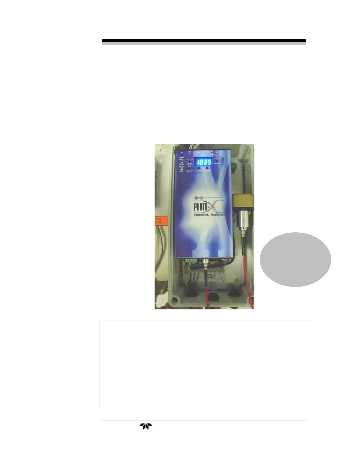
UV-Photo-X
OPERATING INSTRUCTIONS FOR
MODEL 6650B
UV-Photo-X Fluorescence Analyzer
P/N M6650
02/15/2006
ECO # xx-xxxx
DANGER
Toxic gases and or flammable liquids may be present in this monitoring system.
Personal protective equipment may be required when servicing this instrument.
Hazardous voltages exist on certain components internally which may persist for a
time even after the power is turned off and disconnected.
Only authorized personnel should conduct maintenance and/or servicing. Before
conducting any maintenance or servicing, consult with authorized
supervisor/manager.
Teledyne Analytical Instruments i
Page 2

Model 6650
Copyright © 2006 Teledyne Analytical Instruments
All Rights Reserved. No part of this manual may be reproduced, transmitted, transcribed,
stored in a retrieval system, or translated into any other language or computer language in
whole or in part, in any form or by any means, whether it be electronic, mechanical,
magnetic, optical, manual, or otherwise, without the prior written consent of Teledyne
Analytical Instruments, 16830 Chestnut Street, City of Industry, CA 91749-1580.
Warranty
This equipment is sold subject to the mutual agreement that it is warranted by us free from
defects of material and of construction, and that our liability shall be limited to replacing or
repairing at our factory (without charge, except for transportation), or at customer plant at
our option, any material or construction in which defects become apparent within one year
from the date of shipment, except in cases where quotations or acknowledgements provide
for a shorter period. Components manufactured by others bear the warranty of their
manufacturer. This warranty does not cover defects caused by wear, accident, misuse,
neglect or repairs other than those performed by Teledyne or an authorized service center.
We assume no liability for direct or indirect damages of any kind and the purchaser by the
acceptance of the equipment will assume all liability for any damage which may result from
its use or misuse.
We reserve the right to employ any suitable material in the manufacture of our apparatus,
and to make any alterations in the dimensions, shape or weight of any parts, in so far as
such alterations do not adversely affect our warranty.
Important Notice
This instrument provides measurement readings to its use r, an d serves as a tool b y whic h
valuable data can be gathered. The information provided by the instrument may assist the user
in eliminating potential hazards caused by his process; however, it is essential that all
personnel involved in the use of the instrument or its interface, with the process being
measured, be properly trained in the process itself, as well as all instrumentation related to it.
The safety of personnel is ultimately the responsibility of those who control process
conditions. While this instrument may be able to provide early warning of imminent
danger, it has no control over process conditions, and it can be misused. In particular, any
alarm or control systems installed must be tested and understood, both as to how they
operate and as to how they can be defeated. Any safeguards required such as locks, labels,
or redundancy, must be provided by the user or specifically requested of Teledyne at the
time the order is placed.
Therefore, the purchaser must be aware of the hazardous process conditions. The purchaser
is responsible for the training of personnel, for providing hazard warning methods and
instrumentation per the appropriate standards, and for ensuring that hazard warning devices
and instrumentation are maintained and operated properly.
Teledyne Analytical Instruments, the manufacturer of this instrument, cannot accept
responsibility for conditions beyond its knowledge and control. No statement expressed or
implied by this document or any information disseminated by the manufacturer or its
agents, is to be construed as a warranty of adequate safety control under the user’s process
conditions.
ii Teledyne Analytical Instruments
Page 3
UV-Photo-X
Safety Messages
Your safety and the safety of others is very important. We have provided
many important safety messages in this manual. Please read these
messages carefully.
A safety message alerts you to potential hazards that could hurt you
or others. Each safety message is associated with a safety alert symbol.
These symbols are found in the manual and inside the instrument. The
definition of these symbols is described below:
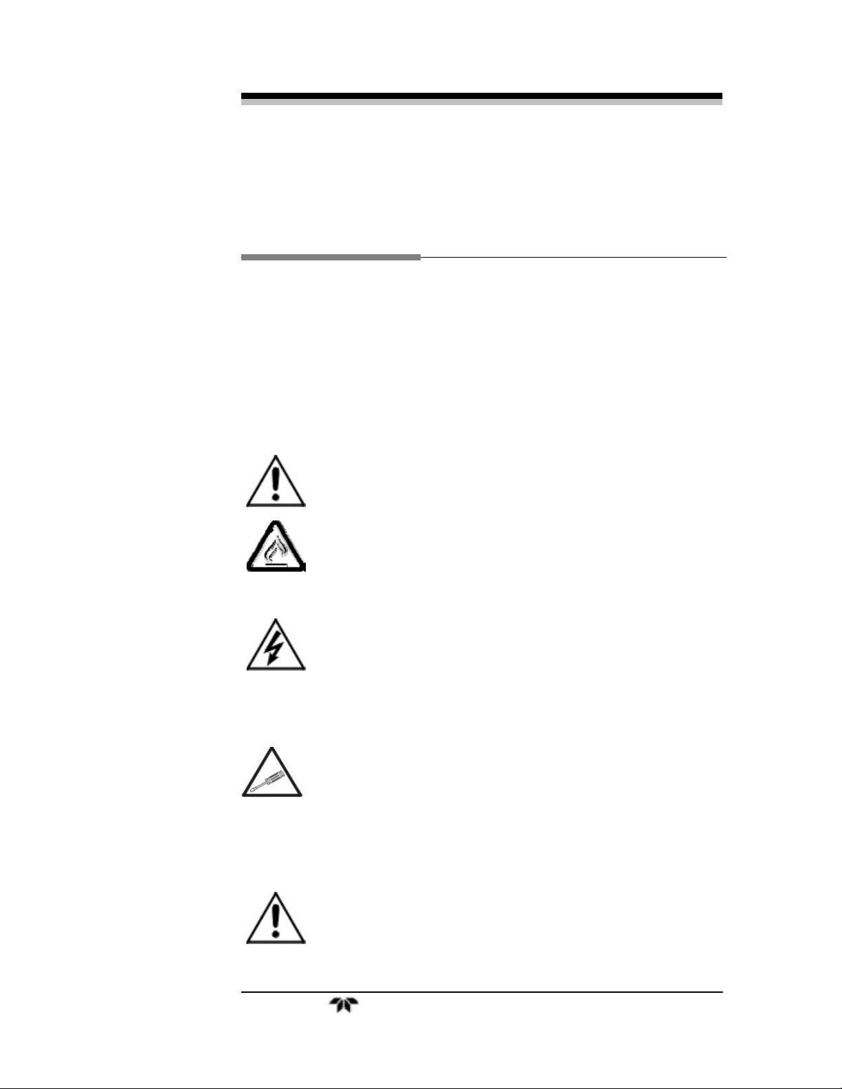
GENERAL WARNING/CAUTION: Refer to the instructions
for details on the specific danger. These cautions warn of
specific procedures which if not followed could cause bodily
Injury and/or damage the instrument.
CAUTION: HOT SURFACE WARNING: This warning is
specific to heated components within the instrument. Failure
to heed the warning could result in serious burns to skin and
underlying tissue.
WARNING: ELECTRICAL SHOCK HAZARD: Dangerous
voltages appear within this instrument. This warning is
specific to an electrical hazard existing at or nearby the
component or procedure under discussion. Failure to heed this
warning could result in injury and/or death from
electrocution.
Technician Symbol: All operations marked with this symbol
are to be performed by qualified maintenance personnel only.
NOTE: Additional information and comments regarding a
specific component or procedure are highlighted in the form
of a note.
CAUTION: THE ANALYZER SHOULD ONLY BE USED FOR THE
PURPOSE AND IN THE MANNER DESCRIBED IN
THIS MANUAL.
Teledyne Analytical Instruments iii
Page 4

Model 6650
IF YOU USE THE ANALYZER IN A MANNER OTHER
THAN THAT FOR WHICH IT WAS INTENDED,
UNPREDICTABLE BEHAVIOR COULD RESULT
POSSIBLY ACCOMPANIED WITH HAZARDOUS
CONSEQUENCES.
This manual provides information designed to guide you through
the installation, calibration and operation of your new analyzer. Please
read this manual and keep it available.
Occasionally, some instruments are customized for a particular
application or features and/or options added per customer requests.
Please check the front of this manual for any additional information in
the form of an Addendum which discusses specific information,
procedures, cautions and warnings that may be peculiar to your
instrument.
Manuals do get lost. Additional manuals can be obtained from
Teledyne at the address given in the Appendix. Some of our manuals are
available in electronic form via the internet. Please visit our website at:
www.teledyne-ai.com.
iv Teledyne Analytical Instruments
Page 5

UV-Photo-X
Table of Contents
Safety Messages ..........................................................................iii
Table of Contents..........................................................................v
List of Figures vii
Introduction ...................................................................................1
1.1 Theory of Operation 1
1.2 Filter Based Flurometer Description 2
Definition of Terms........................................................................4
2.1 Excitation Filter 4
2.2 Emission Filter 4
2.3 Measure Detector 4
2.4 Span Filter 4
2.5 Background Fluorescence 5
2.6 Sensitivity 5
2.7 Specificity 5
2.8 Signal-to-Noise Ratio 5
2.9 Signal-to-Background Ratio 6
2.10 Dynamic Range 6
2.11 Linearity 6
2.12 Process Background 6
2.13 Mode 1 Initialization 6
2.14 Mode 2 Initialization 7
Diagnostics & Controls.................................................................8
3.1 Front Panel Controls 8
Hardware Installation....................................................................9
4.1 Physical 9
4.2 Optical 9
4.3 Electrical 10
Teledyne Analytical Instruments v
Page 6

Model 6650
Setup & Operation....................................................................... 12
5.1 First Power-Up Following Installation 13
5.2 Application Engineering 14
5.3 Initialization for Process Monitoring: Mode 2 Operation 15
5.3.1 Case 1: Process monitoring following hardware
setup without application engineer 15
5.3.2 Case 2: Process monitoring without application
engineering 15
5.3.3 Case 3: Process monitoring following application
engineering 16
5.4 Initialization for Process Monitoring: Mode 1 Operation 18
5.5 Adjusting the Display 19
5.6 Adjusting the 20 mA Level 20
5.7 Adjusting the 20 mA Level 21
5.8 Diagnostics 22
5.8.1 Front Panel Lamp Diagnostics 22
5.8.2 Rectifying the Problem: Flashing Yellow Indicators 23
5.8.3 Rectifying the Problem: Red Indicators 24
Specifications.............................................................................. 26
6.1 General Measurement Specifications 26
6.2 Transmitter Specifications 27
6.3 Mechanical Specifications of Analysis Cell/Probe. 28
Appendix...................................................................................... 30
A-1 Application Engineering Assistance 30
A-1.1 Series 1 - Initializing the Unit and Determination of
the Probe/Analyzer Signal Level 30
A-1.2 Determination of the Probe/Transmitter
Fluorescence in a Non-Fluorescing Liquid: 32
A-1.3 Determination of the Process Fluorescence: 33
A-2 Notes 36
A-3 Recommended 2-Year Spare Parts List 37
Index............................................................................................. 38
vi Teledyne Analytical Instruments
Page 7

UV-Photo-X
List of Figures
Figure 1-1: Molecular Fluorescence Example.............................1
Figure 3-1: Photo-X Front Panel Controls...................................8
Figure 4-1: Top view of Flurometer............................................11
Teledyne Analytical Instruments vii
Page 8
Model 6650
DANGER
COMBUSTIBLE GAS USAGE
This is a general purpose instrument designed for usage in a
nonhazardous area. It is the customer's responsibility to
ensure safety especially when combustible gases are being
analyzed since the potential of gas leaks always exist.
The customer should ensure that the principles of operating
of this equipment are well understood by the user. Misuse of
this product in any manner, tampering with its components,
or unauthorized substitution of any component may
adversely affect the safety of this instrument.
WARNING
Since the use of this instrument is beyond the control of
Teledyne, no responsibility by Teledyne, its affiliates, and
agents for damage or injury from misuse or neglect of this
equipment is implied or assumed.
viii Teledyne Analytical Instruments
Page 9
UV-Photo-X Introduction
Introduction
1.1 Theory of Operation
The ability to monitor the concentration of an analyte in a process
stream is critical for accurate and reliable process control. There are
many techniques used to determine the analyte concentration of interest.
One of the most sensitive sensing techniques is molecular fluorescence.
Fluorescence occurs when a molecule absorbs light energy, either
ultraviolet or visible, and rapidly emits light, at some longer wavelength.
Fluorescence of this type is referred to as Stokes fluorescence.
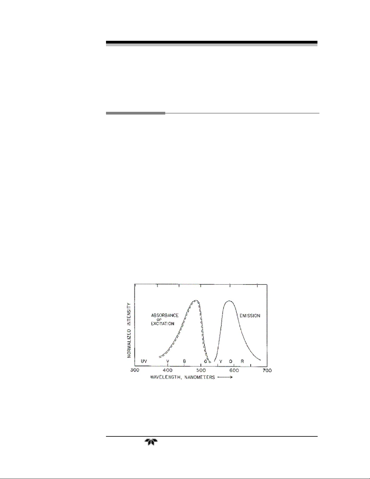
Fluorimetry characterizes the excitation and emission properties of the
molecular species. Figure 1-1 shows an example of the excitation and
emission spectrum from a hypothetical fluorophore.
Fluorimetry is concerned with two types of information: 1) The
(spectral) wavelength distribution, which is characteristic of the
electronic properties of the molecule, and 2) The intensity of the
fluorescence, which is typically correlated to the concentration of the
fluorescent molecule in the solution.
Figure 1-1: Molecular Fluorescence Example
Teledyne Analytical Instruments 1
Page 10

Introduction Model 6650
1.2 Filter Based Flurometer Description
The Fluorometer is a filter-based analyzer. The Fluorometer
measures the ability of the analyte of interest to absorb light in a narrow
spectral region and emit light at a longer wavelength. A filter-based
Fluorometer is a good choice when quantitative measurements are
desired for a specific analyte in process. Additionally, the Fluorometer
provides a relative measurement and can be calibrated with a known
concentration standard(s) or correlated to measurements using standard
laboratory methods resulting in a quantitative fluorescence.
A filter-based Fluorometer uses optical filters to provide specific
excitation or emission wavelengths wavelengths for molecular
fluorescence. In the Fluorometer the filters are located internal to the
transmitter and are specific to the application. Therefore, the
Fluorometer is a dedicated instrument for monitoring only one specific
analyte of interest. The filter sets used to configure the instrument are
specific to the analyte of interest. In order to monitor a new analyte of
interest, the user must return the Fluorometer to TIA for factory
reconfiguration. The Fluorometer can be used for both quantitative
measurements (determination of analyte concentration) and control
measurements (switching of valves once a fluorescence level is attained,
for example)
In brief, the Fluorometer works as follows: The light source
launches excitation light into a fiber optic cable. The fiber optic cable
transfers the excitation light to the Fluorescence probe mounted in the
process. The fluorescence probe launches light into the process sample,
and collects the molecular fluorescence (emission) from the sample. The
emission light is then transferred from the probe through fiber optic
cable to the analyzer. The emission light passes through an emission
filter in order to remove any residual excitation energy collected by the
fluorescence probe. The emission light then impinges a detector and the
fluorescence intensity is displayed on the analyzer.
Unlike many fluorescence units on the market, the Fluorometer
utilizes a xenon flash lamp to provide excitation energy. This lamp
allows the Fluorometer to be easily configured to meet any excitation
wavelength requirement with the appropriate filter selection across the
entire spectrum. The xenon flash lamp also has an extended lifetime
compared to other common UV sources (deuterium, mercury vapor,
etc.), which reduces the cost of ownership of the analyzer.
2 Teledyne Analytical Instruments
Page 11

UV-Photo-X Introduction
The remainder of this manual provides the user with the necessary
tools to operate the Fluorometer. In addition to standard operation
methods and procedures, a section detailing some application
development objectives (Appendix 1) has been provided to aid the user
in defining the parameters required to realize optimal process
monitoring.
Teledyne Analytical Instruments 3
Page 12

Definition of Terms Model 6650
Definition of Terms
2.1 Excitation Filter
The excitation filter is used to select the range of wavelengths, the
pass band, used to cause or excite the molecular fluorescence.
Wavelengths not in the pass band are rejected and ideally never reach
the sample. Removal of wavelengths outside the pass band minimizes
the possibly of false fluorescence readings due to detection of light from
the lamp which mimics the fluorescence signal.
2.2 Emission Filter
The emission filter is used to select the range of wavelengths, the
pass band, to be passed to the measure detector. Wavelengths not in the
pass band are rejected and ideally never reach the sample. It is critical
that the excitation wavelengths never reach the detector, since it will
respond to excitation light. Excitation light impinging the measure
detector results in increased residual background levels, which reduces
the dynamic range, the signal-to-noise ratio and the signal-to-blank ratio.
2.3 Measure Detector
The light detector is most often a photomultiplier tube, though
photodiodes are increasingly being used. The light passing through the
emission filter is detected by the photomultiplier or photodiode. The
light intensity, which is proportional to the analyte concentration, is
registered as a digital readout.
2.4 Span Filter
The span filter is used to check instrument operation. When a
fluorescence filter is employed the span filter fluorescence value is
dependent on the initialization method utilized and the standards used
during calibration. The span filter is used to verify instrument operation
and should not be used to calibrate the instrument.
4 Teledyne Analytical Instruments
Page 13

UV-Photo-Florescenceefinition of Terms
2.5 Background Fluorescence
The fluorescence signal due to the probe/analyzer optical
configuration, stray light, and fluorescence from the background
material.
2.6 Sensitivity
The ability of the analyzer to detect a given level of analyte
based on the molecular fluorescence from the analyte. The actual limits
of detection depend on the properties of the analyte measured and the
process conditions. Parameters such as pH, temperature, oxygen content,
and background solvent, to name but a few may dramatically alter the
fluorescence intensity measured. Typically, detection of parts-permillion (PPM) and parts-per-billion (PPB) analyte levels can be
detected. In general, fluorescent measurements are 1,000 to 500,000
times more sensitive than absorbance based photometric measurements.
Practically, sensitivity means the minimum analyte concentration that
can be measured above background fluorescence in the process.
2.7 Specificity
The ability of the analyzer to monitor one specific analyte in a
mixture of background materials without interference from the
background materials. In absorbance based photometric measurements,
interference problems are common since many materials absorb light,
making it difficult to isolate the targeted analyte in a complex mixture.
However, Fluorometers are highly specific and less susceptible to
interferences because fewer materials exhibit molecular fluorescence.
Furthermore, if background materials do absorb and emit light, it is rare
that they will emit the same wavelength of light as the analyte of
interest.
2.8 Signal-to-Noise Ratio
Signal refers to the emission collected by the fluorescence probe
and monitored by the analyzer using the internal span filter. Noise
refers to the output from the instrument’s electronics, which is present
whether or not sample is being read and any collection of errant
wavelengths not removed by the optical filters. Noise is measured by
placing the fluorescence probe in air and in complete darkness (no stray
light). For process monitoring, the signal-to-noise ratio is not as
important as the signal-to background ratio.
Teledyne Analytical Instruments 5
Page 14

Definition of Terms Model 6650
2.9 Signal-to-Background Ratio
Signal refers to the emission collected from a sample with known
analyte concentration by the fluorescence probe and monitored by the
analyzer. Background refers to the process liquid containing no analyte
of interest and any stray light present in the system. The signal-tobackground ratio should be calculated during the application engineering
phase of the project. Knowing this ratio will help determine when the
stray light level changes and/or the background material fluorescence
properties change. Refer to Appendix 1 for additional details.
2.10 Dynamic Range
Dynamic range refers to the range of concentrations an
instrument can read, from the minimum to the maximum detectable.
The minimum detectable concentration is determined by signal-to-noise
and signal-to-background ratios. The maximum detectable concentration
is determined by the compound’s chemistry and by factors such as
instrument sensitivity ranges, fluorescence (quantum) efficiency,
specificity of optical filters, etc.
2.11 Linearity
Fluorescence intensity is typically directly proportional (linear) to
concentration. There are, however, factors that affect this linear
relationship. For example, variations in temperature, pH, dissolved
oxygen content, stray light, turbidity, variation in the chemical
composition of the background, etc. can dramatically affect the linearity
of the fluorescence response. Practically, the linearity of the
measurement is determined during the application engineering phase of
the project. Refer to Appendix 1 for details.
2.12 Process Background
The liquid solution used to transport or sustain the analyte of
interest in the process. This solution has all the chemical constituents
found in the process except the analyte of interest.
2.13 Mode 1 Initialization
Mode 1 initialization is a method for setting up the Fluorometer for
process monitoring. Mode 1 initialization is used to setup the
Fluorometer when the fluorescence intensity versus analyte
6 Teledyne Analytical Instruments
Page 15

UV-Photo-Florescenceefinition of Terms
concentration and the background fluorescence of the process have
been characterized. Mode 1 initialization must be performed while the
fluorescence probe is immersed in the calibration (reference) sample.
In Mode 1, fluorescence calibration is based on a process sample
with a known analyte concentration. The background material for this
sample must be the process background material. The fluorescence from
the calibration (reference) sample is then used to set the midpoint of the
fluorescence scale. During Mode 1 initialization, the zero fluorescence
level is set electronically to 0 counts (display value), the midpoint range
is set to 1000 counts (display reading after initialization), and the upper
limit of the range is set to twice the midpoint value (1999 display value).
Section 5 provides details the procedure for Mode 1 initialization.
NOTE: If the Fluorescence of the process has not been
characterized, Mode 2 initialization must be performed first
followed by an application engineering study, refer to
Appendix 1 for guidance.
2.14 Mode 2 Initialization
Mode 2 initialization is a method for setting up the Fluorometer for
process monitoring and/or application engineering studies. Mode 2
initialization is used to setup the Fluorometer when the fluorescence
intensity versus analyte concentration and the background fluorescence
of the process are unknown (but the excitation/emission matrix has
been fully characterized by our application engineering
department). Characterization of the fluorescence response as a
function of analyte concentration can be performed onsite, refer to
Appendix 1 for details, or at TI in the Applications Development lab.
In Mode 2, fluorescence calibration is set electronically.
Initialization may be performed while the fluorescence probe is
immersed in any process sample, although for simplicity TI recommends
using the process background material without any analyte of interest.
This sample is commonly called the zero or blank sample. During Mode
2 initialization, the zero fluorescence level is set electronically to 0
counts (display value) and the upper limit of the range is set to the 1999
display value. Section 5 provides details the procedure for Mode 2
initialization.
Teledyne Analytical Instruments 7
Page 16

Diagnostics & Controls Model 6650
Diagnostics & Controls
3.1 Front Panel Controls
The front panel controls are used to adjust the display, Zero,
initialization of the transmitter, and the 4-20mA output. Figure 3-1,
below, identifies the position of each of these controls.
1)
11)
10)
1) Initialization Preset Switch 9) Fine zero adjustment
2) Span check LED indicator 10) Reference detector switch
8)
9)
5)
7) 6)
Figure 3-1: Photo-X Front Panel Controls
2)
3)
4)
3) User mode indicator LED 11) Measure detector status
4) User mode span adjustment
5) Digital display
6) 20mA adjustment
7) 4mA adjustment
8) Course zero adjustment
8 Teledyne Analytical Instruments
Page 17

UV-Photo-X Hardware Installation
Hardware Installation
In addition to the physical, optical, and electrical installation
requirements of the Fluorometer it is recommended that the transmitter
be placed in a clean, dry area of the plant. If the local area of where the
electronics are mounted exceeds our upper temperature limit of 115°F, it
is recommended that the transmitter be moved or purged with plant air
that can act to remove heat from building up inside of the enclosure.
Please follow the outlined sections below as a guideline to
installing the Fluorometer in your plant environment.
4.1 Physical
1) Bolt the Fluorometer in place using mounting screws to a secure,
rigid surface.
2) Run required electrical wiring for instrument power and 4-20
mA output signals.
Run required dry and oil free purge air for the unit.
3) Run fiber optic cable in conduit or other appropriate protective
measure as desired.
4) Install probe in sensing location, making sure there are no leaks
and the probe has been fully tested for process conditions such as
temperature and pressure.
4.2 Optical
To remove or install the fiber optic cables from the
probe, the following needs to be done:
1) Unscrew the optic cables from the bottom of the light source
and the control unit.
2) Unscrew the liquid tight connector’s 1 ¾” nut which is
connected to the conduit from the other part.
3) Remove the probe bracket from wherever it’s attached to.
Teledyne Analytical Instruments 9
Page 18

Hardware Installation Model 6650
4) Unscrew the 1 9/16” nut from the probe. Do this by holding the
probe by hand and using a wrench on the nut.
5) Once the nut has been removed from the probe, the two unions
with the SMA fiber-optic connectors connected are exposed and
the cable can be removed.
6) Remove the protective boots from the SMA 905 connectors on
the fiber optic cable.
7) Clean the fiber ends using a lint free cotton swab dipped in
either spectroscopic grade isopropyl alcohol (IPA, also referred
to as 2-propanol) or methanol. Spectroscopic grade acetone can
also be used, but may delaminate the cotton from the swab by
dissolving the binding agent.
8) Connect the fiber optic cable
a. One end of one cable to the probe,
b. The distal end of the cable above to the source, and
SIGNAL IN port.
c. The second fiber gets connected to the outlet end of the
probe and it’s distal end gets connected to the SMA-905
fitting on the bottom of the transmitter labeled; “Measure
Channel Input”
9) Finger tighten the SMA 905 connectors. DO NOT use a wrench
to tighten the nut.
4.3 Electrical
1) Connect the power and ground to the terminal strip mounted
located below the luorometer.
2) Connect the 4-20 mA signal output line to the terminal strip
located below the Fluorometer.
3) If required, connect the remote span filter insertion control line
to the terminal strip located below the Fluorometer. The unit is
supplied with a jumper on the terminal strip, which is the
configuration for at instrument span filter insertion.
4) It is best if the unit is not initially powered up until after the
initial optical setup is completed.
10 Teledyne Analytical Instruments
Page 19

UV-Photo-X Hardware Installation
Figure 4-1: Top view of Flurometer
Teledyne Analytical Instruments 11
Page 20

Setup & Operation Model 6650
Setup & Operation
The Fluorescence transmitter is designed to monitor the
fluorescence signal from a laboratory or process stream. Under certain
conditions the fluorescence range of the sample is well defined and can
be verified with standard reference materials such as zero and span
solutions of know concentrations. However, this is not always the case
when measuring fluorescence and is addressed in the design of the
product via the mode selection.
There are two modes which can be employed for calibration/set up
of the transmitter, namely mode 1, or mode 2. Typically when the user
does not know what the expected range or the fluorescent value of the
samples use mode 2 initialization. Mode 2 initialization requires the
initialization preset switch (refer to Figure 3-1 ) be held for >8 seconds.
In the mode 2 initialization the ratio of the fluorescent value to the
excitation value needs to be spanned properly in the display, since this
value is unknown the transmitter arbitrarily set to 20 times the original
ratio. This is done with or without the probe in a sample. Once a real
sample is available, the transmitter range may be determined. Once the
transmitter range is known, a calibrated range, using mode 1 operation,
may be set.
Mode 1 is used to set the full scale range of the unit but it does so
by splitting the range at the midpoint of the full scale. That is to say that
if you had a sample of concentration of X the full scale would be 2X.
The calibration sample would read 1000 counts and have a 12mA
output. If on the other hand you wanted a full scale range of X you
would have to dilute your sample to X/2 to get a full scale of X.
The display output is in arbitrary count units. To convert the
arbitrary unit to relevant engineering units the 4-20mA output must be
manipulated using an external device. The transmitter display cannot be
set to relevant engineering units. Additionally, the user can adjust the
output display over the full scale range once it has been established.
Note: The above readings are all based on defined excitation and
emission wavelengths for the given sample or intended
application.
12 Teledyne Analytical Instruments
Page 21

UV-Photo-X Setup & Operation
5.1 First Power-Up Following Installation
1) The Fluorometer comes preconfigured from the TIA factory
using the supplied fiber optic cable and fluorescence probe.
Preconfiguration at TIA involves application specific filter sets
and optimization of detection capabilities. Preconfiguration
should insure turnkey operation upon arrival.
2) Make sure that the probe is located in complete darkness. Stray
light in the measurement area will result in an increased baseline
response level and will limit the effective monitoring capabilities
of the instrument.
3) Immerse the fluorescence probe in a process sample. TIA
recommends that the setup sample be the process
background.
4) Make sure that all fiber optic cables are properly connected
5) Make sure that all electrical connections to the transmitter have
been made according to the wiring diagram.
6) Power up the unit.
7) Allow the lamp to flash for a minimum of 1 hour before
completing the rest of the initialization sequence.
8) After lamp warm-up and stabilization, the REF DET LED
should have a steady green output. The MSR DET LED may
have a flashing yellow, flashing green, or a solid green output.
The indicator LEDs are located to the left of the display along
the outer edge of the Fluorometer housing.
9) Perform Mode 2 initialization
a) Press the INT PRESET, located in the upper left hand corned
of the Fluorometer, for at least eight (8) seconds. Please see
Section 2 for a description of Mode 2 operation.
b) Both the REF and MSR DET LEDs exhibit solid green or
flashing green output. c) The value on the display is
fluorescence level in the process. If the sample is the
background material, this is your background fluorescence
level.
Teledyne Analytical Instruments 13
Page 22

Setup & Operation Model 6650
d) Insert the span filter using the SPN CHK button located
on the upper end of the Fluorometer housing. When the
filter is in place, the FLTR-IN LED will change from
green to red.
e) Wait 2 minutes for the output to stabilize and the unit will
read an upscale value.
f) Both the REF and MSR DET LEDs should have solid
green or flashing green output.
g) If the indicator LED color does change color, refer to the
Diagnostics section below.
h) Depress the SPN CHK button to remove the filter from
the beam path. The FLTR-IN indicator will change from
red to green.
i) Wait 2 minutes for the output to stabilize and the unit
should display the background fluorescence level.
j) Both the REF and MSR DET LEDs should have solid
green or flashing green output.
k) The unit is now ready for either application engineering
studies or process monitoring.
10) During initial setup, there is no need to adjust the 4 mA, 20
mA or display settings. These adjustments should be made
only during the setup for application engineering or process
monitoring.
NOTE: The First Power-Up Following Installation sequence
should be completed anytime the unit has been powered
down for an extended time period (> 7 days)
5.2 Application Engineering
Refer to Appendix 1 for suggested application Engineering
suggested procedures. Unless this has been supplied by TIA you will
have to establish a relationship between your samples and the response
from the instrument. You will have to develop a compound specific
calibration curve and you will have to determine your limit of detect
ability, and dynamic range.
14 Teledyne Analytical Instruments
Page 23

UV-Photo-X Setup & Operation
5.3 Initialization for Process Monitoring: Mode 2
Operation
Mode 2 process monitoring is used whenever the user wants to
forego the application engineering sequence or when the application
engineering results indicate that Mode 2 operation is sufficient to meet
the monitoring requirements of the user.
The outline below is the steps for initialization of the unit:
5.3.1 Case 1: Process monitoring following
hardware setup without application engineer
Setup was completed during the First Power-Up Following
Installation sequence; no additional setup is required, although
adjustments to the display, 4 mA and 20 mA levels may be desired.
Instructions for altering these levels are located below. TIA strongly
suggests that no changes to the 4 mA, 20 mA and display levels
occur until after the user has collected data on the process
fluorescence.
5.3.2 Case 2: Process monitoring without
application engineering
This case is valid when the user desires to monitor the process
without performing application engineering studies, the process has
changed slightly and the user wants to monitor the changes without
performing a complete application engineering study, or to determine if
full application engineering studies are warranted.
The steps outlined below assumes that the hardware was initialized
properly (see above) and that the Fluorometer has been functioning
properly since installation.
1) The fluorescence probe must be immersed in the background
material.
2) Perform Mode 2 initialization
a) Press the INT PRESET, located in the upper left hand corned
of the Fluorometer (refer to Figure 3-1), for at least eight (8)
seconds. Please see Section 2 for a description of Mode 2
operation.
Teledyne Analytical Instruments 15
Page 24

Setup & Operation Model 6650
b) Both the REF and MSR DET LEDs should have solid
green or flashing green output.
c) The value on the display is fluorescence level in the
process. If the sample is the background material, this is
your background fluorescence level.
d) Insert the span filter using the SPN CHK button located
on the upper end of the Fluorometer housing. When the
filter is in place, the FLTR-IN LED will change from
green to red. Refer to Figure 3-1.
e) See page 18 for discussion on span filter.
f) Both the REF and MSR DET LEDs should have solid
green or flashing green output.
g) If the indicator LED color does change color, refer to the
Diagnostics section below.
h) Depress the SPN CHK button to remove the filter from
the beam path. The FLTR-IN indicator will change from
red to green.
i) Wait 2 minutes for the output to stabilize and the unit
should display the background fluorescence level.
j) Both the REF and MSR DET LEDs should have solid
green or flashing green output.
k) The unit is now ready for process monitoring.
3) There is no need to adjust the 4mA and 20 mA levels for process
monitoring, since the presence of analyte will move the
fluorescence level upward from the background level.
4) Instructions for adjusting the 4mA, 20 mA and display levels are
given below.
5.3.3 Case 3: Process monitoring following
application engineering
This case is valid when the user has determined that Mode 2
monitoring is sufficient to meet the monitoring goals in process. This is
the simplest monitoring method since no calibration standard is
required.
16 Teledyne Analytical Instruments
Page 25

UV-Photo-X Setup & Operation
The steps outlined below assume that the hardware was initialized
properly and that the Fluorometer has been functioning properly since
installation.
1) The fluorescence probe can be immersed in any process sample.
Since application engineering has been performed, the user has
generated a calibration curve such that the fluorescence level can
be immediately correlated to an analyte concentration.
2) Perform Mode 2 initialization.
a) Press the INT PRESET, located in the upper left hand corned
of the Fluorometer, for at least eight (8) seconds. Please see
Section 2 for a description of Mode 2 operation.
b) Both the REF and MSR DET LEDs exhibit solid green or
flashing green output.
c) The value on the display is fluorescence level of the process.
d) Using the span filter to verify unit operation. This step is not
required since the process fluorescence has been
characterized, but is recommended to verify Fluorometer
operational viability.
i. Insert the span filter using the SPN CHK button located
on the upper end of the Fluorometer housing. When the
filter is in place, the FLTR-IN LED will change from
green to red. Refer to Figure 3-1.
ii. Wait 2 minutes for the output to stabilize and the unit
should read an upscale value.
iii. Both the REF and MSR DET LEDs should have solid
green or flashing green output.
iv. If the indicator LED color does not change color, refer to
the Diagnostics section below.
v. Depress the SPN CHK button to remove the filter from
the beam path. The FLTR-IN indicator will change from
red to green.
vi. Wait 2 minutes for the output to stabilize and the unit
should display the background fluorescence level.
vii. Both the REF and MSR DET LEDs should have solid
green or flashing green output.
Teledyne Analytical Instruments 17
Page 26

Setup & Operation Model 6650
viii. The unit is now ready for process monitoring.
3) There is no need to adjust the 4mA and 20 mA levels for process
monitoring, unless desired by the user. Instructions for adjusting
the 4mA, 20 mA and display levels are given below
5.4 Initialization for Process Monitoring: Mode 1
Operation
Mode 1 process monitoring is used once a calibration curve has
been developed (see Appendix 1). This initialization sequence requires
that the user generate a process sample with a known analyte
concentration, which is used to calibrate the fluorescence scale.
Outlined below are the steps for initialization of the unit, assuming
that hardware installation and start-up has occurred and that the
Fluorometer is working properly:
1) The fluorescence probe must be immersed in a calibration
sample.
2) Perform Mode 1 initialization.
a) Press the INT PRESET, located in the upper left hand
corned of the Fluorometer , for at least three (3) seconds,
but no longer than five (5) seconds.
b) Both the REF and MSR DET LEDs should have solid
green or flashing green output.
c) Wait 2 minutes for the reading to stabilize.
d) The value on the display should be 1000 ± 20 counts and
the 4-20 mA level should be 12.000 ± 0.164 mA.
e) Insert the span filter using the SPN CHK button located
on the upper end of the Fluorometer housing. When the
filter is in place, the FLTR-IN LED will change from
green to red.
i. Wait 2 minutes for the output to stabilize and the
unit should read an upscale value.
ii. Both the REF and MSR DET LEDs should have
solid green or flashing green output.
iii. If the MSR indicator LED color does change color,
refer to the Diagnostics section below.
18 Teledyne Analytical Instruments
Page 27

UV-Photo-X Setup & Operation
iv. Depress the SPN CHK button to remove the filter
from the beam path. The FLTR-IN indicator will
change from red to green.
v. Wait 2 minutes for the output to stabilize and the
unit should display the calibration sample level.
vi. Both the REF and MSR DET LEDs should have
solid green or flashing green output.
f) The unit is now ready for process monitoring.
3) There is no need to adjust the 4mA and 20 mA levels for process
monitoring, since the presence of analyte will move the
fluorescence level along the calibration curve determined by the
user during the application engineering studies.
Instructions for adjusting the 4mA, 20 mA, and display levels are
given below if the user wants to adjust the levels.
5.5 Adjusting the Display
The display values can be adjusted for both Mode 1 and Mode 2
operation using the following instructions. For clarity the directions
describe changing the display following a Mode 1 initialization since the
Fluorometer, will display a value easily correlated to a process variable.
Figure 3-1 can be used to locate all the adjustment points described.
1) Immerse the probe in a process sample, preferably with a
known analyte concentration and therefore fluorescence
level.
2) The Fluorometer is always configured in USER MODE.
The display is displaying the fluorescence intensity in
arbitrary counts.
3) The display and 20 mA output levels are interrelated in
USER MODE. Consequently adjusting the display value
alters the 4-20 mA output signal level.
4) The display adjustment is the right of the display. The
adjustment is designated USR SPAN CONTROL
5) Display Adjustment (Mode 1 initialization) a) The
calibration sample is being monitored b) If the display
reading is close to 1000 counts (off by <100 counts) use the
Teledyne Analytical Instruments 19
Page 28

Setup & Operation Model 6650
USR SPAN CONTROL to adjust the display to read 1000
counts
6) Adjusting the display level after Mode 2 initialization is not
recommended
5.6 Adjusting the 20 mA Level
The zero level or 4 mA level can be adjusted at any time during the
monitoring process; however, it is strongly recommended that the 4 mA
level be adjusted when the fluorescence probe is immersed in the
background sample. The Fluorometer/probe combination exhibits a
fluorescence signal so even if the background material does not
fluoresce and there is not stray light in the measurement area there will
be a non-zero fluorescence measured. It is not critical that the
background fluorescence be zero, only that the background fluorescence
level is stable. Furthermore, the zero fluorescence level is set
electronically in both Mode 1 and Mode 2, not by process samples.
The following procedure is followed for both Mode 1 and Mode 2
initialization. Refer to Figure 3-1 for the locations of the adjustments
discussed.
1) Immerse the probe in a process sample, preferably the
background material with no analyte of interest.
2) Monitor the 4-20 mA signal using an appropriate meter.
3) Note the display reading.
4) Depress and hold the ZRO CHK button. This disconnects
the Fluorometer output from the detector circuitry of the
Fluorometer, which allows the 4 mA level to be set.
5) The display should read approximately 0000 ± 20 counts
and the 4-20 mA signal should be 4.000 ± 0.164 mA.
a) Adjusting the Display
i. Changing the display once ZRO CHK is depressed
will only alter the display level observed once ZRO
CHK is no longer depressed.
ii. The display adjustments are located to the left of the
display. If the display reading is close to 0000 counts
(<100 counts off) use the FINE ZERO CONTROL to
adjust the display.
20 Teledyne Analytical Instruments
Page 29

UV-Photo-X Setup & Operation
iii. If the display is >100 counts off use the COURSE
ZERO CONTROL to bring the reading near 0000 and
then fine tune the adjustment with the FINE ZERO
CONTROL.
b) Adjusting the 4 mA level.
i. The 4 mA adjustment is located below the display.
ii. Adjust the 4 mA level until the 4-20 mA signal is in
the 4.000 ±0.164 mA range
6) Release ZRO CHK button.
7) Note the display reading.
8) If the displayed reading changed by more than 20 counts,
reinitialization of the Fluorometer may be required for
accurate process monitoring. This is especially true for
Mode 1 operation where the calibration sample is set to a
specific fluorescence level.
9) It is not recommended that the zero level be altered for
Mode 2 initialization.
5.7 Adjusting the 20 mA Level
The 20 mA level can be adjusted for both Mode 1 and Mode 2
operation using the following instructions. Although the display and 20
mA levels are interrelated in USER MODE, adjustment of the 20 mA
level will not alter the display value. For clarity the directions describe
changing the 20 mA level following a Mode 1 initialization since the
Fluorometer, will display a value easily correlated to a process variable
Causes and solution keys:
Figure 3-1 can be used to locate all the adjustment points described.
1) Immerse the probe in a process sample, preferably with a
known analyte concentration and therefore fluorescence
level.
2) Monitor the 4-20 mA signal using an appropriate meter.
3) The Fluorometer is configured in USER MODE. The
display is displaying the fluorescence intensity in arbitrary
counts.
Teledyne Analytical Instruments 21
Page 30

Setup & Operation Model 6650
4) Note that any adjustment of the display levels will adjust the
20 mA level; therefore only adjust the 20 mA level after
setting the display.
5) The 20 mA adjustment is located below the display.
6) With the display reading 1000 counts the 20 mA signal
should be 12.000 mA
7) Adjust the 20 mA level until the 4-20 mA output is 12.000
mA.
8) Adjusting the 20 mA level after Mode 2 initialization is not
recommended.
5.8 Diagnostics
5.8.1 Front Panel Lamp Diagnostics
The MSR DET STATUS and REF DET STATUS lamps show the
relative signal energy present. When the LED’s change their colors or go
from constant to flashing this is an indication that the energy levels on
the appropriate detector has changed. Reasons for changes in the LED
output could be feed stock changes, filter attenuation, flow cell/probe
fouling or broken fibers.
The signal levels on the measure and reference channels are shown
by the MSR DET STATUS and REF DET STATUS lamps. (Refer to
Figure 3-1)
1) If both lamps show steady or flashing green, the energy
levels are sufficient and no change is needed.
2) If either lamp shows red, the photomultiplier of that channel
is overloaded.
3) If either lamp shows steady orange, the energy level of that
channel is at the low limit for the high measurement range.
Cables, filters, and cell should be checked and the energy
level should be improved, if possible, to give a steady green
indication.
4) If either lamp shows flashing orange, the energy level of
that channel is below the reliable measurement range. The
optical system must be revised, to bring the lamp indication
back to steady green, if possible.
22 Teledyne Analytical Instruments
Page 31

UV-Photo-X Setup & Operation
Flashing Yellow Detector LED: there is not enough light striking
the detector.
Red detector LED: there is to much light intensity on the detector.
5.8.2 Rectifying the Problem: Flashing Yellow
Indicators
1) Verify that the lamp is emitting light.
a) Remove the fiber optic cable from the lamp launch
assembly.
b) Place a white piece of paper or business card in from
of the lamp launch assembly. The card will exhibit
either a bluish purple or reddish flashing spot when
operating properly.
c) If no flashing is occurring contact TIA for additional
instructions
d) If flashing is observed, reconnect the fiber optic
cable to the lamp launch assembly
2) Verify that the fiber optic cable is securely attached to lamp,
probe and analyzer.
3) If Steps 1 and 2 are not sufficient, then the probe must be
removed from the measurement location and checked for
cleanliness
a) Remove the fiber optic cables from the probe
b) Remove the probe from the measurement area
c) Visually examine the probe for deposits. NOTE: a
visual inspection will only detect gross deposits.
d) Clean the probe tip using a solvent known to remove
the process background material and the analyte of
interest. Gently rub the optical surface with a damp
lint free cloth or cotton swab to remove deposits.
e) Rinse the probe tip using spectroscopic grade
isopropyl alcohol (IPA or 2-propanol) or methanol
to remove residual cleaning solvent.
Teledyne Analytical Instruments 23
Page 32

Setup & Operation Model 6650
f) Dampen a cotton swab or lint free cloth with the
rinse solvent and gently rub the optical surface.
g) Air-dry the probe for a few minutes.
h) Reinsert into the process and follow the required
initialization sequence (see above)
4) If Step 1-3 are not sufficient to return the Fluorometer to
operation, contact TIA for assistance.
5.8.3 Rectifying the Problem: Red Indicators
If there has been a major change in the probe installation or process
piping. Most likely, there is a stray light leak into the system. Verify
that the monitoring location is in complete darkness. If stray light is not
present at the monitoring location, contact TIA for assistance.
24 Teledyne Analytical Instruments
Page 33

UV-Photo-X Setup & Operation
Teledyne Analytical Instruments 25
Page 34

Specifications Model 6650
Specifications
6.1 General Measurement Specifications
1) Measurement method.
OPTICAL METHOD: Fluorescence
Analysis type: Front Surface Fluorescence
2) Sampling Wavelengths.
Excitation: UG11
Reference: 328nm bandpass
Emission: 420 nm UVLP
3) Optical path length.
NA.
4) Sample.
Mode 1 Calibration
Salcon Water = 455 counts
5ppm in water = 1000 counts
Water + span filter = OFF-SCALE
5ppm + span filter = OFF-SCALE
Mode 2 Calibration
Salcon Water = 044 counts
5ppm in water = 081counts
Span filter = 279 counts
5) Optical span filter.
Span Calibration value: see above
Span Filter Type: SS-KFLY-5
26 Teledyne Analytical Instruments
Page 35

UV-Photo-X Specifications
6.2 Transmitter Specifications
1) Configuration.XSource Reference Through Media
Reference.
Application specific settings
Operation mode Display format XXXX
specified 4mA = (unspec, field settable)
specified 20mA = (unspec, field settable)
2) Optical specifications.
a) Lamp.
Xenon Flash Lamp, Life: 3-5 years
b) Detectors.
PMT
Spectral range: UV 190-690 nm
3) Electrical specifications. ( Tungsten Halogen, X Flash
Lamp)
a) Power Requirements 24VDC(IEC connector)
Current Requirements; LED ~332mA Tungsten
Halogen ~728.5mAmA (24VDC)
Consumption:
LED 8 W Tungsten Halogen ~17.5W (24VDC)
b) Output signal: Isolated 4-20mA sourced output
Permissible loop resistance
500 ohms for customer use
c) Span calibration:
Remote trigger via normally closed contact (must remove the
jumper on the top of the Photo-X unit for remote triggering)
Teledyne Analytical Instruments 27
Page 36

Specifications Model 6650
4) Mechanical specifications of the Transmitter.
a) Main Transmitter unit.
Size: 105mm (4.4") x 245mm (9.5") x 88.9mm (3.5")
b) (OPTIONAL) NEMA 12/13 Enclosure. NEMA
12/13 Enclosure dimensions for sub-rack:
Size: mm (") x mm (") x mm (")
c) (OPTIONAL) NEMA 4x Enclosure. NEMA 4x
Enclosure dimensions for sub-rack:
Size: 381mm (15") x 355.6mm (14") x 203.2mm (8")
d) Lamp Dimension
Size: 45mm (1.8") x 138mm (5.4") x 85mm (3.3")
6.3 Mechanical Specifications of Analysis
Cell/Probe.
1) Cell type
Fiber Optic Front Surface Probe P/N 3502
2) Probe window material:
Sapphire
3) Probe body material:
Hastelloy C
4) Probe sealing material:
Viton o-ring seal for sapphire windows on probe
5) Probe pressure rating:
5000 psig
6) Probe temperature rating:
200°C
7) Assembled probe dimensions:
1/2” diameter shaft X 12.5” (to tip of SMA fitting)
28 Teledyne Analytical Instruments
Page 37

UV-Photo-X Specifications
8) Probe cleaning method
The fiber optic probe can be supplied with an automatic
retraction device that will prevent the customer from
shutting down the process in order to clean and calibrate
(with standard solutions) the probe. This optional device
will be supplied when an automatic method of cleaning
and/or an automatic method of calibration is required.
9) Extractive calibration method
Fill the brown plastic bottle with standard solution and
insert the probe into the brown plastic calibration bottle with
the swagelok fitting in the cap. Replace the standard
solution with a different concentration when desired.
10) Calibration Solution
5 ppm (v/v) EPA #2 in Salcon produced water. To maintain
calibration level with homogenization of the calibration
solution a setting of 40 (dial) with an output of 30 was
required with circulation level maintained for ~15 minutes.
Teledyne Analytical Instruments 29
Page 38

Appendix Model 6650
Appendix
A-1 Application Engineering Assistance
TIA's customers and partners working to validate our hardware for
specific applications, where the application engineering and
development work is undertaken at customer locations, may use this
document as a guide. This document is a suggested procedure only and
is based on an understanding of the hardware operational requirements,
not detailed knowledge of the specific application parameters and
variables. These suggested experiments are the first sequence only,
additional experiments will probably be required to fully characterize
the process fluorescence.
A-1.1 Series 1 - Initializing the Unit and
Determination of the Probe/Analyzer Signal
Level
The following initialization sequence assumes that application
engineering is being performed in a laboratory setting. The hardware
installation is assumed to be minimal (unit is placed on a bench).
1) Mount the fluorescence probe on a lab stand. The probe
comes from TIA with a black PVC cap over the sensing tip.
Leave this cap in place. Initialization of the unit will occur
with the cap in place. The initialization sequence below will
result in determination of the probe/analyzer residual
fluorescence level.
2) Connect the electrical, 4-20 mA output and fiber optic
cables as described in Section 4.
3) Power-up the Fluorometer.
4) Allow the system to operate a minimum of one hour before
completing the rest of the initialization instructions.
5) After lamp warm-up and stabilization, the REF DET LED
should have a steady green output. The MSR DET LED
should have either a solid green or flashing green output.
30 Teledyne Analytical Instruments
Page 39

UV-Photo-X Appendix
The indicator LEDs are located to the left of the display
along the outer edge of the Fluorometer housing. Refer to
Figure 3-1. If the indicators are non-green, refer to the
Diagnostics section in Section 5. Preconfiguration at the
TIA factory should eliminate the occurrence of non-green
indicators.
6) Perform Mode 2 initialization
a) Press the INT PRESET, located in the upper left
hand corned of the Fluorometer (refer to Figure 3-1),
for at least five (8) seconds.
b) Both the REF and MSR DET LEDs exhibit solid
green or flashing green output.
c) The value on the display is the fluorescence level
due to the probe/analyzer configuration. Record this
value for later analysis. Table 1 below provides an
example of how to organize measurement data.
d) Insert the span filter using the SPN CHK button
located on the upper end of the Fluorometer
housing. When the filter is in place, the FLTR-IN
LED will change from green to red.
e) Wait 2 minutes for the output to stabilize and the
unit should read an upscale value.
f) Both the REF and MSR DET LEDs should have
solid green or flashing green output.
g) If the indicator LED color does change color, refer
to the Diagnostics section below.
h) Depress the SPN CHK button to remove the filter
from the beam path. The FLTR-IN indicator will
change from red to green.
i) Wait 2 minutes for the output to stabilize and the
unit should display residual fluorescence level of the
probe/analyzer configuration.
j) Both the REF and MSR DET LEDs should have
solid green or flashing green output.
k) The unit is now ready for either application
engineering studies or process monitoring.
Teledyne Analytical Instruments 31
Page 40

Appendix Model 6650
7) During the application engineering process there is no need
to adjust the 4 mA, 20 mA or display settings.
A-1.2 Determination of the Probe/Transmitter
Fluorescence in a Non-Fluorescing Liquid:
1) Prepare the measurement area to be used for liquid testing.
a) For lab analysis a wide mouth amber bottle, which has
been wrapped with tape works as a measurement vessel.
The cap of the bottle needs to be equipped with a feed
through that will hold the probe. (Use P/N 53FCAL
calibration bottle/ fitting).
b) In the pilot system, mount the fluorescence probe in the
monitoring location using the appropriate connections.
c) For both installations it is imperative that there is no stray
light in the system and the probe is in complete darkness.
2) If the Fluorometer is on, turn off the unit. Remove the protective
cap from the probe tip and mount the probe in the testing
location, which has been filled with a non-fluorescing material
with solution characteristics as close to the process background
as possible. It is critical that the solution is completely non-
fluorescing, so that only the refractive index difference between
air and liquid sample may alter the fluorescence level. Ultra pure
water, RO water or DI water are probably good choices for the
test material.
3) Power-up the unit and wait about 5 minutes. The power down
does not affect the initialization settings.
4) After lamp stabilization, the REF DET LED should have a
steady green output. The MSR DET LED should have either a
solid green or flashing green output. If the indicators are nongreen, refer to the Diagnostics section in Section 5.
5) Record the fluorescence level on the display
6) Insert the span filter.
a) Wait 2 minutes for the output to stabilize
b) Record the fluorescence level due to span filter insertion.
c) Remove the span filter.
32 Teledyne Analytical Instruments
Page 41

UV-Photo-X Appendix
d) Wait 2 minutes for the output to stabilize and the unit
should display residual fluorescence level of the
probe/analyzer configuration.
7) Calculate the difference between the air and liquid fluorescence
levels. The difference is due to the change in refractive index
between air and the liquid sample.
A-1.3 Determination of the Process Fluorescence:
This experimental sequence is the first step in characterizing the
process fluorescence. The Fluorometer will use the Mode 2 initialization
used for the previous experimental measurements.
For laboratory analysis using a small vessel (recommend, P/N
53FCAL), the analyst will need to collect pull samples from the process
which covers the entire range of analyte concentrations. It is
recommended that at least six process samples be analyzed. The first
sample will be the process background material and should not contain
analyte of interest.
For pilot process testing, it is critical that the initial process liquid
be background material with no analyte of interest. The process can then
be run normally and monitored.
The steps outlined below are based on discrete sample analysis, but
can be easily modified for continuous process monitoring.
1) If the unit is not on, power-up the unit and allow warming up for
at least 1 hour. If the unit has been running, just begin the
sequence.
2) Place the background material in the sample vessel, wait 2
minutes and record the fluorescence level. This reading is your
background fluorescence and is a combination of the
fluorescence properties of the background material, stray light
and the probe/ analyzer fluorescence.
3) The dynamic range of the instrument, for the application
engineering sequence can be determined at this time using the
following equation:
Range Multiplier = 1999/Display Value
4) Gently wipe the probe tip with a lint free cotton swab or cloth
dampened with the process background material and gently rub
Teledyne Analytical Instruments 33
Page 42

Appendix Model 6650
the optical surface. This insures that each sample is tested
without fouling of the optical surface. This step is not possible in
the pilot system.
5) In sequence measure the fluorescence from each of the process
samples. Make sure to wait 2 minutes after placing the probe in
contact with the solution before recording the fluorescence
reading. Make sure to clean the probe tip after each sample.
6) If none of the samples off scales the unit (a 1 on the display in
the fourth digit), then using the data obtained plot the
fluorescence intensity versus analyte concentration for the data.
Determine the linearity of the output response and a possible
calibration sample.
7) If one or more samples off scaled the unit (a 1 on the display in
the fourth digit), then additional application engineering
sequences are required. Most likely a Mode 1 initialization study,
with the highest on scale sample used as the calibration sample.
The initialization sequence for Mode 1 is located in Section 5.
8) Once the process fluorescence has been characterized and the
calibration procedure determined repeat the experimental series
using the desired initialization mode to verify that the correct
monitoring approach has been selected.
34 Teledyne Analytical Instruments
Page 43

UV-Photo-X Appendix
Table 1: Data organization
Series 1: Air and Liquid Probe/Analyzer Fluorescence Level
Material
(Air, Liquid, Solid)
Probe/Transmitter
Fluorescence
Span Filter Fluorescence
Series 2: Process Sample Analysis
Sample Number
0
1
2
3
4
5
6
Analyte
Concentration
Measured Fluorescence
Series 3: Monitoring verification using selected calibration
(initialization) procedures.
Sample Number
0
1
2
3
4
5
6
Analyte
Concentration
Measured Fluorescence
Teledyne Analytical Instruments 35
Page 44

Appendix Model 6650
A-2 Notes
1) Convert 4-20mA output to counts;
Where X=mA output
(X-4/16)1999 = Counts
2) Convert 4-20mA output to engineering units;
(X-4/16) max value = Max Engineering Unit
The maximum engineering unit value should be 2x the
calibration sample value (mode 2 operation) or the sample with a
mode 1 fluorescence reading of 1999 counts.
3) Power Failure
Power failures <5 minutes in duration do not require unit
recalibration.
Power failures>5 minutes and <15minutes may require
recalibration. Verify fluorescence reading prior and after failure
is similar. The level of agreement is at the desertion of the
operator.
4) TIA utilizes two types of span filters; Metallic film ND filters are
used when fluorescent filters are not available for the application
specific excitations and emission wavelengths. The neutral
density filter reduces the measured signal bay a fixed percentage
whenever employed. For example, an ND may have a 70% pass
so if the process reading is 980 counts, inserting the span filter
will result in a reading of 686 counts (nominal).
5) Generally, the ref detector LED should always be solid green,
although flashing green is acceptable. Generally, in zero
fluorescencent material the measure detector LED should be
yellow, or flashing green Generally, in process or calibration
solution the measure detector LED should be flashing green or
solid green.
A solid red detector indicates to much signal intensity. Unit
must be returned to factory for evaluation.
A flashing yellow LED on either detector is a low signal level
and unit must be returned to factory for evaluation.
36 Teledyne Analytical Instruments
Page 45

UV-Photo-X Appendix
A-3 Recommended 2-Year Spare Parts List
Model 6650
QtyP/NDescription
2 CP2421 Fiber Optic Cables, 2M ea.
1 A674 Model 53F UV Fluorescence
Transmitter
1 P1323 Power Supply
1 M276 Meter 1/8 Din
1 P1334 Hastelloy C Florescence Probe
Note: Orders for replacement parts should include the part
number (if available) and the model and serial number
of the instrument for which the parts are intended.
Orders should be sent to:
TELEDYNE Analytical Instruments
16830 Chestnut Street
City of Industry, CA 91749-1580
Phone (626) 934-1500, Fax (626) 961-2538
Web: www.teledyne-ai.com
or your local representative.
Teledyne Analytical Instruments 37
Page 46

Index BDS 3000
Index
address, 36, See company address
caution sign, iii
combustible gas warning, viii
company address. See company
address
copyright, ii
electronic component location, 6
flowrate, 4
front panel, 8, 10
manuals, additional, iv
safety information, iii
spare parts listing, 36
specifications, 29
Teledyne address, 36
troubleshooting, 20
warning sign, iii
warranty, ii
web address, 36
website address, iv
38 Teledyne Analytical Instruments
 Loading...