

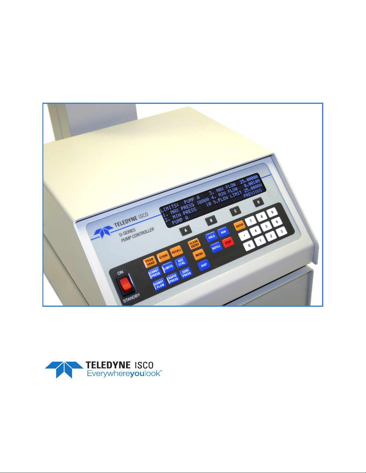
D-Series Pumps
Installation and Operation Guide
Part #69-1243-969 of Assembly #60-1243-998
Copyright © 2013. All rights reserved, Teledyne Isco
Rev. F, July 2018


Foreword
This instruction manual is designed to help you gain a thorough understanding of the operation of
the equipment. Teledyne ISCO recommends that you read this manual completely before placing
the equipment in service.
Although Teledyne ISCO designs reliability into all equipment, there is always the possibility of a
malfunction. This manual may help in diagnosing and repairing the malfunction.
If a problem persists, call or e-mail Teledyne ISCO technical support for assistance. Simple
difficulties can often be diagnosed over the phone. For faster service, please have your serial
number ready.
If it is necessary to return the equipment to the factory for service, please follow the shipping
instructions provided by technical support, including the use of the Return Material
Authorization (RMA) specified. Be sure to include a note describing the malfunction. This will
aid in the prompt repair and return of the equipment.
Teledyne ISCO welcomes suggestions that would improve the information presented in this
manual or enhance the operation of the equipment itself.
Teledyne ISCO is continually improving its products and reserves the right to change
product specifications, replacement parts, schematics, and instructions without notice.
Contact Information
Customer Service
Phone: (800) 228-4373 (USA, Canada, Mexico)
Fax: (402) 465-3022
Email: ISCO CSR@teledyne.com
Technical Support
Phone: Toll Free (800) 775-2965 (Syringe Pumps and Liquid Chromatography)
Email: IscoService@teledyne.com
Return equipment to: 4700 Superior Street, Lincoln, NE 68504-1398
Other Correspondence
Mail to: P.O. Box 82531, Lincoln, NE 68501-2531
Email: IscoInfo@teledyne.com
(402) 464-0231 (Outside North America)
EAR-Controlled Technology Subject to Restrictions Contained on the Cover Page.

Warnings and Cautions
The lightning flash and arrowhead within the triangle is a warning
sign alerting you to “dangerous voltage” inside the product.
The exclamation point within the triangle is a warning sign alerting
you to important instructions in this manual.
D Series Syringe Pumps
Warnings, Cautions, and Notices
Symboles de Sécurité
Ce symbole signale la présence d’un danger d’électrocution.
Ce symbole signale l’existence d’instructions importantes
relatives au produit dans ce manuel.
i
D Series Syringe Pumps
Warnings, Cautions, and Notices
Warnungen und Vorsichtshinweise
Der gepfeilte Blitz im Dreieck ist ein Warnzeichen, das Sie vor
„gefährlichen Spannungen“ im Inneren des Produkts warnt.
Das Ausrufezeichen in Dreieck ist ein Warnzeichen, das Sie
darauf aufmerksam macht, daß wichtige Anleitungen zu diesem
Handbuch gehören.
Advertencias y Precauciones
Esta señal alerta sobre la presencia de alto voltaje en el interior
del producto.
Esta señal le advierte sobre la importancia de las instrucciones
del manual que acompañan a este producto.
ii
D Series Syringe Pumps
Warnings, Cautions, and Notices
“To prevent damaging the instrument or injuring yourself, it is
absolutely necessary that you understand everything in English, above
all, technical terms, before operating the instrument. Otherwise, it is
necessary for you to receive complete instruction from someone
qualified who understands both the instrument and English very well.”
“Um eine Beschädigung des Gerätes oder eine Gefährdung des
Anwenders zu vermeiden ist es notwendig, daß dieser vollstandig die
englische Sprache und die technischen Bezeichnungen beherrscht.
Oder der Anwender muß von einer Person eingeübt werden, die bereits
vorher dieses Gerät bedienst hat.”
“Pour empêcher dommage à l’instrument ou blesser vous-même, il faut
absolument que vous compreniez tout en anglais, surtout les termes
techniques, avant d’actionner l’instrument. Autrement, il faut que vous
receviez l’instruction parfaite d’une personne très compétente qui
comprend bien les deux l’instrument et anglais.”
“Para prevenir cualquier daño en el instrumento o en el operador, es
necesario que el usuario comprenda perfectamente el lenguaje inglés y
las términos técnicos intrínsecos, o bien ser formado por una persona
que haya trabajado ya previamente con este instrumento.”
“For a forhindre skade på instrumentet eller operatøren er det
nødvendig at brukeren har full forståelse for det engelske sprak og
tekniske uttrykk Ellers må brukeren få opplæring av en person, som
kan engelsk, for instrumentet tas i bruk.”
“För att förhindra skade på instrumentet eller operatören, år det
nötvändigt att användaren har fullständiga kunskaper i det engelska
språket och dess tekniska termer, eller utbildas av en person, som
tidigare brukat instrumentet.”
“For at undgå skade på produktet eller på brugeren er det nødvendigt
at brugeren til fulde forstår det engelske sprog for at forstå den
tekniske formulering i den engelske manual. I modsat fald skal
brugeren modtage træning, inden apparatet tages I drift.”
iii
D Series Syringe Pumps
Warnings, Cautions, and Notices
Laitteelle tai käyttäjälle aiheutuvien vahinkojen välttämiseksi on
tärkeää, että käyttäjä hallitsee englannin kielen ja englantilaiset
tekniset termit tai on saanut käyttöopastuksen englantia osaavalta
henkilöltä.
“Per evitare danni allo struménto od incidenti all’operatore, é
necessario che l’utilizzatore abbia una completa conoscensza della
lingua inglese oppure che venga istruita da una persona che abbia
utilizzato precedentemente questo strumento.”
“Para impedir qualquer dano no aparelho ou ferimentos parao
operador, é necessario que o utilizador tenha um conhecimento
completo da lingua inglesa e dos respectivos termos técnicos, ou seja,
treinado por uma pessoa que tenha esse conhecimento, antes de
operar com este aparelho.”
“‘
”
С цел да избегне повреда на апаратурата или нараняване на
оператора е необходимо клиента добре да владее английски език и
техчническата терминолгия, която е използувана в описанието
или да бъде обучен от лице, което е вече работило с такъв апарат.
Figyelmeztetés! A készülék meghibásodásának valamint a kezelö
sérülésének megelözése érdekében a felhasználónak feltétlenül értenie
kell az angol nyelvet, ezen belül a müszaki kifejezéseket, vagy pedig a
használatba vételt megelözöen a készülék kezelésében már gyakarlott
személy által történö betanitás szükséges!
iv

D Series Syringe Pumps
Warnings, Cautions, and Notices
- EXPLOSION WARNING -
WARNING
Teledyne Isco D Series Pumps, SFX 2-10 and
SFX 220 Extractors are NOT EXPLOSION PROOF.
Teledyne Isco SFX System and D Series Syringe
Pump Safety Note when using a flammable fluid
The Teledyne Isco SFX system and syringe pumps must be placed within a properly operating vent hood (fume cupboard), when using ethane or any other flammable gas. Ensure that all SFE tubing connections are completely free of any gas
leaks by performing the leak test using CO
pump manual, Section 5 of the SFX 2-10 manual and Section 6 of the SFX 2-10,
220, and SFX 3560 manual). There must absolutely be NO gas leaks present before
introducing the flammable gas. In a temperature-stable, leak-free system, the flow
rate, as registered by the pump, should settle to a value below 0.01 ml/min after 15,
minutes during a static extraction.
(detailed in Section 2 of the D Series
2
Important: When using a Teledyne Isco extractor (either SFX 2-10, SFX
220, SFX 3560) be absolutely sure the built-in venting fan (a brushless
motor) is operating properly.
The Teledyne Isco D Series Syringe Pumps and the SFX units, use brush-type drive
motors. Minor modifications to the pumps may render them safer, especially in the
rare event of catastrophic piston seal failure. However, these modifications
will not make these pumps explosion proof.
•Remove the front and back cylinder covers located on the ball screw tower.
This will allow any escaped gas to quickly dissipate away from the pump cylinder area and to reduce the amount entering the motor compartment.
•Seal the syringe pump motor compartment with tape and purge it with a continuous flow of nitrogen (N
mulating an explosive mixture around the motor and relays.
•For further information, telephone Teledyne Isco at (800)775-2965, or fax
(402)465-3085 to consult the Teledyne Isco Service Department.
USE THE Teledyne Isco SFE SYSTEM AND SYRINGE PUMPS IN THESE
POTENTIALLY HAZARDOUS APPLICATIONS AT YOUR OWN RISK!
) gas. This will also reduce the possibility of accu-
2
5-97
v

D Series Syringe Pumps
Warnings, Cautions, and Notices
- AVERTISSEMENT D’EXPLOSION -
AVERTISSEMENT
Les pompes de Série ‘D’ Teledyne Isco et l’extracteur SFX 2-10,
SFX 220, et SFX 3560 ne sont pas à l’épreuve d’explosion!
Remarque de sûreté concernant l’usage d’un fluide inflammable avec les
pompes à seringue d’Isco Série ‘D’ et le système SFX.
Le système SFX et pompes à seringue Teledyne Isco doivent être placées à l'intérieur d’une hotte
chimique fonctionnelle, quand vous utilisez éthane C2H6, ou tout autre gaz inflammable.
Assurez-vous que toute la tuyauterie SFE est complètement scellée avec aucune fuite de gaz en exécutant une épreuve de fuite en utilisant du CO2. (Cette méthode est détaillée à la partie 2 du manuel de la pompe Série ‘D’et à la partie 2 du manuel SFX 2-10, SFX 220, et 3560.) Il faut absolument
qu'il n'y ait aucune fuite de gaz avant d'introduire le gaz inflammable au système. À partir d’un système à température stable et sans aucune fuite de gaz, la valeur du flot qui est indiqué par la
pompe, devrait se stabiliser à une valeur moins de 0,01 ml/min après 15 minutes, pendant une
extraction statique.
Important: Quand vous utilisez un extracteur Teledyne Isco SFX 2-10, SFX 220, et 3560,
soyez absolument certain que le ventilateur (du moteur sans brosses) fonctionne
correctement. Quand vous installez l'extracteur, assurez-vous qu'ilyaunespace vide de
15 centimètres au moins entre le mur et l'arrière de l'extracteur pour assurer ventilation
adéquate.
Le système SFE et les pompes de série 'D' utilisent les moteurs de courant continu. Ils possédent
des collecteurs et brosses qui produisent des décharges électriques (étincelles) entre eux quand les
moteurs fonctionnent normalement. Ces décharges, aussi bien que celles qui sont produites aux
contacts des relais pourraient faire exploser un mixture d'air et de gaz inflammable. De petites
modifications aux pompes peuvent les rendre moins dangereuses, surtout dans le cas rare d’une
panne catastrophique du joint d’étanchéité du piston. Cependant, il n’y a aucune modification
qui fera ces pompes à l’épreuve d’explosion!
• Enlevez les couvercles de devant et d'arrière du cylindre qui sont situés sur la tour de la
pompe. Cela permettra au gaz qui s'échappe de dissiper plus rapidement loin de la pompe et
réduira aussi la quantité de gaz qui entre dans le compartiment du moteur.
• Scellez le compartiment du moteur de la pompe avec un ruban adhésif et circulez un flot continu d'azote (N2) à l’intérieur du compartiment. Cela réduira aussi la possibilité d'accumuler
une mixture explosive autour du moteur et relais, où se trouvent la première possibilité des
étincelles électriques.
• Pour l'information supplémentaire, téléphonez gratuitement (800) 775-2965, ou télécopiez
(402) 465-3085 pour consulter le département de service technique.
UTILISEZ LE SYSTÈME SFE ET LES POMPES À SERINGUE TELEDYNE ISCO DANS TELLES
APPLICATIONS POTENTIELLEMENT HASARDEUSES Á VOS RISQUES ET PÉRILS!
vi
D Series Syringe Pumps
Warnings, Cautions, and Notices
WARNING:
PLEASE READ
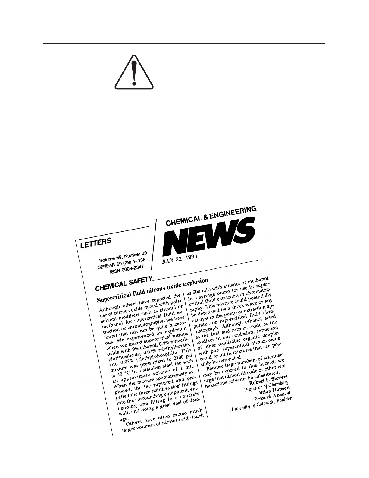
At the request of our Supercritical Fluid Extraction laboratory staff, we want our customers
to be aware of the potential hazards involved with supercritical fluid extraction. Oxidizing
gases, such as nitrous oxide, in contact with organic matrices or flammable modifiers, can
detonate under certain conditions. Likewise, flammable fluids, such as methane, under high
pressure conditions can present a hazard.
With concern for the safety of our customers, we have designed our extractors to be as safe as
possible. However, we do not recommend the use of our instrument with potentially explosive
reactions.
The letter below, which appeared in the July 22, 1991 edition of Chemical and Engineering
News, is reprinted with permission from Professor Robert E. Sievers and his colleagues at
the University of Colorado at Boulder. Even though they were not performing supercritical
fluid extraction, it details the problems their lab experienced using nitrous oxide under similar conditions. We add our support for their suggestion to use only carbon dioxide or other
less hazardous fluids for supercritical fluid extraction.
vii
D Series Syringe Pumps
Warnings, Cautions, and Notices
CAUTION:
Avoid spills! Liquids associated with this instrument may be classified
as carcinogenic, biohazardous, flammable, or radioactive. Should
these liquids be used, it is highly recommended that this application be
accomplished in an isolated environment designed for these types of
materials in accordance with federal state and local regulatory laws
and in compliance with your organization’s chemical/hygiene plan in
the event of a spill.
In all cases, when using Teledyne Isco instrumentation, prudence and
common sense must be used.
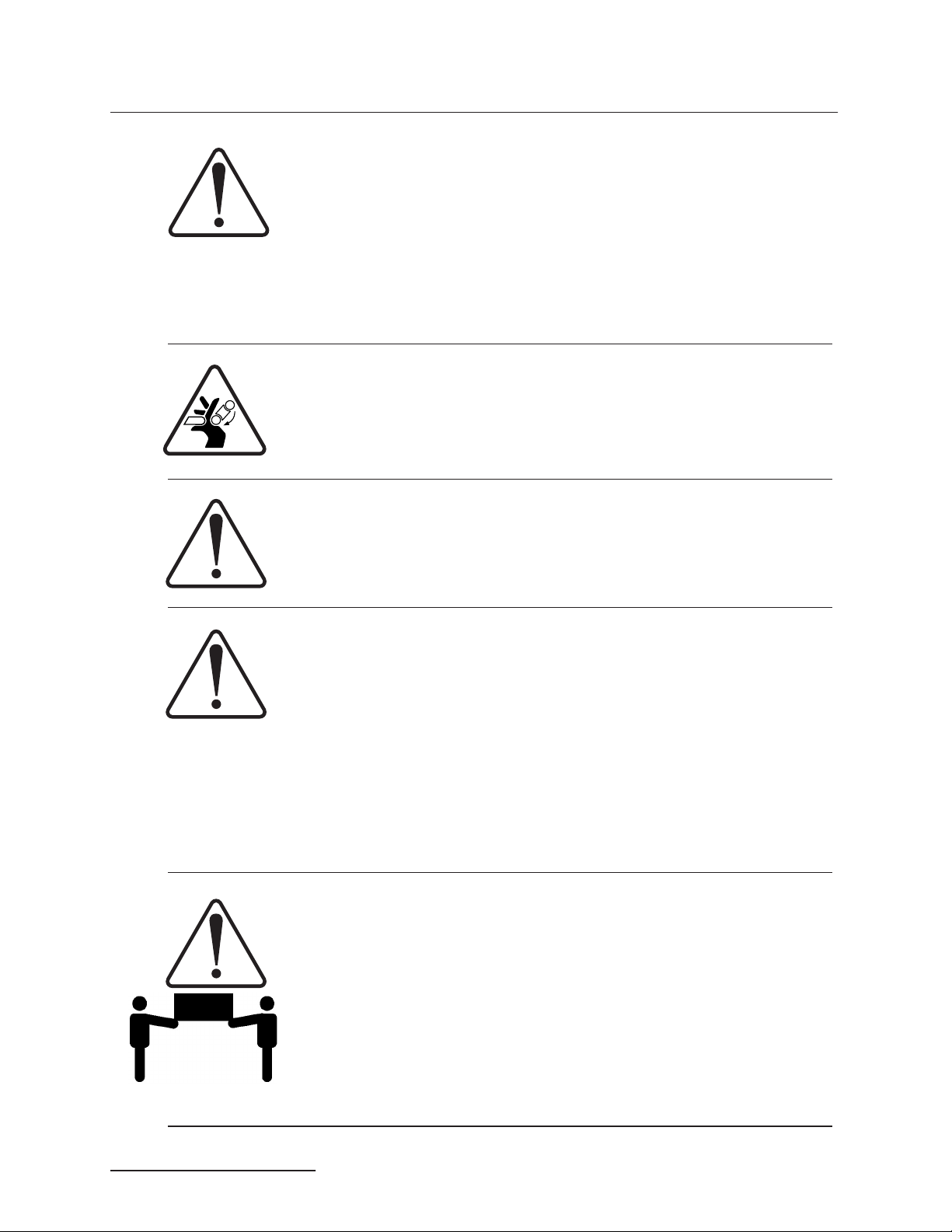
WARNING:
Pinch point. This symbol warns you that your fingers or hands will
sustain serious injury if you place them between the moving parts of
the mechanism near this symbol.
WARNING:
Avoid hazardous practices! If you use this instrument in any way not
specified in this manual, the protection provided by the instrument may
be impaired; this will increase your risk of injury.
CAUTION:
Liquids associated with this instrument may be classified as
carcinogenic, biohazardous, flammable, or radioactive. Should these
liquids be used, it is highly recommended that this application be
accomplished in an isolated environment designed for these types of
materials, in accordance with federal, state, and local regulatory laws,
and in compliance with your company’s chemical/hygiene plan in the
event of a spill.
In all cases, when using Teledyne Isco instrumentation, prudence and
common sense must be used.
WARNING:
Team lift.To reduce the risk of injury do not attempt to lift this
instrument independently. It is highly recommended that a team be
used when lifting this instrument.
viii
D Series Syringe Pumps
Warnings, Cautions, and Notices
AVIS: Éviter de répandre! Les liquides qui sont pompés dans cet
instrument peuvent être cancérigènes, hasards biologiques,
inflammables, ou radioactifs. Si vous devez utiliser ces liquides
hasardeux, il est très recommandé que vous le faites à l'intérieur
d'un environnement isolé conçu pour tels liquides. Cet
environnement isolé devrait être construit selon les règlements
fédéraux, provinciaux, et locaux, aussi que le plan de votre
organisation qui concerne l'évènement d'un accident avec les
matières hasardeuses. En tout cas, utilisez toujours
l'instrumentation d'Isco avec prudence et sens commun
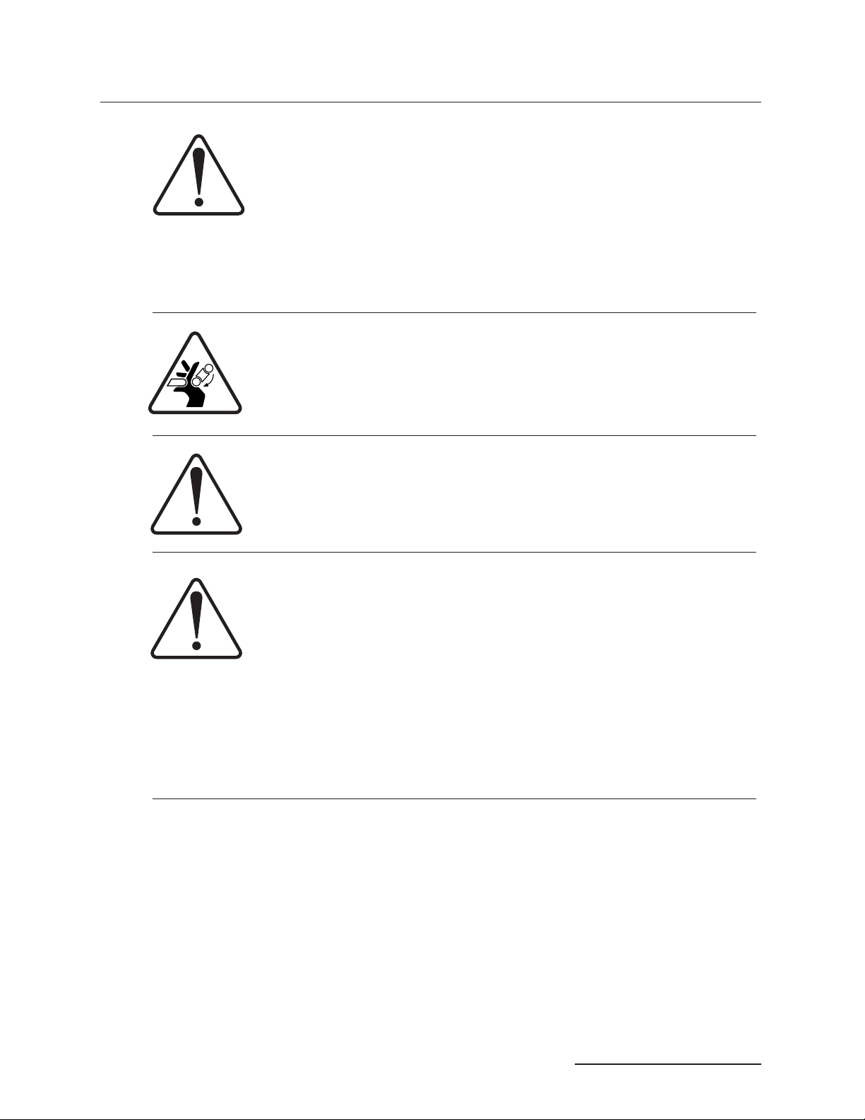
ATTENTION:
Risque de pincement. Ce symbole vous avertit que les mains ou les
doigts recevront une blessure sérieuse si vous les mettez entre les
éléments en mouvement du mécanisme près de ce symbole.
ATTENTION:
Éviter les usages hasardeux! Si vous utilisez cet instrument d’une
manière autre que celles qui sont specifiées dans ce manuel, la
protection fournie par l’instrument peut être affaiblie; cela augmentera
votre risque de blessure.
.
AVIS:
Les liquides qui sont analysés dans cet instrument peuvent être
cancérigènes, hasards biologiques, inflammables, ou radioactifs.
Si vous devez utiliser ces liquides hasardeux, il est très recommandé
que vous le faites à l'intérieur d'un environnement isolé conçu pour tels
liquides.
Cet environnement isolé devrait être construit selon les règlements
fédéraux, provinciaux, et locaux, aussi que le plan de votre
organisation qui concerne l'évènement d'un accident avec les matières
hasardeuses.
En tout cas, utilisez toujours l'instrumentation d'Isco avec prudence et
sens commun.
ix

D Series Syringe Pumps
Warnings, Cautions, and Notices
Commonly Ordered Replacement Parts for the
Description Part Number
Cylinder Seals General:
30D Seal Assembly 0-2068 bar 60-1249-128
30D Piston Assembly 0-2068 bar 60-1249-129
65D 0-1379 bar 202-9096-08
65DM 0-689.5 bar 202-9096-08
100DX/DM 0-689.5 bar 202-9090-75
260D 0-517.1 bar 202-9091-06
500D 0-258.6 bar 202-9091-56
500HPx 0-344.7 bar 202-9091-56
1000D 0-137.8 bar upper seal 202-9990-25
1000D 0-137.8 bar lower seal 202-9990-23
(For more information on seals, refer to Table 2-7.)
65D/30D
Inlet/Outlet fittings:
1
4" F250C Gland 209-0164-02
1
4" F250C Collar 209-0164-03
1
4" F250C Plug 209-0164-05
65DM
Inlet/Outlet fittings:
Valco -18" Nut 209-0169-27
1
8" Ferrule 209-0169-41
1
8" Plug 209-0166-80
1
8 –116" Tubing Reducer 209-0169-42
100DX/DM and 260D
Inlet/Outlet fittings:
Valco -18" Nut 209-0169-27
1
16" Nut 209-0094-07
1
8" Plug 209-0166-80
1
8 –116" Tubing Reducer 209-0169-42
500D
Inlet/Outlet fittings:
1
8" Tubing Connector to18" NPT 209-0161-01
1
8" NPT Plug 209-0168-00
1
8 –116" Tubing Reducer 209-0162-00
500 HPx
Inlet/outlet fittings:
3/
8" Tubing Connector to
3/
8" NPT Plug 209-016-813
D Series Syringe Pumps
3
8" NPT 209-016-100
x

D Series Syringe Pumps
Warnings, Cautions, and Notices
Commonly Ordered Replacement Parts for the
D Series Syringe Pumps
Description Part Number
1000D
Inlet/Outlet fittings:
1
4" NPT Plug 209-0168-09
1
4" NPT Connector to14" tubing 209-1063-36
Stainless Steel Tubing:
1
16"OD0.020" ID 004-7300-21
1
8"OD0.069" ID 004-7302-22
xi

D Series Syringe Pumps
Warnings, Cautions, and Notices
-NOTICE-
If you have ordered one of the following custom pumps from Teledyne
Isco, technical specifications for tubing and fittings listed in this manual
do not apply to your system.
Contact the factory for details about your custom pump.
Models:
65HP
260HP
500HP
500HV
500SP
xii

D Series Syringe Pumps
Table of Contents
Section 1 Introduction
1.1 About This Manual ..................................................1-1
1.2 Specifications .......................................................1-1
1.3 Unpacking ........................................................1-13
1.4 Controls and Indicators..............................................1-14
1.5 Electrical Connections...............................................1-18
1.5.1 Cabling .....................................................1-19
1.6 Preliminary Checkout...............................................1-21
Section 2 Fluid System Connections and Accessories
2.1 Introduction ........................................................2-1
2.2 Fluid System Connections ............................................2-1
2.2.1 Ports ........................................................ 2-1
2.2.2 Installation Tips ...............................................2-2
2.2.3 Tubing Requirements ..........................................2-2
2.2.4 Accessory Packages ............................................2-3
2.2.5 Installing the
2.2.6 Draining Overflow .............................................2-5
2.2.7 Cylinder Washing: Wash Gland ..................................2-5
2.2.8 Cylinder Washing: Nitrogen Purge ................................2-7
2.2.9 Flushing Pumps with External Transducers ........................2-8
2.3 Fluid Connection Accessories ..........................................2-8
2.3.1 Manual Refill Kit ..............................................2-8
2.3.2 Manual Outlet Valve Kit ........................................2-9
2.3.3 CO
2.3.4 In-Line Filter Package .........................................2-11
2.4 Temperature and Pressure Controls ...................................2-12
2.4.1 Cylinder Insulating Cover ......................................2-12
2.4.2 Temperature Control Jacket ....................................2-13
2.4.3 Back Pressure Regulation ......................................2-18
2.5 Seal Options.......................................................2-19
Cylinder Connection Package ...............................2-10
2
1
/16" Fittings (260D, 65DM, and 100DM/DX only) ........2-4
Section 3 Basic Programming and Operation
3.1 Introduction ........................................................3-1
3.2 General Controller Information ........................................3-1
3.2.1 Rates, Units, and Limits ........................................3-1
3.2.2 Programming Screens ..........................................3-1
3.2.3 Run Screens ..................................................3-2
3.2.4 Selecting Operating Parameters ..................................3-3
3.3 Main Menus........................................................ 3-3
3.4 Menu One..........................................................3-3
3.4.1 Flow and/or Pressure Units of Measure ............................3-3
3.4.2 Pump Selection
(if multiple pumps) ............................................3-4
3.4.3 Refill ........................................................3-4
3.4.4 Power Failure [STOP] ..........................................3-5
xiii

D Series Syringe Pumps
Table of Contents
3.5 Menu Two .........................................................3-5
3.6 Menu Three ........................................................3-8
3.7 Menu Four .........................................................3-9
3.8 Front Panel Keys...................................................3-10
3.9 Control of Multiple Pumps ...........................................3-13
3.10 Operating Modes ..................................................3-15
3.11 External Control ..................................................3-18
3.12 External Control: Analog ...........................................3-18
3.13 Remote RUN/STOP................................................3-21
3.14 Analog Flow Rate and Volume Output Options .........................3-22
3.4.5 System Reset (Restore Default Settings) ...........................3-5
3.4.6 Display Contrast ..............................................3-5
3.5.1 Serial Option .................................................3-6
3.5.2 Pump Status ..................................................3-6
3.5.3 External Control ..............................................3-6
3.5.4 Multiple Pumps ...............................................3-6
3.5.5 Total Volume Reset ............................................3-6
3.5.6 Valve ........................................................3-7
3.6.1 Poor Fill Alarm ................................................3-8
3.6.2 Diagnostic Menu ..............................................3-8
3.6.3 Pressure Calibration ...........................................3-8
3.6.4 Diff. Modes ...................................................3-9
3.6.5 Press. Integral ................................................3-9
3.6.6 Pressure Deadband ............................................3-9
3.7.1 Modbus Options ...............................................3-9
3.8.1 CONST PRESS and CONST FLOW .............................. 3-10
3.8.2 PRGM GRAD ................................................3-10
3.8.3 HOLD ......................................................3-10
3.8.4 RECALL ....................................................3-10
3.8.5 STORE .....................................................3-10
3.8.6 REFILL .....................................................3-10
3.8.7 LIMITS .....................................................3-10
3.8.8 RAPID PRESS ...............................................3-12
3.8.9 DISP .......................................................3-13
3.8.10 ACC CTRL .................................................3-13
3.8.11 ZERO PRESS ...............................................3-13
3.9.1 Multi-Pump Operation ........................................ 3-14
3.9.2 Independent Control of up to Four Separate Pumps .................3-14
3.10.1 Constant Flow ..............................................3-16
3.10.2 Constant Pressure ...........................................3-16
3.10.3 Dispense Mode ..............................................3-17
3.12.1 Wire connections ............................................
3.12.2 Preparation ................................................3-19
3.12.3 External Control for Refill .....................................3-19
3.12.4 Calculation Examples ........................................3-20
3.12.5 Setup ......................................................3-20
3.13.1 Wire Connections ............................................3-21
3.14.1 Voltage Analog Output .......................................3-22
3.14.2 Current Loop Output .........................................3-23
3-18
xiv
Section 4 Gradient Pumping for Pressure, Flow, and Concentration
Modes
4.1 Introduction ........................................................4-1
4.2 Connecting the System ...............................................4-2
4.2.1 Inlet Connections ..............................................4-4
4.2.2 Outlet Connections ............................................ 4-5
4.2.3 Dual Gradient System Connections ...............................4-6

D Series Syringe Pumps
Table of Contents
4.3 Single-Pump Gradient Programming ...................................4-8
4.4 Dual Pump Concentration Gradient Programming .......................4-10
4.5 Review, Revise, & Hold Options .......................................4-12
4.6 Program Conclusion ................................................4-12
Section 5 Continuous Flow Introduction, Installation, & Operation
5.1 Introduction ........................................................5-1
5.2 Continuous Flow Check Valves ........................................5-1
5.2.1 Check Valve Technical Specifications ..............................5-2
5.2.2 Dual Check Valve Installation ...................................5-2
5.2.3 Inlet Tubing ..................................................5-3
5.3 Continuous Flow Air Valves ...........................................5-7
5.3.1 Dual Air Valve Installation ......................................5-7
5.4 Continuous Flow Electric Valves ......................................5-13
5.4.1 Technical Specifications .......................................5-13
5.4.2 Dual Electric Valve Installation .................................5-14
5.5 User Supplied Valves ...............................................5-16
5.6 Continuous Flow Mode ..............................................5-17
5.6.1 Defining Operation ...........................................5-17
5.6.2 Constant Flow Mode ..........................................5-18
5.6.3 Constant Pressure Mode .......................................5-19
5.6.4 No Check Valve ..............................................5-20
5.6.5 To Run or Stop ...............................................5-21
5.6.6 Tips for Running Continuous Flow ...............................5-21
Section 6 Modifier Addition
6.1 Overview ..........................................................6-1
6.1.1 Installing the Kit ..............................................6-1
6.1.2 Modifier Mode Setup ...........................................6-4
6.1.3 Two Pump Operation ...........................................6-5
6.2 Programming .......................................................6-6
6.2.1 Mininum Modifier Pressure Setting ...............................6-7
6.2.2 Modifier Concentration .........................................6-7
6.3 Refilling ...........................................................6-8
Section 7 Modbus Configuration
7.1 Overview ..........................................................7-1
7.1.1 Modbus RTU .................................................7-1
7.1.2 Modbus TCP/IP ...............................................7-2
7.1.3 Modbus Configuration Options ...................................7-2
Section 8 Serial Interface
8.1 Overview ..........................................................8-1
8.2 Network Control and Communication ...................................8-2
8.3 USB Interface ......................................................8-3
8.4 Cabling for Serial Control .............................................8-3
8.4.1 One Controller ................................................8-3
8.4.2 Two Controllers (Compiler required) ..............................8-4
8.4.3 Three or More Controllers (Compiler required) ......................8-4
8.5 Serial Control Check List ............................................. 8-5
8.6 Controller Setup ....................................................8-5
8.6.1 Restore Defaults (if desired) .....................................8-5
8.6.2 Change Defaults ...............................................8-5
8.6.3 Verify Operation ..............................................8-6
xv

D Series Syringe Pumps
Table of Contents
8.7 User-written Software................................................8-6
8.8 Serial Commands for the D Series Pump ...............................8-20
Section 9 Pump Maintenance, Troubleshooting, and Servicing
9.1 Introduction ........................................................9-1
9.2 Maintenance Kits ...................................................9-3
9.3 General Cleaning....................................................9-4
9.4 Resetting the System ................................................9-4
9.5 Diagnostic Menu ....................................................9-6
9.6 Removing the Case Top...............................................9-9
9.7 Test Points........................................................9-11
9.8 Lubrication .......................................................9-12
9.9 Seal Cleaning and Replacement .......................................9-13
9.10 Wear Ring Cleaning and Replacement ................................9-17
9.11 Flushing the Cylinder ..............................................9-17
9.12 Overpressure Conditions ...........................................9-18
9.13 Motor Brushes ....................................................9-23
9.14 Calibrations ......................................................9-35
8.7.1 DASNET .....................................................8-6
8.7.2 Universal Driver from Teledyne Isco ..............................8-7
8.8.1 Get Status Command .........................................8-25
8.8.2 Gradient Download Command ..................................8-29
8.8.3 Gradient Upload Commands ....................................8-29
8.8.4 Range Command .............................................8-33
8.8.5 Error Messages .............................................. 8-34
9.1.1 Service Department ............................................9-2
9.1.2 How to Ship Returns ...........................................9-2
9.4.1 Basic Reset ...................................................9-4
9.4.2 Hard Reset ...................................................9-4
9.5.1 LCD TEST ................................................... 9-6
9.5.2 ANALOG INPUTS .............................................9-6
9.5.3 KEYPAD TEST ...............................................9-7
9.5.4 MOTOR CONTROL/LIMITS .....................................9-7
9.5.5 SERIAL TEST ................................................9-8
9.6.1 Controller Case Top Removal ....................................9-9
9.6.2 Pump Case Top Removal .......................................9-10
9.7.1 Power Supply (A1) ............................................9-11
9.7.2 Controller ...................................................9-11
9.8.1 Ball Nut ....................................................9-12
9.9.1 Piston Seal
(Excludes 30D) ...............................................9-14
9.9.2 Piston Seal Break-In (Aqueous seals only) .........................9-14
9.9.3 All other piston seals ..........................................9-15
9.9.4 Wiper Seal
(Excludes 30D) ...............................................9-15
9.11.1 Gas Solvent Changeover ......................................9-17
9.11.2 Liquid Solvent Changeover and Flushing ........................9-18
9.12.1 Shear Key ..................................................9-19
9.12.2 Replacement Using Installation Tool ............................ 9-20
9.12.3 Replacement Without Installation Tool ..........................9-21
9.12.4 Pump Bearings
(30D and 65DM Only) .........................................9-21
9.12.5 Completion of Shear Key Replacement ..........................9-22
9.13.1 Motor Brush Disassembly .....................................9-25
9.13.2 HPx Motor Brush Replacement ................................ 9-26
9.14.1 Pressure Transducer Calibration ...............................9-35
9.14.2 A/D Circuit Adjustment .......................................9-35
xvi

D Series Syringe Pumps
Table of Contents
9.14.3 Limit Sensor Adjustment .....................................9-35
9.14.4 Limit Sensor Calibration
(Excludes 30D) ...............................................9-39
9.14.5 30D Limit Sensor Calibration ..................................9-40
9.14.6 Electric Valve Motor Calibration ...............................9-41
Appendix A Replacement Parts
A.1 Replacement Parts ..................................................A-1
A.1.1 D Series Controller ............................................A-2
A.1.2 1000D Pump .................................................A-5
A.1.3 500D/DX Pump ...............................................A-9
A.1.4 500HPx Pump ...............................................A-13
A.1.5 100DM/DX and 260D Pumps ...................................A-16
A.1.6 65D Pump ..................................................A-20
A.1.7 65DM ......................................................A-33
A.1.8 Power Circuit Board ..........................................A-47
A.1.9 Analog Output Circuit Board ...................................A-51
A.1.10 Interface Circuit Board .......................................A-53
A.1.11 Dual Electric Valve Package ...................................A-55
A.1.12 Single Electric Valve Package .................................A-57
A.1.13 SST Dual Air Valve Package for 100/260D/500D ..................A-59
A.1.14 SST Dual Air Valve Package for 1000D ..........................A-61
A.1.15 Single Air Valve Package .....................................A-63
A.1.16 Dual Air Valve Package for 500HPx ............................A-65
A.1.17 Dual Check Valve Package for 100/260/500D .....................A-67
A.1.18 Dual Check Valve Package for 1000D ...........................A-69
A.1.19 Single Check Valve Package ...................................A-71
Appendix B Continuous Flow Introduction, Installation, and Operation for 30D
B.1 Introduction .......................................................B-1
B.2 Continuous Flow Air Valves...........................................B-1
B.2.1 Dual Air Valve Installation .....................................B-2
B.3 Continuous Flow Electric Valves .......................................B-4
B.3.1 Technical Specifications ........................................B-4
B.3.2 Dual Electric Valve Installation ..................................B-5
B.4 User Supplied Valves ................................................B-7
B.5 Continuous Flow Mode ...............................................B-8
B.5.1 Defining Operation ............................................B-9
B.5.2 Constant Flow Mode ..........................................B-10
B.5.3 Constant Pressure Mode .......................................B-10
B.5.4 No Check Valve ..............................................B-11
B.5.5 To Run or Stop ...............................................B-12
B.5.6 Tips for Running Continuous Flow ..............................B-12
B.6 Replacement Parts List .............................................B-14
B.6.1 30D Pump ..................................................B-14
B.6.2 30D Air Valve ...............................................B-17
B.6.3 30D Electric Air Valve ........................................B-19
List of Figures
1-1 260D flow rate range ...............................................1-11
1-2 500D flow rate range ...............................................1-11
1-3 500 HPx flow rate range ............................................1-12
1-4 1000D flow rate range ..............................................1-12
xvii

D Series Syringe Pumps
Table of Contents
1-5 Pump controller key functions ........................................1-14
1-6 Pump controller rear panel connectors .................................1-16
1-7 Pump rear panel connectors .........................................1-17
1-8 Pump front panel controls ...........................................1-18
1-9 Syringe pump cylinder cap: Attach to pressure transducer connector on back of
1-10 Connecting the pump and controller ..................................1-21
1-11 Status Screen ....................................................1-21
1-12 Menu 1 .........................................................1-22
1-13 Three pump stop menu ............................................1-23
1-14 Four pump stop menu .............................................1-23
2-1 Liquid system plumbing connections (30D on Left) ........................2-2
2-2
2-3 30D/65DFitting .....................................................2-4
2-4 Drain tube installation ...............................................2-5
2-5 Drain tube installation and wash gland connection ........................2-6
2-6 Purge connector installation ..........................................2-7
2-7 Refill kit installation ................................................2-9
2-8 Outlet valve package connection ......................................2-10
2-9 CO
2-10 In-line filter package ..............................................2-11
2-11 Cylinder insulation cover ...........................................2-12
2-12 System with temperature control jacket installed .......................2-13
2-13 Fluid fittings .....................................................2-14
2-14 Secure screws with the
2-15 Removing the cylinder cap with wrenches .............................2-16
2-16 Temperature control jacket installation ...............................2-17
2-17 Back pressure regulator ............................................2-18
2-18 Inside the pump cylinder: wetted materials ............................2-19
3-1 Menu 1 program selections ...........................................3-3
3-2 Units menu ........................................................3-3
3-3 Menu 2 program selections ...........................................3-5
3-4 Serial option menu ..................................................3-6
3-5 Total volume reset ..................................................3-6
3-6 Types of valves .....................................................3-7
3-7 Menu 3 program selections ...........................................3-8
3-8 Location of transducer midpoint value ..................................3-8
3-9 Limits menu ......................................................3-11
3-10 Limits setpoint (Max Press) menu ...................................3-11
3-11 Depiction of dispense mode sequence .................................3-17
3-12 External control for refill menu ......................................3-20
3-13 Button sequence for external control setup ............................3-21
3-14 Analog voltage output connection, rear panel ..........................3-22
3-15 Output range selection jumpers ..................................... 3-23
4-1 Pump inlet connections ..............................................4-4
4-2 Pump outlet connections .............................................4-5
4-3 Dual gradient system connections
4-4 Dual gradient connections: Detail ......................................4-7
5-1 Check valve package installation: 65DM/100D/265D/500D pumps ...........5-4
5-2 Check valve package installation: 1000D pump ...........................5-6
5-3 Air valve installation for 65DM, 100DM/DX, 260D, and 500D pumps ......... 5-9
5-4 Air valve installation for 500HPx pumps ...............................5-10
5-5 Air valve installation for 1000D pump .................................5-11
5-6 Air valve installation for 65D pump ...................................5-12
5-7 Electric valve installation ...........................................5-15
5-8 Keystrokes to specify valve type ......................................5-18
5-9 Keystrokes to reset volume totalizer ...................................5-18
5-10 Keystrokes to set up constant flow ...................................5-19
pump. ...........................................................1-20
1
/16" Tubing adapter for 30D/65D pumps ................................ 2-4
package installation ............................................2-11
2
1
/4” hex wrench ...............................2-15
(Inlet valves (A & C) are from refill valve kits) ...........................4-7
xviii

D Series Syringe Pumps
Table of Contents
5-11 Keystrokes to set up constant pressure ...............................5-19
5-12 Keystrokes to set up No Check Valve .................................5-20
5-13 Keystrokes to Run or Stop the pumps .................................5-21
6-1 Modifier addition kit installation (Two-pump configuration) ................ 6-2
6-2 Modifier addition kit installation (continuous flow) ........................6-3
6-3 Minimum modifier pressure screen .....................................6-7
7-1 RS-485 Connection ..................................................7-1
8-1 Serial network connection example - Single connection .................... 8-4
8-2 Serial network connection example - Dual connection ......................8-4
8-3 Get Status String “G” Command ......................................8-26
8-4 Get Status String “GG” Command ....................................8-26
8-5 Get All Status String “G&” Command .................................8-27
8-6 Get all status strings from four pump operation “G&2” Command ..........8-28
8-7 Gradient Download Commands - Single pump flow gradient ...............8-29
8-8 Gradient Download Commands - Two pump flow gradient .................8-30
8-9 Gradient Upload Commands - Single pump flow gradient .................8-31
8-10 Gradient Upload Commands - Two pump flow gradient ..................8-32
8-11 Upload Commands - Single pump pressure programming ................8-33
8-12 Range Serial Commands ...........................................8-33
9-1 500HPx fan filter ...................................................9-4
9-2 Accessing the diagnostic menu ........................................9-6
9-3 Analog Input diagnostic screen ........................................9-6
9-4 Optical sensor, interrupted by flag (bottom sensor shown, rear tower cover plate re-
moved) ........................................................... 9-7
9-5 Serial connection to a computer .......................................9-8
9-6 Controller case top screws (2 of 4 shown) ...............................9-10
9-7 Pump case top screws (2 of 4 shown) ...................................9-10
9-8 Gear train lubrication and motor drive service ..........................9-12
9-9 Break-in procedure for aqueous seals (Drawing does not apply to the 30D) . . . 9-15
9-10 Accessing the shear key ............................................9-20
9-11 Shear key replacement .............................................9-20
9-12 30D and 65DM Bearing set ......................................... 9-22
9-13 30D and 65DM Shear key replacement ...............................9-22
9-14 D Series motor brush replacement ...................................9-24
9-15 Location of motor brushes ..........................................9-24
9-16 Length of a new motor brush (1.1 cm) .................................9-24
9-17 Inserting new motor brush .........................................9-25
9-18 For 30D a cable tie holds the wires together ...........................9-25
9-19 Remove screws and washers, then the plate ...........................9-26
9-20 Remove the five screws from the bottom of the pump .................... 9-26
9-21 two pin connector .................................................9-27
9-22 Encoder .........................................................9-27
9-23 Location of screws and washers holding the motor in place ...............9-28
9-24 Motor assembly ...................................................9-28
9-25 Support plate ....................................................9-29
9-26 Position of wires connected to the motors ..............................9-29
9-27 Wire connections ..................................................9-29
9-28 Set screws holding the two negative brushes ...........................9-30
9-29 Wires disconnected from brush contact ...............................9-30
9-30 Connector connected to the brush ....................................9-31
9-31 Removing the set screws ...........................................9-31
9-32 Loosen the connector ..............................................9-32
9-33 New brush reinstalled; set screw replaced .............................9-32
9-34 Location of locating pins ...........................................9-33
9-35 Motor plate and bearing plate .......................................9-34
9-36 Installing the deflector shield .......................................9-34
9-37 Capacitor and motor shaft ..........................................9-35
9-38 Limit sensor replacement ..........................................9-37
9-39 Installing the plastic mounts ........................................9-37
xix

D Series Syringe Pumps
Table of Contents
9-40 Electric valve motor voltage ......................................... 9-42
9-41 Electric valve motor adjustment .....................................9-43
B-1 Air valve installation for 30D pump ....................................B-3
B-2 Electric valve installation ............................................B-6
B-3 Keystrokes to specify valve type .......................................B-9
B-4 Keystrokes to reset volume totalizer ...................................B-9
B-5 Keystrokes to set up constant flow ....................................B-10
B-6 Keystrokes to set up constant pressure ................................B-10
B-7 Keystrokes to set up No Check Valve ..................................B-11
B-8 Keystrokes to Run or Stop the pumps .................................B-12
List of Tables
1-1 30D Technical Specifications ..........................................1-2
1-2 65D Technical Specifications ..........................................1-3
1-3 65DM Technical Specifications ........................................1-4
1-4 100DM Technical Specifications .......................................1-5
1-5 100DX Technical Specifications ........................................1-6
1-6 260D Technical Specifications .........................................1-7
1-7 500D Technical Specifications .........................................1-8
1-8 500HPx Technical Specifications .......................................1-9
1-9 1000D Technical Specifications .......................................1-10
1-10 Pump Controller Front Panel Label ..................................1-14
1-11 Pump Controller Key Functions .....................................1-15
1-12 Pump Controller Rear Panel Connectors ..............................1-16
1-13 Pump Rear Panel Connectors .......................................1-17
1-14 Pump Front Panel ................................................1-18
2-1 D Series Syringe Pump Accessory Packages .............................2-3
2-2 Manual Refill Kits ..................................................2-9
2-3 Manual Outlet Valve Kits ...........................................2-10
2-4 CO
2-5 Optional in-line Filter Package 68-1247-011 ............................ 2-11
2-6 Packages and Parts ................................................2-14
2-7 Seal Selection Chart ................................................2-20
3-1 Key functions in the Multi-pump Mode ................................3-14
3-2 Analog Output Options (connections to female 25 pin Sub-D) ..............3-23
3-3 Analog Output Signal/Sub-D Pins for 4-20mA ...........................3-24
3-4 Analog Output Signal/Sub-D Pins for 0-10 VDC .........................3-25
4-1 Manual Refill Valve Kits .............................................4-1
4-2 Manual Outlet Valve Kits ............................................4-2
4-3 Swaging Detail .....................................................4-2
5-1 Continuous Flow Technical Specifications-Check Valves: ...................5-2
5-2 Continuous Flow Check Valve Package for
5-3 Continuous Flow Check Valve Package for 1000D, part #68-1247-128 ........5-6
5-4 Continuous Flow Technical Specifications-Air Valves: .....................5-7
5-5 Continuous Flow Technical Specifications-Electric Valves: ................5-13
5-6 Accessory Control Digital Outputs ....................................5-16
5-7 Key functions in the Multi-pump Mode ................................5-17
6-1 Modifier Addition Kit for Two Pumps (part #68-1247-079) ..................6-3
6-2 Modifier Addition Components for Continuous Flow System ................6-4
7-1 Modbus TCP/IP Configuration Options .................................7-2
7-2 Modbus RTU Configuration Options ....................................7-2
7-3 Supported Modbus Function Codes .....................................7-3
7-4 Exception Responses ................................................7-3
7-5 Coils ..............................................................7-4
Cylinder Connection Package 68-1247-043 ..........................2-10
2
100D/260D /500D, part #68-1247-059 ................................... 5-5
xx

D Series Syringe Pumps
Table of Contents
7-6 Holding Registers ...................................................7-7
8-1 External control connector
serial pin connections ...............................................8-2
8-2 USB Interface Pin Connections ........................................8-3
8-3 Example of BASIC program to demonstrate
conversion of pump commands to DASNET frames .......................8-8
8-4 Example of C program to demonstrate
conversion of pump commands to DASNET frames .......................8-9
8-5 Example of a Visual C++ program to demonstrate conversion
of pump commands to DASNET frames ................................ 8-10
8-6 Serial Commands ..................................................8-20
8-7 Error Messages ....................................................8-34
9-1 Maintenance Kit Contents ............................................9-3
9-2 Maintenance Kit Part Numbers .......................................9-4
9-3 Piston Wrench Tools ................................................9-16
9-4 Replacement Shear Keys ............................................9-19
B-1 Continuous Flow Technical Specifications-Air Valves: .....................B-2
B-2 Continuous Flow Technical Specifications-Electric Valves: .................B-4
B-3 Accessory Control Digital Outputs .....................................B-7
B-4 Key functions in the Multi-pump Mode .................................B-8
xxi

D Series Syringe Pumps
Table of Contents
xxii

D Series Syringe Pumps
Section 1 Introduction
1.1 About This Manual The 65DM, 100DM, 100DX, 260D, and 500D pumps have
standard Valco ports. Pipe thread fittings of14" diameter are
used for the 1000D,38" diameter for the 500HPx, and18"
diameter for the 500D. The 65D and 30D use AE F250C high
pressure fittings. Because of these differences, the packages,
tubing, and options for different models have different part
numbers. Additionally, these pumps are typically used for different applications; therefore, optional kits and accessories may
differ.
The installation procedures for the different D Series pump
models have been combined where applicable, and separated
where necessary, for your convenience.
Optional system configurations may require additional kits
and/or software. These additional options are described in their
respective sections.
This manual contains the following sections:
Section 1 Introduction
Section 2 Fluid System Connections and Accessories
Section 3 Basic Programming and Operation
Section 4 Gradient Pumping for Pressure, Flow, and Concen-
tration Modes
Section 5 Continuous Flow Introduction, Installation, & Oper-
ation
Section 6 Modifier Addition
Section 7 Modbus Configuration
Section 8 Serial Interface
Section 9 Pump Maintenance, Troubleshooting, and Servicing
Appendix A Replacement Parts
1
8"
1.2 Specifications The technical specifications for the D Series Syringe Pumps are
detailed in Tables 1-2 through 1-9.
Note
Underwriters Laboratories (UL) has certified all Series D
Pumps with the exception of the 100 VAC versions.
1-1
D Series Syringe Pumps
Section 1 Introduction
Table 1-1 30D Technical Specifications
CYLINDER CAPACITY 30.42 ml
POWER REQUIREMENTS
(Mains voltage line cord is a
“Disconnect Device”)
LINE FREQUENCY 50 or 60 Hz
LINE VOLTAGE NOISE TOLERANCE 1.7
DIMENSIONS PUMP CONTROLLER
WEIGHT PUMP CONTROLLER
FLOW RATE RANGE 0.01 µl/min to 22 ml/min (for any pressure up to 2068 bar)
FLOW RATE ACCURACY
FLOW RATE DISPLAY RESOLUTION 0.01 µl/min (1.0 µl/min in Constant Pressure Mode)
ANALOG OUTPUT ACCURACY
DISPLACEMENT RESOLUTION 1.825 nl /step
REFILL TIME 1.05 minutes
REFILL OR DEPRESSURIZATION RATE 0.01 µl/min to 29 ml/min at any pressure from 0 to 2068 bar
a
b
100 ± 10 VAC, 2.8 A maximum
117 ± 12 VAC, 2.4 A maximum
234 ± 23 VAC, 1.2 A maximum
Factory Set
}
nominal rms line voltage, 10 µsecond pulses, any phase
angle, random or repetitive
Width: 27.18 cm 27.18 cm
Depth: 46.74 cm 30.48 cm
Height: 100 cm 13.59 cm
36.4 kg 2.96 kg
± 0.5% above 69 bar and above 0.25 ml/min
(maximum 1.0 µl/min seal leakage)
± 0.2% 4-20 mA output, ± 0.5% voltage output using the 12 channel
output option
PRESSURE RANGE 0.6895 to 2068.4 bar
PRESSURE ACCURACY ± 0.2% of full scale at constant temperature
PRESSURE REPEATABILITY
ZERO PRESSURE DRIFT ± 0.05% of full scale within 48 hours at constant temperature
PRESSURE DISPLAY RESOLUTION 6.895 kPa
AMBIENT TEMPERATURE RANGE 5 to 40°C
TEMPERATURE DRIFT ± 0.015% of full scale/°C
HUMIDITY 95% maximum
DEAD (HEADSPACE) VOLUME
POLLUTION DEGREE 2
INSTALLATION CATEGORY II
MAXIMUM ALTITUDE 2000 m
a. Using water at constant pressure and constant temperature above 69 bar and above 0.25 ml/min.
b. The analog output is an optional accessory.
c. Pressure repeatability specification is based on zeroing the pressure transducer before measurement. Refer to sub-section
ZERO PRESS in Section 3 of the manual for re-zeroing procedure.
d. Volume in and above the piston seal, head clearance at automatic shutoff, and inlet and outlet ports to the fittings.
c
d
± 0.05% of full scale within 48 hours at constant temperature
0.88 ± 0.02 ml
1-2
Table 1-2 65D Technical Specifications
CYLINDER CAPACITY 67.97 ml
POWER REQUIREMENTS
(Mains voltage line cord is a
“Disconnect Device”)
LINE FREQUENCY 50 or 60 Hz
a
100 ± 10 VAC, 1.5 A maximum
117 ± 12 VAC, 1.5 A maximum
234 ± 23 VAC, 0.75 A maximum
Factory Set
}
D Series Syringe Pumps
Section 1 Introduction
LINE VOLTAGE NOISE TOLERANCE 1.7
DIMENSIONS PUMP CONTROLLER
WEIGHT PUMP CONTROLLER
FLOW RATE RANGE 0.01 µl/min to 25 ml/min (for any pressure up to 1379 bar)
FLOW RATE ACCURACY
FLOW RATE DISPLAY RESOLUTION 0.01 µl/min (1.0 µl/min in Constant Pressure Mode)
ANALOG OUTPUT ACCURACY
DISPLACEMENT RESOLUTION 2.55 nl /step
REFILL TIME 1.7 minutes
REFILL OR DEPRESSURIZATION RATE 0.01 µl/min to 40 ml/min at any pressure from 0 to 1379 bar
PRESSURE RANGE 0.6895 to 1379 bar
PRESSURE ACCURACY ± 0.1% of full scale at constant temperature
PRESSURE REPEATABILITY
ZERO PRESSURE DRIFT ± 0.25% of full scale within 48 hours at constant temperature
PRESSURE DISPLAY RESOLUTION 6.895 kPa
b
c
d
nominal rms line voltage, 10 µsecond pulses, any phase
angle, random or repetitive
Width: 27.18 cm 27.18 cm
Depth: 46.74 cm 30.48 cm
Height: 101.09 cm 13.59 cm
32.8 kg 2.96 kg
± 0.3% (maximum 0.25 µl/min seal leakage)
± 1% of selected range
± 0.5% of full scale within 48 hours at constant temperature
AMBIENT TEMPERATURE RANGE 5 to 40°C
TEMPERATURE DRIFT ± 0.015% of full scale/°C
HUMIDITY 95% maximum
DEAD (HEADSPACE) VOLUME
POLLUTION DEGREE 2
INSTALLATION CATEGORY II
MAXIMUM ALTITUDE 2000 m
a. Underwriters Laboratories (UL) has certified all D Series Pumps with the exception of the 100 VAC versions.
b. Using water at 137.9 bar and a temperature controlled environment at 30°C.
c. The analog output is an optional accessory.
d. Pressure repeatability specification is based upon re-zeroing pressure transducer every 48 hours. Refer to sub-section
ZERO PRESS in Section 3 of the manual for re-zeroing procedure.
e. Volume in and above the piston seal, head clearance at automatic shutoff, and inlet and outlet ports to the fittings.
e
1.30 ± 0.020 ml
1-3
D Series Syringe Pumps
Section 1 Introduction
Table 1-3 65DM Technical Specifications
CYLINDER CAPACITY 67.97 ml
POWER REQUIREMENTS
(Mains voltage line cord is a
“Disconnect Device”)
LINE FREQUENCY 50 or 60 Hz
LINE VOLTAGE NOISE TOLERANCE 1.7
a
100 ± 10 VAC, 1.5 A maximum
117 ± 12 VAC, 1.5 A maximum
234 ± 23 VAC, 0.75 A maximum
nominal rms line voltage, 10 µsecond pulses, any phase
angle, random or repetitive
Factory Set
}
DIMENSIONS PUMP CONTROLLER
WEIGHT PUMP CONTROLLER
FLOW RATE RANGE 0.01 µl/min to 30 ml/min (for any pressure up to 689 bar)
FLOW RATE ACCURACY
FLOW RATE DISPLAY RESOLUTION 0.01 µl/min (1.0 µl/min in Constant Pressure Mode)
ANALOG OUTPUT ACCURACY
DISPLACEMENT RESOLUTION 2.55 nl /step
REFILL TIME 1.7 minutes
REFILL OR DEPRESSURIZATION RATE 0.01 µl/min to 40 ml/min at any pressure from 0 to 689 bar
PRESSURE RANGE 0.6895 to 689 bar
PRESSURE ACCURACY ± 0.5% of full scale at constant temperature
PRESSURE REPEATABILITY
ZERO PRESSURE DRIFT ± 0.25% of full scale within 48 hours at constant temperature
PRESSURE DISPLAY RESOLUTION 6.895 kPa
AMBIENT TEMPERATURE RANGE 5 to 40°C
b
c
d
Width: 27.18 cm 27.18 cm
Depth: 46.74 cm 30.48 cm
Height: 103.0 cm 13.59 cm
33.2 kg 2.96 kg
± 0.3% of setpoint, (maximum 0.25 µl/min seal leakage)
± 1% of selected range
(± 0.1% FS optional)
± 0.5% of full scale within 48 hours at constant temperature
TEMPERATURE DRIFT ± 0.12% of full scale/°C
HUMIDITY 95% maximum
DEAD (HEADSPACE) VOLUME
POLLUTION DEGREE 2
INSTALLATION CATEGORY II
MAXIMUM ALTITUDE 2000 m
a. Underwriters Laboratories (UL) has certified all D Series Pumps with the exception of the 100 VAC versions.
b. Using water at 137.9 bar and a temperature controlled environment at 30°C.
c. The analog output is an optional accessory.
d. Pressure repeatability specification is based upon re-zeroing pressure transducer every 48 hours. Refer to sub-section
ZERO PRESS in Section 3 of the manual for re-zeroing procedure.
e. Volume in and above the piston seal, head clearance at automatic shutoff, and inlet and outlet ports to the fittings.
e
1.30 ± 0.020 ml
1-4

Table 1-4 100DM Technical Specifications
CYLINDER CAPACITY 102.93 ml
POWER REQUIREMENTS
(Mains voltage line cord is a
“Disconnect Device”)
LINE FREQUENCY 50 or 60 Hz
a
100 ± 10 VAC, 1.5 A maximum
117 ± 12 VAC, 1.5 A maximum
234 ± 23 VAC, 0.75 A maximum
Factory Set
}
D Series Syringe Pumps
Section 1 Introduction
LINE VOLTAGE NOISE TOLERANCE 1.7
DIMENSIONS PUMP CONTROLLER
WEIGHT PUMP CONTROLLER
FLOW RATE RANGE 0.01 µl/min to 25 ml/min (for any pressure up to 689.5 bar)
FLOW RATE ACCURACY
FLOW RATE DISPLAY RESOLUTION 0.01 µl/min (1.0 µl/min in Constant Pressure Mode)
ANALOG OUTPUT ACCURACY
DISPLACEMENT RESOLUTION 4.825 nl /step
REFILL TIME 3.5 minutes
REFILL OR DEPRESSURIZATION RATE 0.01 µl/min to 30 ml/min at any pressure from 0 to 689.5 bar
PRESSURE RANGE 0.6895 to 689.5 bar
PRESSURE ACCURACY ± 0.5% of full scale at constant temperature
PRESSURE REPEATABILITY
ZERO PRESSURE DRIFT ± 0.25% of full scale within 48 hours at constant temperature
PRESSURE DISPLAY RESOLUTION 6.895 kPa
b
c
d
nominal rms line voltage, 10 µsecond pulses, any phase
angle, random or repetitive
Width: 27.18 cm 27.18 cm
Depth: 46.74 cm 30.48 cm
Height: 101.09 cm 13.59 cm
32.8 kg 2.96 kg
± 0.3% (maximum 0.25 µl/min seal leakage)
± 1% of selected range
± 0.5% of full scale within 48 hours at constant temperature
AMBIENT TEMPERATURE RANGE 5 to 40°C
TEMPERATURE DRIFT ± 0.0.12% of full scale/°C
HUMIDITY 95% maximum
DEAD (HEADSPACE) VOLUME
POLLUTION DEGREE 2
INSTALLATION CATEGORY II
MAXIMUM ALTITUDE 2000 m
NOTES:
a. Underwriters Laboratories (UL) has certified all D Series Pumps with the exception of the 100 VAC versions.
b. Using water at 137.9 bar and a temperature controlled environment at 30°C.
c. The analog output is an optional accessory.
d. Pressure repeatability specification is based upon re-zeroing pressure transducer every 48 hours. Refer to sub-section
ZERO PRESS in Section 3 of the manual for re-zeroing procedure.
e. Volume in and above the piston seal, head clearance at automatic shutoff, and inlet and outlet ports to the fittings.
e
1.30 ± 0.020 ml
1-5

D Series Syringe Pumps
Section 1 Introduction
Table 1-5 100DX Technical Specifications
CYLINDER CAPACITY 102.93 ml
POWER REQUIREMENTS
(Mains voltage line cord is a
“Disconnect Device”)
LINE FREQUENCY 50 or 60 Hz
a
100 ± 10 VAC, 1.5 A maximum
117 ± 12 VAC, 1.5 A maximum
234 ± 23 VAC, 0.75 A maximum
Factory Set
}
LINE VOLTAGE NOISE TOLERANCE 1.7
DIMENSIONS PUMP CONTROLLER
WEIGHT PUMP CONTROLLER
FLOW RATE RANGE 0.01 µl/min to 50 ml/min (for any pressure up to 689.5 bar)
FLOW RATE ACCURACY
FLOW RATE DISPLAY RESOLUTION 0.01 µl/min (1.0 µl/min in Constant Pressure Mode)
ANALOG OUTPUT ACCURACY
DISPLACEMENT RESOLUTION 9.65 nl /step
REFILL TIME 1.72 minutes
REFILL OR DEPRESSURIZATION RATE 0.01 µl/min to 60 ml/min at any pressure from 0 to 689.5 bar
PRESSURE RANGE 0.6895 to 689.5 bar
PRESSURE ACCURACY ± 0.5% of full scale at constant temperature
PRESSURE REPEATABILITY
ZERO PRESSURE DRIFT ± 0.25% of full scale within 48 hours at constant temperature
PRESSURE DISPLAY RESOLUTION 6.895 kPa
b
c
d
nominal rms line voltage, 10 µsecond pulses, any phase
angle, random or repetitive
Width: 27.18 cm 27.18 cm
Depth: 46.74 cm 30.48 cm
Height: 101.09 cm 13.59 cm
32.8 kg 2.96 kg
± 0.3% (maximum 0.25 µl/min seal leakage)
± 1% of selected range
± 0.5% of full scale within 48 hours at constant temperature
AMBIENT TEMPERATURE RANGE 5 to 40°C
TEMPERATURE DRIFT ± 0.0.12% of full scale/°C
HUMIDITY 95% maximum
DEAD (HEADSPACE) VOLUME
POLLUTION DEGREE 2
INSTALLATION CATEGORY II
MAXIMUM ALTITUDE 2000 m
a. Underwriters Laboratories (UL) has certified all D Series Pumps with the exception of the 100 VAC versions.
b. Using water at 137.9 bar and a temperature controlled environment at 30°C.
c. The analog output is an optional accessory.
d. Pressure repeatability specification is based upon re-zeroing pressure transducer every 48 hours. Refer to sub-section
ZERO PRESS in Section 3 of the manual for re-zeroing procedure.
e. Volume in and above the piston seal, head clearance at automatic shutoff, and inlet and outlet ports to the fittings.
e
1.30 ± 0.020 ml
1-6

Table 1-6 260D Technical Specifications
CYLINDER CAPACITY 266.05 ml
POWER REQUIREMENTS
(Mains voltage line cord is a
“Disconnect Device”)
LINE FREQUENCY 50 or 60 Hz
a
100 ± 10 VAC, 1.5 A maximum
117 ± 12 VAC, 1.5 A maximum
234 ± 23 VAC, 0.75 A maximum
Factory Set
}
D Series Syringe Pumps
Section 1 Introduction
LINE VOLTAGE NOISE TOLERANCE 1.7
DIMENSIONS PUMP CONTROLLER
WEIGHT PUMP CONTROLLER
FLOW RATE RANGE See Figure 1-1.
FLOW RATE ACCURACY
FLOW RATE DISPLAY RESOLUTION 1.0 µl/min
ANALOG OUTPUT ACCURACY
DISPLACEMENT RESOLUTION 16.63 nl /step
REFILL TIME 2.5 minutes
REFILL OR DEPRESSURIZATION RATE 1.0 µl/min to 107 ml/min at any pressure from 0 to 517.1 bar
PRESSURE RANGE 0.6895 to 517.1 bar
PRESSURE ACCURACY ± 0.5% of full scale at constant temperature
PRESSURE REPEATABILITY
ZERO PRESSURE DRIFT ± 0.25% of full scale within 48 hours at constant temperature
PRESSURE DISPLAY RESOLUTION 6.895 kPa
b
c
d
nominal rms line voltage, 10 µsecond pulses, any phase
angle, random or repetitive
Width: 27.18 cm 27.18 cm
Depth: 46.74 cm 30.48 cm
Height: 101.09 cm 13.59 cm
32.8 kg 2.96 kg
± 0.5% (maximum 0.50 µl/min seal leakage)
± 1% of selected range
± 0.5% of full scale within 48 hours at constant temperature
AMBIENT TEMPERATURE RANGE 5 to 40°C
TEMPERATURE DRIFT ± 0.15% of full scale/°C
HUMIDITY 95% maximum
DEAD (HEADSPACE) VOLUME
POLLUTION DEGREE 2
INSTALLATION CATEGORY II
MAXIMUM ALTITUDE 2000 m
a. Underwriters Laboratories (UL) has certified all D Series Pumps with the exception of the 100 VAC versions.
b. Using water at 137.9 bar and a temperature controlled environment at 30°C.
c. The analog output is an optional accessory.
d. Pressure repeatability specification is based upon re-zeroing pressure transducer every 48 hours. Refer to sub-section
ZERO PRESS in Section 3 of the manual for re-zeroing procedure.
e. Volume in and above the piston seal, head clearance at automatic shutoff, and inlet and outlet ports to the fittings.
e
2.10 ± 0.020 ml
1-7

D Series Syringe Pumps
Section 1 Introduction
Table 1-7 500D Technical Specifications
CYLINDER CAPACITY 507.38 ml
POWER REQUIREMENTS
(Mains voltage line cord is a
“Disconnect Device”)
LINE FREQUENCY 50 or 60 Hz
a
100 ± 10 VAC, 1.5 A maximum
117 ± 12 VAC, 1.5 A maximum
234 ± 23 VAC, 0.75 A maximum
Factory Set
}
LINE VOLTAGE NOISE TOLERANCE 1.7
DIMENSIONS PUMP CONTROLLER
WEIGHT PUMP CONTROLLER
FLOW RATE RANGE See Figure 1-2.
FLOW RATE ACCURACY
FLOW RATE DISPLAY RESOLUTION 1.0 µl/min
ANALOG OUTPUT ACCURACY
DISPLACEMENT RESOLUTION 31.71 nl /step
REFILL TIME 2.5 minutes
REFILL OR DEPRESSURIZATION RATE 1.0 µl/min to 204 ml/min at any pressure from 0 to 258.6 bar
PRESSURE RANGE 0.6895 to 258.6 bar
PRESSURE ACCURACY ± 0.5% of full scale at constant temperature
PRESSURE REPEATABILITY
ZERO PRESSURE DRIFT ± 0.25% of full scale within 48 hours at constant temperature
PRESSURE DISPLAY RESOLUTION 6.895 kPa
b
c
d
nominal rms line voltage, 10 µsecond pulses, any phase
angle, random or repetitive
Width: 27.18 cm 27.18 cm
Depth: 46.74 cm 30.48 cm
Height: 102.36 cm 13.59 cm
33.25 kg 2.96 kg
± 0.5% (maximum 1.0 µl/min seal leakage)
± 1% of selected range
± 0.5% of full scale within 48 hours at constant temperature
AMBIENT TEMPERATURE RANGE 5 to 40°C
TEMPERATURE DRIFT ± 0.15% of full scale/°C
HUMIDITY 95% maximum
DEAD (HEADSPACE) VOLUME
POLLUTION DEGREE 2
INSTALLATION CATEGORY II
MAXIMUM ALTITUDE 2000 m
a. Underwriters Laboratories (UL) has certified all D Series Pumps with the exception of the 100 VAC versions.
b. Using water at 137.9 bar and a temperature controlled environment at 30°C.
c. The analog output is an optional accessory.
d. Pressure repeatability specification is based upon re-zeroing pressure transducer every 48 hours. Refer to sub-section
ZERO PRESS in Section 3 of the manual for re-zeroing procedure.
e. Volume in and above the piston seal, head clearance at automatic shutoff, and inlet and outlet ports to the fittings.
e
4.00 ± 0.020 ml
1-8

Table 1-8 500HPx Technical Specifications
CYLINDER CAPACITY 507.38 ml
POWER REQUIREMENTS
(Mains voltage line cord is a
“Disconnect Device”)
LINE FREQUENCY 50 or 60 Hz
a
100 ± 10 VAC, 5A maximum
117 ± 12 VAC, 5A maximum
234 ± 23 VAC, 2.5A maximum
Factory Set
}
D Series Syringe Pumps
Section 1 Introduction
LINE VOLTAGE NOISE TOLERANCE 1.7
DIMENSIONS PUMP CONTROLLER
WEIGHT
FLOW RATE RANGE See Figure 1-3.
FLOW RATE ACCURACY
FLOW RATE DISPLAY RESOLUTION 1.0 µl/min
ANALOG OUTPUT ACCURACY
DISPLACEMENT RESOLUTION 25.36 nl /step
REFILL TIME 1.25 minutes
REFILL OR DEPRESSURIZATION RATE 1.0 µl/min to 408 ml/min at any pressure from 0 to 344.7 bar
PRESSURE RANGE 0.6895 to 344.7 bar
PRESSURE ACCURACY ± 0.5% of full scale at constant temperature
PRESSURE REPEATABILITY
ZERO PRESSURE DRIFT ± 0.25% of full scale within 48 hours at constant temperature
PRESSURE DISPLAY RESOLUTION 6.895 kPa
b
c
d
e
nominal rms line voltage, 10 µsecond pulses, any phase
angle, random or repetitive
Width: 27.18 cm 27.18 cm
Depth: 46.74 cm 30.48 cm
Height: 102.36 cm 13.59 cm
PUMP CONTROLLER
42.64 kg 2.96 kg
± 0.5% (maximum 1.0 µl/min seal leakage)
± 1% of selected range
± 0.5% of full scale within 48 hours at constant temperature
AMBIENT TEMPERATURE RANGE 5 to 40°C
TEMPERATURE DRIFT ± 0.15% of full scale/°C
HUMIDITY 95% maximum
DEAD (HEADSPACE) VOLUME
POLLUTION DEGREE 2
INSTALLATION CATEGORY II
MAXIMUM ALTITUDE 2000 m
a. Underwriters Laboratories (UL) has certified all D Series Pumps with the exception of the 100 VAC versions.
b. A team lift is recommended when moving this instrument.
c. Using water at 137.9 bar and a temperature controlled environment at 30°C.
d. The analog output is an optional accessory.
e. Pressure repeatability specification is based upon re-zeroing pressure transducer every 48 hours. Refer to sub-section
ZERO PRESS in Section 3 of the manual for re-zeroing procedure.
f. Volume in and above the piston seal, head clearance at automatic shutoff, and inlet and outlet ports to the fittings.
f
10.45 ± 0.65 ml
1-9

D Series Syringe Pumps
Section 1 Introduction
Table 1-9 1000D Technical Specifications
CYLINDER CAPACITY 1015.0 ml
POWER REQUIREMENTS
(Mains voltage line cord is a
“Disconnect Device”)
LINE FREQUENCY 50 or 60 Hz
a
100 ± 10 VAC, 1.5 A maximum
117 ± 12 VAC, 1.5 A maximum
234 ± 23 VAC, 0.75 A maximum
Factory Set
}
LINE VOLTAGE NOISE TOLERANCE 1.7
DIMENSIONS PUMP CONTROLLER
WEIGHT
FLOW RATE RANGE See Figure 1-4.
FLOW RATE ACCURACY
FLOW RATE DISPLAY RESOLUTION 1.0 µl/min
ANALOG OUTPUT ACCURACY
DISPLACEMENT RESOLUTION 25.38 nl /step
REFILL TIME 2.5 minutes
REFILL OR DEPRESSURIZATION RATE 1.0 µl/min to 408 ml/min at any pressure from 0 to 137.9 bar
PRESSURE RANGE 0.6895 to 137.9 bar
PRESSURE ACCURACY ± 0.5% of full scale at constant temperature
PRESSURE REPEATABILITY
ZERO PRESSURE DRIFT ± 0.25% of full scale within 48 hours at constant temperature
PRESSURE DISPLAY RESOLUTION 6.895 kPa
b
c
d
e
nominal rms line voltage, 10 µsecond pulses, any phase
angle, random or repetitive
Width: 27.18 cm 27.18 cm
Depth: 46.74 cm 30.48 cm
Height: 102.36 cm 13.59 cm
PUMP CONTROLLER
38.5 kg 2.96 kg
± 0.5% (maximum 1.5 µl/min seal leakage)
± 1% of selected range
± 0.5% of full scale within 48 hours at constant temperature
AMBIENT TEMPERATURE RANGE 5 to 40°C
TEMPERATURE DRIFT ± 0.12% of full scale/°C
HUMIDITY 95% maximum
DEAD (HEADSPACE) VOLUME
POLLUTION DEGREE 2
INSTALLATION CATEGORY II
MAXIMUM ALTITUDE 2000 m
a. Underwriters Laboratories (UL) has certified all D Series Pumps with the exception of the 100 VAC versions.
b. A team lift is recommended when moving this instrument.
c. Using water at 137.9 bar and a temperature controlled environment at 30°C.
d. The analog output is an optional accessory.
e. Pressure repeatability specification is based upon re-zeroing pressure transducer every 48 hours. Refer to sub-section
ZERO PRESS in Section 3 of the manual for re-zeroing procedure.
f. Volume in and above the piston seal, head clearance at automatic shutoff, and inlet and outlet ports to the fittings.
f
11.0 ± 0.7 ml
1-10

260D Flow Rate Range
110
107
100
90
80
70
60
50
40
30
Flow Rate (ml/min)
20
10
0
0 25 50 75 100 125 150 175 200 225 250 275 300 325 350 375 400 425 450 475 500
Pressure (bar)
Flow Rate (ml/min) Max. Pressure (bar)
0.001 to 90 517.1
90 to 107 (107.23 ml/min – flow rate)
D Series Syringe Pumps
Section 1 Introduction
525
517.1
30
Figure 1-1 260D flow rate range
204
200
180
170
160
140
120
100
80
60
Flow Rate (ml/min)
40
20
0
0 20 40 60 80 100 120 140 160 180 200 220 240
Flow Rate (ml/min) Max. Pressure (bar)
0.001 to 170 258.6
170 to 204 (204.9 ml/min – flow rate)
500D Flow Rate Range
Pressure (bar)
258.6
7.4
Figure 1-2 500D flow rate range
1-11

D Series Syringe Pumps
Section 1 Introduction
425
408
400
375
350
340
325
300
275
250
225
200
175
150
125
Flow Rate (ml/min)
100
75
50
25
0
0 25 50 75 100 125 150 175 200 225 250 275 300 325 350 375
Flow Rate (ml/min) Max. Pressure (bar)
500 HPx Flow Rate Range
Pressure (bar)
344.7
0.001 to 340 344.7
340 to 408 (409.8 ml/min – flow rate)
Figure 1-3 500 HPx flow rate range
425
408
400
375
350
340
325
300
275
250
225
200
175
150
125
Flow Rate (ml/min)
100
75
50
25
0
0 10 20 30 40 50 60 70 80 90 100 110 120 130 140 150
1000D Flow Rate Range
Pressure (bar)
4.985
137.9
Flow Rate (ml/min) Max. Pressure (bar)
0.001 to 340 137.9
340 to 408 (409.8 ml/min – flow rate)
Figure 1-4 1000D flow rate range
1-12
1.9756

D Series Syringe Pumps
Section 1 Introduction
1.3 Unpacking After removing the pump, controller, and accessories from the
Teledyne Isco
Customer Service Dept.
P.O. Box 82531
Lincoln, NE 68501 USA
Phone: (800) 228-4373
(402) 464-0231
FAX: (402) 465-3022
E-mail:
IscoInfo@teledyne.com
shipping carton, examine them for signs of shipping damage. Be
sure no internal parts have shaken loose in transit. If there is
any shipping damage, file a claim with the delivering carrier
immediately.
Compare the contents of the boxes with the enclosed packing
slip. If there are shortages, contact Teledyne Isco immediately.
1-13

D Series Syringe Pumps
Section 1 Introduction
1.4 Controls and Indicators
The pump controller regulates all pumping functions. It is
designed to sit on top of the pump base, but may be located elsewhere, according to safety and convenience. Programming and
setup are performed using the keypad on the front panel. The
controller front panel is shown in Figure 1-5 and described in
Table 1-10. Table 1-11 explains the key functions.
The rear panel of the pump controller contains several input and
output connectors, explained in Table 1-12, and shown in
Figure 1-6.
The only operational control on the pump itself is the power
switch, shown in Figure 1-8. The rear panel has several connectors, described in Table 1-13, and shown in Figure 1-7.
4
3
1
Figure 1-5 Pump controller key functions
Table 1-10 Pump Controller Front Panel Label
Item No. on
Figure 1-5
1 On/Standby switch Turns instrument off and on.
2 Programming keypad Used to program controller.
3 Softkeys Labeled A, B, C, and D; used to select menu items
4 Liquid crystal display 40 Characters
1-14
Connector Description
2
(Does not disconnect power.)
displayed directly above them.
4 line.

Table 1-11 Pump Controller Key Functions
Key Description
D Series Syringe Pumps
Section 1 Introduction
ON/STANDBY Two-position toggle switch turns controller on and activates drive motor
A, B, C, D Softkeys; used to select displayed options.
PRGM GRAD Program gradient: Puts pump in gradient mode and accesses the soft-
CONST PRESS Constant pressure: Puts pump in constant pressure mode.
CONST FLOW Constant flow: Puts pump in constant flow rate mode.
STORE Stores the current program in nonvolatile memory and exits program-
LIMITS Displays and allows changes to the maximum and minimum pressure
RAPID PRESS Rapid pressure: Allows rapid pressurization to the stable pressure point
RECALL Replaces the current program with one recalled from nonvolatile
ACC CTRL Accessory control: Manually operates accessories such as valves.
ZERO PRESS Zero pressure: Sets pressure display to zero. Active only from -750 to
to maintain position. Standby disables the drive motor and halts the
controlling processor.
key driven gradient programming.
ming mode.
and flow rate limits.
and then switches automatically to constant flow. (Available in constant
flow mode only.) NOTE: This feature is automatic, i.e. RAPID PRESS is
pressed only once and the user does not enter a pressure; although,
entering a target pressure may speed equilibration.
memory.
+750 psi.
CLEAR ENTRY Clear the last digit entered from the numeric key.
MENU Accesses software to set operational modes, units, and other optional
DISP Activates dispense mode (refer to Section 3.10.3).
HOLD Freezes the program clock. The unit will continue at the current gradient
REFILL Turns on pump drive motor to move piston downward at a rate
RUN Turns on pump drive motor to move piston upward in a previously pro-
STOP Stops the drive motor.
ENTER Enters selected values to memory.
NUMBER KEYS These keys are used to make menu selections and enter values when
parameters.
parameters.
previously programmed.
grammed mode, such as “CONSTANT FLOW” or “CONSTANT
PRESSURE.”
setting parameters.
Note
A more in-depth explanation of the keypad is provided in
Section 3 Basic Programming and Operation, under
Section 3.8 Front Panel Keys.
1-15

D Series Syringe Pumps
Section 1 Introduction
9
10
8
7
6
Figure 1-6 Pump controller rear panel connectors
Table 1-12 Pump Controller Rear Panel Connectors
Item No. on
Figure 1-6
Connector Description
5
11
1
2
3
4
1 PUMP D This connector is only used during multiple pump operation. The control
2 PUMP C This connector is only used during multiple pump operation. The control
3 PUMP B This connector is only used during multiple pump operation. The control
4 PUMP A This plug connects the control cable from the pump rear panel. This connec-
5 ACCESSORY These terminals allow connection of input and output signals
6 RS-232/RS-485 This serial port connector may be used with an RS-232 or RS-485 cable to
7 USB/ETHERNET
cable from the rear panel of the fourth pump is attached to this connector.
cable from the rear panel of the third pump is attached to this connector.
cable from the rear panel of the second pump is attached to this connector.
tion should be secured with the thumbscrews.
IMPORTANT: The pump A connector is the only input power connector on
the rear panel of the controller. During single pump operation, the pump must
be attached to this connector to supply power to the controller.
WARNING
Do not connect or disconnect the control cable when the pump is connected to the mains voltage.
(such as analog controls and external RUN/STOP).
place the pump under remote control. Refer to Section 8 for RS-232 and
Section 7 for RS-485 pin connections.
a
Optional circuit provides USB and Ethernet functionality. Refer to Section 8
for USB pin connections and Section 7 for Ethernet pin connections
1-16

D Series Syringe Pumps
Section 1 Introduction
8 4-20mA OUTPUT
a
Optional circuit provides 4-20mA current loop output and additional digital
inputs and outputs.
ANALOG OUTPUT
ELECTRIC VALVES
12-CH OUTPUT
9 DIGITAL I/O
ANALOG OUTPUT
a
Optional circuit provides flow rate and volume outputs. See Section 3.9.
a
Optional circuit provides motor drive for valve operation.
a
a
Additional circuit provides flow rate, pressure, and volume outputs.
Optional circuit provides additional digital inputs and outputs.
a
Optional circuit provides flow rate and volume outputs. See Section 3.9.
10 SERIAL TAG This tag indicates the serial number of the instrument.
11 CHASSIS GROUND Ground point for high static or remote controller installations.
a. Connectors based on installed optional circuit board configuration.
60-1242-306
Figure 1-7 Pump rear panel connectors
Table 1-13 Pump Rear Panel Connectors
Item No. on
Figure 1-7
1 Pressure outputs Two red binding post/banana jacks providing pressure output voltages.
2 Ground A black binding post/banana jack providing a connection to circuit
3 Pressure transducer The pressure transducer cable must be plugged in for the pump
4 Control cable This cable connects the pump to the controller.
5 Mains IEC power connector with EMI filter.
Connector Description
Pump Left Jack Right Jack
65D 1.0 V/2000 psi 0.1 V/2000 psi
30D 1.0 V/3000 psi 0.1 V/3000 psi
All others 1.0 V/1000 psi 0.1 V/1000 psi
common.
to operate.
VDC/psi VDC/psi
1-17

D Series Syringe Pumps
Section 1 Introduction
6 External Fuses * Limits pump current drawn from main power supply.
7 Chassis ground Ground point for high static installations.
Replace with same type: (“T” time delay fuses)
1 - 2.0 Amp for 100/117 volt operation
2 - 1.0 Amp for 234 volt operation
For 500HPx Pumps:
1 - 7.5 Amp for 100 volt operation
1 - 6.25 Amp for 117 volt operation
2 - 3.2 Amp for 234 volt operation
For 30D Pumps:
1 - 3.2 Amp for 100/117 volt operation
2 - 1.6 Amp for 234 volt operation
To remove, rotate cap counterclockwise.
* Internal fuses not
replaceable by the
operator
F101 4.0 Amp “T”
F102, F104 1.5 Amp “T”
F103 0.75 Amp “T”
For 500HPx/30D
F101 6.25 Amp “T”
Figure 1-8 Pump front panel controls
Table 1-14 Pump Front Panel
Item No. on
Figure 1-8
1 Mains power switch Disconnects power from the pump circuits for setup changes, such as
Connector Description
connecting the controller.
“1” = mains power is applied to the pump circuitry.
“0” = mains power is removed from the pump circuitry.
1.5 Electrical Connections The pump controller may be placed on top of the pump, or
wherever safety and convenience dictate. Power is supplied to
the pump controller through the control cable.
1-18

D Series Syringe Pumps
Section 1 Introduction
CAUTION
All connections between the pump and controller should be
made BEFORE the pump is connected to mains power.
1. Connect the pressure transducer cable (which originates
from the top of the pump cylinder) to the nine pin sub-D
PRESSURE TRANSDUCER connector on the pump rear
panel (Figure 1-7). Be sure to tighten the thumbscrews.
2. Connect the control cable (which originates from the first
or only pump rear panel) to the PUMP A connector on the
rear panel of the controller (Figure 1-6), and tighten the
thumbscrews. This cable must be plugged into the PUMP
A connector.
Note
There are four PUMP connectors on the rear of the controller.
Only the PUMP A connector is wired to supply power to the
controller; therefore, one pump must be attached to this connector.
3. Check the serial number tag to make sure the voltage rating of the pump is correct.
4. Connect the line cord to the MAINS connector on the back
of the pump.
1.5.1 Cabling For all systems, connect the control cable of the pump module (Pump A for multiple-pump systems) to the connector labeled PUMP A on the rear panel of the controller. Subsequent pumps in multiple-pump systems can be connected to controller connectors PUMP B, PUMP C, and PUMP D.
Note
The transducer cable (refer to Figures 1-9 and 1-10) must be
plugged into the PRESSURE TRANSDUCER connector on the rear
panel of the pump module for the pump to operate.
Cable part numbers and lengths are listed in the following chart:
USB and TCP/IP use cable package 60-1247-168.
Pump controller connect cable (see Figure 1-10). 7 ft (2.1m)
Pump module transducer cable (see Figure 1-9). 4 ft (1.2m)
30D/65D Pump module transducer cable
(attached to
pump)
4.5 ft (1.4 m) 69-1244-413
1-19

D Series Syringe Pumps
Section 1 Introduction
Extension cable for pump controller connect
RS232 Cable for computer serial control of a single controller. 9 pin to 25 pin.
RS232 Cable for computer serial control of two
controllers. 9 pin to two 25 pin.
RS232 Extension cable for computer serial control of three or more controllers. Connects to
above cable. 25 pin to two 25 pin.
Hazloc pumps:
10 ft (3m)
50 ft (15.24m)
D Series Pumps
only:
10 ft (3m)
50 ft (15.2m)
6 ft (1.8m) 480-7996-00
6 ft (1.8m) 68-1020-198
68-1020-505
68-1020-506
68-1020-210
68-1020-214
Transducer Cap
assembly for the
30D/65D
Figure 1-9 Syringe pump cylinder cap: Attach to pressure
transducer connector on back of pump.
6 ft (1.8m) 68-1020-180
Transducer cable,
6ft (1.8m)
1-20
CAUTION
The pressure transducer cable length is always 6 feet (1.8m).
Never attempt to extend the length of this cable.

D Series Syringe Pumps
Section 1 Introduction
Controller
Pump
Pressure Transducer
connector
Figure 1-10 Connecting the pump and controller
CAUTION
Never make any cable connections while the pump is powered
ON.
1.6 Preliminary Checkout After the electrical connections have been completed, follow this
brief test of the pump’s operation:
Note
Preliminary checkout of the pump is performed without fluid in
the pump.
Figure 1-11 Status Screen
If adding a new pump to the controller, a hard and soft reset
need to be completed. See Section 9.4.
CAUTION
Always maintain clearance behind the pump such that the
MAINS power cord can be unplugged at any time.
1. Before connecting the line cord, make sure the voltage rating on the serial tag matches your outlet’s voltage. Plug in
the line cord. Turn the pump power switch ON. Turn the
controller ON/STANDBY switch ON.
2. The display will briefly show the software revision on the
first line; the pump model(s) connected to the controller.
PUMP CONTROLLER ISCO, INC. REV ____
<PUMP MODEL>
SERIAL CHANNEL X, UNIT ID 6, Baud = 9600
CD Jun 16, 2011
1-21

D Series Syringe Pumps
Section 1 Introduction
3. Check the upper left corner of the controller screen. The
current pump mode will appear in a two-letter abbreviation, e.g. CF for constant flow. This will be followed by a
lowercase letter indicating the current pump, e.g. “a” indicates that pump A is the current pump. The current pump
is the one for which parameters are being set.
a. If a pump other than pump A is currently selected:
In the lower right corner of the screen, directly over
softkey D, are the words “SELECT PUMP.”
Press MENU >2>Ato select pump A. The display will
automatically switch to the run screen, showing “a” in
the upper left corner.
4. Press MENU to display Menu 1.
Figure 1-12 Menu 1
1. UNITS
2. SELECT PUMP
3. REFILL
MORE
4. POWER FAILURE [STOP]
5. SYSTEM RESET
6. DISPLAY CONTRAST
RETURN
5. Press 1 for UNITS.
6. In the Units menu, select the desired units to display for pres-
sure. For example, press 3
to select PSI for the pressure
units.
7. In the Units menu, select the desired units to display for flow.
For example, press
5 to select ML/MIN for the flow units.
The first line of the display will show the selected units.
8. Press PREVIOUS (D) to return to Menu 1.
9. Press RETURN (D), to exit Menu 1.
10. Press CONST FLOW to set the pump mode to constant flow.
CFa will be displayed in the upper left corner of the screen.
11. Press FLOW RATE (A). The words ENTER FLOW RATE should
flash on the display. Use the numeric keys to enter a flow
rate of 10 ml/min and press ENTER.
Note
If you make an error, press CLEAR ENTRY to delete it.
1-22
12. Press RUN. Observe the flow rate displayed on the first line.
After a few moments, the setpoint and flow rate display
should match.
13. Once the setpoint and flow rate match, press STOP.
a. If three or fewer pumps are connected, you will be
prompted to press A to stop pump A, B to stop pump B,
C to stop pump C, or D to stop all pumps.

D Series Syringe Pumps
Section 1 Introduction
PRESS RUN KEY TO ESCAPE
PRESS ‘ALL PUMP’ OR STOP KEY TO STOP ALL
Figure 1-13 Three pump stop menu
Figure 1-14 Four pump stop menu
PUMP A
A
PUMP B PUMP C
B
C
ALL PUMP
D
b. If four pumps are connected to the controller, you will
be prompted to press A to stop pump A, B to stop pump
B, C to stop pump C, D to stop pump D, or STOP to stop
all pumps.
PRESS RUN KEY TO ESCAPE
PRESS STOP KEY TO STOP ALL
PUMP A
A
PUMP B PUMP C
B
PUMP D
C
D
If you encountered any problems during the preliminary
checkout, please contact the Teledyne Isco Service
Department. The number is (800) 775-2965 or (402)
464-0231.
Note
In the event of an emergency, turn off the controller switch.
This will cause all pumps to immediately stop.
1-23

D Series Syringe Pumps
Section 1 Introduction
1-24

D Series Syringe Pumps
Section 2 Fluid System Connections and Accessories
2.1 Introduction This section discusses general fluid system connections, and the
installation of fluid connection accessories, temperature and
pressure control accessories, and optional kits and attachments.
DANGER
RISK OF INJURY. THIS EQUIPMENT PRODUCES
HAZARDOUS PRESSURES. USE APPROPRIATE
TUBING AND CONNECTIONS AS INSTRUCTED.
Note
When operating at flow rates at or below 500 µl/min, it is
strongly suggested that an insulating cover or temperature
control jacket be installed. See Sections 2.4.1 and 2.4.2.
2.2 Fluid System Connections
2.2.1 Ports There are two ports in the pump standard cylinder cap. Either
Standard port information
• 1000D -14" NPT • 500D -18" NPT
• 65DM, 100DM/DX, 260D -18" Valco • 65D/30D-14" F250C
• 500HPx -38" NPT
All D Series pump models connect similarly, but with varying
port sizes. Take care to follow the tips provided to ensure safety
and proper operation.
port can serve as the inlet or outlet. As shown in Figure 2-1, you
may plug one port and use a single port as both the inlet and
outlet.
Note
Custom caps are available with different port configurations
and sizing. Contact the factory for details.
2-1

D Series Syringe Pumps
Section 2 Fluid System Connections and Accessories
Pressure
transducer cap
Nut &
Pressure Transducer
Nut
Nut & Collar
Plug
Tubing to valve
Ferrule
Port
Tubing
to valve
Figure 2-1 Liquid system plumbing connections (30D on
Left)
2.2.2 Installation Tips • Be sure to keep the tubing as straight as possible at the end, as this will make it easier to install the ferrules.
• Be sure to cut the ends of the tubing squarely.
• Do not leave burrs on the ends of the tubing.
• When installing ferrules on the tubing, be sure the
tubing extends beyond the ferrule to allow for proper
crimping.
• If the connection leaks, retighten fittings.
• Push the tubing completely into the port before tightening the nut.
• When connections are made to the cylinder cap, the
pressure reading may be affected. If the pressure no
longer reads zero, release all pressure inside the pump,
then press ZERO PRESSURE on the front panel of the
controller to readjust.
Plug
Port
2.2.3 Tubing Requirements The tubing must be cut squarely to prevent possible problems. Square ends are easier to insert through the ferrule, and will decrease dead volume.
Purchased cut tubing Electrochemically machined steel tubing should be used
throughout the plumbing system. Electrochemically machined
tubing has flat, burr-free ends, and is free of cutting residues.
This tubing is available pre-cut through many chromatographic
supply distributors in assorted lengths.
Cutting the tubing A less desirable alternative is to purchase a tubing cutter
designed to handle steel tubing.
For quick fixes, the tubing may also be cut by hand.
2-2

D Series Syringe Pumps
Section 2 Fluid System Connections and Accessories
CAUTION
Wear goggles to perform the following procedure.
Tools required: Fine jewelers file, goggles, and two pairs of pliers
1. Using the jewelers file, score the tubing around its entire
circumference.
2. Secure the tubing with pliers on either side of the score
line with approximately 1.5mm between each pair of pliers
and the score line. Do not squeeze the tubing too tightly, as
this will flatten or deform its exterior.
3. Bend the tubing back and forth to crack it at the score line.
4. It may be necessary to deburr the outer tubing ends with
the file. Make sure the tubing ends are clean and the inner
bore is clear before installing the cut tube.
Note
It is often impossible to remove a burr that blocks the inner
bore.
2.2.4 Accessory Packages The accessory packages for all pumps contain fittings that allow you to attach tubing to the pump (refer to Figure 2-1), as well as appropriately sized cylinder seals. Note that the tubing is not included.
Installation 1. Slide first the nut and then the ferrule over the tubing.
2. Push the tubing all the way into the port.
3. Hold the tubing in place and tighten the nut.
Table 2-1 D Series Syringe
Pump Accessory Packages
Pump Model Part Number
1000D 60-1249-103
500D/HPx 60-1249-016
65D 60-1249-024
30D 60-1249-131
260D 60-1249-012
100DM/DX 60-1249-015
65DM 60-1249-028
2-3

D Series Syringe Pumps
Section 2 Fluid System Connections and Accessories
2.2.5 Installing the1/16"
Fittings (260D, 65DM,
and 100DM/DX only)
Refer to Figure 2-1
1. Loosen the116" nut on the adapter until it is held by a few
threads.
2. Insert the adapter into the port and finger-tighten the fittings.
3. Retighten the116" nut until it is also finger-tight.
4. Tighten the18" nut with a wrench to crimp the ferrule.
5. Insert the116" tubing through the116" nut until it stops.
6. Tighten the116" nut.
1
1
/8"Ferrule
Figure 2-21/16" Tubing adapter for 30D/65D pumps
Note
It is recommended that after tightening, the fittings be removed and
examined.
/8"Nut
1
/
Nut
16"
1
/
Ferrule
16"
1
/
Tubing
16"
F250 Fitting/Connection Refer to Figure 2-3 for components and fittings for the 30D/65D.
Figure 2-3 30D/65DFitting
Gland nut
Collet grips tubing
here for anti-vibration
support
Collar
Line contact sealing
Slotted collet
Valve or
fitting body
2-4

D Series Syringe Pumps
Section 2 Fluid System Connections and Accessories
2.2.6 Draining Overflow The drip tray outlet on the pump cylinder provides a means of draining fluid from seal leakage. Use the14" ID flexible tubing included with the accessory package to divert the leakage away from the pump.
To install the drain tube, push one end of the tubing over the end
of the drip tray outlet, as shown in Figure 2-4.
Note
The 1000D has two drain tube outlets, one for the drip tray, and
one for the splash pan, located at the bottom of the pump (see
Figure 2-5). The 1000D also includes a wash gland as a standard feature (see the following section for details). The wash
gland tubes can also be used as lines for draining away fluid.
Figure 2-4 Drain tube installation
2.2.7 Cylinder Washing:
Wash Gland
Drip tray outlet
A thin film of liquid wets the inside of the cylinder each time the
piston travels up the cylinder. The lowest flow rates are conducive to the most abrasive or corrosive pumping environments,
as the deposited film remains on the inside of the cylinder wall
for the longest time.
The Model 1000D syringe pump is equipped for cylinder
washing, with two
wash gland, as shown in Figure 2-5 on the following page.
A small pump can be used to deliver the wash fluid through one
of the two tubes to rinse the cylinder and seals. The second tube
drains the wash fluid to waste. If the system is configured to
recirculate the wash fluid, ensure that you change the wash fluid
at regular intervals.
Select a wash fluid that will best flush the cylinder of any residue
left by the pumped fluid, yet will not damage the seals.
1
/8" tubes on the back to feed and drain the
2-5

D Series Syringe Pumps
Section 2 Fluid System Connections and Accessories
The pressure in the wash gland and line should NEVER
exceed the system pressure or the wash pressure limit as
labeled on the pump. Units with a wash pressure limit label can
be damaged if the pressure is exceeded.
Note
If the primary pump seal fails, the pressure of the delivery fluid
will be exerted on the secondary (wash gland) seal. During
operation, the wash gland outlet should always be uncapped
and routed for either recirculation or drainage.
Detailed information about pumping salt solutions and brines is
available in technical bulletin TB04 Pumping Salt Solutions and
Brines.
Drip tray outlet
CAUTION
Splash pan
outlet
Wash gland
tubes
1/8” Wash Gland
Tubes
1/8” Tubing*
Pump*
Outlet Fluid*
Figure 2-5 Drain tube installation and wash gland connection
2-6
Inlet Fluid*
* User-supplied

D Series Syringe Pumps
Section 2 Fluid System Connections and Accessories
Note
Wash gland options are available for the 500D syringe pump,
with1/16" wash tubes. Contact Teledyne Isco for more information.
2.2.8 Cylinder Washing:
Nitrogen Purge
To purge with nitrogen 1. Attach gas supply by slipping the plastic tube over the
All pumps that do not have a wash gland are equipped with a
purge connector tube near the top of the pump body. The purge
connector enables the pump cylinder beneath the piston to be
purged with nitrogen, which can increase useful cylinder life by
flushing residue from the system. Figure 2-6 shows a typical connection to the purge tube on the back of the pump.
purge connector, as shown below.
2. Regulate the nitrogen supply to slightly above atmospheric
pressure.
Figure 2-6 Purge connector installation
Close-up view of nitrogen
purge tube
2-7

D Series Syringe Pumps
Section 2 Fluid System Connections and Accessories
2.2.9 Flushing Pumps with External Transducers
When changing pumped liquids in the Model 65D, 30D or other
models with external transducers, flush the pump to prevent
cross-contamination or difficulties with incompatible fluids.
In comparison to other D-Series pumps, those with external
transducers have a greater dead volume space due to transducer
and tubing differences. This dead volume space increases the
possibility of residual liquid being held in the pump. Also, the
external transducer may retain residual liquid. Dead volumes
are listed in the specification tables found in Section 1.
To flush the pump, remove the transducer and its tubing from
the top of the pump.
CAUTION
Never immerse the transducer in solvent.
Using nitrogen, blow out any liquid that remains inside the cylinder, transducer port, and tubing.
WARNING
Liquids expelled by compressed gasses may cause injury.
Wear eye protection.Certain liquids also may requireother
personal protective equipment. Refer to the applicable
Material Safety Data Sheet (MSDS) for more information.
2.3 Fluid Connection Accessories
2.3.1 Manual Refill Kit The optional manual refill kit provides a high pressure, two-way
Kit installation 1. To attach the two-way valve to the pump housing, use the
The optional accessories discussed in this section are used to
make fluid connections from the pump(s) to another apparatus.
When making fluid connections that use ferrules, be sure to use
the ferrules provided in the kit. Push the tubing completely into
the connector and finger-tighten. Then tighten with a wrench to
clamp the ferrules onto the tubing.
valve that connects to the pump inlet to a fluid reservoir. The kit
contains all tubing and hardware necessary for valve installation. Kit components and connections are shown in Figure 2-7.
valve spacer block and screws provided.
a. For the 500D pump, screw the male adapter into the
inlet port of the pump.
2. Connect the pre-bent stainless steel tubing from the valve
to the pump inlet. Use the nut and ferrule to connect the
tubing at the inlet and the valve fittings to connect the tubing at the valve.
3. Connect the PTFE refill tubing (with the filter) to the port
of the two-way valve, using the nuts and ferrules supplied.
2-8

nut, ferrule
k
D Series Syringe Pumps
Section 2 Fluid System Connections and Accessories
Note
When connecting to pressurized sources in supercritical fluid
applications, use the stainless steel tubing without a filter. An
in-line filter is contained in the CO2connection package (refer
to Section 2.3.3).
Table 2-2 Manual Refill Kits
Pump Model Part Number
1000D 68-1247-117
500D 68-1247-083
pre-bent
SST tubing
to
system
spacer bloc
65DM, 100DM/DX, 260D 68-1247-077
30D 60-1247-180
65D 68-1247-127
DANGER
PTFE tubing
stainless steel tubing
or
valve
filter
Figure 2-7 Refill kit installation
2.3.2 Manual Outlet Valve Kit
The optional manual outlet valve kit provides manual control of
the pump outlet port by connecting a shutoff valve between the
pump and the rest of the system.
Kit installation 1. Attach the two-way valve using the spacer block and pan-
RISK OF INJURY. THIS EQUIPMENT
PRODUCES HAZARDOUS PRESSURES.
PLEASE UTILIZE APPROPRIATE TUBING
AND CONNECTIONS AS NOTED INTHE
MANUAL.
head screws.
a. For the 500D pump, screw the male adapter into the
pump outlet.
2. Connect the pre-bent length of stainless steel tubing to the
outlet port on the pump using the nut and ferrule. Connect
the other end to the top port on the valve using the valve
fitting.
Note
For the 500D, this piece of tubing should be cut to the proper
length for connection to your system. Due to the wide variety of
applications for this model, fittings to connect the tubing to your
system are not provided in the kit.
2-9

D Series Syringe Pumps
Section 2 Fluid System Connections and Accessories
Note
When nuts are torqued to the cylinder cap ports, the pressure
reading may be affected. If the pressure no longer reads zero,
release the pressure in the cylinder and press ZERO PRESS.
3. Use the valve fittings to attach stainless steel tubing to the
top port of the two-way valve.
a. For models 65DM, 100DM/DX, and 260D, connect the
reducing union to the other end of this tubing.
4. Connect the stainless steel tubing between the valve’s bottom port and your apparatus. Cut to the desired length.
Table 2-3 Manual Outlet Valve Kits
male adapter
500D only
nut, ferrule
Pump Model Part Number
1000D 68-1247-118
500D 68-1247-082
to
refill kit
stainless steel tubing
screws
assembly
valve
spacer
RISK OF INJURY. THIS EQUIPMENT
stainless steel
tubing
screws
stainless steel
tubing
(65DM, 100DM/DX, 260D)
to
system
valve
reducing union
Figure 2-8 Outlet valve package connection
2.3.3 CO2Cylinder Connection Package
PRODUCES HAZARDOUS PRESSURES.
PLEASE UTILIZE APPROPRIATETUBING AND
CONNECTIONS AS NOTED INTHE MANUAL.
For North American gas tank connections, the optional CO2connection package is available from Teledyne Isco.
Table 2-4 CO2Cylinder Connection Package 68-1247-043
Qty. Part Number Description
1 209-0161-63 Reducing connector
1 209-0161-16
1 209-0161-15 0.830-14 nut
65DM, 100DM/DX, 260D 68-1247-078
30D 60-1247-181
65D 68-1247-126
DANGER
1
8"to14"
1
4" 212" nipple
2-10
1 209-0161-17 PTFE washer
1 209-0161-64 In-line filter assembly

D Series Syringe Pumps
Section 2 Fluid System Connections and Accessories
Reducing
connector
To Valve
Inlet
To CO
Supply
PTFE
washer
2
Nipple
Nut
Inline filter
frit assembly
Figure 2-9 CO2package installation
2.3.4 In-Line Filter Package The optional in-line filter package should be used when it is
important to filter flow exiting the pump. This package contains
a 0.5 µm filter and116" tubing.
Note
This filter is not for use at pressures above 6,000 psi (414 bar).
Table 2-5 Optional in-line Filter Package 68-1247-011
Qty. Part Number Description
1
1 60-1243-231 1.5 m stainless steel tubing,
1 60-1243-232 0.3 m stainless steel tubing,
1 209-9012-17 In-line solvent filter with replacement frit, 0.5 micron filter
1
5 209-0094-07 Zero volume,
5 209-0094-08 Zero volume,
16" valve nut
1
16" valve ferrule
16"OD 0.020" ID
1
16"OD 0.020" ID
Installation 1. Attach the reducing adapter from the pump accessory
Figure 2-10 In-line filter package
package to the pump outlet, using the nut and ferrule provided. Or, connect to the reducing union of the outlet valve
package.
2. Attach the116" - 1.5 m length of tubing to the reducing
adapter. Cut to the desired length.
3. Then attach the in-line filter to the end of the tubing. The
flow direction is indicated on the filter body.
4. Connect the remaining 0.3 m length of tubing between the
in-line filter and the receiving device. Cut to the desired
length.
In-line Filter
1.5 m Tubing Length
0.3 m Tubing Length
2-11

D Series Syringe Pumps
Section 2 Fluid System Connections and Accessories
2.4 Temperature and Pressure Controls
2.4.1 Cylinder Insulating Cover
Some applications, such as those with very low flows, may
require additional measures to maintain steady rates.
The optional insulating cover can reduce flow noise due to temperature fluctuations and improve pump performance at flow
rates under 500 µl/min.
Note
The insulating cover is not available for Models 500HPx and
30D.
Part numbers:
• Insulating cover for 65D
60-5364-267
• Insulating cover for 65DM, 100DM/DX, and 260D
68-1247-081
• Insulating cover for 500D
68-1247-085
The cover consists of two pieces that fit over the cylinder, as
shown in Figure 2-11.
Notches for
tubing
Side Latches
Notch for cable
Figure 2-11 Cylinder insulation cover
2-12

Section 2 Fluid System Connections and Accessories
Notches in the cover provide openings for the inlet and outlet
tubing, and for the cable to the pressure transducer.
Installation 1. Install the back cover.
2. Route the cable around tubing through the appropriate
tabs.
3. Install the front cover and secure the side latches.
D Series Syringe Pumps
2.4.2 Temperature Control Jacket
The optional cylinder temperature jacket assists in maintaining
cylinder temperatures (–30 to 100°C) by circulating liquids, such
as water or water/ethylene glycol solution, through the14" upper
and lower hose connectors.
2
CO2 connection kit
Dip tube
T.C. Jacket
User-supplied
device
Circulating
bath
(Extruder
Reactor
Rock Core
Etc.)
CO
Syringe Pump
Figure 2-12 System with temperature control jacket installed
The jacket is very useful for SFC applications where cylinder
cooling facilitates filling with fluids such as liquid CO2.The
jacket can also be used with a circulating temperature-controlled
bath to keep the fluid inside the pump at a constant temperature.
This may be necessary when operating at very low flow rates
(below 500 µl/min), where temperature fluctuation can cause
flow variations.
2-13

D Series Syringe Pumps
Section 2 Fluid System Connections and Accessories
Table 2-6 Packages and Parts
Item Description Part Number
Temperature control jacket packages for:
Temperature control jacket assembly:
3
Key
32" socket
65D, 65DM,100DM,
100DX, 260D
30D
500D, 500HPx
500SP
1000D
65DM, 100DM, 100DX,
260D
30D
500D, 500HPx
1000D
68-1247-047
68-1267-001
68-1247-057
68-1247-115
60-5364-199
60-1248-053
60-1268-020
60-1248-099
60-1248-183
490-0031-54
Removing the pump
cylinder for 30D
Inlet/outlet connector (2) 209-0161-00
Installation procedure 60-1242-183
O-ring (2):
100DM, 100DX, 260D
30D, 65D, 65HP, 500D,
202-2062-23
202-2062-11
500HPx
1000D
202-2062-35
Note
For the 30D pump remove the cylinder cap assembly ONLY.
Do not remove the cylinder from the cylinder block.
1. Run the pump until the control display shows CYLINDER
EMPTY.
2. Remove the fluid fittings from the sides of the pump cap
(Figure 2-13).
Transducer Connector
Figure 2-13 Fluid fittings
2-14
Fluid Fittings

D Series Syringe Pumps
Section 2 Fluid System Connections and Accessories
3. Run the pump until the display shows CYLINDER FULL.
Note
This will fill the pump with air to prevent spills later.
Figure 2-14 Secure screws with the
4. Toggle the S
TANDBY switch on the controller, turning off
the controller display.
5. Toggle the P
OWER switch on the pump to turn off the
pump.
6. Unplug the pump from the M
AINS power.
7. Disconnect the transducer connector from the top of the
transducer (Figure 2-13) and position the cable out of the
way.
8. Place the two parts of the C
YLINDER HOLDER (part of
Wrench Kit 60-1249-132) onto the pump cylinder just
below the threads for the cylinder cap (approximately 1/4”
(6 mm) below the cylinder cap) (Figure 2-14).
Cylinder holder
Cap screws
Hex wrench
1
/4” hex wrench
Note
If your pump has a cooling jacket installed, assemble the
CYLINDER HOLDER below the cooling jacket.
9. Install the 5/16-18 X 1” Cap Screws (supplied with the
Wrench Kit) to hold the two parts of the CYLINDER
HOLDER in place (Figure 2-14).
10.Tighten the cap screws referred to in step 9 above with
the1/4” hex wrench (supplied with the Wrench Kit) as
shown in Figure 2-14, securing the CYLINDER HOLDER to
the pump cylinder.
11.Using the two wrenches (supplied with the Wrench Kit)
remove the cylinder cap assembly (Figure 2-15).
2-15

D Series Syringe Pumps
Section 2 Fluid System Connections and Accessories
Figure 2-15 Removing the cylinder cap with wrenches
Cap assembly
Wrenches
Removing the pump
cylinder
Refer to Figure 2-16 on the next page for the following steps.
1. Empty the cylinder.
Note
Be sure the piston is left fully extended.
2. Turn the pump’s mains power switch OFF or disconnect
the power cord.
3. Remove the pump front cover by loosening the four cover
screws (two on each side of the pump).
4. Using a18 Allen wrench, loosen the lock screw located on
the front of the cylinder mounting block.
5. Disconnect the transducer cable from the pump and
remove the inlet and outlet tubing.
6. Unscrew the cylinder from the cylinder housing.
Note
It may be necessary to use a tubing strap wrench or the Isco
wrench package to unscrew the cylinder without marring its
outer surface.
7. Lift the cylinder off the piston and push rod.
2-16
Installation 1. Install the O-rings in the grooves of the cooling jacket.
2. Lubricate the O-rings with soapy water or a light oil to
ease assembly of the cooling jacket onto the cylinder.
3. Slide the cooling jacket onto the cylinder using a twisting
motion.
Note
It is important that the cooling jacket be installed with the locking set screw away from the cylinder cap.

D Series Syringe Pumps
Section 2 Fluid System Connections and Accessories
CAUTION
Be careful not to damage the O-rings when pushing them over
the threads of the cylinder.
Cylinder cap
O-ring
Outlet connector
Pressure
transducer cable
Temperature
control jacket
assembly
Outlet tubing
(not supplied)
port
Cooling Jacket lock
10-32 set screw
Cylinder
housing
Figure 2-16 Temperature control jacket installation
Reassembling the pump Refer to Figure 2-16 for the following steps.
1. Lower the cylinder/cooling jacket assembly over the piston
and push rod assembly.
Cylinder lock
1/4-20 set screw
Cylinder
Inlet connector
port
Inlet tubing
(not supplied)
O-ring
Front cover
Cover screw
(4X)
2-17

D Series Syringe Pumps
Section 2 Fluid System Connections and Accessories
Note
To avoid seal damage, ensure that the cylinder is aligned
straight with the piston before lowering.
2. Screw the assembly into the cylinder housing until the cylinder is snug against the piston and no longer turns.
3. Unscrew the cylinder a minimum of
4. Line the inlet and outlet cylinder cap ports up as before.
Turn the cooling jacket ports to the desired location and
lock the cooling jacket to the cylinder by tightening the set
screw.
5. Lock the cylinder by tightening the lock screw.
6. Replace the front cover and adjust both covers so they are
flush with the cylinder housing.
7. Reinstall tubing.
8. Reconnect the pump pressure transducer cable.
1
2 a turn.
2.4.3 Back Pressure Regulation
The back pressure regulator option from Teledyne Isco reduces
flow noise and improves pump performance at pressures less
than 3.5 bar. Two back pressure regulators are available:
• 7 bar, part#209-9012-22
• 5 bar, part#209-9012-21
Fittings to connect the tubing to the regulators are supplied.
DANGER
RISK OF INJURY. THIS EQUIPMENT PRODUCES
HAZARDOUS PRESSURES. PLEASE UTILIZE
APPROPRIATE TUBING AND CONNECTIONS AS
NOTED INTHE MANUAL.
Installation 1. Note the arrow on the regulator indicating the fluid
direction.
2. Connect your tubing between the pump outlet and the regulator using the supplied fittings.
Figure 2-17 Back pressure regulator
2-18

D Series Syringe Pumps
Section 2 Fluid System Connections and Accessories
2.5 Seal Options The pump contains four seals and a wear ring.
Transducer seal – The transducer seal is gold-plated to press
into minute gaps between the surfaces of the transducer flange
and the shelf of the cylinder cap.
Note
The 30D and 65D do not have transducer seals.
Cylinder cap seal – The cylinder cap seal maintains the
pressure within the cylinder.
Piston seal – The piston seal maintains the pressure within the
cylinder.
Wear ring – The wear ring supports the seal against movement
within the cylinder and keeps the piston centered in the cylinder
bore.
Wiper seal – The wiper seal cleans the inside of the cylinder. In
the model 1000D pump, the wiper seal faces the same direction
as the piston seal to prevent leakage of the wash gland fluid.
Figure 2-18 Inside the pump cylinder: wetted materials
The standard seals for each pump model satisfy the requirements of most applications, including those that use carbon
dioxide, such as SFE. However, certain solvents and/or conditions
require special cylinder seals to facilitate the application.
Table 2-7 on the following page is provided to help you select the
correct seal for your pump and application requirements.
Piston seal
retainer
Pressure
transducer
Transducer
seal
Cylinder cap
seal
Piston seal
Wear ring
Wiper seal
2-19

D Series Syringe Pumps
Section 2 Fluid System Connections and Accessories
Table 2-7 Seal Selection Chart
Seal Type Max
GENERAL/SFE
CARBON
DIOXIDE
HIGH
TEMPERATURE
LOW
PRESSURE
AQUEOUS 0-689.5
Pressure
0-689.5
bar
This is our standard seal. It is good for most applications, particularly those using organic solvents,
such as: LC, SFC, and SFE.
0-689.5
bar
This seal is best suited for applications which require temperatures between 50°C and 100°C. Its
chemical compatibility is similar to that of the general seal.
0-137.9
bar
This seal may provide better sealing at lower pressure. Its chemical compatibility is similar to that of
the general seal.
bar
This seal has better wetting properties, making it a good choice for aqueous solutions.
It is also the best choice for electrochemical detection.
Note: This seal requires a special break-in procedure before installation. See Section 9.9.2.
Seal
Description
Black, PTFE
graphite filled
Black, PTFE graphite fiber
reinforced high temperature
compound
Black, PTFE graphite filled
single point contact
White-translucent, ultra-high
molecular weight polyethylene
65D/DM 100DX/DM 260D 500D/
202-9096-08 202-9090-75 202-9091-06 202-9091-56 upper seal
500HPX
1000D
202-9990-25
lower seal
202-9990-23
202-9090-76 202-9091-09 202-9093-56 upper seal
202-9990-28
lower seal
202-9990-27
202-9092-75 202-9092-06 202-9092-56 N/A
202-9090-77 202-9094-06 202-9094-56 N/A
AMMONIA (NH3)
NITRIC ACID
0-275.8
bar
This is the only seal recommended for ammonia.
White, virgin PTFE 202-9090-78 202-9091-07 202-9091-57 upper seal
Note
Call the factory for seal availability for the 30D pump.
202-9990-26
lower seal
202-9990-24
2-20

D Series Syringe Pumps
Section 3 Basic Programming and Operation
3.1 Introduction This section will familiarize you with the D Series pump con-
troller and describe operating the pump under each of the
various modes: constant flow, constant pressure, dispense, and
refill.
Pump setup and operation is regulated by the D Series controller.
Operating parameters are entered via the keypad on the front
panel of the controller. Operating selections are displayed as
menu items on the controller screen or are associated with a dedicated key on the controller keypad. Operating modes such as
CONST FLOW, CONST PRESS, DISP, and REFILL all have
such dedicated keys.
WARNING
UL (Underwriter Laboratories) has certified the D Series
Controller and Pumps on the basis that explosive
chemicals or chemicals thatcould becomeexplosive under
pressure are NOT used. The instruments are not explosion
proof. Use extreme caution when pumping hazardous
fluids.
3.2 General Controller Information
3.2.1 Rates, Units, and Limits
3.2.2 Programming Screens The programming screens are divided into separate menus.
The following information is intended to familiarize you with
controller operation. Once you have become familiar with the
keypad and the main menu, you will find it easy to direct the
pumping operations required for your applications.
If you make an incorrect entry, press CLEAR ENTRY to delete your
last keystroke. If you have entered a programming mode but do
not wish to make any changes, press ENTER to keep the current
setting, or press softkey D to return to the previous screen.
To allow pump operation to be tailored to your application, both
the pressure and flow rate units may be set by the user, refer to
Section 3.4.1.
The pump also allows user programmed refill, as well as
pumping rates, refer to Section 3.4.3.
The system protection limits may also be set by the user, refer to
Section 3.8.7.
These menus are accessed when different features are being programmed. For complete information about programming menus,
refer to Sections 3.3 through 3.7.
3-1

D Series Syringe Pumps
Section 3 Basic Programming and Operation
3.2.3 Run Screens The run screen appears once a program has been loaded and the
pump is running.
The run screen, which is determined by your program selections,
displays current information about pump operation. The following sections explain the display line by line.
Line One – No matter what mode you are in, the first line of the
run screen is always the same.
Active
Pump
PGa
Actual Pressure
.000 mL/MIN
Current Mode
Volume Remaining
PSI
Actual Flow Rate
XXX.XX ml
Line Two – The second line varies slightly depending on the
operating mode. A file or step will only be displayed when operating in the gradient mode.
Elapsed Time
FILE/STEPSTOPPED
Status
Step of program running or
loaded file number
000:00:00
Line Three – Line three varies depending on the mode; the rate
and units are set by the user, so these will vary depending on
your programming requirements. The ending time will always be
displayed on this line.
3-2
Ending Time
Current Pressure
PS/MIN
FINAL:
Rate
PSI
Final Pressure
00:00:00
Line Four – Line four varies depending on the mode. The
options presented on this line are softkey selectable, i.e. you use
the softkeys (A - D) located under the screen to choose the option.

D Series Syringe Pumps
Section 3 Basic Programming and Operation
3.2.4 Selecting Operating Parameters
There are four ways to program the system from a menu screen.
Menu Selection – The number keys are used to select from
listed menu items.
Softkey Selection – The softkey programming options appear
on the fourth line of the screen. To either toggle or select an
option, press the softkey, A-D, directly below that option.
Keypad Selection – The programming keys are located on the
left side of the keypad. The pump mode, limits, and refill are all
options that may be selected from the keypad.
Value Selection – The number keys are used to enter all
numeric values required for pump operation. When a numeric
value is required, a message will blink, prompting you to enter
an appropriate value.
3.3 Main Menus There are four main menu screens. Access Menu 1 by pressing
MENU. To move forward and back between Menus 1, 2, 3 and 4, or
to return to the run screen, use softkeys A (MORE) and D (PRE-
VIOUS/RETURN).
Use the number keys to select a menu option. Selecting a menu
option displays the programming parameters for that option in
menu form.
Note
To exit a menu when multiple pumps are connected, press the
STORE,RECALL,CLEAR ENTRY OR MENU key.
3.4 Menu One Menu 1 provides programming options for units of measure,
pump selection, refill settings, power failure response, system
reset, and display contrast adjustment.
To save all settings and return to the main menu, press RETURN
(D).
Figure 3-1 Menu 1 program selections
3.4.1 Flow and/or Pressure
Displayed units are user-selectable by selecting menu 1 item 1.
Units of Measure
Figure 3-2 Units menu
1. UNITS
2. SELECT PUMP
3. REFILL
MORE
PRESSURE UNITS=___________FLOW UNITS=__________
1.
2.
4. POWER FAILURE [STOP]
5. SYSTEM RESET
6. DISPLAY CONTRAST
AT M
BAR
A
PSI
3.
4.
B
kPA
RETURN
5.
mL/MIN
6.
mL/HR
C
7.
µL/MIN
µL/HR
8.
PREVIOUS
D
3-3

D Series Syringe Pumps
Section 3 Basic Programming and Operation
Use numbers 1-4 to select the pressure units (ATM, BAR, PSI,
kPa). The units selected will be displayed on the first line after
PRESSURE UNITS=.
Use numbers 5-8 (mL/MIN, mL/HR, µL/MIN, µL/HR) to set the
flow rate units. The selected units will be displayed on the first
line after FLOW UNITS=.
3.4.2 Pump Selection (if multiple pumps)
If multiple pumps are connected to a single controller, the SELECT
PUMP option selects the pump (A, B, C, or D) whose current state
and settings appear on the display.
The letter of the current pump will appear in lower-case in the
upper left corner of the run screen.
Note
When multiple pumps are connected, the UNITS selected for
one pump will apply to all of the pumps.
3.4.3 Refill The refill option allows you to set the refill rate or set the pump
to automatically refill when a certain volume is reached.
Press MENU > REFILL (3). The auto refill menu will appear.
Note
If more than one pump is connected to the controller, pump B,
pump C, and pump D will be displayed on the fourth line. To
select a pump, press the softkey under the pump designation.
To set auto refill volume Press 1 to set the volume for pump A.
The units to the right of the symbol will blink, indicating that
you should enter a volume. Use the number keys to enter an
appropriate value and then press ENTER.
To set refill rate 1. Press 3 to set the refill rate for the designated pump. The
refill rate can also be changed from the main screen while
the pump is refilling.
2. A message will blink on the screen prompting you to enter
the selected refill rate.
3. Enter the desired rate with the number keys; press ENTER.
4. To save and exit the refill menu, press D, PREVIOUS.
Disable/Enable auto refill The first line will display “OFF” or “ON”, indicating whether or
not this feature is enabled for pump A (or the currently selected
pump). Press 4 to toggle this feature off or on for each pump.
3-4
Note
Auto refill can be set independently for each pump.
If AUTO REFILL is ON, the pump will automatically switch to
refill mode when the volume reaches the auto refill mark. After
refilling, pumping will resume in the programmed mode. The
ACCESSORY outputs, which drive powered valves, will switch in
sequence.

D Series Syringe Pumps
Section 3 Basic Programming and Operation
Unless otherwise specified, the pump will refill to full cylinder
capacity. To specify a smaller refill volume, press 2 and enter the
desired volume. Press 5 to toggle this feature off or on for each
pump.
Note
The system can also be programmed to refill a pump based on
an external analog input voltage, with a range of 0 to 11.5
volts. Information about this feature is provided in
Section 3.12.3.
3.4.4 Power Failure [STOP] This feature allows you to set the activity of the pump in the event of a power failure. Press
4 to toggle this feature between
[STOP] (to remain stopped after power is restored) or [CONT] (to
automatically resume after power is restored).
Note
In a multiple-pump system, this action is applied to all connected pumps.
3.4.5 System Reset (Restore
Default Settings)
To restore default program settings, press 5. To continue with the
reset, press
CONTINUE (A); to cancel the reset, press DO_NOT (D).
CAUTION
Resetting the system erases all programs and user settings.
This is a basic reset. For information about performing a “hard”
reset, refer to Section 9.4.2.
3.4.6 Display Contrast From the menu, you can adjust the screen brightness for your light conditions and viewing angle.
Use softkeys B, DOWN, or C, UP to reduce or increase the
brightness.
3.5 MenuTwo Menu 2 provides programming options for serial communication,
pump status, external control, multiple pump operation, volume
reset, and valve control.
To save all settings and return to the main menu, press PRE-
VIOUS
/RETURN (D).
1. SERIAL OPTION
2. STATUS
3. EXTERNAL
MORE
4. MULTI PUMP
5. TOTAL VOL RESET
6. VALVE
PREVIOUS
Figure 3-3 Menu 2 program selections
3-5

D Series Syringe Pumps
Section 3 Basic Programming and Operation
3.5.1 Serial Option The serial option menu allows you to set the baud rate and the unit identification number.
BAUD RATE = 1200
UNIT # ID = 6
NEXT BAUD
A
NEXT ID#
B
C
PREVIOUS
D
Figure 3-4 Serial option menu
Use softkey A, NEXT BAUD, to scroll through the available baud
rates. These are: 300, 1200, 2400, 4800, 9600, 19.2K, 38.4K,
57.6K, and 115.2K.
Use softkey B, NEXT ID#, to scroll through the available ID
numbers. These are 1-7. Six is the default, as this is the unit
identifier for the Teledyne Isco LabView™ software.
For a complete discussion of serial control, refer to Section 8 in
this manual.
3.5.2 Pump Status This option displays the controller software revision, and model of connected pump(s).
The first line displays the revision of the software.
Lines 2, 3, and 4 display the type of pump connected to the A, B,
C, and D pump connectors, respectively.
This screen is also momentarily displayed automatically each
time the pump controller is switched on.
3.5.3 External Control The pump pressure or flow rate operation can be controlled externally with an analog voltage. Complete instructions for this feature are provided in Sections 3.12 through 3.12.5.
3.5.4 Multiple Pumps One controller can control up to four pumps at once, either together or independent of each other.
Complete information about using the MULTI PUMP feature is provided in Section 3.9 and Section 5.6.
3.5.5 Total Volume Reset This option resets the total volume display of multi-pump pair AB or multi-pump pair CD to zero when operating in continuous flow or modifier mode.
1. AB PUMPS
2. CD PUMPS
3. AB AND CD PUMPS
Figure 3-5 Total volume reset
3-6

D Series Syringe Pumps
Section 3 Basic Programming and Operation
3.5.6 Valve This feature identifies the type of valves (passive, active (air), active ball (air), or electric) being used for the flow operation. Valves are set to “active” by default. If “active valve,” “active ball valve,” or “electric” is selected, the controller will match the pressure more closely before switching delivery pumps.
If “active ball” valve is selected, the controller will have a timed
delay after valve open/closure before switching delivery pumps.
This delay is to accommodate the slower opening/closing ball
valves.
The number for the selected valve type will be blinking.
Press 1, 2, 3, or 4 to select the correct valve type.
Note
The 30D pump has manual valve kits part number
#60-1247-180 and #60-1247-181.
Electric Vale
Check Valve
Air Valve
Ball Valve
Figure 3-6 Types of valves
3-7

D Series Syringe Pumps
Section 3 Basic Programming and Operation
3.6 MenuThree Menu 3 provides programming options for poor fills, diagnostics,
pressure calibration, alternative pressure inputs, pressure
control setting, and pressure setpoint tolerance.
To save all settings and return to the main menu, press PRE-
VIOUS
/RETURN (D).
1. POOR FILL ALARM
2. DIAGNOSTIC MENU
3. PRESS. CALIBRATION
4. DIFF. MODES
5. PRESS. INTEGRAL
6. PRESS. DEADBAND
PREVIOUS
Figure 3-7 Menu 3 program selections
3.6.1 Poor Fill Alarm In constant pressure mode, this feature allows you to set a fill point as a percentage of pump volume. If this volume percentage is not reached after a refill and re-pressurization, the system issues an alarm and stops the pump.
3.6.2 Diagnostic Menu This selection displays an additional menu containing testing options for the system. Refer to Section 9.5 for a complete explanation of how to use the diagnostic menu.
3.6.3 Pressure Calibration This is a stored psi value to ensure optimal operation of the pressure transducer. On most pumps, this value, known as the “midpoint adjustment,” can be found on a tag on the transducer cable (shown below).
Note
The midpoint adjustment value is individual to each pump, and
is stored within the controller software. Therefore, this value
must be re-entered if the controller or pump is switched, controller is reset, or if a pump is plugged into a different port on
the controller.This calibration feature is not applicable to the
HPx or 30D pump models.
Standard calibration for the transducer is a two-point
adjustment, at zero and maximum pressure. The midpoint
adjustment number is the difference between the pressure at
half maximum, as read by a pressure gauge with a precision of
0.25% accuracy, and the syringe pump transducer output.
Figure 3-8 Location of transducer midpoint value
3-8

D Series Syringe Pumps
Section 3 Basic Programming and Operation
Press CALA, CALB, CALC, or CALD to select the correct pump,
enter the calibration number, and press ENTER.
3.6.4 Diff. Modes This feature allows the use of other analog inputs for pressure input to the pump. The standard pressure transducer MUST be connected to pump in order for this feature to work.
Press 1, OFF, to turn off this feature.
Press 2, 0 to 50 ANLG1, to use a 5 volt 50 psi transducer on
ANALOG INPUT 1 of the ACCESSORY connector.
Press 3, Custom ANLG1, to use 5 volt custom pressure
transducer on ANALOG INPUT 1 of the ACCESSORY
connector.
Press 4, 500 ANLG2, to use a 5 volt 500 psi pressure
transducer on ANALOG INPUT 2 of the ACCESSORY
connector.
Press 5, 5000 ANLG3, to use a 5 volt 5000 psi transducer on
ANALOG INPUT 3 of the ACCESSORY connector.
3.6.5 Press. Integral The pressure control algorithm can be adjusted by turning OFF the integral compensation. This may be desirable at very low flow rates or during static tests. Under these conditions pressure control may be more stable with integral compensation off. If the pressure integral compensation is off, there will be a pressure error proportional to the delivery flow rate. For this reason, the pressure integral is normally turned on for anything but very low flow rates.
This feature is ON by default. Press 1, 2, 3, or 4 for the associated
pump A, B, C or D to toggle the feature OFF.
3.6.6 Pressure Deadband This feature prevents pump pressure “hunting” when delivering at low flow rates (<0.12 ml/min for the 30D pump or < 0.25 ml/min for other models). When this function is ON, the pump pressure may exceed the set point by up to 3 psi without the piston backing up to reduce the pressure. If the pump pressure exceeds the set point by more than 3 psi, the motor will reverse the piston until the 3 psi dead band maximum is reached. No dead band is allowed if the flow rate is above 0.25 ml/min (0.12ml/min for 30D pump) or when the pressure error is negative (pressure below the set point).
If the 3 psi positive pressure error is not acceptable at low flow
rate, toggle the dead band feature OFF by pressing 1, 2, 3, or 4
for the associated pump A, B, C or D. This feature is ON by
default.
3.7 Menu Four
3.7.1 Modbus Options Beginning with Rev. 1.05 firmware, the Modbus RTU communi-
cations protocol is supported. Rev. 2.0 or higher firmware supports Modbus TCP communications protocol. Complete
information about using Modbus RTU and Modbus TCP communication is provided in Section 7 Modbus Configuration.
3-9

D Series Syringe Pumps
Section 3 Basic Programming and Operation
3.8 Front Panel Keys In addition to the menu options, certain functions and modes are
selectable from the front panel keyboard.
3.8.1 CONST PRESS and
CONST FLOW
3.8.2 PRGM GRAD This key is used to place the pump system in gradient mode. For
3.8.3 HOLD The HOLD key is used while a gradient is running. When HOLD
3.8.4 RECALL The RECALL key can only be used when the pump(s) are stopped
These keys place the system in constant pressure mode or constant flow mode, respectively. Information for these operating
modes can be found in Section 3.10.
complete information about gradient programming, refer to
Section 4 Gradient Pumping for Pressure, Flow, and Concen-
tration Modes.
is pressed, the program clock freezes and current gradient
parameters are maintained.
To continue the gradient, press HOLD or RUN.
or when in HOLD mode. The RECALL key is used to recall a previously programmed gradient. When you select this option, the
controller automatically loads the gradient and switches the
pump to program gradient mode.
1. Press RECALL and use the number keys to enter the number name of the gradient you wish to recall. Press ENTER.
2. If you enter a number of a gradient that does not exist, the
controller briefly displays the message “FILE NUMBER
DOES NOT EXIST.” It then assumes you will be creating a
new gradient under that number and displays the program
gradient run screen.
3.8.5 STORE The STORE key is operational in the programmed gradient mode. It is used to save the program gradient parameters and exit the programming (parameter entry) mode.
3.8.6 REFILL The REFILL key manually places the pump in refill mode.
3.8.7 LIMITS The controller allows the user to set the minimum and maximum
flow rate limits, the minimum and maximum pressure limits,
and the maximum rate the pump will run while controlling the
pressure in constant pressure mode.
• When using a single controller to operate multiple
pumps, you need to select the appropriate pump before
setting any pump parameters. The available pumps will
be displayed above the softkeys. These selections correspond with the connector that the pump control cable is
plugged into on the rear panel of the pump controller. To
select a pump, press the softkey under the pump designation. The top line of the screen will indicate the
currently selected pump.
• The maximum and minium limits you set cannot exceed
the pump specifications.
3-10

D Series Syringe Pumps
Section 3 Basic Programming and Operation
To set the limits 1. Press LIMITS. To display the Limits menu, enter the num-
ber of the limit you wish to program. One of five limit setpoint menus will appear: MAX PRESS, MIN PRESS, MAX
FLOW, MIN FLOW, or FLOW LIMIT. The MAX PRESS
limit setpoint menu is shown in Figure 3-10.
Figure 3-9 Limits menu
Figure 3-10 Limits setpoint (Max Press) menu
Note
These features are discussed later in this section under Limits
Programming Options.
2. Press the number 1 key to set the value. A message will
blink on the right side of the screen, prompting you to
enter the selected limit.
3. Enter the desired limit setpoint, using the number keys.
4. Press ENTER to save the value.
LIMITS: CURRENT PUMP
1.
MAX PRESS _____
2.
MIN PRESS______
PUMP A
A
MAX PRESS_____PSI
1.
SET PRESS VALUE
ON
A
B
ON OFF
ALARM*DISPLAY*
B
3.
MAX FLOW
4.
MIN FLOW
5.
FLOW LIMIT
C
SHUTDOWN*
C
____
_____
_____
PREVIOUS
D
PREVIOUS*
D
Limits programming
options
Note
The pump can be set to shut off or not at this limit condition by
pressing softkey C under shutdown. This will toggle this option
to ON.
5. To exit the limit menu, press the softkey D, PREVIOUS. If
four pumps are connected press STORE, RECALL, or
CLEAR ENTRY to exit the limits menu.
6. Once all the limits have been set, press softkey D, PREVIOUS, to return to the main menu.
In addition to setting the upper and lower limits, the pump also
allows the user to specify whether they want:
• the alarm message displayed
• an alarm to sound when the limit is reached
• the pump to shut down when the limit is reached
3-11

D Series Syringe Pumps
Section 3 Basic Programming and Operation
These features are set using the softkeys A - C, which toggle the
feature on and off.
Note
The Max Press (maximum pressure) display on and alarm on
options cannot be disabled.
Display
When a limit has been exceeded, this feature causes the display
to automatically flash an OVER or UNDER LIMIT message. To turn
off this function, press softkey A once to toggle to:
Alarm
When a limit has been exceeded, this feature causes the pump to
automatically beep a warning. To turn off this function, press
softkey B once to toggle to:
Shutdown
When a limit has been exceeded, this feature causes the pump to
shut down. To turn off this function, press softkey C once to
toggle to:
Flow rate limit for pressure
control
When the pump is controlling pressure (CONSTANT
PRESSURE MODE), the flow rate is not user-controlled, and
may range up to the maximum flow of the pump. In some cases,
it is desired to limit the rate of pumping during system pressurization. This can be done by selecting limit 5, FLOW LIMIT. The
FLOW LIMIT value is used as the upper range of flow rate
during pressure control. This limit is not the same as the MAX
FLOW limit, which is a threshold above when the pump is
stopped, or an alarm is activated as selected by the operator.
To save your changes and return to the main menu, press softkey
D, PREVIOUS.
OFF
DISPLAY
OFF
ALARM
ON
SHUTDOWN
3.8.8 RAPID PRESS This option is available when operating in the constant flow mode and in the two-pump concentration gradient mode. It allows rapid pressurization to a stable pressure point and then switches automatically to the constant flow setpoint. This is helpful when you are operating at a low flow rate but wish to rapidly pressurize a solvent.
1. Press CONST FLOW to put the pump in constant flow
mode, or enter a two-pump concentration gradient.
2. Press RAPID PRESS.
3-12

D Series Syringe Pumps
Section 3 Basic Programming and Operation
3. The controller will display maximum flow rate and target
pressure setting. If these values are correct, press D to continue rapid pressurization.
4. If you know approximately what the pressure will be when
the system is stable, enter this value as a target pressure.
Press A and enter the desired pressure value. This should
shorten the time required to stabilize the system pressure.
5. If you would like to limit the maximum flow rate during
the rapid pressurization phase, press B and enter the
desired flow rate limit.
6. Press D to continue rapid pressurization.
3.8.9 DISP The DISP key activates Dispense Mode, for applications such as reactant feed and batch delivery, where a specified volume is pumped. Refer to Section 3.10.3 for programming steps.
3.8.10 ACC CTRL The ACC CONTROL key will allow you to manually operate accessories, such as valves, via the Digital Output terminals on the back of the controller.
1. Press ACC CTRL.
2. From the accessory control menu, use the number keys 1-8
(1-A INLET, 2-A OUTLET, 3-B INLET, 4-B OUTLET, 5-C
INLET, 6-C OUTLET, 7- D INLET, 8- D OUTLET) to toggle
the desired valve open or closed. (Numbers 1-8 represent
digital output terminals 1-8, respectively).
3. To exit, press PREVIOUS (D).
3.8.11 ZERO PRESS The ZERO PRESSURE key will correct pressure sensor drift. Before pressing ZERO PRESS, the pump should have port fittings installed, and be depressurized.
1. Press ZERO PRESS. The display will show the current
pressure and ask if you want to zero the pressure.
2. Press A, B, C, or D to zero the desired pump.
or,
If the pump is not depressurized, press DO_NOT (D) to exit
the zero pressure operation. If four pumps are connected
press the STORE,RECALL OR CLEAR ENTRY key.
3.9 Control of Multiple Pumps
When using multiple pumps, there are four multi-pump operating modes of delivery and one independent mode:
• Continuous flow in constant flow mode.
• Continuous flow in constant pressure mode.
• Modifier addition in constant pressure mode.
• Modifier addition in continuous flow, constant pressure
mode.
• Independent mode.
3-13

D Series Syringe Pumps
Section 3 Basic Programming and Operation
Note
The 30D pump cannot be used in multiple pump modes.
Please contact the factory for details.
3.9.1 Multi-Pump Operation A D Series continuous flow pumping system in constant flow mode will consist of two syringe pumps and a valve package, all regulated by one controller. Installation and operating instructions for this system are provided in Section 5.
A pump modifier system includes two D Series syringe pumps,
regulated by one controller and outlet check valves to prevent
system back flow into the pump. To connect the system, you will
need a modifier addition kit. Consult with the factory when configuring 65D pumps as a modifier system.Installation and operating instructions for this system are provided in Section 6.
In these modes, the softkeys toggle between the options
described in Table 3-1.
Table 3-1 Key functions in the Multi-pump Mode
Key Display Option Description
A NORMAL Uses a finer (slower) pres-
FAST Uses a coarser (faster)
B NORMAL PRESS Uses pressure matching
LOW PRESS Uses no pressure matching
C DELIVER Sets the pump into the
RECEIVE Sets the pump into the
6 MIN/MAX POINTS Sets the fill and refill marks
sure match control when
switching from one pump to
the other.
pressure match control
when switching from one
pump to the other.
when switching from one
pump to the other
when switching from one
pump to the other.
delivery mode of operation.
receive mode of operation.
that are used with both continuous flow modes.
Sets the NCV feature
On/Off. See Section 5.6.4.
3.9.2 Independent Control
of up to Four Separate
Pumps
3-14
A D Series syringe pump controller can run four syringe pumps
independently of each other in either constant pressure, constant
flow mode, dispense mode, or any combination of the three. To set
up this option, use the following procedure.
1. Press MENU.

D Series Syringe Pumps
Section 3 Basic Programming and Operation
2. Press softkey A, MORE.
3. Press number 4, MULTI PUMP. The multi-pump menu
will appear.
4. Press number 1 for pumps A or B, press number 2 for
pumps C or D.
5. Press number 4, INDEPENDENT. The controller will set
the pumps to Independent mode. Number 4 will blink,
indicating that INDEPENDENT mode is selected.
6. Select the HOLD PRESS or NORMAL mode of operation.
Press softkey A to toggle between the two modes.
HOLD PRESS: In constant pressure mode, after the
pump is empty, if the outlet pressure rises past the set
point the pump will restart and run the system to the set
point pressure.
NORMAL: This feature shuts the system down if a pump
runs empty in constant pressure mode.
Once the pumps have been set to this mode, they will
operate independently from one another. Each pump will
operate at its defined limit and rate. Independent mode is
the default setting for the pump.
When you select a command such as STOP or REFILL, the
display will prompt you to designate which pump to stop or
refill. Only the designated pump will stop; the other pumps
will continue to run.
Note
In an emergency situation, toggling the On/Standby switch will
cause all pumps to immediately stop.
7. Return to the run screen by pressing D three times. Then
press D (SELECT PUMP). The display will show each pump’s
information and allow you to select any pump for programming changes.
3.10 Operating Modes The pump has three delivery modes and one refill mode.
Note
When using a single controller to operate multiple pumps independently, you need to select the appropriate pump run screen
before selecting a mode. To select the appropriate pump,
press SELECT PUMP (D) and an intermediate screen will be
shown. Press the softkey for the appropriate pump, the run
screen for that pump will appear.
Constant Flow – Refer to Section 3.10.1
This mode is used when the flow rate must remain constant
during the pumping operation.
Constant Pressure – Refer to Section 3.10.2
3-15

D Series Syringe Pumps
Section 3 Basic Programming and Operation
The constant pressure mode is used when the application of fixed
pressure throughout the pumping operation is required. The
pump will maintain the desired pressure by positive or negative
displacement of the piston.
Programmed Gradient – Refer to Section 4
In the programmed gradient mode, the pump can provide the fol-
lowing types of gradient:
• Two-pump concentration gradient on pumps A and B
• Single-pump linear pressure gradients on pump A
• Single-pump flow programs on pump A
Dispense – For applications requiring delivery of a specific
volume. Refer to Section 3.10.3.
Refill – Refer to Section 3.4.3.
You can set the refill rate and change it when in refill mode.
3.10.1 Constant Flow To set constant flow operation, use the following procedure:
1. Press CONST FLOW. “CFa” will be displayed in the upper
left corner of the screen. This denotes that you will be
defining constant flow parameters for pump A. If you wish
to define parameters for pump B, C, or D, press softkey D,
select pump, and then press softkey A, B, C, or D to select
pump A, B, C, or D respectively.
Note
If the main menu is displayed, you must press D under CONST
FLOW.
2. Press A to change the flow rate. The words ENTER FLOW
RATE will flash on the screen.
3. Use the number keys to enter the desired flow rate.
Note
If you make an error, press CLEAR ENTRY to delete one character at a time.
4. Press ENTER once the desired flow rate is displayed.
5. Press RUN to begin pump operation.
3.10.2 Constant Pressure Programming a constant pressure operation only requires a few keystrokes. Use the following procedure:
1. Press CONST PRESS; CPa will be displayed in the upper
left corner of the screen. This denotes that you will be
defining constant pressure parameters for pump A. If you
3-16

D Series Syringe Pumps
Section 3 Basic Programming and Operation
wish to define parameters for pump B, C, or D press softkey D, select pump, and then press softkey A, B, C, or D to
select pump A, B, C, or D respectively.
Note
If the main menu is displayed, you must press softkey D under
RETURN before pressing CONST PRESS.
2. Press the A softkey to indicate to the program that you
wish to enter the pressure. The words “ENTER PRESSURE” will flash on the screen.
3. Use the number keys to enter the desired pressure.
Note
If you make an error, press CLEAR ENTRY to delete one character at a time.
4. Press ENTER once the desired pressure is displayed.
5. Press RUN to initiate pump operation.
3.10.3 Dispense Mode For applications such as reactant feed and batch delivery where a specified volume is pumped, Dispense Mode is available with Teledyne Isco syringe pumps.
Dispense mode flow rate begins at zero, ramps up to level out at
the programmed flow rate, then ramps back down to zero, delivering a precise specified volume. The slope rate and run time are
dependent upon the pump model being used.
Start
0
ramp up
Specified Flow
ramp down
Stop
Figure 3-11 Depiction of dispense mode sequence
Note
For time-controlled delivery, you must run the pump in standard gradient mode, as described in Section 4.
In order to access Dispense Mode control, the pump must be in
Constant Flow mode. Press CONST FLOW to enter this mode.
Toggle Dispense Mode off or on by pressing DISP. Note that
pressing the DISP key while in Constant Pressure mode has no
effect.
To adjust the flow rate, press FLOWRATE (A), enter the desired
rate using the number keys, and press ENTER.
3-17

D Series Syringe Pumps
Section 3 Basic Programming and Operation
To specify the volume of the batch delivered, press VOLUME (C),
enter the desired volume using the number keys, and press
ENTER.
To dispense the batch, press RUN. The sequence runs once, then
stops. To repeat the sequence, press RUN again.
Note
When the system is in Dispense Mode, all gradient modes,
constant pressure mode, and auto-refill, as well as serial control, are unavailable until Dispense Mode is turned off.
3.11 External Control The pump can be externally controlled for pressure or flow rate
operation with an analog voltage or through the serial interface.
The serial interface allows you to control the pump operation
from an IBM-PC or compatible computer that has an RS-232-C
serial output. The serial interface accepts English command
words from the computer, like constant pressure, refill, etc. For
more information see Section 8 Serial Interface.
3.12 External Control: Analog
The syringe pump can be controlled externally by analog voltage
in either constant flow or constant pressure mode. The input
rangeis0–11.5volts (for all pumps), with a resolution of 5000
increments per volt.
Note
The input range for the 4-20ma option is set to 4-20ma
3.12.1 Wire connections Two wires are required for analog control. The analog common or ground wire should be connected to the GND terminal under ANALOG INPUT of the ACCESSORY connector on the controller rear panel. The analog control or input wire should be connected to terminal 1 under ANALOG INPUT.
If two pumps are used with the controller, the second analog
control or input wire should be connected to terminal 2 under
ANALOG INPUT. If three pumps are used with the controller,
the third analog control or input wire should be connected to terminal 3 under ANALOG INPUT.
If four pumps are used with the controller, the fourth analog
control or input wire should be connected to terminal 4 under
ANALOG INPUT.
When using one of the multi-pump operation modes, only the
ANALOG INPUT terminal 1 needs to be connected to control the
A-B pump pair and ANALOG INPUT terminal 3 needs to be connected to control the C-D pair.
3-18
Note
For the 4-20ma input option the negative output wire connects
to DIGITAL GROUND. The positive output wire connects to
ANALOG INPUT 1-4.

D Series Syringe Pumps
Section 3 Basic Programming and Operation
3.12.2 Preparation Before programming the controller to accept the analog signal, you must know the maximum flow rate (constant flow) or the maximum pressure (constant pressure).
Note
The high and low limits you enter cannot exceed the pump
specifications: Normal input = 10V.
Note
For the 4-20ma input option the negative output wire connects to DIGITAL GROUND. The positive output wire connects
to ANALOG INPUT 1-4.
To determine the analog voltage range, use the formula
explained below:
V
----
Vmax=
FS
U
where:
3.12.3 External Control for
Refill
FS = Maximum flow rate or Maximum pressure
(Full Scale): This is the same value entered when setting LIMITS,
as described in Section 3 of your user manual, for MAX PRESS or
MAX FLOW.
V = Volts per unit of flow or pressure
U = Incremental unit of flow or pressure
Vmax = Maximum input voltage
Note
For the 4-20ma input option The maximum flow or pressure
sets the limit at 20ma. No other formula applies.
The refill option allows you to set the refill rate, or set the pump
to automatically refill when a certain volume is reached. From
Menu 2, the system can be programmed to automatically refill a
pump based on an external analog signal, with a range of
0 to 11.5 volts.
To access this feature, press MENU > MORE (A) > EXTERNAL (3).
3-19

D Series Syringe Pumps
Section 3 Basic Programming and Operation
FULL SCALE INPUT RANGE < XX.XXX VOLTS
OFFOFF
SET RANGE EXTERNAL REFILL
PREVIOUS
Figure 3-12 External control for refill menu
To set the full-scale value (maximum 11.5 volts), press SET RANGE
(A), enter the desired value, and press ENTER.
To place the pump under external control, press EXTERNAL (B).
The feature will turn from OFF to ON.
To SET the external control for refill, press REFILL (C). The
feature will turn from OFF to ON.
3.12.4 Calculation Examples Flow Rate – If MAX FLOW is set at 25 ml/min in the LIMITS menu and the desired scale factor is 5.0 volts per 20 ml/min, do the following to determine the analog voltage range:
5
6.25=
25
----- -
20
In this example, the analog voltage range would be 0.0–6.25
volts.
Pressure – If MAX PRESS is set at 510.2 ATM in the LIMITS menu
and the desired scale factor is 2.0 volts per 100 ATM, do the following to determine the analog voltage range:
510.2
-------- -
100
2
10.204=
In this example, the analog voltage range would be 0.0–10.204
volts.
Note
If the controller is equipped with 4-20ma input then the low signal is 4ma (stop) and high signal is 20ma (run).
3.12.5 Setup First, select the desired operating mode by pressing CONST PRESS or CONST FLOW.
3-20

or
CP or CF and selected
(
pump are displayed)
D Series Syringe Pumps
Section 3 Basic Programming and Operation
(EXTERNAL)
(On/Off)
(MORE)
(
SET RANGE)
Enter Vmax value
Figure 3-13 Button sequence for external control setup
3.13 Remote RUN/STOP The D series syringe pump RUN/STOP function can be exter-
nally controlled by a switch contact closure or TTL input. The
input voltage is 5 volts and is internally pulled high (RUN). The
input is level sensitive (must remain high for RUN or low for
STOP) and must be high for normal operation of serial (RS-232)
control.
To enable the remote RUN/STOP feature, press MENU >MORE>
(A) > EXTERNAL >(3)>DIGITAL (A) ON. Then press RUN or force
the RUN/STOP pin low to enable the pump. Thereafter, the
RUN/STOP pin will control operation.
first press RUN or force the RUN/STOP pin low to enable the
pump. Thereafter, the RUN/STOP pin will control operation.
Pressing STOP on the front panel will override the RUN/STOP
pin.
3.13.1 Wire Connections Two wires are required for external RUN/STOP control. The digital common or ground wire should be connected to one of the four DIGITAL GROUND terminals of the ACCESSORY connector on the controller rear panel. The control wire should be connected to terminal 1, under DIGITAL INPUT. If an electrically isolated relay is used, one relay terminal should be connected to digital ground and the other to terminal 1, under DIGITAL INPUT.
3-21

D Series Syringe Pumps
Section 3 Basic Programming and Operation
If two pumps are used with the controller, the second control wire
should be connected to terminal 2, under DIGITAL INPUT.
If three pumps are used with the controller, the third control wire
should be connected to terminal 3, under DIGITAL INPUT.
If four pumps are used with the controller, the fourth control wire
should be connected to terminal 4, under DIGITAL INPUT.
Note
For the 4-20ma option, the negative current wire is connected
to DIGITAL GROUND and the positive should be connected to
DIGITAL INPUT
3.14 Analog Flow Rate and
Volume Output
Options
3.14.1 Voltage Analog Output Output voltage for pressure is located on the back panel of the
This output can also be:
4-20 mA OUTPUT
ANALOG OUTOUT
ELECTRIC VALVES
12-CH OUTPUT
25-pin cable
The analog output option provides for analog monitoring of the
syringe pump flow rate. If two or less pump modules are connected to the controller, pump volume delivered can also be monitored via analog output. These outputs are often used with
analog based plant or process monitoring equipment.
pump module via standard banana jacks.
The output connection is the female 25-pin Sub-D connector
located on the rear panel of the controller, under 4-20mA Output.
DIGITAL I/O
4-20mA OUTPUT
USB / ETHERNET
RS-232 / RS-485
Controller rear panel
Figure 3-14 Analog voltage output connection, rear panel
Voltage analog outputs are pre-installed at the factory. This
option has a total of four outputs for monitoring flow rate with
selectable ranges from 0 to 5V, -5 to +5V, and 0 to 10V. The
default range at installation is 0 to 10V. Each output can be set to
a different range.
The top of the selected range is the same maximum value
entered for MAX FLOW when setting LIMITS, as described in
Section 3.8.7 of this manual. For example: if the output range is
3-22

D Series Syringe Pumps
Section 3 Basic Programming and Operation
5V and the preferred output scale is 1 volt per 10 ml/min, MAX
FLOW is set at 50 ml/min. MAX FLOW cannot exceed the pump
specification.
A controller running one to two pumps can also output cylinder
volume on the remaining outputs. The volume output range is
not adjustable. Full scale is equal to one pump stroke.
Figure 3-15 Output range selection jumpers
Table 3-2 Analog Output Options (connections to
Pin No. Description One or Two
14 Output #1 Flow Rate A Flow Rate A
15 Output #2 Flow Rate B Flow Rate B
16 Output #3 Volume A Flow Rate C
17 Output #4 Volume B Volume B
For additional information about analog output options,
download technical bulletin TB34Syringe Pump Analog Output
Options.
female 25 pin Sub-D)
Pump Function
1 Chassis (earth) — —
2 Analog common — —
3 Analog common — —
4 Analog common — —
5 Analog common — —
Three Pump
Function
3.14.2 Current Loop Output The pump controller can be configured to provide a 4–20 mA current loop output. The 4-20mA analog output board is pre-installed at the factory, but can also be purchased in an upgrade kit. The board initially contains three output cards, for flow rate, pressure, and volume for Pump A. Additional cards can
3-23

D Series Syringe Pumps
Section 3 Basic Programming and Operation
be purchased to output data for one or two more pumps. Refer to
Table 3-3 for connections for the 4-20mA and 0-10v 12 channel
outputs.
Note
Connections to the controller DB-25 are the same as shown in
figure 3-14. Refer to Table 3-3 and Table 3-4 for cable
connections to your equipment.
Table 3-3 Analog Output Signal/Sub-D
Pin # Channel Data Type/Pump
14
1 Pump A Flow Rate (Signal Return)
15
2 Pump A Pressure (Signal Return)
16
3 Pump A Volume Remaining (Signal Return)
17
4 Pump B Flow Rate (Signal Return)
18
5 Pump B Pressure (Signal Return)
19
6 Pump B Volume Remaining (Signal Return)
20
7 Pump C Flow Rate (Signal Return)
21
8 Pump C Pressure (Signal Return)
22
8 Pump C Volume Remaining (Signal Return)
23
10 Pump D Flow Rate (Signal Return)
24
11 Pump D Pressure (Signal Return)
25
12 Pump D Volume Remaining (Signal Return)
Pins for 4-20mA
1
2
3
4
5
6
7
8
9
10
11
12
Pump A Flow Rate
Pump A Pressure
Pump A Volume Remaining
Pump B Flow Rate
Pump B Pressure
Pump B Volume Remaining
Pump C Flow Rate
Pump C Pressure
Pump C Volume Remaining
Pump D Flow Rate
Pump D Pressure
Pump D Volume Remaining
3-24

D Series Syringe Pumps
Section 3 Basic Programming and Operation
Table 3-4 Analog Output Signal/Sub-D
Pins for 0-10 VDC
Pin # Channel Data Type/Pump
1
14 Pump A Flow Rate (Signal Return)
2
15 Pump A Pressure (Signal Return)
3
16 Pump A Volume Remaining (Signal Return)
4
17 Pump B Flow Rate (Signal Return)
5
18 Pump B Pressure (Signal Return)
6
19 Pump B Volume Remaining (Signal Return)
7
20 Pump C Flow Rate (Signal Return)
8
21 Pump C Pressure (Signal Return)
9
22 Pump C Volume Remaining (Signal Return)
10
23 Pump D Flow Rate (Signal Return)
11
24 Pump D Pressure (Signal Return)
12
25 Pump D Volume Remaining (Signal Return)
1
2
3
4
5
6
7
8
9
10
11
12
Pump A Flow Rate
Pump A Pressure
Pump A Volume Remaining
Pump B Flow Rate
Pump B Pressure
Pump B Volume Remaining
Pump C Flow Rate
Pump C Pressure
Pump C Volume Remaining
Pump D Flow Rate
Pump D Pressure
Pump D Volume Remaining
3-25

D Series Syringe Pumps
Section 3 Basic Programming and Operation
3-26

D Series Syringe Pumps
Section 4 Gradient Pumping for Pressure, Flow, and Concentration Modes
4.1 Introduction Gradient pumping is used in applications requiring time-con-
trolled or rate-controlled delivery of a specific volume at a set
flow rate or pressure, or a two-pump flow concentration.
All Teledyne Isco syringe pump models can be used in gradient
mode. The model 65D requires special hardware for this. Call the
factory for complete information.
You can program the controller to increase or decrease pressure
or flow during different steps within a single program by
entering a specific value at the beginning and end of each step.
DANGER
RISK OF INJURY. THE PRESSURE PRODUCED
COULD BE 700 BAR. PLEASE UTILIZE
APPROPRIATE TUBING AND CONNECTIONS
NOTED IN THE MANUAL.
Tools and Parts for Single Pump System
Open-end wrenches:1/4",5/16",7/16",3/8"
Manual Refill Valve Kit - see Table 4-1
Manual Outlet Valve Kit - see Table 4-2
Tools and Parts for Dual Pump System
Open-end wrenches:1/4",5/16",7/16",3/8"
Manual Refill Valve Kit -
see Table 4-1 (two kits required)
Gradient Mixer Package - part #68-1247-080
Table 4-1 Manual Refill Valve Kits
Pump Model Part Number
1000D 68-1247-117
500D 68-1247-083
65DM, 100DM/DX, 260D 68-1247-077
65D 68-1247-127
30D 60-1247-180
4-1

D Series Syringe Pumps
Section 4 Gradient Pumping for Pressure, Flow, and Concentration Modes
Table 4-2 Manual Outlet Valve Kits
Pump Model Part Number
1000D 68-1247-118
500D 68-1247-082
65DM, 100DM/DX, 260D 68-1247-078
65D 68-1247-126
30D 60-1247-181
4.2 Connecting the System
The syringe pump has two ports at the top of the cylinder. One
port is used as the inlet for filling the pump, and the other as the
outlet (either port may be used as inlet or outlet). Inlet and outlet
connections to each pump must be m ade identically. Standard
plumbing connections vary between pump models. See Table 4-3
for standard port information.
When making fluid connections that use ferrules, be sure to use
the ferrules supplied for that pump by Teledyne Isco. Push the
tubing completely into the connector and finger-tighten. Then
tighten with a wrench to clamp the ferrules onto the tubing.
Table 4-3 Swaging Detail
65DM,
100DM/D
X, 260D
500D
1000D
1
/8" Valco
1
/8" NPT
1
/4" NPT
FERRULE
FRONT FERRULE
BACK FERRULE
FRONT FERRULE
BACK FERRULE
NUT 5-16 - 24
1/2 TURN PAST
FINGER-TIGHT
NUT 5-16 - 24
3/4 TURN PAST
FINGER-TIGHT
NUT 7-16 - 20
1-1/4 TURN PAST
FINGER-TIGHT
4-2
65D/30D
1
/4" F250C
Note
Pump models 260D, 100DM/DX, and 65DM have a direct connection, as shown in Figures 4-1 and 4-2 on the following
page. Valve kits for other models include male adapter fittings.

D Series Syringe Pumps
Section 4 Gradient Pumping for Pressure, Flow, and Concentration Modes
A gradient pumping system includes
high-pressure, two-way valves that connect the
pump inlets to fluid reservoirs, and the pump
outlets to the gradient mixer (dual pump
system) or other apparatus (single pump
system). Each refill kit and outlet valve
package contains one two-way valve; the gradient package contains two. The kits contain
Two-Way
Valve part
#209-0098-05
all tubing and hardware necessary for valve
installation.
Following installation, the tubing connections must be tested for
leaks before any program is run. If a leak is found, tighten the
connection slightly. If the leak persists, swage the connection
again with a new ferrule. Refer to Technical Bulletin TB05 Field
Verification Procedures at
http://www.isco.com/sp_applications/#techbulletins for leak test
procedures.
4-3

D Series Syringe Pumps
k
Section 4 Gradient Pumping for Pressure, Flow, and Concentration Modes
4.2.1 Inlet Connections Kit components and connections are shown in Figure 4-1.
1. Mount the inlet valve on the pump housing with the spacer
block and screws provided.
2. Connect the pre-bent SST tubing from one port of the valve
to the pump inlet. Use the nut and ferrule to connect the
tubing at the inlet and the valve fittings to connect the tubing at the valve.
3. Connect the PTFE refill tubing (with the filter) to the other
port of the valve, using the nuts and ferrules supplied.
Note
When connecting to pressurized sources in supercritical fluid
applications, use the stainless steel tubing without a filter. An
in-line filter is contained in the CO2connection package (refer
to technical bulletin TB08 CO2Applications and Technical
Notes at http://www.isco.com/sp_applications/#techbulletins).
nut, ferrule
to
pre-bent
SST tubing
PTFE tubing
stainless steel tubing
or
filter
system
spacer bloc
valve
Figure 4-1 Pump inlet connections
4-4
 Loading...