

Page 1

OPERATION MANUAL
Ultrafine Particle Monitor
MODEL 651
© Teledyne Advanced Pollution Instrument (TAPI)
9480 Carroll Park Drive
San Diego, CA 92121-5201
USA
Toll-free Phone: 800-324-5190
Phone: 858-657-9800
Fax: 858-657-9816
Email: api-sales@teledyne.com
Website: http://www.teledyne-api.com/
Copyright 2011-2013 07506C DCN6727
Teledyne Advanced Pollution Instrumentation 17 June 2013
Page 2

Page 3

About Teledyne Advanced Pollution Instrumentation (TAPI)
Teledyne Advanced Pollution Instrumentation (TAPI), a business unit of Teledyne Instruments, Inc., is a
world leader in the design and manufacture of precision analytical instrumentation for trace gas analysis.
Founded in San Diego, California, in 1988, TAPI introduced a complete line of Air Quality Monitoring
(AQM) instrumentation, which complied with the Environmental Protection Administration (EPA)
requirements for the measurement of criteria gases consisting of CO, SO
Since that time, TAPI has introduced many features to these products and has grown to the position of
the leading producer of AQM instrumentation, providing state of the art analytical products on a world
wide basis. Our instruments comply with US EPA regulations as well as a number of other international
requirements.
NOTICE OF COPYRIGHT
© 2011-2013 Teledyne Advanced Pollution Instrumentation. All rights reserved.
TRADEMARKS
All trademarks, registered trademarks, brand names or product names appearing in this document are
the property of their respective owners and are used herein for identification purposes only.
, NOX and Ozone.
2
07506C DCN6727 i
Page 4

This page intentionally left blank.
ii 07506C DCN6727
Page 5
Safety Messages
Important safety messages are provided throughout this manual for the purpose of avoiding personal
injury or instrument damage. Please read these messages carefully. Each safety message is associated
with a safety alert symbol, and are placed throughout this manual; the safety symbols are also located
inside the instrument. It is imperative that you pay close attention to these messages, the descriptions of
which are as follows:
WARNING: Electrical Shock Hazard
HAZARD: Strong oxidizer
GENERAL WARNING/CAUTION: Read the accompanying message for
specific information.
CAUTION: Hot Surface Warning
Note
Do Not Touch: Touching some parts of the instrument without protection
or proper tools could result in damage to the part(s) and/or the
This instrument should only be used for the purpose and in the manner described
in this manual. If you use this instrument in a manner other than that for which it
was intended, unpredictable behavior could ensue with possible hazardous
consequences.
NEVER use any gas analyzer to sample combustible gas(es)!
instrument.
Technician Symbol: All operations marked with this symbol are to be
performed by qualified maintenance personnel only.
Electrical Ground: This symbol inside the instrument marks the central
safety grounding point for the instrument.
Laser radiation warning. Take appropriate cautionary measures to avoid
exposure to radiation.
CAUTION
For Technical Assistance regarding the use and maintenance of this
instrument or any other Teledyne API product, please contact Teledyne API’s
Technical Support Department:
Telephone: 800-324-5190 E mail: sda_techsupport@tele dyne.com
or access the service options on our website: http://www.teledyne-api.com/
07506C DCN6727 iii
.
Page 6
Laser Safety
The Ultrafine Particle Monitor – Model 651 is a Class I laser-based instrument. During normal operation,
you will not be exposed to laser radiation. To avoid exposing yourself at any time to hazardous radiation
in the form of intense, focused visible light (exposure to this light can cause blindness), take these
precautions:
Do not remove any parts from the instrument unless you are specifically told to do so in
this manual.
Do not remove the instrument housing or cover while power is supplied to the
instrument.
WARNING
The use of controls, adjustments, or procedures other than those specified in this
manual may result in exposure to hazardous optical radiation, which can cause
blindness.
iv 07506C DCN6727
Page 7
Warranty
WARRANTY POLICY (02024F)
Teledyne Advanced Pollution Instrumentation (TAPI), a business unit of Teledyne
Instruments, Inc., provides that:
Prior to shipment, TAPI equipment is thoroughly inspected and tested. Should
equipment failure occur, TAPI assures its customers that prompt service and support
will be available.
COVERAGE
After the warranty period and throughout the equipment lifetime, TAPI stands ready
to provide on-site or in-plant service at reasonable rates similar to those of other
manufacturers in the industry. All maintenance and the first level of field
troubleshooting are to be performed by the customer.
NON-TAPI MANUFACTURED EQUIPMENT
Equipment provided but not manufactured by TAPI is warranted and will be repaired
to the extent and according to the current terms and conditions of the respective
equipment manufacturer’s warranty.
PRODUCT RETURN
Failure to comply with proper anti-Electro-Static Discharge (ESD) handling and
packing instructions and Return Merchandise Authorization (RMA) procedures
when returning parts for repair or calibration may void your warranty. For antiESD handling and packing instructions please refer to “Packing Components for
Return to Teledyne API’s Customer Service” in the Primer on Electro-Static
Discharge section of this manual, and for RMA procedures please refer to our
Website at http://www.teledyne-api.com
Authorization.
All units or components returned to Teledyne API should be properly packed for
handling and returned freight prepaid to the nearest designated Service Center.
After the repair, the equipment will be returned, freight prepaid.
The complete Terms and Conditions of Sale can be reviewed at
http://www.teledyne-api.com/terms_and_conditions.asp
CAUTION – Avoid Warranty Invalidation
under Customer Support > Return
07506C DCN6727 v
Page 8

This page intentionally left blank.
vi 07506C DCN6727
Page 9

About This Manual
This Model 651 manual, PN 07506, is accompanied by a Quick Guide document, PN 07507, which
provides critical information that is critical to the proper and safe initial setup and timely
maintenance, and proper handling of this instrument.
CAUTION – AVOID WARRANTY INVALIDATION
Failure to comply with proper setup, maintenance and handling of this instrument
will void the warranty. Please read both the Quick Guide and this Operation
Manual before proceeding with operation of this instrument.
Revision History
2013, June, Model 651 Manual, 07506C, DCN 6727, updates to reflect hardware changes
2012, March, Model 651 Manual, 07506B, DCN 6400, administrative corrections and specs corrections:
Inlet pressure, power requirements – max W)
2012, March, Model 651 Quick-guide (separate document), 07507B, DCN 6401, administrative correction.
2011, August, Model 651 Manual, PN 07506 Rev A, DCN 6190, Initial Release
2011, August, Model 651 Quick-Guide (separate document), PN 07507 Rev A, DCN 6190, Initial Release
07506C DCN6727 vii
Page 10

This page intentionally left blank.
viii 07506C DCN6727
Page 11

Contents
OPERATION MANUAL....................................................................................... i
About Teledyne Advanced Pollution Instrumentation (TAPI) .................i
Safety Messages .................................................................................. iii
Laser Safety....................................................................................... iv
Warranty................................................................................................. v
About This Manual ............................................................................... vii
Revision History ................................................................................... vii
Contents................................................................................................................. ix
Figures ................................................................................................. xii
Tables ..................................................................................................xiii
How This Manual is Organized.......................................................................... xv
Purpose................................................................................................ xv
Organization......................................................................................... xv
Related Product Literature .................................................................. xvi
Getting Help ........................................................................................ xvi
CHAPTER 1.........................................................................................................17
Product Overview................................................................................................ 17
Product Description..............................................................................17
Specifications ....................................................................................... 18
How it Works ........................................................................................ 20
CHAPTER 2.........................................................................................................23
Unpacking and Setting Up the Model 651......................................................... 23
Packing List..........................................................................................23
Unpacking ............................................................................................24
Installation ............................................................................................ 25
Equipment......................................................................................... 25
Remove Protective Caps .................................................................. 25
Connecting the Water Supply...........................................................25
Connecting the Water Exhaust Tube................................................27
Connecting the Aerosol Supply ........................................................27
Installing the Model 651 in a Rack....................................................30
Connecting the USB Cable...............................................................31
Connecting Power and Warming up the Model 651.........................31
CHAPTER 3.........................................................................................................33
Moving and Shipping the Model 651................................................................. 33
Moving the Model 651 Short Distances............................................33
Preparing the Model 651 for Shipping and Storage .........................33
CHAPTER 4.........................................................................................................35
Instrument Description....................................................................................... 35
07506C DCN6727 ix
Page 12

Contents Teledyne API Ultrafine Particle Monitor - Model 651
Front Panel ..........................................................................................35
Display.............................................................................................. 35
Status Messages ..............................................................................36
Indicator Light ...................................................................................36
Back Panel........................................................................................... 37
Internal Instrument Components ......................................................... 38
Optics Module................................................................................... 38
Vacuum Supply ................................................................................ 38
Water System ...................................................................................39
Fans.................................................................................................. 39
Circuit Boards ................................................................................... 39
Internal Clock.................................................................................... 39
Data Communication Ports .............................................................. 40
CHAPTER 5 .........................................................................................................43
Instrument Operation..........................................................................................43
Operating Precautions .........................................................................43
Recommended Operation Procedures ................................................43
Outdoor Operation Procedures ........................................................ 43
Standard Operation Procedures....................................................... 44
Warm-up .............................................................................................. 45
Display/User Settings .......................................................................... 45
HOME Screen .................................................................................. 45
STATUS Screens ............................................................................. 45
SETUP Screens ...............................................................................47
TOTAL Screen.................................................................................. 51
CHAPTER 6 .........................................................................................................53
Technical Description..........................................................................................53
Theory.................................................................................................. 53
Design of the Model 651...................................................................... 54
Sensor ..............................................................................................54
Flow System .....................................................................................56
Critical Flow ...................................................................................... 56
Temperature Control ........................................................................57
Vacuum Supply ................................................................................ 57
Inlet Pressure Measurement ............................................................57
Water Removal System.................................................................... 58
Counting Efficiency and Response Time of the Model 651................. 58
CHAPTER 7 .........................................................................................................61
Particle Counting.................................................................................................61
Total Count Accuracy ..........................................................................61
Live-Time Counting.............................................................................. 62
Concentration Measurement ...............................................................63
Totalizer Mode ..................................................................................... 65
CHAPTER 8 .........................................................................................................67
Computer Interface, Commands, and Data Collection ....................................67
Computer Interface ..............................................................................67
x 07506C DCN6727
Page 13

Teledyne API Ultrafine Particle Monitor - Model 651 Contents
Ethernet ............................................................................................67
Flash Drives......................................................................................69
USB...................................................................................................72
RS-232 Serial Communications .......................................................72
Terminal Communications ................................................................ 73
Commands...........................................................................................74
CHAPTER 9.........................................................................................................77
Maintenance, Service, and Troubleshooting..................................................... 77
Removing the Cover ............................................................................78
Replacement Parts Kits .......................................................................78
Removing and Installing the Wick........................................................ 79
Changing the Filters.............................................................................81
Aerosol Flow Checks ...........................................................................82
Cleaning the Water Bottle ....................................................................84
Inspecting and Cleaning the Fans .......................................................85
Clean/Replace the Orifices ..................................................................85
Inspect Liquid Lines .............................................................................86
Status Messages .................................................................................87
Troubleshooting ...................................................................................88
Technical Assistance ...........................................................................90
Returning the Model 651 for Service ...................................................90
Chapter 10............................................................................................................91
Primer on Electro-Static Discharge...................................................................91
How Static Charges Are Created......................................................... 91
How Electro-Static Charges Cause Damage.......................................92
Common Myths About ESD Damage ..................................................94
Basic Principles of Static Control ......................................................... 95
General Rules...................................................................................95
Basic Anti-ESD Procedures for Instrument Repair and Maintenance. 97
Working at the Instrument Rack .......................................................97
Working at an Anti-ESD Work Bench ...............................................97
Transferring Components from Rack to Bench and Back ................98
Opening Shipments from Teledyne API’S Customer Service ..........98
Packing Components for Return to TAPI’s Customer Service.........99
APPENDIX A Firmware Commands................................................................... 1
READ Commands.................................................................................. 3
RAI – Read Analog Input Voltage.......................................................3
RALL – Read Operating Condition .....................................................4
RCT – Read Current Time.................................................................. 5
RD – Read Displayed Concentration..................................................5
RIE – Read Instrument Errors ............................................................6
RIF – Read Aerosol Flow Rate........................................................... 6
RIS – Read Instrument Status............................................................7
RL – Read Laser Current....................................................................7
RLL – Read Liquid Level ....................................................................8
RPA – Read Absolute Pressure Transducer ......................................8
RPN – Read Nozzle Pressure Transducer......................................... 8
07506C DCN6727 xi
Page 14

Contents Teledyne API Ultrafine Particle Monitor - Model 651
RPV – Read Vacuum Pressure.......................................................... 8
RRD – Read Data Record.................................................................. 9
RRS – Read Status Record ............................................................. 10
RTA – Read Cabinet Temperature................................................... 10
RTC – Read Conditioner Temperature ............................................10
RTG – Read Growth Tube Temperature.......................................... 11
RTO – Read Optics Temperature .................................................... 11
RV – Read Firmware Version Number............................................. 11
SET Commands .................................................................................. 12
SM – Set Mode................................................................................. 12
SA – Set Auxiliary Flow Valve .......................................................... 13
SFC – Set Flow Rate Calibration Constant...................................... 13
SP – Set Pump Vacuum................................................................... 14
SR – Set Real-time Clock................................................................. 14
SSTART – Starts a New Sample ..................................................... 15
ST – Set Transport Flow................................................................... 16
DATA Reporting Records .................................................................... 16
D Record .......................................................................................... 17
S Record (Status) ............................................................................. 18
Index.............................................................................................................Index-1
Figures
FIGURE 1-1 ULTRAFINE PARTICLE MONITOR - MODEL 651 ........................................................................ 18
FIGURE 1-2 MODEL 651 FLOW SYSTEM SCHEMATIC................................................................................... 22
FIGURE 2-1 CONNECTING THE WATER SUPPLY ........................................................................................... 26
FIGURE 2-2 WATER FILL AND WATER EXHAUST FITTINGS.......................................................................... 27
FIGURE 2-3 CONNECTING THE AEROSOL SUPPLY....................................................................................... 28
FIGURE 2-4 CONNECTING THE AEROSOL SUPPLY TO INLET SCREEN ASSEMBLY................................. 29
FIGURE 2-5 SECURING INLET SCREEN ASSEMBLY IN PLACE..................................................................... 29
FIGURE 2-6 CONNECTING EXTERNAL VACUUM SOURCE............................................................................ 30
FIGURE 2-7 INSTALLING MODEL 651 IN A RACK ............................................................................................31
FIGURE 2-8 WARM-UP SCREEN........................................................................................................................32
FIGURE 4-1 MODEL 651 FRONT PANEL ...........................................................................................................35
FIGURE 4-2 MODEL 651 BACK PANEL.............................................................................................................. 37
FIGURE 4-3 MODEL 651 INTERNAL COMPONENTS (VIEWED FROM INSTRUMENT FRONT).................... 38
FIGURE 6-1 COUNTING EFFICIENCY CURVE OF MODEL 651....................................................................... 59
FIGURE 6-2 RESPONSE TIME OF MODEL 651................................................................................................. 59
FIGURE 8-1 SCREEN SHOWING VALID NETWORK CONNECTION ...............................................................69
FIGURE 9-1 LOADING NEW WICK INTO SPARE WICK CARTRIDGE ............................................................. 79
FIGURE 9-2 REMOVING INLET SCREEN ASSEMBLY...................................................................................... 79
FIGURE 9-3 NOZZLE JACK SCREW .................................................................................................................. 80
FIGURE 9-4 REMOVING WICK ...........................................................................................................................80
FIGURE 9-5 LOCATION OF FILTERS................................................................................................................. 81
FIGURE 9-6 CHANGING FILTER ........................................................................................................................ 82
FIGURE 9-7 MODEL 651 FLOW SCHEMATIC................................................................................................... 83
xii 07506C DCN6727
Page 15

Teledyne API Ultrafine Particle Monitor - Model 651 Contents
FIGURE 9-8 EXTERNAL FLOW METER ATTACHED TO MODEL 651..............................................................84
FIGURE 9-9 CLEANING/REPLACING ORIFICES...............................................................................................85
FIGURE 10-1 TRIBOELECTRIC CHARGING ......................................................................................................91
FIGURE 10-2 BASIC ANTI-ESD WORK STATION..............................................................................................95
Tables
TABLE 1-1
TABLE 2-1 MODEL 651 PACKING LIST .........................................................................................................23
TABLE 2-2 MODEL 651 MAINTENANCE KIT PN DU0000169.......................................................................24
TABLE 9-1 MODEL 651 MAINTENANCE AND REPLACEMENT KITS..........................................................78
TABLE 9-2 TROUBLESHOOTING .............................................................................................................88
TABLE 10-1 STATIC GENERATION VOLTAGES FOR TYPICAL ACTIVITIES ...............................................92
TABLE10-2 SENSITIVITY OF ELECTRONIC DEVICES TO DAMAGE BY ESD ............................................93
TABLE A-1 MODEL 651 FIRMWARE COMMANDS...................................................................................... A-2
MODEL 651 SPECIFICATIONS...................................................................................................18
07506C DCN6727 xiii
Page 16

Contents Teledyne API Ultrafine Particle Monitor - Model 651
This page intentionally left blank.
xiv 07506C DCN6727
Page 17

Purpose
Organization
How This Manual is
Organized
This is an operation and service manual for the Ultrafine Particle
Monitor - Model 651.
The following information is a guide to the organization of
this manual.
Chapter 1: Product Overview
Contains an introduction to the Model 651, a list of features,
the specifications, and a brief description of how the instrument
works.
Chapter 2: Unpacking and Setting Up the Model 651
Contains a packing list and the step-by-step procedures for
installing the Model 651.
Chapter 3: Moving and Shipping the Model 651
Describes how to prepare the Model 651 for moving and
shipping.
Chapter 4: Instrument Description
Describes features and controls that run the Model 651,
including the components on the front-panel, back-panel, and
inside the instrument. It also covers the basic functions of the
instrument.
Chapter 5: Instrument Operation
Describes the operation of the Model 651.
Chapter 6: Technical Description
Describes the principle of operation, theory, and performance of
the Model 651.
Chapter 7: Particle Counting
Contains information about the particle counting modes.
Chapter 8: Computer Interface, Commands, and Data
Collection
Describes the computer interface, commands and data
collection.
07506C DCN6727 xv
Page 18

How This Manual is Organized Teledyne API Ultrafine Particle Monitor - Model 651
Chapter 9: Maintenance, Service, and Troubleshooting
Describes the recommended practices for routine maintenance
and service, as well as important troubleshooting procedures.
Chapter 10: Primer on Electro-Static Discharge
Describes how static electricity occurs and why it is so
dangerous to electronic components and assemblies, as well as
how to prevent that damage from occurring so that the
instrument warranty is not invalidated.
Appendix A: Firmware Commands
Lists the main serial commands for communications between
the Model 651 and the computer.
Related Product Literature
TAPI Model 651 Quick Guide (part number 07507)
This single-sheet quick guide provides critical information about
initial setup, operation, shipping, and maintenance of the
instrument.
Getting Help
To obtain assistance with the M651, contact TAPI Technical
Support:
Toll-free Phone:
Phone:
Email:
Website:
800-324-5190
858-657-9800
Fax:
858-657-9816
sda_techsupport@teledyne.com
http://www.teledyne-api.com/
xvi 07506C DCN6727
Page 19

CHAPTER 1
Product Overview
This chapter contains an introduction to the Ultrafine Particle
Monitor - Model 651 and provides a brief explanation of how the
instrument operates.
Product Description
The Model 651 is a continuous laminar flow condensation particle
counter that uses water as its working fluid. The Model 651
provides rapid, high-precision measurement of the numbers of
ultrafine (down to 7 nm) airborne particles. The instrument delivers
robust field performance in both pristine and heavily polluted areas
and can be used for a variety of applications including ambient
monitoring and research, indoor air quality investigations,
atmospheric and climate research, and health effects studies. TAPI
recommends annual maintenance and calibration for the Model
651.
Features of the Model 651 include:
6-inch color touch screen with a graphical interface displaying
particle concentration, total counts, and a plot of concentration
vs. time.
7-nm detection.
Single-particle counting to 10
Continuous, live-time, electronic processing for maximum
accuracy.
Adjustable inlet flow (3.0 or 0.6 L/min), inlet location (front or
back), and water supply connection (front or back).
Flexible data acquisition options including USB stick, Ethernet,
USB port, and RS-232 port.
Advanced instrument diagnostics including a novel pulse height
analyzer to monitor super-saturation state, wick health, and
instrument status.
Newly designed air flow, wicking, and water handling systems.
Option to mount in a rack with included hardware.
6
particles/cm3.
07506C DCN6727 17
Page 20
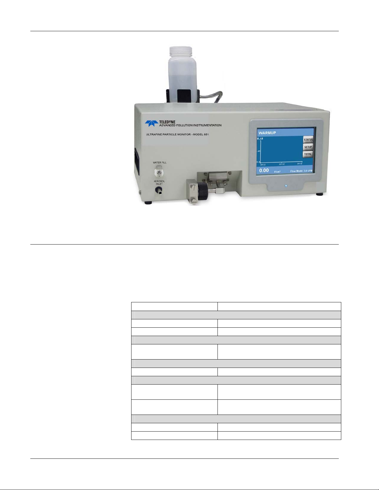
Product Overview Teledyne API Ultrafine Particle Monitor - Model 651
Figure 1-1
Ultrafine Particle Monitor - Model 651
Specifications
Table 1-1 contains the operating specifications for the Model 651
instrument. These specifications are subject to change without
notice.
Table 1-1 Model 651 Specifications
PARAMETER SPECIFICATION
Particle Size Range
Min detectable particle (D50) 7 nm (verified with DMA-classified sucrose)
Max detectable particle 3 μm
Particle Concentration Range
Single Particle Counting
Particle Concentration Accuracy
Measurement Accuracy ±10% at 106 particles/cm3
Response Time (T95)
High flow mode(3 L/min)
Low flow mode (0.6 L/min)
Flow
High-flow inlet 3 ±0.3 L/min
Low-flow inlet 0.6 ± 0.06 L/min
6
0 to 10
coincidence correction
<3 sec to 95% in response to concentration step
change
<5 sec to 95% in response to concentration step
change
particles/cm
3,
with continuous live-time
18 07506C DCN6727
Page 21
Teledyne API Ultrafine Particle Monitor - Model 651 Product Overview
PARAMETER SPECIFICATION
Aerosol flow rate 120 ±12 cm3/min
False Background Counts
False background counts <0.01 particles/ cm3, one hour average
Aerosol Medium
Aerosol medium Air only
Environmental Operating Conditions
Ambient temp range 10 to 38°C (50 to 100.4°F)
Ambient humidity range 0 to 90% non-condensing
Inlet Pressure Operation
Inlet pressure operation
(absolute)
Inlet pressure gauge 1 to -5 kPa (-20 inch H20)
Water System
Condensing liquid Distilled water
Water system
Water consumption ~250 ml/week
Vacuum
Vacuum
Communications
Protocol ASCII command set
Interfaces
RS-232 9-pin, D-Sub connector
USB
Ethernet 8-wire RJ-45 jack, 10/100 BASE-T, TCP/IP
Data Logging
Data logging USB Flash drive
Averaging interval
Outputs
Digital display
Analog output
Digital output
Calibration
Calibration Recommended annually
Power
Requirements 100 to 240 VAC, 50/60 HZ, 175 W max
50 to 110 KPa (0.5 to 1.1 atm)
External 1 liter bottle for up to 4 weeks of
operation.
External vacuum pump not included in
instrument accessories
Type B connector, USB 2.0 compatible at
12 MB
Data averaging interval of 1-3600s
1,2,4,5,6,10,12,15,20,30 or 60s
software provides more avg options.
9-inch QVGA color touch screen with graphical
interface. Graph of conc vs. time,
concentration, time and total counts, and
status
BNC connector, 0 to 10V proportional to
concentration, or 0 to 7V in LOG concentration
mode.
Data download using USB, RS-232 serial, or
Ethernet interface
07506C DCN6727 19
Page 22

Product Overview Teledyne API Ultrafine Particle Monitor - Model 651
PARAMETER SPECIFICATION
Physical Features
Front panel Display, sample inlet, LED particle indicator
Back panel
HxDxW 20.3 x 48.3 x 30.5 cm (8 x 19 x 12 inches)
Weight 9.9 Kg (22 lbs)
Power connector, USB, Ethernet, RS-232, BNC
output, fan, water fill connector, pump exhaust
port, fill bottle and bracket
How it Works
The Ultrafine Particle Monitor - Model 651 is designed to measure
the concentration of airborne particles. The Model 651 draws in an
air sample and counts the number of particles in that sample to
provide a particle concentration value that is displayed as the
number of particles detected per cubic centimeter of sampled air.
The Model 651 utilizes a patented
condensation growth technique. Particles which are too small
(nanometer scale) to scatter enough light to be detected by
conventional optics are grown to a larger size by condensing water
on them. In this instrument, an air sample is continuously drawn
through the inlet via an external pump and a portion of the flow is
sent to the exhaust as transport flow. The stream of aerosol
particles is uninterrupted and follows a laminar flow path from the
sample inlet to the optical detector.
The Model 651 particle counting process is as follows:
*
laminar-flow, water-based
The aerosol enters the sample inlet.
In the conditioner, the aerosol sample stream is saturated with
water vapor and then temperature-equilibrated.
The sample passes to a growth tube where the wetted walls
(composed of a porous medium) are heated to raise the vapor
pressure. The high diffusivity of the water vapor allows the
vapor to reach the center of the sample stream at a faster rate
than the thermal diffusivity of the vapor can equilibrate to the
higher temperatures near the walls—creating a supersaturated
condition along the radius of the flow stream. These unstable
conditions facilitate water condensation on the sample particles.
Particles that are larger than the detection limit of the Model
651’s minimum critical particle size act as condensation nuclei
as they pass up the growth tube.
*
US Patent No. 6,712,881, Aerosol Dynamics Inc., Drs. Susanne V. Hering and Mark Stolzenburg.
20 07506C DCN6727
Page 23

Teledyne API Ultrafine Particle Monitor - Model 651 Product Overview
The enlarged particles are passed through a laser beam and
create a large light pulse. Every particle pulse event is detected
and counted. In this technique, particle concentration is
measured by counting each particle in the air stream.
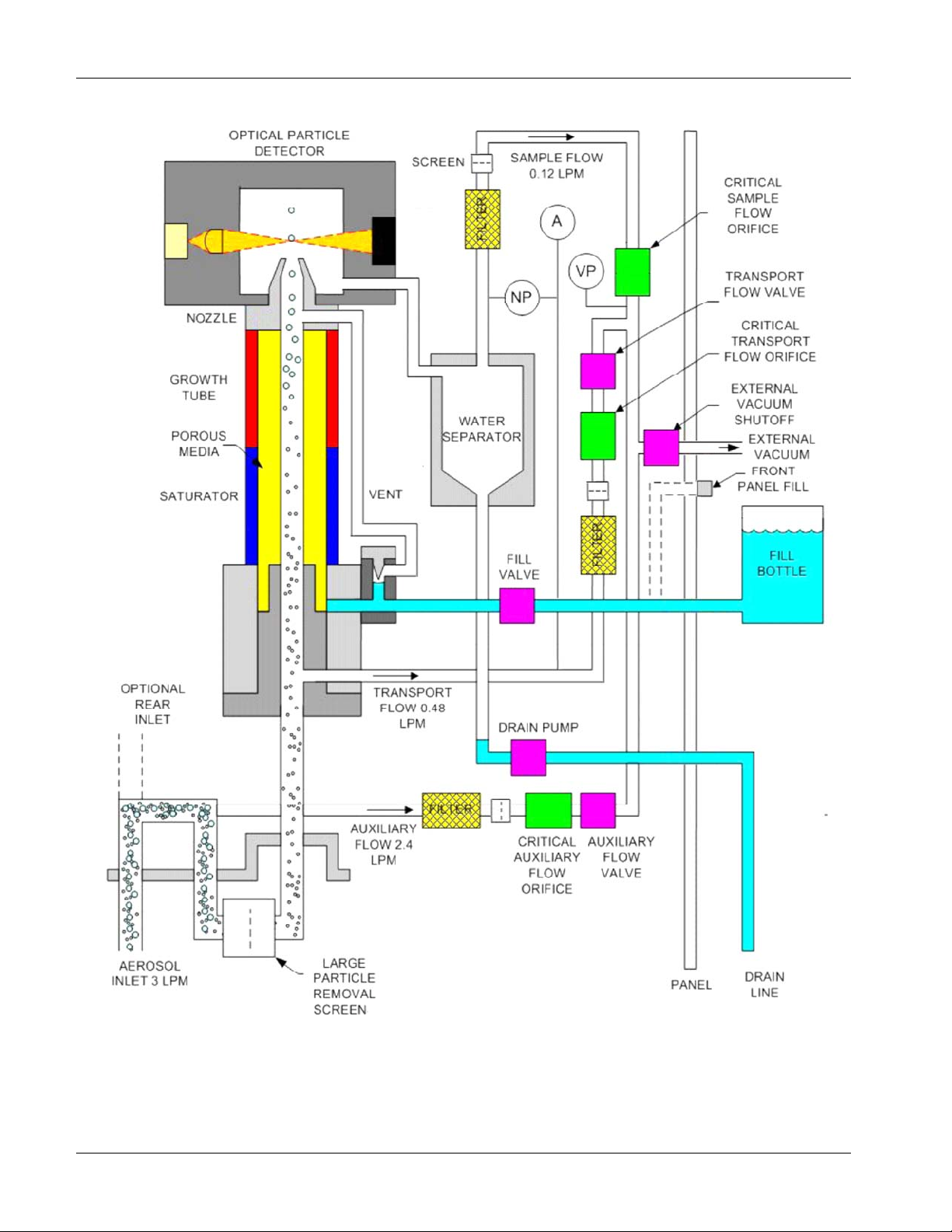
Figure 1-2 illustrates the flow system of the Model 651.
07506C DCN6727 21
Page 24
Product Overview Teledyne API Ultrafine Particle Monitor - Model 651
Figure 1-2
Model 651 Flow System Schematic
22 07506C DCN6727
Page 25

Packing List
CHAPTER 2
Unpacking and Setting
Up the Model 651
Use the information in this chapter to unpack and set up the
Ultrafine Particle Monitor - Model 651.
The packing list described in Table 2-1 shows the components
shipped with the Model 651.
Table 2-2 shows the components included in the Model 651
Maintenance Kit.
Table 2-1 Model 651 Packing List
Part Number/
Qty.
1 081000000 Ultrafine Particle Monitor - Model 651
1 076220000 TAPI Manuals on CD-ROM(KB)
1 075070000 Model 651 Quick Start Guide
1 WR0000008 Power cable, 10A
1 DU0000167 Water supply bottle
1 DU0000168 Water drain bottle
1 DU0000177 Vacuum pump tubing
1 WR0000257 Cable, USB, com
1 WR0000101 RS-232 Serial cable, DB9 M/F
1 DU0000169 Maintenance Kit (for details see Table 2-2 below)
1 KIT000400 Inlet Mounting Kit
Model Number Description
DU0000175 Vacuum pump, 115V, 60Hz
Note: Some items above and those for future maintenance are
available for purchase as kits from TAPI. A complete list of
replacement parts is included in the Maintenance section in
Chapter 9
07506C DCN6727 23
.
Page 26
Unpacking and Setting Up the Model 651 Teledyne API Ultrafine Particle Monitor - Model 651
Table 2-2 Model 651 Maintenance Kit PN DU0000169
Qty. Part Number Description
1 DU0000150 Static Dissipative Sample Inlet Tubing (3M)
3 DU0000234 Filter Replacements M651
1 DU0000161 Replacement Critical Flow Control Orifice .005 inch
1 DU0000162
1 DU0000163
1 DU0000157 3783 Wick Cartridge
12 DU0000158 Wick 3783: Replacement Wicks
1 DU0000178 Three-foot length of 1/8 inch tubing
Replacement Critical Transport Flow Control Orifice
.0095 inch
Replacement Critical Auxiliary Flow Control Orifice
.0225 inch
Unpacking
Carefully unpack the Model 651 from the shipping container (refer
to Chapter 10
Check to ensure there is no damage to the instrument. If any
damage is found, contact the carrier. Use the Packing List in Table
2
-1 to verify that there are no missing components.
to avoid damage due to Electro-Static Discharge).
Save the original shipping container to be used for future shipping.
If anything is missing, TAPI Technical Support by phone or by email:
Phone: 1-800-324-5190 (within the US)
001-858-657-9800 (outside the US)
858-657-9800 (local)
E-mail: sda_techsupport@teledyne.com.
See Chapter 9
to TAPI, and Chapter 3
for instructions on how to return the instrument
for moving/shipping procedures.
Caution – Prevent Damage and Avoid Warranty Invalidation
The Ultrafine Particle Monitor - Model 651 operates using distilled
(<6 ppm) or HPLC water as a working fluid. Do not tip the instrument
more than 10 degrees during normal operation. Perform the procedures
described in Chapter 3
Do not:
Ship an “undried” instrument.
Transport an “undried” instrument over long distances.
Subject an “undried” instrument to freezing temperatures.
Any of the above actions can result in the flooding of the optical system,
performance degradation, and possible damage to the instrument. Such
neglect is not covered under the manufacturer’s warranty.
before moving or shipping the instrument.
24 07506C DCN6727
Page 27
Teledyne API Ultrafine Particle Monitor - Model 651 Unpacking and Setting Up the Model 651
Installation
IMPORTANT
The wick used in the M651 must be changed every 4 weeks (800
hours), and distilled (<6 ppm) or HPLC water must be used as the water
source. Follow the instructions in Chapter 9
This section contains instructions for installing the Model 651
instrument. Follow the instructions in the order given.
The installation procedures, described on the following pages,
include the following:
Removing protective caps.
Connecting the water supply.
Connecting the water exhaust tube.
Connecting the aerosol supply and vacuum line.
Installing the Model 651 in a rack (if desired).
Connecting the USB cable.
Connecting the power and warming up the Model 651.
for wick replacement.
Equipment
You will need the following equipment to install the Model 651:
9/16 inch wrench.
7/64 inch hex driver.
¼-inch, thick-walled, plastic tubing.
Water supply.
Note: Use either distilled (<6 ppm) or HPLC water. Do not use
tap water.
Remove Protective Caps
After unpacking the Model 651, remove the protective caps from the
AEROSOL INLETs on the front and back panels of the instrument
and from the PUMP EXHAUST. Then remove the covers from the
BNC
connectors.
Connecting the Water Supply
The Model 651 uses a gravity-fed water fill system.
Note: To prevent the water from draining back into the bottle during
operation, the bottle must always be placed at a higher level
than the instrument.
07506C DCN6727 25
Page 28
Unpacking and Setting Up the Model 651 Teledyne API Ultrafine Particle Monitor - Model 651
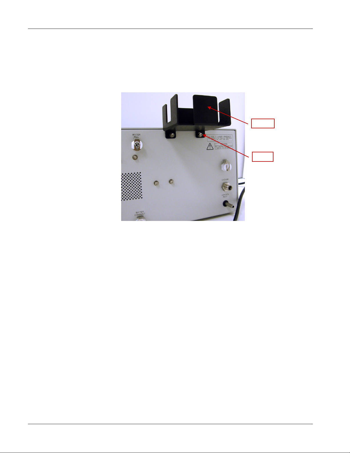
To connect the water supply, follow these instructions:
1. Using a 7/64 inch hex driver, mount the water supply bottle
bracket to the front or back of the particle counter using the
provided bottle bracket mounting screws. The figure below
shows the bracket mounted on the back.
Bracket
Screw
Figure 2-1
Connecting the Water Supply
2. Fill the water supply bottle with either distilled (<6 ppm) or
HPLC water and place the bottle in the bracket.
Note: A filled water supply bottle will typically allow the Model
651 to operate for more than the 4-weeks wick
replacement interval. If water is added between the wick
change, it is recommended that the water be added to the
bottle without disconnecting it from the Model 651 to avoid
adding any bubbles into the water supply line.
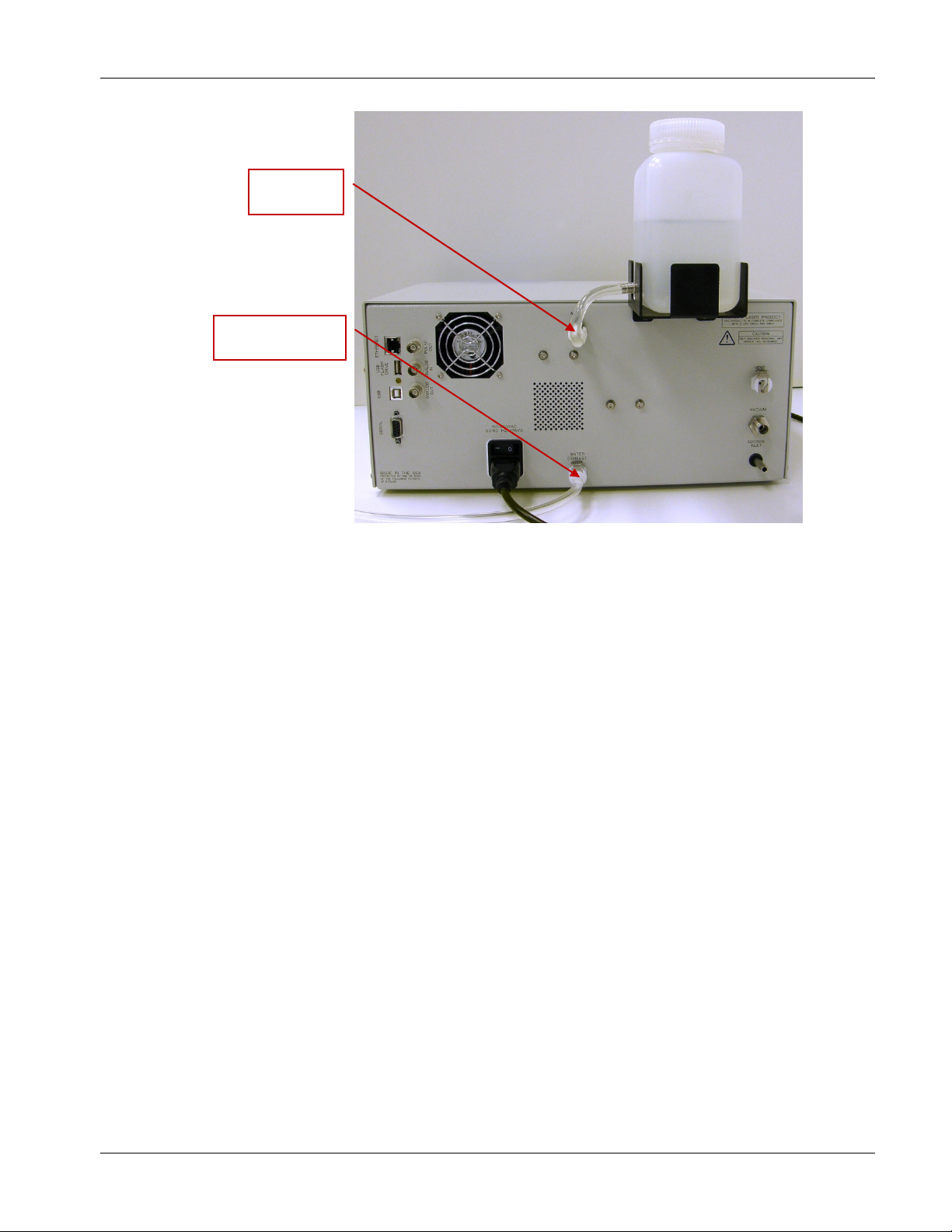
3. Push the connector on the water supply bottle tubing into the
WATER FILL fitting on either the front or back of the
instrument (figure below shows the back).
26 07506C DCN6727
Page 29
Teledyne API Ultrafine Particle Monitor - Model 651 Unpacking and Setting Up the Model 651
WATER FILL
Fitting
WATER EXHAUST
Fitting
Figure 2-2
Water Fill and Water Exhaust Fittings
Connecting the Water Exhaust Tube
The waste water should pass into a suitable drain such as a floor
drain or a vented container. To connect the drain tube:
1. Push the connector on the supplied length of drain tubing into
the WATER EXHAUST fitting on the back panel.
2. Place the other end of the drain tube in a vented container or
over a floor drain.
Connecting the Aerosol Supply
The Model 651 allows you to conduct aerosol sampling from either
the front or the back of the instrument. To run the instrument
effectively, you need an external vacuum capable of drawing
6 SLPM at 400 mbar absolute pressure.
Sampling options include the following:
Ambient sampling using the inlet screen assembly (provided
with the monitor) connected to the Model 651 inlet. The inlet
screen assembly prevents large matter (such as insects and dirt)
from entering the instrument.
Note: If you are sampling from the back of the instrument, you
must use the inlet screen assembly and the flow rate must
be 3 L/min when using the inlet screen.
07506C DCN6727 27
Page 30
Unpacking and Setting Up the Model 651 Teledyne API Ultrafine Particle Monitor - Model 651
Using a sampling system connected directly to the aerosol inlet.
Environmental monitoring using tubing connected directly to
the aerosol inlet.
IMPORTANT
The gauge pressure of the sampled aerosol must be within +4/-20 in.
H
O pressure relative to the ambient pressure. Pressures outside of this
2
range will result in water-handling failures.
To set up the aerosol supply, follow these instructions:
1. Decide whether you will sample from the front or the back of
the instrument.
2. Place the aerosol sample inlet cap over the sample port that you
will not be using.
3. Determine your sampling method. The instrument is shipped
with the inlet screen assembly in place, but if it has been
removed and you wish to use it, you must reconnect it to the
Model 651 inlet. If you are not using the inlet screen, connect
the aerosol sample line to the aerosol inlet.
Figure 2-3
Connecting the Aerosol Supply
4. If you are using the inlet screen assembly and it needs to be
connected, line up the two captive screws with the
corresponding holes on the front panel. The elbow tube should
line up with the nozzle.
28 07506C DCN6727
Page 31

Teledyne API Ultrafine Particle Monitor - Model 651 Unpacking and Setting Up the Model 651
w
Elbow Tube
Inlet Screen Assembly
Captive Scre
Figure 2-4
Connecting the Aerosol Supply to Inlet Screen Assembly
5. Turn the captive screws to secure the inlet screen assembly in
place. Tighten with hex key (supplied with the instrument).
Nozzle
Figure 2-5
Securing Inlet Screen Assembly in Place
6. If you have not already done so, remove the protective cap from
the VACUUM inlet on the back panel.
07506C DCN6727 29
Page 32

Unpacking and Setting Up the Model 651 Teledyne API Ultrafine Particle Monitor - Model 651
7. Connect an external vacuum source to the VACUUM inlet using
the vacuum tubing provided with the instrument, and a 9/16inch wrench to tighten the Swagelok
®
fitting.
Vacuum Inlet
Figure 2-6
Connecting External Vacuum Source
Installing the Model 651 in a Rack
Before you can install the Model 651 instrument in a rack, you
must attach the rack-mount brackets. To attach the rack-mount
brackets, follow these instructions:
1. Using a 1/8-inch hex driver and the mounting screws provided
with the particle monitor, attach the rack-mount brackets to the
front sides of the instrument.
Note The bracket with the USB port should be attached to the
front right of the instrument.
Swagelok is a registered trademark of Swagelok Company.
30 07506C DCN6727
Page 33

Teledyne API Ultrafine Particle Monitor - Model 651 Unpacking and Setting Up the Model 651
Figure 2-7
Installing Model 651 in a Rack
2. Place the Model 651 in the rack.
WARNING
When mounting the instrument in a rack location be certain that the
back panel power on/off switch is accessible or that a readily accessible
means of disconnecting power is provided.
Connecting the USB Cable
Connect the provided USB cable to the USB connector on the back
panel of the Model 651. If you have placed the monitor in a rack,
you can use an extension cord to connect the port at the back of
the instrument to the port on the rack-mount handle to give you
easy access to the USB port.
Connecting Power and Warming up the Model 651
After you connect the power, the warm-up process takes
approximately 20 minutes.
Follow these instructions to connect the power and warm up the
Model 651:
1. Plug the power cord provided with the Model 651 into the power
connector (100 to 240 VAC 50/60 Hz 175 W) on the back panel.
2. Plug the cord into an earth-grounded AC power source (100 to
240 VAC, 50 to 60 Hz, 175 W).
07506C DCN6727 31
Page 34

Unpacking and Setting Up the Model 651 Teledyne API Ultrafine Particle Monitor - Model 651
WARNING
Connection to an improperly grounded electrical source may cause a
severe shock hazard—ensure that the ground is secure.
3. Turn on the instrument. The Home screen appears on the
display and reads Warmup. During the warm-up process, status
messages are displayed at the top left of the home screen.
Figure 2-8
Warm-up Screen
4. When the warm-up is complete, if all conditions for operation
are in place, the display reads Ready. If you do not see the
Ready message, check the settings.
32 07506C DCN6727
Page 35

CHAPTER 3
Moving and Shipping
the Model 651
Use the information in this chapter to prepare the Ultrafine Particle
Monitor - Model 651 for moving or shipping.
Caution- Prevent Damage and Avoid Invalidating the Warranty.
The Model 651 operates using water as a working fluid. Do not tip the
instrument more than 10 degrees during normal operation or you may
flood the optical system.
Do not:
Ship an “undried” instrument.
Transport an “undried” instrument over long distances.
Subject an “undried” instrument to freezing temperatures.
Any of the above actions can result in the flooding of the optical system,
performance degradation, and possible damage to the instrument. Such
neglect is not covered under the manufacturer’s warranty.
Moving the Model 651 Short Distances
You can successfully transport the Model 651 short distances from
one lab to another, or even a short drive in a vehicle, without
draining it first. However, do not tip the instrument >45°and do not
subject it to prolonged freezing temperatures.
Preparing the Model 651 for Shipping and Storage
To prepare the Model 651 for shipping, follow these instructions:
1. Disconnect the water bottle, empty it, and then reconnect it.
2. If you have not already done so, turn on the particle monitor
and allow it to warm up (the display screen reads Ready when
the warm-up is complete and all the settings are correct).
3. Disconnect any connections to the aerosol inlet.
4. Allow the instrument to operate for at least one hour with the
water source disconnected.
5. Disconnect the drain tube from the WATER EXHAUST outlet.
6. Turn off the power.
07506C DCN6727 33
Page 36

Moving and Shipping the Model 651 Teledyne API Ultrafine Particle Monitor - Model 651
7. With the inlet screen assembly securely in place, carefully place
the instrument in the original packing materials. (Detailed
instructions for attaching the inlet screen assembly are given in
Chapter 2, “Connecting the Aerosol Supply
”.)
The Model 651 is now ready for shipping or storage.
34 07506C DCN6727
Page 37

Front Panel
y
y
Rack-Mount
Bracket
CHAPTER 4
Instrument Description
Use the information in this chapter to become familiar with the
location and function of controls, indicators, and connectors on the
Ultrafine Particle Monitor - Model 651.
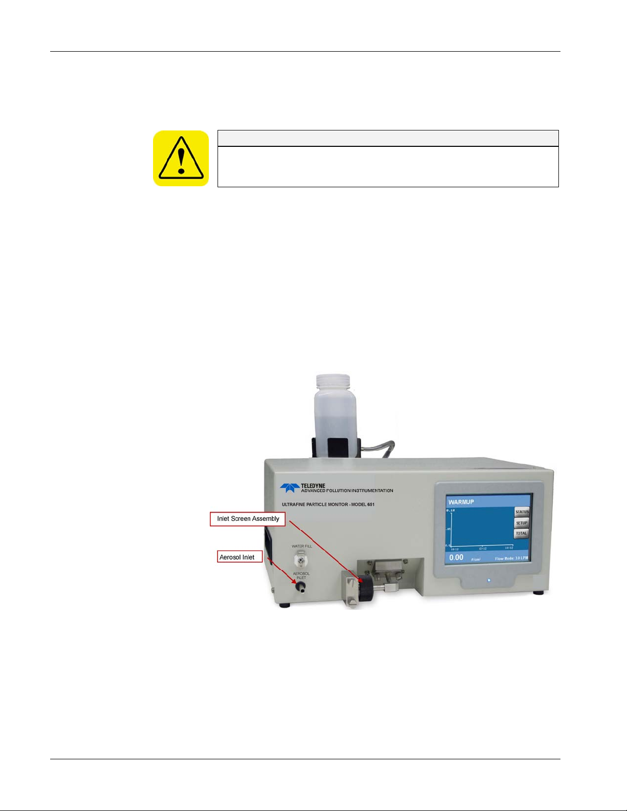
The main components of the front panel are shown in the
figure below.
Displa
Water Fill
Aerosol inlet
Figure 4-1
Inlet Screen Assembl
Model 651 Front Panel
Indicator Light
Display
The QVGA color LCD display provides continuous, real-time display
of sample data as well as user menus and status information.
Pressing the display “buttons” allows you to move from one screen
to another or to record settings.
07506C DCN6727 35
Page 38

Instrument Description Teledyne API Ultrafine Particle Monitor - Model 651
Status Messages
Status messages display at the top of the home screen. The
indicators are as follows:
Status Indicator Description
Low Water Water level is low
Warmup Instrument is warming up
Laser Fault Laser fault
Inlet Pressure Fault Inlet pressure is too high/low
Vacuum Fault Vacuum pressure is too high/low
Nozzle Fault Plugged nozzle or wet sample flow filter
Absolute Pressure Fault Barometric pressure is out of range
Optics Temp Fault Optics temperature is out of range
Growth Tube Temp Fault Growth Tube temperature is out of range
Conditioner Temp Fault Conditioner temperature is out of range
Separator Temp Fault Water Separator temperature is out of range
Pulse Height Fault Low particle pulse height
Ready Warm-up process has finished and the
instrument is ready for use
Note: The status messages on the front-panel display either indicate
that the instrument is warming up or that there is a problem
with the instrument. However, only one indicator can display
at a time. Check the Status screen for more details about
potential problems.
Indicator Light
The blue indicator light on the front panel flashes once for each
particle detected. At particle concentrations >100 particles/cm
flashing becomes a continuous glow.
3
, the
36 07506C DCN6727
Page 39

Teledyne API Ultrafine Particle Monitor - Model 651 Instrument Description
Back Panel
The main components of the back panel are shown in the figure
below. Components include power and data connections, analog
input/output connections, and water and sample inlets/outlets.
Water Fill
Water Bottle Bracket
Water Supply Air Vent
Data
Communication
Ports
Power Supply
Water Drain
Figure 4-2
Model 651 Back Panel
Vacuum Inlet
Aerosol Inlet
07506C DCN6727 37
Page 40

Instrument Description Teledyne API Ultrafine Particle Monitor - Model 651
Internal Instrument Components
Internal components are described in this section and identified in
the photos below.
Filters (x3)
Figure 4-3
Model 651 Internal Components (viewed from instrument front)
Optics Module
The optics module detects particle droplets from the growth tube.
The optics module contains a laser, photodetector, and the optics,
as well as the detector and optics circuit boards.
Vacuum Supply
An external vacuum supply enables all the flows. The internal
vacuum control valve (controlled by parameters available on the
38 07506C DCN6727
Page 41

Teledyne API Ultrafine Particle Monitor - Model 651 Instrument Description
SETUP screen) is an electronic valve used to turn on/off the
vacuum from the external source.
Water System
The water separator removes water from the vapor stream coming
from the optics head. This prevents water from condensing and
blocking the flow orifices. Water from the separator is pumped out
by the water ejector pump.
The instrument flow orifices operate under critical pressure with
flow determined by the orifice diameter. Each orifice is protected by
a glass fiber filter followed by a separate inline screen to remove
contamination which can result from an accidental flooding event.
Fans
Two internal fans cool the instrument; one cools the internal
electronics and one dissipates the heat generated during cooling of
the condenser.
Circuit Boards
The Model 651 contains the following circuit boards:
Main board
Laser board
Detector board
The main circuit board controls all the primary functions. Feedback
circuits on the main electronics board control the internal
temperatures (displayed on the Status screen).
Internal Clock
The clock used in the Model 651 is a quartz crystal component
embedded in the microprocessor. The accuracy is on the order of
about a second per day, but time drift during long periods of data
logging is possible. If a higher level of time accuracy is needed, one
of the following options should be implemented:
1. Send a serial command to the instrument once per day to reset
the M651 clock to synchronize with the data collection tool.
2. If collecting data via the USB stick, reset the clock on the
instrument as needed.
07506C DCN6727 39
Page 42

Instrument Description Teledyne API Ultrafine Particle Monitor - Model 651
Data Communication Ports
USB Communication Port
The Model 651 provides a USB port for communications use.
RS-232 Serial Connections
The Model 651 provides one standard, 9-pin RS-232 serial port that
allows communication between a computer and the particle
monitor. Serial commands are sent to and from the computer to
monitor instrument status information, to retrieve and monitor
data, and to provide a variety of control functions such as turning
the pump on and off. More information can be found in the
Computer Interface
Analog Input
The Model 651 can monitor the analog voltage from an external
source via the analog input BNC connector on the back panel
(labeled Analog Input). The input voltage range for these ports is
0 to 10 V. Analog voltages can be displayed together with
concentration data on the display screen and can be saved to the
removable Flash Drive or a computer. Voltages from connected
pressure, flow, or temperature transducers can be correlated to
particle concentration in real time.
Amplification must be supplied by the user to bring low voltage
signals to the appropriate 0 to 10 V range for best resolution.
section of Chapter 8 in this manual.
DMA/Analog Out and Pulse Out
During normal operation of the Model 651, the Analog Out port
provides an analog 0 to 10 V signal proportional (linear or log) to
particle concentration. This particle concentration is corrected for
coincidence and tracks the displayed concentration.
Pulse Out provides a 5-volt (50-ohm termination) digital pulse for
each particle detected. This enables you to use your own counting
electronics hardware and provides a particle trigger for special
applications. The width of the pulse depends on both the shape of
the photo detector pulse and the trigger-level of the pulse threshold.
To provide accurate pulse counts, use a counter that is capable of
counting pulses with a width of 50 nanoseconds or less.
Particle concentrations that have been calculated based on the
particle counts from the counting electronics hardware are not live-
time corrected for particle coincidence. Thus, when particle
concentration is high, the concentration provided by this output
might be lower than the displayed concentration. Appropriate
coincidence correction should be applied when pulse output is used
for high concentration measurements.
40 07506C DCN6727
Page 43

Teledyne API Ultrafine Particle Monitor - Model 651 Instrument Description
The pulse output is a way to get raw particle count information.
This information is also available through serial command. Using
the SM or SSTART,3 command, described in Appendix B
read raw, uncorrected, particle counts. TAPI recommends using the
serial interfaces for raw counts rather than the pulse output
because then all the information used to calculate the corrected
concentration is communicated and there are no issues with the
monitor’s ability to accurately count the pulses.
, you can
Ethernet Communication Port
Instrument status, including particle concentration, of the Model
651 can be monitored remotely from a local area network or over
the internet using the Ethernet communication port.
07506C DCN6727 41
Page 44

Instrument Description Teledyne API Ultrafine Particle Monitor - Model 651
This page intentionally left blank.
42 07506C DCN6727
Page 45

CHAPTER 5
Instrument Operation
This chapter describes the basic operation of the Ultrafine Particle
Monitor - Model 651 and describes how to use the controls,
indicators, and connectors found on the front and back panels.
Operating Precautions
Read the following before applying power to the particle monitor:
Review the operating specifications for the Model 651 described
in Appendix A
Do not operate the Model 651 at temperatures outside the
range of 10C to 35C. If the particle monitor is operated outside
this range, the displayed concentration may be inaccurate.
The Model 651 should not be used with hazardous gases such as
hydrogen or oxygen. Using the particle monitor with hazardous gases
may cause injury to personnel and damage to equipment.
.
WARNING
Recommended Operation Procedures
Outdoor Operation Procedures
When sampling outdoor aerosol, follow these recommendations:
Place the Model 651 in a conditioned enclosure or shelter to
ensure that it is operating within temperature and humidity
specifications.
If the Model 651 is placed in an environment with temperatures
lower than the ambient temperature, consider heating the
sample line to reduce condensation.
If you are not using a sampling system, use a cyclone with a cut
size no greater than 3 µm on the particle counter inlet.
Ensure that the pressure differential at the inlet is not greater
than 2.5 kPa (10 inches of H
not exceed the inlet pressure drop of 2.5 kPa.
07506C DCN6727 43
O). If you are using a cyclone, do
2
Page 46

Instrument Operation Teledyne API Ultrafine Particle Monitor - Model 651
Follow the startup advice contained in the Quick Start Guide
(shipped with the instrument).
Standard Operation Procedures
Perform these standard procedures every 4 weeks (800 hours):
Replace the wick.
Check the flow using a volumetric flowmeter.
Fill the water bottle with 1 liter of distilled (<6 ppm) or HPLC
water. Do not use tap water.
Verify that the inlet pressure is in the correct operating range
relative to the ambient pressure:
o Check the inlet pressure value on the status screen, then
disconnect the aerosol inlet and check the value again. The
pressure drop caused by an inlet restriction should not
exceed 250 mbars (25 kPa).
or
o Check inlet pressure on the status screen, then turn the
instrument vacuum off and check the pressure again. The
pressure drop caused by an inlet restriction should not
exceed 250 mbars (25 kPa).
Check the status screen to make sure the parameters are still
accurate.
Check the inlet screen and remove any debris collected there.
Check the time and date on the Flash Drive.
Perform these standard procedures annually:
Replace the filters.
Perform a Zero check by placing a HEPA filter on the Model 651
inlet and ensuring that particle concentration is
<0.01 particles/cm
3
.
Note: Detailed information about these procedures can be found in
the Maintenance section of Chapter 9
44 07506C DCN6727
.
Page 47

Teledyne API Ultrafine Particle Monitor - Model 651 Instrument Operation
Warm-up
When you have successfully made all the connections described in
the Installation section of Chapter 2
Home screen appears on the display and reads Warmup. When the
warm-up process is complete, and the optics and growth tube
temperatures are within two degrees of their standard operating
temperatures, the display reads Ready. You can then use the menus
to do the following:
Turn flow on and off.
Set the date and time.
Set sampling parameters.
Check flow.
Collect data.
Set the network and data collection options.
, and turned on the power, the
Display/User Settings
Read this section for details of the screens, how to make selections,
and how to change options.
HOME Screen
The Home screen displays a real-time sample graph of the
concentration in particles/cm
the SETUP and TOTAL options. You can return to the Home screen
from any other screen by pressing HOME.
The following screens are accessible from the home screen and are
described on the following pages:
STATUS
SETUP
TOTAL
STATUS Screens
The two STATUS screens display a variety of real-time readings to
give you an instant view of the operational status of the instrument.
The following status colors are significant:
Red indicates a parameter that is “out of range.”
Yellow indicates something “in process.”
White indicates “normal” conditions.
3
, the STATUS of the instrument, and
07506C DCN6727 45
Page 48

Instrument Operation Teledyne API Ultrafine Particle Monitor - Model 651
Press MORE on the first Status screen to see the ADDITIONAL
STATUS settings. The photos below show the STATUS and
ADDITIONAL STATUS screens.
The Status screens display the following information:
Status Description
Concentration
Pulse Height
Represented in particles/cm
The signal height in mV. The pulse height varies
3
with particle concentration and is useful for
indicating problems with the wick.
Optics Temp
Temperature of the Optics in degrees Celsius. A
normal Optics temperature is 60°C.
Growth Tube Temp
Temperature of the Growth Tube in degrees
Celsius. A normal Growth Tube temperature is
60°C.
Conditioner Temp
Temperature of the Conditioner in degrees Celsius.
A normal Conditioner temperature is 20°C.
Vacuum
The vacuum pressure in mbars (must be less than
half of the inlet pressure).
Inlet Pressure
The atmospheric pressure in mbars. This
parameter is preset and can be used to indicate a
blockage.
46 07506C DCN6727
Page 49

Teledyne API Ultrafine Particle Monitor - Model 651 Instrument Operation
Status Description
Nozzle Pressure
Separator Temp
Cabinet Temp
Laser Current
Photodetector
Analog Input
Flow Constant
The pressure difference upstream and downstream
of the optics assembly. Should be 100% - a 10%
drop in nozzle pressure indicates a nozzle clog.
Temperature of the Separator in degrees Celsius. A
normal Separator temperature is 7°C.
Temperature inside the Model 651 cabinet.
The operating current of the laser in mA.
Indicates photodetector voltage in mV.
Displays the voltage of the analog input.
Represented in particles/cm
variations in orifice diameter.
3
. Compensates for any
SETUP Screens
HOME | SETUP
Pressing the SETUP button on the home screen takes you to the
SETUP screen where you can set the following operating
parameters:
Parameter Description
SAMPLE TIME
VACUUM
INLET FLOW
SET TIME
MORE
NETWORK SET
UP
MORE
ADDITIONAL
SETUP
ANALOG
OUTPUT
LOGGING
Select a sample time for updating the display
graph. Choices are 1 sec, 2 sec, 3 sec, 4 sec, 5
sec, 6 sec, 10 sec, 12 sec, 15 sec, 20 sec, 30
sec, 60 sec.
Turn the vacuum valve on/off.
Set the inlet flow. Choices are 3 L/min (total flow),
0.12 L/min (sample flow), and
0.6 L/min (transport flow).
Set the time for the internal, real-time clock used
for data logging purposes.
Takes you to the NETWORK SETUP screen.
Set up network connections including
NETWORK, ADDRESS, MASK, and GATEWAY.
Takes you to the ADDITIONAL SETUP screen.
Specify the ANALOG OUTPUT and LOGGING
time.
Set an analog voltage range for the output.
Choose intervals for logging data.
07506C DCN6727 47
Page 50

Instrument Operation Teledyne API Ultrafine Particle Monitor - Model 651
The following pages contain descriptions of the SETUP options.
SAMPLE TIME
SETUP | SAMPLE TIME
Select a sample time in seconds for the on-screen graph. Press the
SAMPLE TIME button to scroll through the settings. Sample Time
choices are 1, 2, 3, 4, 5, 6, 10, 12, 15, 20, 30, and 60 seconds. If
you intend to gather data for long periods of time, use the longer
sample times to reduce the number of data files.
VACUUM
SETUP | VACUUM
Select one of the following vacuum settings:
Vacuum Setting Description
ON AFTER
WARMUP
ON
OFF
Note: You can toggle between the ON and OFF settings.
Turns on the vacuum. Message displays during
the warm-up process.
Turns on the vacuum valve. Message only
displays when warm-up is complete.
Turns off the vacuum valve.
INLET MODE
SETUP | INLET MODE
Set the inlet flow in liters per minute. Press the INLET MODE
button to scroll through the settings. Inlet flow choices are:
Inlet Mode Setting Description
3 L/min
0.12 L/min
This setting will pull the total flow through the inlet:
including sample flow (0.12 lpm), transport flow
(0.48 lpm), and auxiliary flow (2.4 lpm), This is
flow during normal operation.
This setting will include sample flow (0.12 lpm)
only through the inlet, transport and auxiliary flows
are off.
0.6 L/min
48 07506C DCN6727
This setting will include only the transport (0.48
lpm) and the sample flow (0.12 lpm) through the
inlet and the auxiliary flow is off.
Page 51

Teledyne API Ultrafine Particle Monitor - Model 651 Instrument Operation
SET TIME
SETUP | SET TIME
Allows you to select the date (year, month, and day) and time (hour,
minute, and second) for data collection.
To set the date and time, follow these instructions:
1. Touch the screen option you wish to change. In the photo
below, the Year is active (indicated by the line below the
number) and ready to be changed.
2. Use the
3. Touch BACK to return to the previous screen when you have
made your choices.
arrows to scroll through the different settings.
NETWORK
SETUP | NETWORK SETUP | NETWORK
Allows you to specify the network settings. The NETWORK button
toggles between the settings STATIC and DHCP (shown below).
Note: If the network settings have been selected, they are displayed,
otherwise they are blank.
07506C DCN6727 49
Page 52

Instrument Operation Teledyne API Ultrafine Particle Monitor - Model 651
On this screen, only the network setting has been specified.
On this screen all network settings have been specified.
ADDRESS
SETUP | NETWORK SETUP | ADDRESS
Allows you to specify an IP address for your network. To set the IP
Address, follow these instructions:
1. Press the numbers on the on-screen keypad.
2. When you have selected all the numbers, press ENTER. The IP
Address is now recorded and displayed on the screen.
3. Press BACK to return to the Network setup screen where the IP
address is now displayed.
50 07506C DCN6727
Page 53

Teledyne API Ultrafine Particle Monitor - Model 651 Instrument Operation
MASK
SETUP | NETWORK SETUP | MASK
Allows you to specify the network mask.
Note: The Mask must match the size of your network. A typical
setting is 255.255.255.0 for a small network.
To set the Mask, follow the instructions for using the onscreen
keypad to set the IP Address.
GATEWAY
SETUP | NETWORK SETUP | GATEWAY
Allows you to specify the network gateway device. To specify the
Gateway, follow the instructions for using the onscreen keypad to
set the IP Address.
ANALOG OUTPUT
SETUP | NETWORK SETUP | MORE | ADDITIONAL SETUP |
ANALOG OUTPUT
Allows you to set the function of the analog output. Press the
button to scroll through the options. Settings are 1.00, 100, 1000,
4,
1.0 E
output) and STATUS OUTPUT (where a normal Status Output is 0.
Abnormal output is 5V).
1.0 E5, 1.0 E6, 1.0 E7#/cm3 FS, LOG OUTPUT (Logarithmic
LOGGING
SETUP | NETWORK SETUP | MORE | ADDITIONAL SETUP | LOGGING
Allows you to choose intervals for logging data to the Flash Memory
Card. Logging options are either one hour, or one day. Press the
button to toggle between the options.
TOTAL Screen
Pressing the TOTAL button on the home screen takes you to the
TOTALIZER screen. The screen displays the following information:
Current particle concentration in #/cm
Number of accumulated particles.
Sample time in seconds.
Volume based on flow rate and sample time.
This option is useful for manually measuring concentration over a
period of time.
There is a toggle button at the bottom of the screen. When you
choose TOTAL from the Home screen, the toggle button displays
CLEAR TOTALIZER. When you press CLEAR TOTALIZER, the
button displays START TOTALIZER.
3
.
07506C DCN6727 51
Page 54

Instrument Operation Teledyne API Ultrafine Particle Monitor - Model 651
Note: If you go to another screen on the display, the TOTALIZER
continues to run, it can only be stopped by pressing STOP
TOTALIZER.
52 07506C DCN6727
Page 55

Theory
CHAPTER 6
Technical Description
The Model 651 is a continuous-flow, water-based, condensation
particle counter that detects particles down to <7 nm at a sample
flow rate of 0.12 L/min. This section describes the function of the
particle counter, its subsystems and its components. A discussion
of operation theory is given first.
The Model 651 acts very much like an optical particle counter.
However, the particles are first enlarged by a condensing vapor to
form easily detectable droplets. Portions of the following discussion
(focusing on how to condense the vapor onto the particles) are
taken from a paper by Keady, et al. [1986].
In heterogeneous condensation, the vapor surrounding particles
reaches a certain degree of supersaturation and begins to condense
onto the particles. In homogeneous nucleation (self-nucleation),
supersaturation is so high that condensation can take place even if
no particles are present because molecules of the vapor form
clusters (nucleation sites) due to the natural motion of the gas and
attractive van der Waals forces. The Model 651 operates below the
supersaturation ratio to avoid homogeneous nucleation.
The degree of supersaturation is measured as a saturation ratio
(P/P
), which is defined as the actual vapor partial-pressure divided
s
by the saturation vapor pressure for a given temperature:
P
supersaturation =__
P
s
For a given saturation ratio, the vapor can condense onto particles
only if they are large enough. The minimum particle size capable of
acting as a condensation nucleus is called the Kelvin diameter and
is evaluated from the following relationship:
P (4
saturation ratio =__ = exp
P
07506C DCN6727 53
s
M)
_____
RTd
Page 56

Technical Description Teledyne API Ultrafine Particle Monitor - Model 651
where = surface tension of the condensing fluid
M = molecular weight of the condensing fluid
R = universal gas constant
T = absolute temperature
d = Kelvin diameter
The higher the saturation ratio, the smaller the Kelvin diameter.
The saturation vapor pressure P
For a curved liquid surface, such as the surface of a droplet, the
actual saturation vapor pressure is greater. The smaller the droplet,
the easier it is for the vapor molecules to escape the liquid surface.
The Kelvin diameter defines the critical equilibrium diameter at
which a pure droplet is stable (there is neither condensation nor
evaporation). Liquid particles with diameters smaller than the
critical equilibrium diameter will evaporate and larger particles will
grow even larger by condensation. The larger particle will grow until
the vapor is depleted, causing the saturation ratio to fall until it is
in equilibrium with the particle droplet. The lower size sensitivity of
the counter is determined by the operating saturation ratio.
= density of the condensing fluid
is defined for a flat liquid surface.
s
Design of the Model 651
Submicrometer particles are drawn into the particle counter and
enlarged by condensation of a supersaturated vapor into droplets
that measure several micrometers in diameter. The droplets pass
through a lighted viewing volume where they scatter light. The
scattered-light pulses are collected by a photodetector and
converted into electrical pulses. The electrical pulses are then
counted and their rate (live-time corrected) is a measure of
particle concentration.
The basic instrument consists of three major subsystems: the
sensor, the microprocessor-based signal-processing electronics,
and the flow system. The sensor and the flow system are
described below.
Sensor
The sensor contains a conditioner, a growth tube, and an optical
detector (shown schematically in Figure 1-2). The sensor grows the
sampled aerosol particles into larger droplets that are detected
optically.
54 07506C DCN6727
Page 57

Teledyne API Ultrafine Particle Monitor - Model 651 Technical Description
The sample flow is cooled with a thermoelectric device in the
conditioner. The vapor passes into the growth tube where it
becomes supersaturated and condenses onto the aerosol particles
(acting as condensation nuclei) to form larger droplets. The
droplets pass through a nozzle into the optical detector.
The sensor’s optical detector is comprised of a laser diode,
collimating lens, cylindrical lens, elliptical mirror, and photodiode
detector. The laser and collimating lens form a horizontal ribbon of
laser light above the aerosol exit nozzle. The collection mirror
focuses the light scattered by the droplets at a 90° angle (side
scatter) onto a low-noise photodiode. The main beam is blocked by
a light-stop in the back of the sensing chamber. A reference
photodiode is used to maintain constant laser power output. The
surface temperature of the optics housing is maintained at a higher
level than the growth tube to avoid condensation on the optical
surfaces.
The Model 651 operates in single particle count mode up to 10
particles/cm
3
. Rather than simply counting individual electrical
6
pulses generated by light scattered from individual droplets, the
Model 651 uses a continuous, live-time correction to improve
counting accuracy at high particle concentrations. Live-time
correction occurs when the presence of one particle obscures the
presence of another particle creating an undercounting error that
results in dead time.
Pulse Height
The Model 651 contains an electronic sub-system for monitoring
the amplitude (voltage height) of the particle pulse generated by the
optical detector. The actual amplitude of the pulse does not affect
the particle counting performance as long as it is large enough to
intercept the preset discriminator threshold. Typical pulse
amplitudes (1 to 2 volts) are 10 to 40 times higher than the
discriminator level which is typically 20 times higher than the RMS
noise level of the photo-detector electronics. This large magnitude of
‘signal-to-noise’ margin provides robustness in performance in the
optical detection of droplets.
Under normal operating conditions, the pulse amplitude decreases
with increasing particle concentration. As particle concentration
increases, depletion effects within the growth tube cause the
nucleated droplets to grow to smaller sizes than they would at lower
particle concentrations.
Note: The droplet size has been reduced in this instrument compared
to those of previous generations - reducing the variation in
pulse amplitude with respect to particle concentration to about
2:1 over the concentration range of the instrument.
07506C DCN6727 55
Page 58

Technical Description Teledyne API Ultrafine Particle Monitor - Model 651
Changes in optical alignment, laser power, operating temperatures,
flow rates, presence of water, or optical cleanliness can all reduce
pulse amplitude, therefore the pulse amplitude indicates the
“health” of the WCPC. A peak-sense and hold circuit within the
Model 651 measures the pulse amplitude of 50 particles/sec. The
average pulse amplitude is displayed both numerically and in a bar
graph on the Status screen, and is also included in the data
retrieved from the digital interfaces. The limitation of the Pulse
Height indication is that is requires the presence of at least 50
particle pulses/sec to provide information. The Pulse Height fault
status indication is displayed for particle concentrations over
1000 #/cm
measuring very low concentrations (<10 #/cm
3
with a pulse height of less than 350 mV. When
3
) the Pulse Height
fault may be displayed even though the correct particle
concentration is provided.
Flow System
Refer to Figure 1-2 while reviewing the instrument flow information.
The Model 651 relies on an external vacuum supply to maintain
constant flows through three critical orifices. These independent
flows can be verified by toggling into the different flow modes.
Orifice Description
0.12 L/min aerosol
sample flow mode
3.0 L/min auxiliary
flow mode
Carries the aerosol to be sampled. This is not
user-selectable.
Provides a higher flow rate for use with sampling
systems.
Note: 2.4 L/min auxiliary flow is removed to
leave a transport flow of 0.6 L/min.
0.6 L/min transport
flow mode
Reduces particle losses.
Note: 0.48 L/min transport flow is removed to
leave a sample flow of 0.12 L/min.
The flow rate through the sensor is always 0.12 L/min,
independent of the inlet flow rate setting. Problems with the aerosol
flow can be detected by monitoring the pressure drop across the
nozzle and verifying that the critical orifice pressure is maintained.
Critical Flow
To achieve the 0.12 L/min sample flow through the sensor, an
orifice is used (operated at the critical pressure ratio) to provide a
critical flow. Critical flow is very stable and is a constant volumetric
flow, ensuring accurate concentration measurements despite varied
inlet pressure.
56 07506C DCN6727
Page 59

Teledyne API Ultrafine Particle Monitor - Model 651 Technical Description
The critical pressure ratio is found by dividing the absolute
pressure downstream of the orifice P
upstream of the orifice P
. This ratio must be below 0.528 for air.
U
, by the absolute pressure
D
P
D
P
U
528.0pressure Critical
The following pressure values are displayed on the Status screen
and can affect the Model 651 flow.
Pressure Value Description
Vacuum
Inlet Pressure
Nozzle Pressure
The vacuum pressure
The inlet pressure.
The differential pressure across the sensor flow
orifice
Temperature Control
The temperatures of the conditioner, growth tube, and optics are
nominally maintained at 20°C, 60°C, and 60°C, respectively, with
specified ambient temperatures in the operating range of 10°C to
40°C. Temperatures are controlled through feedback circuits on the
main electronics board and are displayed on the Status screen on
the front-panel display.
Note: For ambient temperatures outside the instrument operating
range, the instrument temperature performance may not be
maintained. Moderate increases in conditioner temperature
will raise D
a small amount.
50
Vacuum Supply
The external vacuum supply must be sufficient to maintain the
sample flow at 0.12 L/min along with the auxiliary and transports
flows. The recommended supply is 4 SLPM at 400 mbar absolute
pressure.
Inlet Pressure Measurement
With an adequate vacuum supply, the Model 651 can operate at
inlet pressures in the range of 75 to 105 kPa. The inlet pressure is
measured by an absolute pressure sensor and is equal to the
barometric pressure if no inlet restriction is present.
07506C DCN6727 57
Page 60

Technical Description Teledyne API Ultrafine Particle Monitor - Model 651
The Inlet Pressure reading is displayed on the Status screen on the
front-panel display.
Water Removal System
The Model 651 has a water separator and ejection system to remove
water from the vapor stream exiting the optics assembly. The water
separator condenses the water vapor and then the collected water is
ejected through the WATER EXHAUST port on the back panel and
away from the internal flow control orifices. A drain tube or bottle is
provided to allow the small amount of expelled water to be directed
away from the instrument to a suitable drain.
Counting Efficiency and Response Time of the Model 651
The Model 651 has a lower detection curve with a D50 of 7 nm. D50
is defined as the particle diameter at which 50% of particles are
detected. The curve fit shown in Figure 6-1 is based on testing of
three Ultrafine Particle monitors using sucrose particles generated
by TSI Model 3480 Electrospray Aerosol Generator and sizeclassified with TSI Model 3080 Electrostatic Classifier and Model
3085 Nano Differential Mobility Analyzer (DMA). The counting
efficiency is calculated by comparing the Model 651 readings to TSI
Model 3068A Aerosol Electrometer readings.
The particle concentration measured by the particle counter is the
total number concentration of all particles that the Model 651 can
detect. This measurement provides no size differentiation and it is
not corrected using the Model 651 counting efficiency curve.
The Model 651 has a fast response time. T
takes for the instrument reading to reach 95% of a concentration
step change, is < 1.0 sec. Figure 6-2 shows the response time
curves, based on the average of three Ultrafine Particle monitors.
, defined as the time it
95
58 07506C DCN6727
Page 61

Teledyne API Ultrafine Particle Monitor - Model 651 Technical Description
Figure 6-1
Counting Efficiency Curve of Model 651
Figure 6-2
Response Time of Model 651
07506C DCN6727 59
Page 62

Technical Description Teledyne API Ultrafine Particle Monitor - Model 651
This page intentionally left blank.
60 07506C DCN6727
Page 63

CHAPTER 7
Particle Counting
This chapter discusses particle counting and particle count
measurements performed using the Ultrafine Particle Monitor Model 651.
The Model 651 has two modes for particle counting:
Concentration mode, where data is presented as particle
concentration in particles/cm
display (the maximum time resolution is one second).
Totalizer mode, where total particle counts are accumulated and
presented each second.
Concentration mode is commonly used for most applications and
for averaging over a period of time. Totalizer mode is used at very
low particle concentrations and includes live-time corrections.
Particles can be accumulated until a desired statistical accuracy is
achieved.
In the concentration mode, the Model 651 operates in the single
count mode with continuous, live-time correction over the range
between 0 and 1 10
The instrument can display up to 10
must be calibrated against a concentration reference (e.g., an
aerosol electrometer or another Ultrafine Particle Monitor with a
dilution bridge with a known dilution ratio) in the range from 3
5
10
to 106 particles/cm3 in order to provide a single dead-time
correction calibration (DTC) factor.
6
particles/cm3.
3
, updated each second on the
6
particles/cm3. The Model 651
Total Count Accuracy
At very low concentrations, the accuracy of the measurement in the
single-particle-counting mode is limited by statistical error. If the
total number of particles counted in each time interval is very
small, the uncertainty in the count is large. The relative statistical
error of the count
n
.
r
07506C DCN6727 61
n
is related to the total count n by
r
Page 64

Particle Counting Teledyne API Ultrafine Particle Monitor - Model 651
In totalizer mode, the accuracy of the concentration is increased by
sampling for a longer period and counting more particles. The
concentration is displayed on the front panel in totalizer mode and
is calculated by:
ionconcentrat
where
Q = Sample flow rate ration. It is very close to its nominal value of
0.12 L/min.
t = sample time in sec.
Live-Time Counting
Coincidence occurs when more than one particle occupies the
optical sensing region simultaneously. The optical detector cannot
discriminate between the particles and multiple particles are
counted as a single particle. At higher particle concentrations,
particle coincidence begins to have a significant impact on the
measured concentration.
The Model 651 corrects for coincidence continuously with the
instrument electronics performing a “live-time” correction.
Live-time refers to the time between electrical pulses. This is the
total measurement time interval minus the time during which the
counter is disabled with one or multiple particles in the optical
sensing volume (the dead time). The dead time should not be
included in the sample time since only the particles already in the
viewing column can be counted. The actual particle concentration
therefore equals the number of counted particles divided by the
live-time (actual sample time) and the aerosol flow rate.
To measure live-time, a high-speed clock and accumulator are
used. The accumulator adds up the live time and the counter adds
up pulse counts. The particle concentration is then calculated by
counts total
sensor theinflow aerosol of volume
tQn
C
a
Note: At concentrations > 10
Range. If this occurs, the Model 651 is outside of the
concentration operating range and the number of particles
shown on the display could be lower than the actual
concentration.
62 07506C DCN6727
particles counted ofnumber
time-live daccumulate
6
particles/cm3, the status reads Over
1
rateflow aerosol
Page 65

Teledyne API Ultrafine Particle Monitor - Model 651 Particle Counting
N
Concentration Measurement
The Model 651 can report particle concentration values in the
following ways:
On the front-panel display.
On the Totalizer display.
Using the data communications ports.
Particle concentration is presented as particles per cubic centimeter
(p/cm
particle concentration:
The number of particle pulses counted (measured internally by
The sample time (measured internally by the Model 651).
The sample flow rate (always assumed to be 0.120 L/min, or
The number of particles in the measured sample is one of the
limiting factors of how low a particle concentration can be precisely
determined. To calculate low particle concentrations, the Totalizer
uses the elapsed time as the sample time in the above calculation.
The formula for this statistical precision is:
3
). The following parameters are important for calculating
the Model 651).
(120 cm
The basic calculation for the number of particles per volume of
air is:
3
/min).
ionConcentrat
N
tQ
where:
Concentration is the particle concentration in #/cm
N is the number of particle counted
t is the sample time (corrected for dead-time)
Q is the sample flow rate in cm
N
N
3
/second
%100
3
where:
σ
is the relative standard deviation in percent
N
N is the number of particle counts in the sample
For a sample of 10,000 particles, the statistical precision is 1%
(greater accuracy than that of the instrument). At 100 particles, the
statistical uncertainty increases to 10% and becomes a significant
factor in determining the aerosol concentration. The Totalizer allows
07506C DCN6727 63
Page 66

Particle Counting Teledyne API Ultrafine Particle Monitor - Model 651
for increased statistical precision at low particle concentrations
through the use of longer sample times.
When a particle enters the optical viewing volume and is being
detected, no other particles can be counted. As the particle
concentration increases, the amount of time blocked by the
presence of particles becomes significant. If the particle
concentration were computed using elapsed time, the value would
be under-reported, therefore the actual sample time needs to be
corrected for this blocked or dead time.
To adjust for this particle “coincidence” effect, the Model 651
measures the “dead time” resulting from the presence of particles in
the viewing volume and subtracts it from the sample time. This
sample ‘live-time’ value is used in place of the elapsed sample time
for the concentration calculations for the primary display when not
using the Totalizer.
At very high concentrations, the dead-time value grows and the
adjustment becomes large. Single particle events may not even be
detected since particles are nearly continually in the measurement
viewing volume and the accuracy of the ‘live-time’ measurement
begins to diminish. When the measured ‘live-time’ value drops
below 40% of elapsed (real time), the display will show an “OVER”
annotation indicating that the measured concentration exceeds its
specified operating range. When the ‘live-time’ value drops below
10% of elapse time, the display will show a concentration of 9.99e
particles/cm
3
indicating an extreme overload condition.
5
During operation, the Model 651 collects single particle counts and
dead-time corrected sample time every tenth of a second. The
concentration value reported on the front-panel display is updated
each second. It uses data collected over the previous second of
elapsed time to calculate concentration. If the concentration is
<20.0 particles/cm
3
, a 6-second running average of particle count
data is used to calculate the displayed value. A single particle
counted during this six-second sample is displayed as 0.03
particles/cm
3
which is the minimum value that can be displayed
(other than 0.00) without using the Totalizer. Concentration data is
also available from the data communications ports and it is
‘aggregated’ or summed from each tenth-second measurement with
programmable sample periods from 0.1 second to 3600 seconds.
64 07506C DCN6727
Page 67

Teledyne API Ultrafine Particle Monitor - Model 651 Particle Counting
Totalizer Mode
The Totalizer mode counts the number of particles in a given time
period. This mode is used primarily to improve counting resolution
at very low particle concentrations, but it can also be used to take
an average over a user-specified time period.
The time, number of counts, accumulated sample volume, and
particle concentration are shown on the display. The time is the
actual sample time and is shorter than the elapsed time (beginning
when the Totalizer is started).
The Totalizer automatically stops when 3600 seconds of sample
time have been accumulated.
07506C DCN6727 65
Page 68

Particle Counting Teledyne API Ultrafine Particle Monitor - Model 651
This page intentionally left blank.
66 07506C DCN6727
Page 69

CHAPTER 8
Computer Interface,
Commands, and Data
Collection
This chapter provides information about the computer interface,
communications information, and data collection for the Ultrafine
Particle Monitor - Model 651. Information about using a Flash Drive
is also provided.
Computer Interface
The Model 651 provides four interfaces to allow for flexible data
collection and instrument control. This section of the manual
includes information about the following data interfaces:
Ethernet
Flash Drive
USB
RS-232 (Serial)
Although four interfaces are provided, you can only use one at a
time. The Serial and USB data interfaces share a common
communications channel to the Model 651 microcontroller. Data
input to the Model 651 from the Serial interface is exclusive from
input via the USB interface. Communications can be received from
the Serial interface until a connection is linked to the USB port.
When the link is established, communications can be received via
the USB port but not from the Serial port. When the USB link is
terminated, the Serial port can be used.
Ethernet
The Ethernet port on the Model 651 can provide system status
information or instrument control over a network. In the
instructions below, the client is used. Please note that Telnet
feature is not included with Windows Vista
operating system and must it must be enabled to be used.
®
or Windows 7
07506C DCN6727 67
Page 70

Computer Interface, Commands, and Data Collection Teledyne API Ultrafine Particle Monitor - Model 651
To enable Telnet in Windows 7 operating system, follow these
instructions:
1. From the Start menu, choose Control Panel and then choose
Programs and Features.
2. Choose Turn Windows features on or off.
3. Choose Telnet Client and then click OK. A dialog box appears
confirming the installation of new features.
To monitor system status using the Telnet client, follow these
instructions:
1. Insert an Ethernet cable into the Ethernet port on the back
panel of the M651 and connect the cable to your network or a
personal computer.
2. On the M651 home screen, choose SETUP then choose MORE to
view the NETWORK SETUP screen.
3. On the NETWORK SETUP screen, choose ADDRESS and enter a
static IP address for this unit that is available on your network.
Alternately choose NETWORK and select DHCP. If your network
has a DHCP server, a dynamic address will be selected for you
in a few seconds.
4. If you are using a personal computer, from the Start menu,
choose Run then type the command telnet xx.xx.xx.xx where
xx.xx.xx.xx is the IP address determined in step 3.
5. A console screen appears which allows direct entry of firmware
of commands.
To test communication between the personal computer (or your
network) and the N-WCPC, follow these instructions:
1. From the Start menu, choose Run, type cmd and press Enter.
2. In the resulting window type ping xx.xx.xx.xx where xx.xx.xx.xx is
the IP address determined in step 3 above.
3. The response shows the response from the instrument if the
network connection is valid as shown in the figure below.
68 07506C DCN6727
Page 71

Teledyne API Ultrafine Particle Monitor - Model 651 Computer Interface, Commands, and Data Collection
Figure 8-1
Screen Showing Valid Network Connection
Flash Drives
The Model 651 can store particle concentration data and analog
input data to a flash drive inserted into the USB slot.
Note: Flash drives >16 Gigabytes may not be recognized.
To insert a Flash drive, follow these instructions:
1. Plug the Flash drive into the USB Flash Drive port on the back
panel of the Model 651.
Note: If the Model 651 is mounted in a rack, you can use the
alternative USB port on the rack-mount bracket by
running an extension cable from the USB port on the back
panel to the USB port on the front.
2. Check the Home screen. You should see a START button
displayed beneath the other home screen buttons. If you do not
see this button, check that your Flash drive is inserted
correctly. You should also see a status message beneath the
button. This message reads Mem Stick until you begin data
collection.
3. Press START. The status message changes to Logging and the
button displays STOP. When you press START, a directory
named 3783 is created on the Flash drive. The data files created
within that directory contain either one hour or one day of data
(depending upon the SAMPLE TIME you chose on the SETUP
screen), unless you press STOP to discontinue the data logging.
07506C DCN6727 69
Page 72

Computer Interface, Commands, and Data Collection Teledyne API Ultrafine Particle Monitor - Model 651
Notes: Data records written to the flash drive are also echoed out
of the Ethernet interface on the Telnet socket. This allows
redundant external data collection to be performed with
the Ethernet connection while data is being collected by
the flash drive.
You cannot change the SAMPLE TIME while data is being
logged - you must stop logging data first.
4. Press STOP to discontinue data logging at any time.
Note: Do not remove the Flash drive while logging data.
Do not restart data logging or go beyond 99 files. If you
do, data files may be overwritten.
5. Remove the Flash drive and connect it to a computer to
download the data.
Flash Memory Data Files
The data is stored in files with the "dat" extension and a new file is
created either every day or every hour (depending upon the Logging
selection you have made). If you stop data collection at any time,
the current data file is saved even if it contains less than one
hour/day of data.
Every time a new run is started, a unique file is created. Each data
file has the following format:
Filename
LINE 1
LINE 2
LINE 3
LINE 4
LINE 5
LINE 6
LINE 7
LINE 8
LINE X
yymmddxx, where yy is the year (no leading zero), mm is the
month (1-12), dd is the day of the month, and xx is a sequence
number for the day (01-99). Example: 9110601.DAT where 9
is the Year, 11 is the month, 06 is the day, 01 is the file
number and .DAT is the extension.
“TSI CPC DATA VERSION 3”
Time stamp for the file: yy/mm/dd,hh:mm:ss where yy is the
year, mm is the month, dd is the day of the month, hh is the
hours, mm the minutes, and ss the seconds
Data average period (sample time intervals) in seconds.
Dead-time correction factor, flow calibration constant (mL/min).
Instrument model number, firmware version number, serial
number
Header descriptions.
First data record.
Second data record.
Last data record.
70 07506C DCN6727
Page 73

Teledyne API Ultrafine Particle Monitor - Model 651 Computer Interface, Commands, and Data Collection
Example of data record:
TSI CPC DATA VERSION 3
1268228469,2010/3/10,13:41:09
60
1.00,120
Model 651 Ver 1.00 S/N 123456
"Date","Time","Concentration","Count"," LiveTime","Blank","Abs Press"," Analog In","Pulse Height"," Pulse
STD","Status Flags"
2010/3/10,13:41:57,2.15e4,2522183,58.62,,970,0.00,567,600,0
2010/3/10,13:41:57,2.32e4,2719488,58.51,,970,0.00,607,595,0
2010/3/10,13:42:57,2.15e4,2530791,58.62,,970,0.00,587,609,0
2010/3/10,13:43:57,2.13e4,2505886,58.63,,970,0.00,581,615,0
Data fields include:
Date
Time
3
Particle Concentration (#/cm
)
Raw Particle Counts
Live-time (seconds)
Comma (reserved field)
Absoluter Pressure (mbars)
Analog Input (V)
Pulse Height average (mV)
Pulse Height Standard Deviation
Status flags.
You can select the Sample Time (the period over which data is
collected and reported) from one of the following choices: 1, 2, 3, 4,
5, 6, 10, 12, 15, 20, 30, or 60 seconds. Data is collected internally
10 times/second and is averaged over the selected sample time.
The average is displayed on the graph and can be saved to the flash
drive. Data is saved to the flash drive every 10 seconds, or at the
rate of the data averaging period if it is longer than 10 seconds. The
data averaging period is the same as the Sample Time setting. Once
the data is being logged to the Flash drive, the Sample Time setting
cannot be changed.
IMPORTANT
If power is lost at any time, the instrument should continue data logging
when the power is returned. The data files created will have the extension
.rdt so that the previous files are not overwritten.
07506C DCN6727 71
Page 74

Computer Interface, Commands, and Data Collection Teledyne API Ultrafine Particle Monitor - Model 651
USB
USB communications are available with the Model 651. USB driver
software must be installed on the host computer. For Windows
operating systems the drivers may be downloaded from the USB
chip manufacturer’s site at:
http://www.ftdichip.com/Drivers/VCP.htm
To install the USB driver, follow these instructions:
1. Find the appropriate driver for the host computer’s operating
system.
2. Download the driver to the host computer.
3. Extract (unzip) the driver to a blank folder.
4. Connect the computer to the Model 651 USB port.
5. Follow the Add New Hardware wizard steps and browse to the
folder containing the extracted driver. If the wizard does not
start, use the Add Hardware function on the Control Panel.
When the USB driver is loaded, the operating system recognizes the
Model 651 as a new serial device. In Microsoft
®
Windows® operating
system this is a new port (such as COM2 or COM6). If it is not
obvious which COM port is being used, you can check in the
computer’s Device Manager. To check which COM port is being
used, follow these instructions:
®
1. Open the Control Panel and choose System.
2. In the System Properties dialog box, choose the Hardware tab and
then click Device Manager.
3. In the Device Manager dialog box, click the + sign next to Ports
(COM & LPT). The USB Serial Port indicates in parenthesis
which COM port is being used.
Connect the supplied USB cable between the Model 651 USB port
and a computer running the Windows
®
-based operating system
RS-232 Serial Communications
The communications port is configured at the factory to work with
RS-232-type devices. RS-232
standard supported by many computers. The Model 651 has one 9pin, D-type subminiature connector on the back panel (labeled
Serial). Table 8-1 lists the signal connections.
Note: This pin configuration is compatible with standard IBM
serial cables.
IBM is a registered trademark of International Business Machines Corporation in the United States, other countries, or both.
is a popular communications
®
PC
72 07506C DCN6727
Page 75

Teledyne API Ultrafine Particle Monitor - Model 651 Computer Interface, Commands, and Data Collection
Table 8-1
Signal Connections for RS-232 Configurations
Pin Number RS-232 Signal
2 RXD (Input to Model 651)
3 TXD (Output from Model 651)
5 GND
An external computer can be connected to the Serial or USB ports
for basic instrument communications.
Communications Parameters
All serial communications with the Model 651 are accomplished
using the following communications parameters:
Baud Rate: 115,200
Bits/Character: 8
Stop bits: 1
Parity: None
All data communications are performed through ASCII-based
character codes.
All multi-field responses are comma separated values (CSV).
All input commands and output responses are terminated with a
carriage return.
All input line feeds are ignored.
Terminal Communications
When you have made a Serial or USB connection between the
Model 651 and host computer, you can use a terminal emulation
program to communicate with the Model 651. You can choose from
the following terminal emulation programs:
Tera Term—a free terminal emulator for Microsoft Windows
operating systems.
HyperTerminal—included with most Microsoft Windows
operating systems.
You should set up the terminal emulation software so that
incoming carriage returns are translated into carriage return line
feed sequences and therefore do not overwrite the previous line of
data. Also, consider enabling local echoing of characters so that
data typed on the keyboard is displayed on the screen.
When the terminal emulation software is connected and running, if
you press the Enter key you will see an ERROR response from the
®
®
07506C DCN6727 73
Page 76

Computer Interface, Commands, and Data Collection Teledyne API Ultrafine Particle Monitor - Model 651
Model 651 in the terminal emulation software. This is because,
although the Model 651 and computer are communicating, the
command is not understood. You can ignore this error message – it
is only used for testing the connectivity. When data is being
reported to the screen of the terminal emulation software, you can
either, cut and paste the data into a file, or use the software’s data
logging capabilities to capture data. Data in the comma-delimited
format can be imported into programs such as Microsoft Excel
spreadsheet software for analysis and graphing.
®
Commands
Appendix B, “Firmware Commands
control the operation and data reporting options for the Model 651
instrument.
It is important to note the following information about the
commands and responses:
Unless specified as binary-encoded, all commands and
responses are sent or received as ASCII characters.
All messages are terminated with a <CR> (0x0D) character.
All linefeed (0x0A) characters are ignored and none are
transmitted.
Commands are case insensitive. The backspace character
(0x08) deletes previous characters in buffer.
Values enclosed by “<>” indicate ASCII characters/values
sent/received. For example, <,> indicates the comma was sent
or received via the communications channel.
The firmware commands are divided into the categories described
below.
Commands Description
READ
SET Set an internal parameter to the value(s) supplied
Used to read parameters from the instrument (such
as flow rate, pressure, temperature, etc.). READ
commands can be identified by a leading "R".
with the command (supplied parameters are
always delimited by a comma). SET commands
can be identified by a leading "S". The instrument
will reply to all SET commands with the string
"OK"<CR>.
” describes the commands that
Note: When the instrument does not understand a command, it
replies with the string "ERROR".
74 07506C DCN6727
Page 77

Teledyne API Ultrafine Particle Monitor - Model 651 Computer Interface, Commands, and Data Collection
To use the read and set commands, a program capable of sending
and receiving ASCII text commands can be used. A terminal
program such as HyperTerm (supplied with Windows
®
XP operating
system) is appropriate. To use Hyperterm, follow the instructions
below for Windows
®
XP operating system. Other OS versions may
require that you download a terminal program such as TeraTerm,
but the steps are similar.
1. Connect to Serial 1 of the Model 651.
2. Open the HyperTerminal program by selecting: Start | Programs |
Accessories | Communications | HyperTerminal.
3. Enter a name for the connection, for example, TAPI-651.
4. Enter the communications (COM) port.
5. Enter the following port settings and click OK:
Bits per second: 115200
Data bits: 8
Parity: None
Stop bits: 1
Flow control: None.
6. Under the settings tab, pick the ASCII Setup button and check
the following boxes:
Send line ends with the feeds
Echo typed characters locally
Append line feeds to incoming line ends
Wrap lines that exceed terminal widths
7. From the File menu choose Save As and save the file to the
desktop for easy access.
8. Close the program and start it again from the desktop. It should
automatically open a connection to the instrument.
9. Type in firmware commands to communicate with the Model
651. A list of firmware commands can be obtained using the
HELP command or from Appendix A
.
To obtain the list from the HELP command, select Transfer |
Capture Text. HELP ALL in the terminal window lets you capture
all the help commands to a text file for easy reference.
07506C DCN6727 75
Page 78

Computer Interface, Commands, and Data Collection Teledyne API Ultrafine Particle Monitor - Model 651
This page intentionally left blank.
76 07506C DCN6727
Page 79

CHAPTER 9
Maintenance, Service,
and Troubleshooting
This chapter describes recommended maintenance procedures and
is intended to be used by a service technician with skills in both
electronics and mechanics. Static preventative measures should be
observed when handling any printed circuit board connectors.
Regular maintenance of the Model 651 instrument will help ensure
years of useful operation; however, the frequency of service depends
upon the frequency of use and the cleanliness of the air measured.
TAPI recommends annual maintenance and calibration for the
Model 651.
If you need to contact TAPI for assistance, please have the Model
651 close to the telephone when discussing the problem with a
TAPI technician.
WARNING
Procedures described on the following pages may require removal of the
instrument cover. The instrument must be unplugged prior to service to
prevent possible electrical shock hazard.
WARNING
Unplug the instrument prior to removing the cover to avoid potential of
exposure to laser radiation.
Caution
Whenever performing service on internal components avoid damage to
the Model 651 circuitry by not stressing internal wiring, through bumping,
snagging or pulling. Also use electrostatic discharge (ESD) precautions:
Use only a table top with a grounded conducting surface.
Wear a grounded, static-discharging wrist strap
07506C DCN6727 77
Page 80

Maintenance, Service, and Troubleshooting Teledyne API Ultrafine Particle Monitor - Model 651
Removing the Cover
When you remove the Model 651 cover to perform service or
maintenance, follow the instructions below:
1. Read the warnings and cautions at the beginning of this
chapter.
2. Unplug the instrument and remove the instrument cover by
loosening the eight side panel screws.
3. Lift the cover up.
Replacement Parts Kits
In addition to replacement parts found in your supplied accessory
kit, additional replacement items are available from TAPI to keep
your Model 651 operating for many years. Parts are available in kits
listed below in Table 9-1. Please contact TAPI for details and
purchase of these items.
Table 9-1 Model 651 Maintenance and Replacement Kits
Part No. Name Description
DU0000169 M651 Maintenance Kit See Table 2-2 in Chapter 2 for details.
DU0000157 Wick Cartridge REPLACEMENT WICK CARTRIDGE
DU0000158 Wick REPLACEMENT WICK (SET OF 12)
DU0000161 Critical Flow Control Orifice
DU0000162 Critical Transport Flow Orifice
DU0000163
DU0000164 Rack-mount kit
DU0000165 Inlet screen INLET SCREEN ASSEMBLY
DU0000166 Inlet cap INLET CAP
DU0000167 Water supply bottle WATER SUPPLY BOTTLE
DU0000168 Water drain bottle WATER DRAIN BOTTLE
DU0000171 Water Separator Assembly
DU0000172 Ejection Pump Assembly REPLACEMENT EJECTION PUMP WITH BRACKET
DU0000174 Optics Assembly REPLACEMENT OPTICS ASSEMBLY
DU0000234 Filter FILTER REPLACEMENT
TU0000034 Inlet tubing STATIC DISSIPATIVE SAMPLE INLET TUBING
Critical Auxiliary Flow Control
Orifice
REPLACEMENT CRITICAL FLOW CONTROL
ORIFICE (.005 INCH)
REPLACEMENT CRITICAL TRANSPORT FLOW
CONTROL ORIFICE (.0095 INCH)
REPLACEMENT CRITICAL AUXILIARY FLOW
CONTROL ORIFICE (.0025 INCH)
RACK-MOUNT BRACKETS W SCREWS,& USB
ADAPTER CABLE
REPLACEMENT WATER SEPARATOR WITH
BRACKET
78 07506C DCN6727
Page 81

Teledyne API Ultrafine Particle Monitor - Model 651 Maintenance, Service, and Troubleshooting
Removing and Installing the Wick
The wick should be replaced every 4 weeks (800 hours). To replace
a wick, follow these instructions:
1. Unscrew the top of the spare wick cartridge and insert a new,
dry replacement wick.
Figure 9-1
Loading New Wick Into Spare Wick Cartridge
2. With the Model 651 powered on, disconnect the water supply.
3. Press SETUP and turn the VACUUM to OFF.
4. Loosen the thumb screws holding the inlet screen assembly in
place and pull off the assembly.
Figure 9-2
Removing Inlet Screen Assembly
5. Loosen the sampling inlet jack-screw using the supplied 1/8”
Hex ball driver, and slowly turn the screw. As you turn the
screw, the nozzle and wick cartridge will gradually be pushed
out of the instrument. Grasp the sampling inlet and carefully
pull it from the instrument.
07506C DCN6727 79
Page 82

Maintenance, Service, and Troubleshooting Teledyne API Ultrafine Particle Monitor - Model 651
Jack Screw
Hex
Wrench
Figure 9-3
Nozzle Jack Screw
6. Insert spare wick cartridge loaded with a new wick (wick
inserted in Step 1) into the inlet assembly.
Note
It is important that the flow path through the wick is uniform and clear of
obstruction. Visually inspect the flow channel through the cartridge
before installing it on the inlet nozzle assembly to ensure that the wick is
not twisted and provides a uniform flow path.
7. Reinstall the sampling inlet assembly and the inlet screen
assembly (take care to tighten the jack screw so that it is
properly seated to avoid flooding of the optics).
8. Reconnect the water supply and turn the VACUUM back to ON
in the Setup menu. It will take at least 30 minutes for the new
wick to saturate properly. The unit may display a Pulse Height
warning during this time.
9. Allow removed wick to dry inside removed wick cartridge
10. Once the old wick is dry, unscrew the end of the wick cartridge
and carefully remove the old wick.
Inlet Block
Inlet
Figure 9-4
Removing Wick
Wick
Cartridge
Wick
11. For the next required wick replacement, discard the used wick,
and insert a new wick into the wick cartridge. Keep this
assembly handy.
80 07506C DCN6727
Page 83

Teledyne API Ultrafine Particle Monitor - Model 651 Maintenance, Service, and Troubleshooting
Changing the Filters
The Model 651 contains three filters. The filters should be replaced
as part of the annual service.
To replace a filter, follow these instructions:
1. Turn off the power to the Model 651.
2. Remove the instrument cover.
3. Remove the filter from the filter clip.
Transport
Flow Filter
Auxiliary
Flow Filter
Sample Flow
Filter
Figure 9-5
Location of Filters
07506C DCN6727 81
Page 84

Maintenance, Service, and Troubleshooting Teledyne API Ultrafine Particle Monitor - Model 651
4. Noting the direction of
flow, push the ends
(easier than pulling) of
the tubing off both ends
of the filter (Figure 9-6).
5. A
ttach the tubing to a
new filter making sure
the flow direction
matches that of the filter
you removed.
6. Remove the filter inline
filter screen.
7. Push the filter into the
filter clip.
8. Replace the instrument
cover.
Aerosol Flow Checks
The correct aerosol sample flow rate is essential in the determining
of aerosol concentration. For this reason, it is important to
periodically verify the sample flow rate. This is especially important
after changing the wick or other activity which may result in the
contamination of the optics nozzle or orifice (filter change).
To verify aerosol sample flow rate, follow the instructions presented
in this section.
The flow schematic below shows the auxiliary, transport and
sample flows through the Model 651.
Note: Check each flow after every wick change.
Direction of
Flow
Inline Screen
Figure 9-6
Changing Filter
82 07506C DCN6727
Page 85

Teledyne API Ultrafine Particle Monitor - Model 651 Maintenance, Service, and Troubleshooting
Figure 9-7
Model 651 Flow Schematic
The instructions below describe the procedure for checking the
aerosol sample flow. Use a similar procedure to check the auxiliary
and transport flows.
To check the aerosol flow, follow these instructions:
1. With the instrument powered on, press SETUP on the Home
screen, then press INLET FLOW.
2. Select 0.12 L/min as the setting. This value is nominal for the
aerosol sample flow. Your actual inlet flow value may be slightly
different, and depends on characteristics of the critical sample
flow orifice. The actual flow for your orifice is displayed as an
07506C DCN6727 83
Page 86

Maintenance, Service, and Troubleshooting Teledyne API Ultrafine Particle Monitor - Model 651
instrument Flow Constant status value on the ADDITIONAL
STATUS screen.
3. Attach an accurate external flow meter such as a bubble meter,
or Gilibrator (brand), or BGI Tetracal (available from TAPI), to
either the Model 651 sample inlet or the aerosol inlet and
measure the inlet flow.
Aerosol
Inlet
Figure 9-8
External Flow Meter Attached to Model 651
4. From the HOME screen, select STATUS, MORE, ADDITIONAL
STATUS. Observe the Flow Constant value. This is the aerosol
sample flow for the installed orifice.
5. Verify that the measured flow corresponds with the observed
Flow Constant within ±5%, and also add in any uncertainty in
the flow measurement resulting from errors in the accuracy of
your flow meter. If the measured flow still does not compare
with the Flow Constant when the tolerance errors are
considered, refer to the Troubleshooting section of this chapter.
Cleaning the Water Bottle
To prevent bacterial growth and potential contamination of the
Model 651, clean the water bottle after every use. To clean the
water bottle, follow these instructions:
1. Disconnect the water fill tubing from the WATER FILL.
2. Empty the water bottle.
3. Wash the water bottle with a mild detergent.
4. Thoroughly rinse out the water bottle.
84 07506C DCN6727
Page 87

Teledyne API Ultrafine Particle Monitor - Model 651 Maintenance, Service, and Troubleshooting
Inspecting and Cleaning the Fans
The fans should not require much maintenance, but it is beneficial
to perform a visual inspection at intervals to check for dust build
up. If any of the fans are dusty, blow them clean with
compressed air.
Clean/Replace the Orifices
The Model 651 has three orifices:
Sample flow orifice (0.12 L/min)
Transport flow orifice (0.48 L/min)
Auxiliary flow orifice (3 L/min)
Manifold Block
Sample Flow
Orif ice (Red)
Figure 9-9
Cleaning/Replacing Orifices
Transport Flow
Orifice (Purple)
Auxiliary Flow
Orif ice (Black)
To clean or replace an orifice, follow these instructions:
1. Turn off the power to the Model 651.
2. Remove the instrument cover.
07506C DCN6727 85
Page 88

Maintenance, Service, and Troubleshooting Teledyne API Ultrafine Particle Monitor - Model 651
Note the orientation of the orifice.
Orifice Insert
Figure 9-10
Orifice Insert
3. Grasp the tubing on either side of the orifice and pull firmly to
detach the tubing from the orifice.
4. Using a microscope, inspect the orifice. If debris is present, soak
the orifice in isopropyl alcohol for 20 minutes.
Inspect the Orifice
Figure 9-11
Inspect Orifice
5. Using compressed air at <60 psi, blow out the orifice and then
re-inspect under the microscope.
6. If the orifice is clean, replace it in the instrument making sure
that the orifice insert is positioned closest to the manifold block.
7. If the orifice is not clean, replace it with a new one.
Note: replacement orifices are available from TAPI
8. Replace the instrument cover.
Inspect Liquid Lines
Inspect the water filling lines that flow from the fill connectors
located on the front and back panels to the fill valve. Also inspect
the water line from the fill valve to the Model 651 engine. Check for
cracks, damage, loose fit, or signs of leaking. Replace as necessary
or annually, whichever comes first, with tubing supplied in the
maintenance kit that comes with the instrument.
86 07506C DCN6727
Page 89

Teledyne API Ultrafine Particle Monitor - Model 651 Maintenance, Service, and Troubleshooting
Status Messages
Status messages display at the top of the Home screen. The
messages are described below.
Status Message Indicator Description
Low Water
Warmup
Laser Fault
Inlet Pressure Fault
Vacuum Fault
Nozzle Fault
Absolute Pressure
Fault
Optics Temp Fault
Growth Tube Temp
Fault
Conditioner Temp
Fault
Separator Temp Fault
Pulse Height Fault
Ready
Fault
Water level is low
Instrument is warming up
Laser malfunction
Inlet pressure is too high/low
Vacuum pressure is too high/low
Flow obstruction exists
Barometric pressure is outside the operating
range
Optics temperature is out of range
Growth Tube temperature is out of range
Conditioner temperature is out of range
Separator temperature is out of range
Low pulse height
Warm-up process has finished and the Model 651
is ready for use.
Unspecified fault (not covered by any of the
specific indicators)
Note: The messages are a warning that there is a problem with the
instrument, but only one message can display at a time. Check
the Status screen for more details about potential problems.
07506C DCN6727 87
Page 90

Maintenance, Service, and Troubleshooting Teledyne API Ultrafine Particle Monitor - Model 651
Troubleshooting
The STATUS screen displays the status of the operating parts in
live-time. The table below provides basic information about some
status messages and suggestions for corrective action.
Table 9-2 Troubleshooting
Problem Cause Suggestions
Nozzle fault indicated on
the Home screen and low
Nozzle Pressure (<50%)
indicated on the Status
screen.
Nozzle fault indicated on
the Home screen and high
Nozzle Pressure (>300%)
indicated on the Status
screen.
Low sample flow.
Likely causes:
There is an obstruction in the
Sample Flow Orifice.
The Sample Flow Filter is wet.
This may result after a flooding
incident, or result from poor
performance of the Water
Separator.
Water present in the pressure
transducer sample lines.
The pressure over the nozzle is
high indicating that the nozzle
may be plugged or the path
ahead of the nozzle is
obstructed. Obstruction may be
due to an improperly installed,
twisted wick or the presence of
excess water.
Verify 0.12 L/min inlet flow as described in the Flow
Checks section of this chapter. If flow is OK, check for
the presence of water in the Pressure Transducer
sample lines.
The Sample Orifice is likely clogged or dirty and needs
cleaning or replacement.
Replace the Sample filter if it appears wet. A wet filter
may indicate flooding or poor performance of the Water
Separator. The problem may be seen as presence of
water in the tubing immediately upstream of the filter.
Replace the Sample Filter. Also mark flow direction with
a marker and remove the filter Screen found
downstream of the Sample Filter. Use compressed air
to blow back through the Screen to remove trapped
material. Replace the Screen in its original orientation
as indicated by the mark.
Poor performance of the Water Separator may result if
the instrument is operated outside its temperature and
humidity specification range.
Verify 0.12 L/min inlet flow as described in the Flow
Checks section of this chapter.
Disconnect the water bottle and remove the inlet block
and wick assembly as described earlier in this chapter.
If the Nozzle Pressure % remains high, the nozzle is
plugged. The nozzle is not user serviceable, contact
TSI.
If the Nozzle Pressure % drops to near 100% after wick
assembly removal, a restriction in the wick cartridge is
indicated. Unscrew the wick cartridge from the inlet
block and the growth tube from the conditioner. Look
through the wick tube to verify an open path. If there is
no clear path, (e.g. the wick is twisted causing a
blockage), refer to the manual section on replacing the
wick.
If there appears to be excessive water dripping from the
instrument after inlet removal, flooding may have
occurred. Disconnect the water fill bottle at the quick
disconnect and allow the instrument to run for a few
hours without the wick cartridge installed. This will dry
the instrument.
88 07506C DCN6727
Page 91

Teledyne API Ultrafine Particle Monitor - Model 651 Maintenance, Service, and Troubleshooting
Problem Cause Suggestions
Home screen displays Inlet
Pressure Fault. Status
screen displays a low inlet
pressure reading (in red).
There is an obstruction in the
aerosol or Model 651 inlet.
1. Check that there are no kinks in the tubing
upstream of the inlet.
2. Check the inlet screen assembly for obstructions.
3. Remove the inlet screen assembly.
4. Remove the elbow joint.
5. Unscrew the black cap.
6. Remove the screen assembly.
Note: Do not lose the O-ring.
“Temperatures out of
range” error messages are
displayed for the Water
Separator, Optics, Growth
Tube or Conditioner.
Status screen shows
readings in red.
Status screen indicates
Water Reservoir Not Filled.
Status screen Pulse Height
indicator is too low (in the
red area).
The real-time clock does
not maintain time when the
instrument is turned off.
The time is not maintained
correctly.
The instrument was flooded.
Environmental temperature or
humidity is too high or too low.
Note: If the instrument was
flooded, you will also see water
in the tubing and high nozzle
pressure readings.
There is no water in the
reservoir. The water may not be
connected, the water bottle may
be empty, or the water bottle has
been placed below the level of
the instrument.
There is no or very low
(<10 #/cm
3
) particle
concentration. At higher
concentrations this indicates: a
dry wick, optical alignment
problems, dirty optics, or flooded
optics.
The clock battery needs
replacing.
7. Blow the screen with compressed air.
8. Reassemble the inlet screen assembly.
9. Replace the inlet screen assembly.
In the event of flooding:
1. Disconnect the water bottle from the WATER
INLET/DRAIN.
2. Run the instrument for 6 to 8 hours to dry it out.
3. When the flow returns to normal, the instrument
is dry.
4. Reconnect the water bottle.
If concentrations do not return to normal, return the
instrument to TAPI for repair.
Check that the water bottle is filled and connected
correctly. Make sure that the bottle is placed at a higher
level than the instrument to provide for the gravity flow
fill mechanism.
If the problem persists, return the instrument to TAPI for
repair.
If the suspected concentration is above 100 #/cm
3
then
replace the wick and make sure water is connected to
the instrument. If all other status indicators are normal,
the optics module must be replaced. Return the
instrument to TAPI for replacement of the optics module
by a qualified service technician.
Replace the clock battery located on the main
electronics board with a BR1225 Panasonic or
equivalent.
07506C DCN6727 89
Page 92

Maintenance, Service, and Troubleshooting Teledyne API Ultrafine Particle Monitor - Model 651
Technical Assistance
If this manual and its troubleshooting / repair sections do not solve
your problems, technical assistance may be obtained from:
Teledyne API, Technical Support,
9480 Carroll Park Drive
San Diego, California 92121-5201USA
Toll-free Phone:
Phone:
Email:
Website:
800-324-5190
858-657-9800
Fax:
858-657-9816
sda_techsupport@teledyne.com
http://www.teledyne-api.com/
Returning the Model 651 for Service
Before returning the Model 651 to TAPI for service, visit our website
at http://www.teledyne-api.com
click Return Authorization for specific return instructions.
TAPI recommends that you keep the original packaging of the Model
651 for use whenever the instrument is shipped, including when it
is returned to TAPI for service. Always seal off the sampling inlet to
prevent debris from entering the instrument and dry the Model 651
before shipping (refer to moving and shipping instructions for
details in Chapter 3
If you no longer have the original packing material, first protect the
Model 651 by following the packing instructions in Chapter 10
Primer on Electro-Static Discharge. Then package the unit with at
least 5" (13 cm) of shock absorbing/packaging material around all
six sides of the instrument.
).
and on the left, under Help Center,
90 07506C DCN6727
Page 93

Chapter 10
Primer on ElectroStatic Discharge
Teledyne API considers the prevention of damage caused by the
discharge of static electricity to be extremely important part of
making sure that your analyzer continues to provide reliable service
for a long time. This section describes how static electricity occurs,
why it is so dangerous to electronic components and assemblies as
well as how to prevent that damage from occurring.
How Static Charges Are Created
Modern electronic devices such as the types used in the various
electronic assemblies of your analyzer, are very small, require very
little power and operate very quickly. Unfortunately, the same
characteristics that allow them to do these things also make them
very susceptible to damage from the discharge of static electricity.
Controlling electrostatic discharge begins with understanding how
electro-static charges occur in the first place.
Static electricity is the result of something called triboelectric
charging which happens whenever the atoms of the surface layers
of two materials rub against each other. As the atoms of the two
surfaces move together and separate, some electrons from one
Materials
Makes
Contact
+
surface are retained by the other.
+
+
Materials
Separate
+
PROTONS = 3
E
LECTRONS = 3
N
ET CHARGE = 0
P
ROTONS = 3
E
LECTRONS = 3
N
ET CHARGE = 0
PROTONS = 3
E
LECTRONS = 2
N
ET CHARGE = -1
PROTONS = 3
E
LECTRONS = 4
N
ET CHARGE = +1
Figure 10-1
Triboelectric Charging
07506C DCN6727 91
Page 94

Primer on Electro-Static Discharge Teledyne API Ultrafine Particle Monitor - Model 651
If one of the surfaces is a poor conductor or even a good conductor
that is not grounded, the resulting positive or negative charge
cannot bleed off and becomes trapped in place, or static. The most
common example of triboelectric charging happens when someone
wearing leather or rubber soled shoes walks across a nylon carpet
or linoleum tiled floor. With each step, electrons change places and
the resulting electro-static charge builds up, quickly reaching
significant levels. Pushing an epoxy printed circuit board across a
workbench, using a plastic handled screwdriver or even the
constant jostling of StyrofoamTM pellets during shipment can also
build hefty static charges.
Table 10-1 Static Generation Voltages for Typical Activities
MEANS OF GENERATION 65-90% RH 10-25% RH
Walking across nylon carpet 1,500V 35,000V
Walking across vinyl tile 250V 12,000V
Worker at bench 100V 6,000V
Poly bag picked up from bench 1,200V 20,000V
Moving around in a chair padded
with urethane foam
1,500V 18,000V
How Electro-Static Charges Cause Damage
Damage to components occurs when these static charges come into
contact with an electronic device. Current flows as the charge
moves along the conductive circuitry of the device and the typically
very high voltage levels of the charge overheat the delicate traces of
the integrated circuits, melting them or even vaporizing parts of
them. When examined by microscope the damage caused by
electro-static discharge looks a lot like tiny bomb craters littered
across the landscape of the component’s circuitry.
A quick comparison of the values in Table 15 1 with the those
shown in the Table 15 2, listing device susceptibility levels, shows
why Semiconductor Reliability News estimates that approximately
60% of device failures are the result of damage due to electro-static
discharge.
92 07506C DCN6727
Page 95

Teledyne API Ultrafine Particle Monitor - Model 651 Primer on Electro-Static Discharge
Table10-2 Sensitivity of Electronic Devices to Damage by ESD
DAMAGE SUSCEPTIBILITY VOLTAGE RANGE
DEVICE
MOSFET 10 100
VMOS 30 1800
NMOS 60 100
GaAsFET 60 2000
EPROM 100 100
JFET 140 7000
SAW 150 500
Op-AMP 190 2500
CMOS 200 3000
Schottky Diodes 300 2500
Film Resistors 300 3000
This Film Resistors 300 7000
ECL 500 500
SCR 500 1000
Schottky TTL 500 2500
DAMAGE BEGINS
OCCURRING AT
CATASTROPHIC DAMAGE AT
Potentially damaging electro-static discharges can occur:
• Any time a charged surface (including the human body)
discharges to a device. Even simple contact of a finger to the
leads of a sensitive device or assembly can allow enough
discharge to cause damage. A similar discharge can occur from
a charged conductive object, such as a metallic tool or fixture.
• When static charges accumulated on a sensitive device
discharges from the device to another surface such as packaging
materials, work surfaces, machine surfaces or other device. In
some cases, charged device discharges can be the most
destructive.
A typical example of this is the simple act of installing an
electronic assembly into the connector or wiring harness
of the equipment in which it is to function. If the
assembly is carrying a static charge, as it is connected to
ground a discharge will occur.
• Whenever a sensitive device is moved into the field of an existing
electro-static field, a charge may be induced on the device in
effect discharging the field onto the device. If the device is then
momentarily grounded while within the electrostatic field or
removed from the region of the electrostatic field and grounded
somewhere else, a second discharge will occur as the charge is
transferred from the device to ground.
07506C DCN6727 93
Page 96

Primer on Electro-Static Discharge Teledyne API Ultrafine Particle Monitor - Model 651
Common Myths About ESD Damage
• I didn’t feel a shock so there was no electro-static discharge:
The human nervous system isn’t able to feel a static discharge of
less than 3500 volts. Most devices are damaged by discharge
levels much lower than that.
• I didn’t touch it so there was no electro-static discharge:
Electro-static charges are fields whose lines of force can extend
several inches or sometimes even feet away from the surface
bearing the charge.
• It still works so there was no damage: Sometimes the damaged
caused by electro-static discharge can completely sever a circuit
trace causing the device to fail immediately. More likely, the
trace will be only partially occluded by the damage causing
degraded performance of the device or worse, weakening the
trace. This weakened circuit may seem to function fine for a
short time, but even the very low voltage and current levels of the
device’s normal operating levels will eat away at the defect over
time causing the device to fail well before its designed lifetime is
reached.
These latent failures are often the most costly since the
failure of the equipment in which the damaged device is
installed causes down time, lost data, lost productivity,
as well as possible failure and damage to other pieces of
equipment or property.
• Static Charges can’t build up on a conductive surface: There
are two errors in this statement.
Conductive devices can build static charges if they are
not grounded. The charge will be equalized across the
entire device, but without access to earth ground, they
are still trapped and can still build to high enough levels
to cause damage when they are discharged.
A charge can be induced onto the conductive surface
and/or discharge triggered in the presence of a charged
field such as a large static charge clinging to the surface
of a nylon jacket of someone walking up to a workbench.
• As long as my analyzer is properly installed, it is safe from
damage caused by static discharges: It is true that when
properly installed the chassis ground of your analyzer is tied to
earth ground and its electronic components are prevented from
building static electric charges themselves. This does not
prevent discharges from static fields built up on other things,
like you and your clothing, from discharging through the
instrument and damaging it.
94 07506C DCN6727
Page 97

Teledyne API Ultrafine Particle Monitor - Model 651 Primer on Electro-Static Discharge
Basic Principles of Static Control
It is impossible to stop the creation of instantaneous static electric
charges. It is not, however difficult to prevent those charges from
building to dangerous levels or prevent damage due to electro-static
discharge from occurring.
General Rules
Only handle or work on all electronic assemblies at a properly set
up ESD station. Setting up an ESD safe workstation need not be
complicated. A protective mat properly tied to ground and a wrist
strap are all that is needed to create a basic anti-ESD workstation
(refer to Figure 10-2).
Ground Point
Protective Mat
Wrist Strap
Figure 10-2
Basic Anti-ESD Work Station
For technicians that work in the field, special lightweight and
portable anti-ESD kits are available from most suppliers of ESD
protection gear. These include everything needed to create a
temporary anti-ESD work area anywhere.
• Always wear an Anti-ESD wrist strap when working on the
electronic assemblies of your analyzer. An anti-ESD wrist strap
keeps the person wearing it at or near the same potential as
other grounded objects in the work area and allows static
charges to dissipate before they can build to dangerous levels.
Anti-ESD wrist straps terminated with alligator clips are
available for use in work areas where there is no available
grounded plug.
Also, anti-ESD wrist straps include a current limiting
resistor (usually around one meg-ohm) that protects you
should you accidentally short yourself to the
instrument’s power supply.
• Simply touching a grounded piece of metal is insufficient. While
this may temporarily bleed off static charges present at the time,
once you stop touching the grounded metal new static charges
will immediately begin to re-build. In some conditions, a charge
07506C DCN6727 95
Page 98

Primer on Electro-Static Discharge Teledyne API Ultrafine Particle Monitor - Model 651
large enough to damage a component can rebuild in just a few
seconds.
• Always store sensitive components and assemblies in anti-ESD
storage bags or bins: Even when you are not working on them,
store all devices and assemblies in a closed anti-Static bag or
bin. This will prevent induced charges from building up on the
device or assembly and nearby static fields from discharging
through it.
• Use metallic anti-ESD bags for storing and shipping ESD
sensitive components and assemblies rather than pink-poly
bags. The famous, “pink-poly” bags are made of a plastic that is
impregnated with a liquid (similar to liquid laundry detergent)
which very slowly sweats onto the surface of the plastic creating
a slightly conductive layer over the surface of the bag.
While this layer may equalizes any charges that occur
across the whole bag, it does not prevent the build up of
static charges. If laying on a conductive, grounded
surface, these bags will allow charges to bleed away but
the very charges that build up on the surface of the bag
itself can be transferred through the bag by induction
onto the circuits of your ESD sensitive device. Also, the
liquid impregnating the plastic is eventually used up
after which the bag is as useless for preventing damage
from ESD as any ordinary plastic bag.
Anti-Static bags made of plastic impregnated with metal
(usually silvery in color) provide all of the charge
equalizing abilities of the pink-poly bags but also, when
properly sealed, create a Faraday cage that completely
isolates the contents from discharges and the inductive
transfer of static charges.
Storage bins made of plastic impregnated with carbon
(usually black in color) are also excellent at dissipating
static charges and isolating their contents from field
effects and discharges.
• Never use ordinary plastic adhesive tape near an ESD sensitive
device or to close an anti-ESD bag. The act of pulling a piece of
standard plastic adhesive tape, such as Scotch® tape, from its
roll will generate a static charge of several thousand or even tens
of thousands of volts on the tape itself and an associated field
effect that can discharge through or be induced upon items up to
a foot away.
96 07506C DCN6727
Page 99

Teledyne API Ultrafine Particle Monitor - Model 651 Primer on Electro-Static Discharge
Basic Anti-ESD Procedures for Instrument Repair and Maintenance
Working at the Instrument Rack
When working on the instrument while it is in the instrument rack
and plugged into a properly grounded power supply.
1. Attach your anti-ESD wrist strap to ground before doing
anything else.
• Use a wrist strap terminated with an alligator clip and attach it
to a bare metal portion of the instrument chassis. This will
safely connect you to the same ground level to which the
instrument and all of its components are connected.
2. Pause for a second or two to allow any static charges to bleed
away.
3. Open the casing of the analyzer and begin work. Up to this
point, the closed metal casing of your analyzer has isolated the
components and assemblies inside from any conducted or
induced static charges.
4. If you must remove a component from the instrument, do not
lay it down on a non-ESD preventative surface where static
charges may lie in wait.
5. Only disconnect your wrist strap after you have finished work
and closed the case of the analyzer.
Working at an Anti-ESD Work Bench
When working on an instrument of an electronic assembly while it
is resting on an anti-ESD work bench:
1. Plug your anti-ESD wrist strap into the grounded receptacle of
the work station before touching any items on the work station
and while standing at least a foot or so away. This will allow
any charges you are carrying to bleed away through the ground
connection of the workstation and prevent discharges due to
field effects and induction from occurring.
2. Pause for a second or two to allow any static charges to bleed
away.
3. Only open any anti-ESD storage bins or bags containing
sensitive devices or assemblies after you have plugged your
wrist strap into the workstation.
• Lay the bag or bin on the workbench surface.
• Before opening the container, wait several seconds for any
static charges on the outside surface of the container to be
bled away by the workstation’s grounded protective mat.
4. Do not pick up tools that may be carrying static charges while
also touching or holding an ESD Sensitive Device.
• Only lay tools or ESD-sensitive devices and assemblies on
the conductive surface of your workstation. Never lay them
down on any non-ESD preventative surface.
07506C DCN6727 97
Page 100

Primer on Electro-Static Discharge Teledyne API Ultrafine Particle Monitor - Model 651
5. Place any static sensitive devices or assemblies in anti-static
storage bags or bins and close the bag or bin before unplugging
your wrist strap.
6. Disconnecting your wrist strap is always the last action taken
before leaving the workbench.
Transferring Components from Rack to Bench and Back
When transferring a sensitive device from an installed Teledyne API
analyzer to an Anti-ESD workbench or back:
1. Follow the instructions listed above for working at the
instrument rack and workstation.
2. Never carry the component or assembly without placing it in an
anti-ESD bag or bin.
3. Before using the bag or container allow any surface charges on
it to dissipate:
• If you are at the instrument rack, hold the bag in one hand
while your wrist strap is connected to a ground point.
• If you are at an anti-ESD workbench, lay the container down
on the conductive work surface.
• In either case wait several seconds.
4. Place the item in the container.
5. Seal the container. If using a bag, fold the end over and
fastening it with anti-ESD tape.
• Folding the open end over isolates the component(s) inside
from the effects of static fields.
• Leaving the bag open or simply stapling it shut without
folding it closed prevents the bag from forming a complete
protective envelope around the device.
6. Once you have arrived at your destination, allow any surface
charges that may have built up on the bag or bin during travel
to dissipate:
• Connect your wrist strap to ground.
• If you are at the instrument rack, hold the bag in one hand
while your wrist strap is connected to a ground point.
• If you are at a anti-ESD work bench, lay the container down
on the conductive work surface
• In either case wait several seconds
7. Open the container.
Opening Shipments from Teledyne API’S Customer Service
Packing materials such as bubble pack and Styrofoam pellets are
extremely efficient generators of static electric charges. To prevent
damage from ESD, Teledyne API ships all electronic components
and assemblies in properly sealed anti-ESD containers.
Static charges will build up on the outer surface of the anti-ESD
container during shipping as the packing materials vibrate and rub
98 07506C DCN6727
 Loading...